


Form No. 001-492 JUNE 2006

TABLE OF CONTENTS
Introduction |
|
LP Series Specifi cations |
|
Safety Warnings |
2 |
Getting Started |
|
Flushing |
5 |
How to Flush |
5 |
Setting Up |
7 |
Starting Up |
8 |
Pressure Relief Procedure |
10 |
Daily Maintenance |
10 |
Repairs/Maintenance Instructions |
|
Spray Gun Operation |
11 |
Spray Gun Troubleshooting |
12 |
Spray Tip Selection |
13 |
Electric Motor Maintenance |
14 |
Field Troubleshooting |
15 |
Servicing the Fluid Pump |
16 |
Servicing Piston Rod, |
|
Outlet Valve |
18 |
Servicing Suction Assembly |
18 |
Packing Replacement |
19 |
Electrical Board Calibration |
25 |
Electrical Troubleshooting - 5/6 Series |
27 |
Replacement of Electrical Components |
29 |
Product Diagrams & Parts Lists
Manifold Filter Parts List
 14
14
Gear & Pump Assembly
 17
17
Upper & Lower Seats 
 18
18
Fluid Pump 20
Carry Frame Machine Parts List
 21
21
Lo-Boy Machine Parts List
 22
22
Hi-Boy Machine Parts List
 23
23
Suction Assemblies 
 24
24
Electrical System Drawing - 5/6 Series
 28
28
Quick Reference Guide
Single Sheet of Instructions for Operation
& Cleaning of anAirless Paint Sprayer
 30
30
Manufactured by: AIRLESSCO BY DUROTECH CO.
Ship to: 5397 N Commerce Ave.
Moorpark, CA 93021Tel: 800-223-8213 Fax: 805-523-1063 www.airlessco.com email: techsupport@airlessco.com
SUBJECT TO CHANGE WITHOUT NOTICE.
Copyright © 2006, All rights reserved
2
INTRODUCTION
Your new Airlessco or ALLPRO airless paint sprayer is designed to meet the demands of the professional painting contractor as well as the homeowner. The famous Airlessco slow-stroking stainless steel piston pump delivers extra long life for the piston, packings, valve seats and balls. The patented Triple-Life packing system is externally adjustable, extending packing life and reducing repacking costs. Its large high-torque electric motor runs slower reducing heat. The motor is fan cooled and totally enclosed to reduce brush wear and to prevent the ignition of paint fumes in the motor
|
LP460/510E |
LP540/610E |
LP690/810E |
||
Max. Pressure |
3000 ps |
3000 ps |
|
3000 ps |
|
Output (FreeFlow) |
0.5 gpm |
0.7 gpm |
|
0.8 gpm |
|
Output (At Pressure) |
0.46 gpm |
0.54 gpm |
|
0.6 gpm |
|
Tip Size |
1 gun up to 0.02 |
1 gun up to 0.023 |
|
1 gun up to 0.026 |
|
MotorOutput |
DC TEFC .6 hp |
DC TEFC .8 hp |
|
DC. TEFC. .8 hp |
|
Weight |
38 lbs |
41 lbs |
|
|
|
|
|
|
|||
LO-BOY FRAME |
HI |
HANDLE THIS UNIT AS YOU WOULD A LOADED FIREARM!
High pressure spray can cause extremely serious injury.
OBSERVE ALL WARNINGS!
Before operating this unit, read and follow all safety warnings and instructions related to the usage of this equipment on pages 2, 3 & 4. READ, LEARN, and FOLLOW the Pressure Relief Procedure on Page 10 of this manual.
All Service Procedures to be performed by an Authorized Airlessco Service Center ONLY. NO MODIFICATIONS or alterations of any AIRLESSCO Equipment or part is allowed.
MANUAL NOTATIONS
WARNING - Alerts user to avoid or correct conditions that could cause bodily injury
CAUTION - Alerts user to avoid or correct conditions that could cause damage to or destruction of equipment.
IMPORTANT - Alerts users to steps or procedures that are essential to proper equipment repair and maintenance.
NOTE - Identifi es essential procedures or extra information.
SAFETY WARNINGS
HIGH PRESSURE SPRAY CAN CAUSE EXTREMELY SERIOUS INJURY. Handle as you would a loaded fi rearm.
Follow the PRESSURE RELIEF PROCEDURE
DO NOT USE HALOGENATED SOLVENTS IN THIS SYSTEM.
The prime valve, and most airless guns have aluminum parts and may explode. Cleaning agents, coatings, paints or adhesives may contain halogenated hydrocarbon solvents. DON'T TAKE CHANCES! Consult your material suppliers to be sure. Some of the most common of these solvents are: Carbontetrachloride, Chlorobenzene, Dichloroethane, Dichloroethyl Ether, Ethylbromide, Ethylchloride, Tethrachloethane. Alternate valves and guns are available if you need to use these solvents.
MEDICAL ALERT Airless Spray Wounds
If any fl uid appears to penetrate your skin, get
EMERGENCY MEDICAL CARE AT ONCE. DO NOT TREAT AS A SIMPLE CUT
Tell the doctor exactly what fl uid was injected
INJECTION HAZARD
Fluids under high pressure from spray or leaks can penetrate the skin and cause extremely serious injury, including the need for amputation
NEVER point the spray gun at anyone or any part of the body
NEVER put your hand or fi ngers over the spray tip. Do not use a rag or any other materials over your fi ngers. Paint will penetrate through these materials & into the hand
NEVER try to stop or defl ect leaks with your hand or body
ALWAYS have the tip guard in place when spraying
ALWAYS lock the gun trigger when you stop spraying
ALWAYS remove tip from the gun to clean it
NEVER try to "blow back" paint, this is not an air spray
ALWAYS follow the PRESSURE RELIEF PROCEDURE before cleaning or removing the spray tip or servicing any system equipment
Be sure the equipment safety devices are operating properly before each use
Tighten all of the fl uid connections before each use
MEDICAL TREATMENT

If any fl uid appears to penetrate your skin, get EMERGENCY
CARE AT ONCE! DON'T TREAT AS A SIMPLE CUT.
Go to an emergency room immediately
Tell the doctor you suspect an injection injury
Tell him what kind of material you were spraying with and have him read NOTE TO PHYSICIAN above.
NOTE TO PHYSICIAN Injection in the skin is a traumatic injury. It is important to treat the injury surgically as soon as possible. DO NOT DELAY treatment to research toxicity. Toxicity is a concern with some exotic coatings injected directly into the blood stream. Consultation with a plastic surgeon or reconstructive hand surgeon may be advisable
GENERAL PRECAUTIONS
NEVER alter equipment in any manner
NEVER smoke while in spraying area
NEVER spray highly fl ammable materials
NEVER use around children
NEVER allow another person to use sprayer unless he is thoroughly instructed on its safe use and given this operators manual to read
ALWAYS wear a spray mask, gloves and protective eye wear while spraying.
ALWAYS ensure fi re extinquishing equipment is readily available and properly maintained
NEVER LEAVE SPRAYER UNATTENDED WITH PRESSURE IN THE SYSTEM.
FOLLOW PRESSURE RELIEF
PROCEDURES.
NOTE: United States Government safety standards have been adopted under the
Occupational Safety & Health Act. These standards, particularly the General Standards, Part 1910 & Construction Standards, Part 1926 should be consulted.
2

SAFETY WARNINGS
ALWAYS INSPECT SPRAYING AREA
Keep the spraying area free from obstructions
Make sure the spraying area has good ventilation to safely remove vapors and mists
NEVER keep fl ammable material in spraying area
NEVER spray in vicinity of open fl ame or other sources of ignition
The spraying area must be at least 20 ft. away from spray unit
SPRAY GUN SAFETY
ALWAYS set gun safety lock in the "LOCKED" position when not in use & before servicing or cleaning.
NEVER remove or modify any part of the gun
ALWAYS REMOVE THE SPRAY TIP when cleaning Flush unit at the LOWEST POSSIBLE PRESSURE
ALWAYS check operation of all gun safety devices before each use
Be very careful when removing the spray tip or hose from the gun. A plugged line will contain fl uid under pressure. If the tip or line is plugged, follow the
PRESSURE RELIEF PROCEDURE
TIP GUARD
ALWAYS have the tip guard in place on the spray gun while spraying. The tip guard alerts you to the injection hazard and helps prevent accidentally placing your fi ngers or any part of your body close to the spray tip
SPRAY TIP SAFETY
Use extreme caution when cleaning or changing spray tips. If the spray tip clogs while spraying, engage the gun safety latch immediately. ALWAYS follow the PRESSURE RELIEF PROCEDURE and then remove the spray tip to clean it
NEVER wipe off build up around the spray tip
TOXIC FLUID HAZARD
ALWAYS remove tip guard & tip to clean AFTER pump is turned off and the pressure is relieved by following the PRESSURE RELIEF PROCEDURE.
Hazardous fl uid or toxic fumes can cause serious injury or death if splashed in eyes or on skin, inhaled or swallowed. Know the hazards of the fl uid you are using. Store & dispose of hazardous fl uid according to manufacturer, local, state & national guidelines
ALWAYS wear protective eyewear, gloves, clothing and respirator as recommended by fl uid manufacturer
HOSES
Tighten all of the fl uid connections securely before each use. High pressure fl uid can dislodge a loose coupling or allow high pressure spray to be emitted from the coupling and result in an injection injury or serious bodily injury
Only use hoses with a spring guard. The spring guard helps protect the hose from kinks or other damage which could result in hose rupture and cause an injection injury
NEVER use a damaged hose, which can result in hose failure or rupture and cause an injection injury or other serious bodily injury or property damage. Before each use, check entire hose for cuts, leaks, abrasions, bulging of the cover, or damage or movement of couplings. If any of these conditions exist, replace the hose immediately.
NEVER use tape or any device to try to mend the hose as it cannot contain the high pressure fl uid. NEVER ATTEMPT TO RECOUPLE THE HOSE. A high pressure hose is not recoupleable
GROUNDING
Ground the sprayer & other components in the system to reduce the risk of static sparking, fi re or explosion which can result in serious bodily injury and property damage. For detailed instructions on how to ground, check your local electrical code
ALWAYS ensure switch is in OFF position before plugging unit in
Always Ground All of These Components:
1.Sprayer plug the power supply cord, or extension cord, each equipped with an undamaged three-prong plug, into a properly grounded outlet. DO NOT USE AN ADAPTER. Use only a 3 wire extension cord that has a 3 blade grounding plug, and a 3 slot receptacle that will accept the plug on the product. Make sure your extension cord is
in good condition. When using an extension cord, be sure to use one heavy enough to carry the current your product will draw. (Note The table on the top of the next page shows the correct size to use depending on cord length and name plate ampere rating. If in doubt, use the next heavier gauge. The smaller the gauge number, the heavier the cord.)
2.Fluid hose use only grounded hoses
3.Spray gun or dispensing valve grounding is obtained through connection to a properly grounded fl uid hose and
4.Object being sprayed according to your local code
5.All solvent pails used when fl ushing
Once each week, check electrical resistance of hose (when using multiple hose assemblies, check overall resistance.) Overall (end to end) resistance of unpressurized hose must not exceed 29 megohms (max.) for any coupled length or combination of hose lengths. If hose exceeds these limits, replace it immediately.
•Never exceed 500 ft. (150 m) overall combined cord length to assure electrical continuity
3

SAFETY WARNINGS
UL RECOMMENDATION FOR MINIMUM GAUGE EXTENSION CORD
AMPERAGE |
VOLTAGE |
|
|
LENGTH OF CORD IN FEET |
|
|
|
|
|||
RATING |
|
25 |
50 |
100 |
150 |
200 |
250 |
300 |
400 |
500 |
|
RANGE |
|
||||||||||
|
|
|
|
|
|
|
|
|
|
||
5 |
- 6 |
120 |
18 |
16 |
12 |
12 |
10 |
10 |
8 |
8 |
6 |
6 |
- 8 |
120 |
18 |
16 |
12 |
10 |
10 |
8 |
6 |
6 |
6 |
8 |
- 10 |
120 |
18 |
14 |
12 |
10 |
8 |
8 |
6 |
6 |
4 |
10 - 12 |
120 |
16 |
14 |
10 |
8 |
8 |
6 |
6 |
4 |
4 |
|
Always Follow Recommended Pressure
and Operating Instructions
KEEP CLEAR OF MOVING PARTS
Keep clear of moving parts when starting or operating the sprayer. Do not put your fi ngers into any openings to avoid amputation by moving parts or burns on hot parts. Precaution is the best insurance against an accident. When starting the motor,maintainasafedistancefrommovingpartsoftheequipment. Before adjusting or servicing any mechanical part of the sprayer, follow the PRESSURE RELIEF PROCEDURE
AVOID COMPONENT RUPTURE
This sprayer operates at 3000 psi (205 bar). Always be sure that all components and accessories have a maximum working pressure of at least 3000 psi to avoid rupture which can result in serious bodily injury including injection and property damage
NEVER leave a pressurized sprayer unattended to avoid accidental operation of it, which could result in serious bodily injury
ALWAYS follow the PRESSURE RELIEF PROCEDURE whenever you stop spraying and before adjusting, removing or repairing any part of the sprayer
NEVER alter or modify any part of the equipment to avoid possible component rupture which could result in serious bodily injury and property damage
NEVER use weak, damaged, or non-conductive paint hose. Do not allow kinking or crushing of hoses or allow it to vibrate against rough, sharp or hot surfaces. Before each use, check your hoses for damage and wear and ensure all of the fl uid connections are secure
ALWAYS replace any damaged hose. NEVER use tape or any device to mend the hose
NEVER attempt to stop any leakage in the line or
fi ttings with your hand or any part of the body. Turn off the unit and release pressure by following PRESSURE
RELIEF PROCEDURE
ALWAYS use approved high pressure fi ttings and replacement parts
ALWAYS ensure fi re extinquishing equipment is readily available and properly maintained
PREVENT STATIC SPARKING FIRE/EXPLOSIONS
ALWAYS be sure all of the equipment & objects being sprayed are properly grounded. Always ground sprayer, paint bucket and object being sprayed. See the grounding section of this manual for grounding information
Vapors created when spraying can be ignited by sparks. To reduce the risk of fi re, always locate the sprayer at least 20 feet (6 m.) away from spray area. Do not plug in or unplug any electrical cords in the spray area. Doing so can cause sparks which can ignite any vapors still in the air. Follow the coating & solvent manufacturers safety warnings and precautions
Use only conductive fluid hoses for airless applications. Be sure the gun is grounded through the hose connections. Check ground continuity in hose & equipment. Overall (end to end) resistance of unpressurized hose must not exceed 29 megohms for any coupled length or combination of hose length. Use only high pressure airless hoses with static wire approved for 3000 psi
FLUSHING
Reduce the risk of injection injury, static sparking or splashing by following the specifi c cleaning process
ALWAYS follow the PRESSURE RELIEF PROCEDURE
ALWAYS remove the spray tip before fl ushing. Hold the metal part of the gun fi rmly to the side of a metal pail & use the lowest possible fl uid pressure during fl ushing. NEVER use cleaning solvents with fl ash points below 140 degrees F. Some of these are: acetone, benzene, ether, gasoline, naptha. Consult your supplier to be sure
NEVER SMOKE in the spraying/cleaning area
WHEN SPRAYING & CLEANING WITH FLAMMABLE PAINTS AND THINNERS
1.When spraying with fl ammable liquids, the unit must be located a minimum of 25 feet away from the spraying area in a well ventilated area. Ventilation must be suffi cient enough to prevent the accumulation of vapors
2.To eliminate electrostatic discharge, ground the spray unit, paint bucket & spraying object. See GROUNDING. Use only high pressure airless hoses approved for 3000 psi which is conductive
3.Remove the spray tip before fl ushing. Hold the metal part of the gun fi rmly to the side of a metal pail & use the lowest possible fl uid pressure during fl ushing
4.Never use high pressure in the cleaning process. USE MINIMUM PRESSURE.
5.Do not smoke in spraying/cleaning area
4
FLUSHING
1. New Sprayer
Your sprayer was factory tested in an oil solution which was left in the pump. Before using oil-base paint, fl ush with mineral spirits only. Before using water-base paint fl ush with mineral spirits, followed by soapy water, then a clean water fl ush
2. Changing Colors
Flush with a compatible solvent such as mineral spirits or water
3. Changing from water-base to oil-base paint.
Flush with soapy water, then mineral spirits
5. Storage
Always relieve pressure (See pressure relief procedure on page 10) prior to storage or when machine is unattended.
Oil-base Paint: Flush with mineral spirits. Ensure that there is no pressure in the unit, then close the prime/ pressure relief valve
Water-base Paint: Flush with water, then mineral spirits. For longer term storage use a 50/50 mixture of mineral spirits and motor oil. Always ensure that there is no pressure in the unit, and close the prime/pressure relief valve for storage
6. Start-up after storage
4. Changing from oil-base to water-base paint.
Flush with mineral spirits, followed by soapy water, then a clean water fl ush
Before using water-base paint, fl ush with soapy water and then a clean water fl ush
When using oil-base paint, fl ush out the mineral spirits with the material to be sprayed
NEVER leave pump unattended while under pressure!
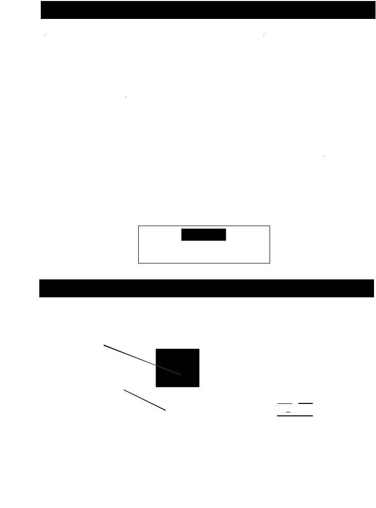
HOW TO FLUSH
FIGURE
Prime/Pressure Relief Valve (Prime/PR Valve) Used to relieve pressure from gun, hose & tip and to prime the unit when in OPEN position.
(It is in open position when there is a wider between valve handle cam body)
When valve is in the CLOSED position, there is only a very slight gap between handle & When closed the system is pressurized
FIGURE 2
PRESSURE CONTROL KNOB. (FIG. 2)
Used to adjust pressure. Turn clockwise (CW) to increase pressure and counterclockwise (CCW) to decrease pres-
FIGURE 3
ON 
 OFF
OFF
TOGGLE
SWITCH
Handle as a Loaded Firearm!
Continued on next page...........
5
HOW TO FLUSH (continued)
1. Be sure the gun safety latch is engaged and there is no spray tip in the gun. Refer to page 14 on how to lock the safety latch and the gun's safety features
FIGURE 4
REMOVE SPRAY TIP
ENGAGE GUN SAFE 
LATCH
2Pour enough clean, compatible solvent into a large, empty metal pail to fi ll the pump and hoses
3.Place the suction tube into the pail
4.Turn the Prime/Pressure Relief (PR) Valve to the "OPEN" , priming position. Refer to Figure 1
5.Point the gun into the metal pail and hold a metal
part of the gun fi rmly against the pail. Refer to Figure 5
To reduce the risk of static sparking which can cause fi re or explosion, always hold a metal part of the gun fi rmly against the metal pail when fl ushing. This also reduces splashing.
FIGURE 5
MAINTAIN FIRM
METAL TO METAL
CONTACT BETWEEN
GUN AND CONTAINER
6.Disengage the gun safety latch and squeeze the gun trigger. Turn the ON-OFF Toggle Switch to the "ON" position (Figure 3) and turn Pressure Control Knob (Figure 2) clockwise to increase pressure just enough to start the pump
7.Turn the Prime/PR Valve to the PRESSURE "CLOSED" position. This will allow solvent to be fl ushed through the pump, hoses and gun. Allow the
unit to operate until clean solvent comes from the gun
8.Release the trigger and engage the gun safety latch
9.Whenever you shut off the sprayer, follow the
"PRESSURE RELIEF PROCEDURE"
6
SETTING UP
1. Connect the hose and gun.
Remove the plastic cap plug from the outlet tee and screw a conductive or grounded 3000 psi airless spray hose onto fl uid outlet
b.Connect an airless spray gun to the other end of the hose
Do not use steel braided airless hose. Use nylon braided airless hose only
NOTE: Do not use thread sealer on swivel unions as they are made to self-seal.
Use thread seal on tapered male threads only.
2. Fill the packing nut/wet cup with
5 drops of Airlessco Throat Seal Oil (TSO). See (Figure 6)
FIGURE 6
3. Check the electrical service.
Be sure the electrical service is 120 VAC, 15 amp minimum, and that the outlet you use is properly grounded
NOTE: *For Generator power, a minimum 7000 watt generator with voltage regulation must be used.
4. Grounding
To reduce the risk of static sparking, fi re or explosion which can result in serious bodily injury and property damage, always ground the sprayer and system components and the object being sprayed, as instructed in the
safety warning section of this manual.
5. Flush the sprayer
As per "Flushing Procedure" in this manual
7
STARTING UP
1. Learn the functions of the controls.
PRIME/PRESSURE (PR) RELIEF VALVE is used to prime pump and to relieve pressure from gun, hose and tip
2. Prepare the material
Prepare the material according to the material manufacturer's recommendations
b.Place the suction tube into the material container
FIGURE 7
Prime/Pressure Relief Valve (Prime/PR Valve)
Used to relieve pressure from gun, hose & tip and to prime the unit when in the OPEN position. (It is in open position when there is a wider gap
between valve handle and cam body)
When in the CLOSED position, there is only a slight gapbetween handle When closed the system is
pressurized. Handle as a loaded fi rearm
3. Starting the sprayer (See Figure 7, 8 & 9)
Prime/PR Valve must be "OPEN" in the priming position
b.When you have ensured that the gun safety latch is engaged, attach tip and safety guard
Turn the ON-OFF Toggle Switch to the "ON" position
d.Turn Pressure Control Knob clockwise to prime the pump
After the pump is primed, turn Prime/PR Valve to the "Closed" position
f.Turn Pressure Control Knob to the desired spray pressure. Optional LCD displays pressure
Disengage the gun safety latch and you are ready to spray
FIGURE 8
ON
 OFF
OFF
TOGGLE
SWITCH
FIGURE 9
PRESSURE CONTROL KNOB is used to adjust pressure. Turn clockwise (CW) to increase pressure and counterclockwise (CCW) to decrease pressure
8
 Loading...