

Page 1
Operation/Repair/Parts
3A1186F
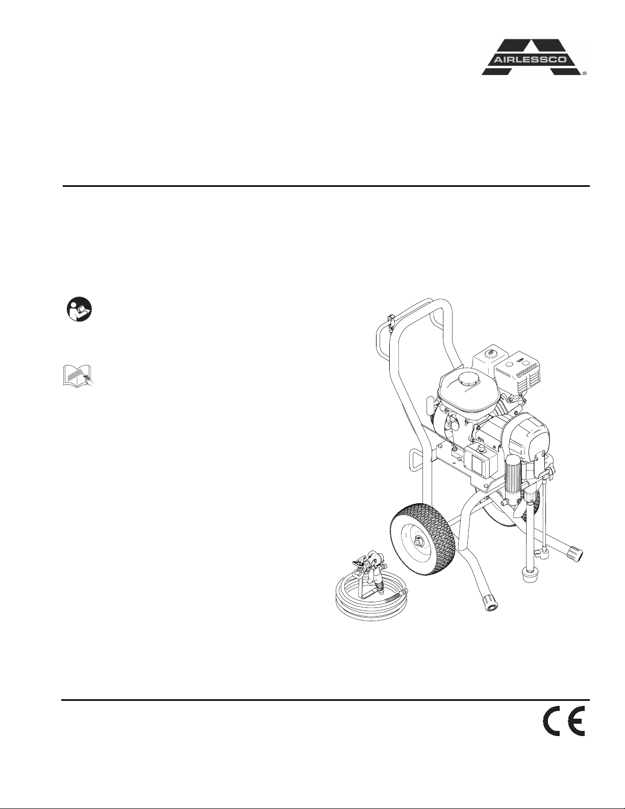
Airless Paint Sprayer
For application of architectural paints and coatings. For professional use only.
Airlessco - GS800 24F574, 16M531
3000 psi (20.7 MPa, 207 bar) Maximum Working Pressure
Important Safety Instructions
Read all warnings and instructions in this
manual. Save these instructions.
Related Manuals
Gun Manual
289316:
312363 - English
312364 - Spanish
312365 - French
24H289:
3A0479 - English
3A0480 - French
3A0481 - Spanish
EN
ti16161a
Page 2
Warnings
Warnings
The following warnings are for the setup, use, grounding, maintenance, and repair of this equipment. The exclamation point symbol alerts you to a general warning and the hazard symbols refer to procedure-specific risks. When
these symbols appear in the body of this manual, refer back to these Warnings. Product-specific hazard symbols and
warnings not covered in this section may appear throughout the body of this manual where applicable.
WARNING
WARNINGWARNINGWARNING
FIRE AND EXPLOSION HAZARD
Flammable fumes, such as solvent and paint fumes, in work area can ignite or explode. To help prevent
fire and explosion:
• Use equipment only in well ventilated area.
• Do not fill fuel tank while engine is running or hot; shut off engine and let it cool. Fuel is flammable and
can ignite or explode if spilled on hot surface.
• Eliminate all ignition sources; such as pilot lights, cigarettes, portable electric lamps, and plastic drop
cloths (potential static arc).
• Keep work area free of debris, including solvent, rags and gasoline.
• Do not plug or unplug power cords, or turn power or light switches on or off when flammable fumes are
present.
• Ground all equipment in the work area. See Grounding instructions.
• Use only grounded hoses.
• Hold gun firmly to side of grounded pail when triggering into pail.
• If there is static sparking or you feel a shock, stop operation immediately. Do not use equipment
until you identify and correct the problem.
• Keep a working fire extinguisher in the work area.
SKIN INJECTION HAZARD
High-pressure spray is able to inject toxins into the body and cause serious bodily injury. In the event that
injection occurs, get immediate surgical treatment.
• Do not aim the gun at, or spray any person or animal.
• Keep hands and other body parts away from the discharge. For example, do not try to stop leaks with
any part of the body.
• Always use the nozzle tip guard. Do not spray without nozzle tip guard in place.
• Use Airlessco nozzle tips.
• Use caution when cleaning and changing nozzle tips. In the case where the nozzle tip clogs while
spraying, follow the Pressure Relief Procedure for turning off the unit and relieving the pressure
before removing the nozzle tip to clean.
• Do not leave the unit energized or under pressure while unattended. When the unit is not in use, turn
off the unit and follow the Pressure Relief Procedure for turning off the unit.
• Check hoses and parts for signs of damage. Replace any damaged hoses or parts.
• This system is capable of producing 3000 psi. Use Airlessco replacement parts or accessories that are
rated a minimum of 3000 psi.
• Always engage the trigger lock when not spraying. Verify the trigger lock is functioning properly.
• Verify that all connections are secure before operating the unit.
• Know how to stop the unit and bleed pressure quickly. Be thoroughly familiar with the controls.
2 3A1186F
Page 3
Warnings
WARNING
WARNINGWARNINGWARNING
EQUIPMENT MISUSE HAZARD
Misuse can cause death or serious injury.
• Always wear appropriate gloves, eye protection, and a respirator or mask when painting.
• Do not operate or spray near children. Keep children away from equipment at all times.
• Do not overreach or stand on an unstable support. Keep effective footing and balance at all times.
• Stay alert and watch what you are doing.
• Do not leave the unit energized or under pressure while unattended. When the unit is not in use, turn
off the unit and follow the Pressure Relief Procedure for turning off the unit.
• Do not operate the unit when fatigued or under the influence of drugs or alcohol.
• Do not kink or over-bend the hose.
• Do not expose the hose to temperatures or to pressures in excess of those specified by Airlessco.
• Do not use the hose as a strength member to pull or lift the equipment.
PRESSURIZED ALUMINUM PARTS HAZARD
Use of fluids that are incompatible with aluminum in pressurized equipment can cause serious chemical
reaction and equipment rupture. Failure to follow this warning can result in death, serious injury, or
property damage.
• Do not use 1,1,1-trichloroethane, methylene chloride, other halogenated hydrocarbon solvents or
fluids containing such solvents.
• Many other fluids may contain chemicals that can react with aluminum. Contact your material supplier
for compatibility.
MOVING PARTS HAZARD
Moving parts can pinch, cut or amputate fingers and other body parts.
• Keep clear of moving parts.
• Do not operate equipment with protective guards or covers removed.
• Pressurized equipment can start without warning. Before checking, moving, or servicing equipment,
follow the Pressure Relief Procedure and disconnect all power sources.
CARBON MONOXIDE HAZARD
Exhaust contains poisonous carbon monoxide, which is colorless and odorless. Breathing carbon
monoxide can cause death.
• Do not operate in an enclosed area.
TOXIC FLUID OR FUMES HAZARD
Toxic fluids or fumes can cause serious injury or death if splashed in the eyes or on skin, inhaled, or
swallowed.
• Read MSDSs to know the specific hazards of the fluids you are using.
• Store hazardous fluid in approved containers, and dispose of it according to applicable guidelines.
BURN HAZARD
Equipment surfaces and fluid that’s heated can become very hot during operation. To avoid severe burns:
• Do not touch hot fluid or equipment.
3A1186F 3
Page 4

Warnings
WARNING
WARNINGWARNINGWARNING
PERSONAL PROTECTIVE EQUIPMENT
You must wear appropriate protective equipment when operating, servicing, or when in the operating area
of the equipment to help protect you from serious injury, including eye injury, hearing loss, inhalation of
toxic fumes, and burns. This equipment includes but is not limited to:
• Protective eyewear, and hearing protection.
• Respirators, protective clothing, and gloves as recommended by the fluid and solvent manufacturer.
CALIFORNIA PROPOSITION 65
The engine exhaust from this product contains a chemical known to the State of California to cause
cancer, birth defects or other reproductive harm.
4 3A1186F
Page 5
Component Identification
PRIME
ti14792a
PRESSURE
ti14791a
Component Identification
ti14790a
A
B
C
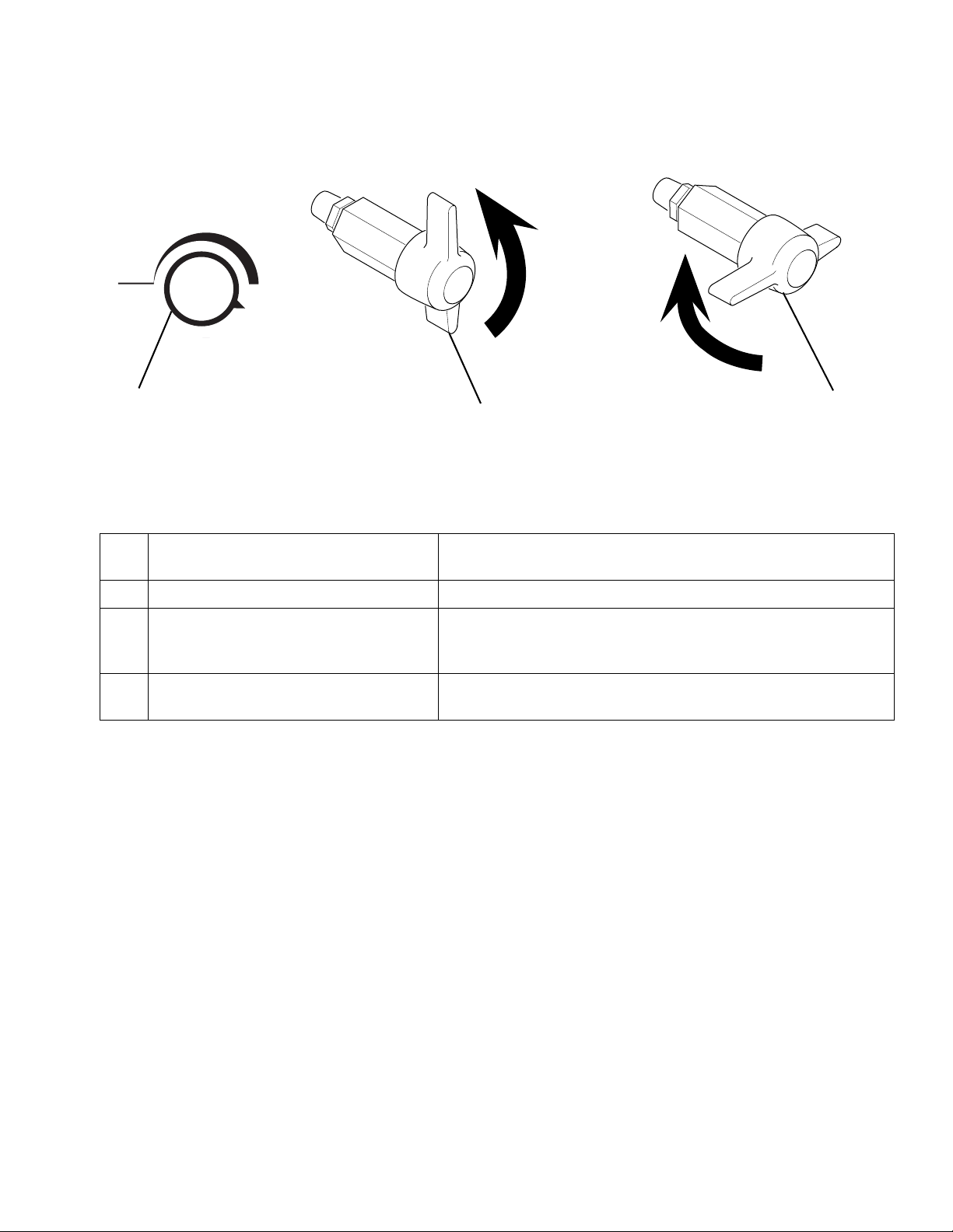
NOTE: The valve handle can move both clockwise and counter clockwise and can face different directions.
A Pressure Control Knob Adjusts pressure. Turn clockwise to increase pressure and
counterclockwise to decrease pressure.
Prime/Pressure (PR) Relief Valve Primes pump and relieves pressure from gun, hose and tip.
B Prime/Pressure (PR) Relief Valve Open
Position
Relieves pressure from gun, hose and tip and primes the unit
when in the open position. It is in the Open position when there
is a wider gap between valve handle and cam body.
C Prime/Pressure (PR) Relief Valve
Closed Position
Pressurizes system when closed. It is in the Closed position
when there is only a slight gap between handle and body.
3A1186F 5
Page 6
Operation
Operation
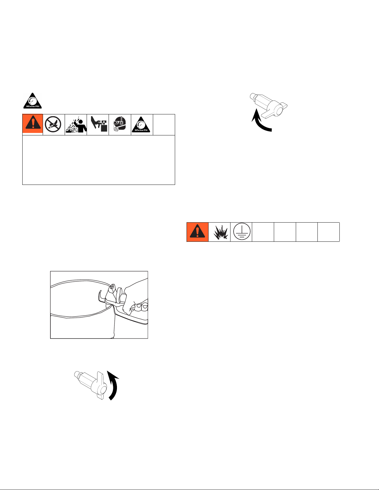
Pressure Relief Procedure
Follow the Pressure Relief Procedure whenever
you see this symbol.
This equipment stays pressurized until pressure is
manually relieved. To help prevent serious injury
from pressurized fluid, such as skin injection,
splashing fluid and moving parts, follow the Pressure
Relief Procedure when you stop spraying and before
cleaning, checking, or servicing the equipment.
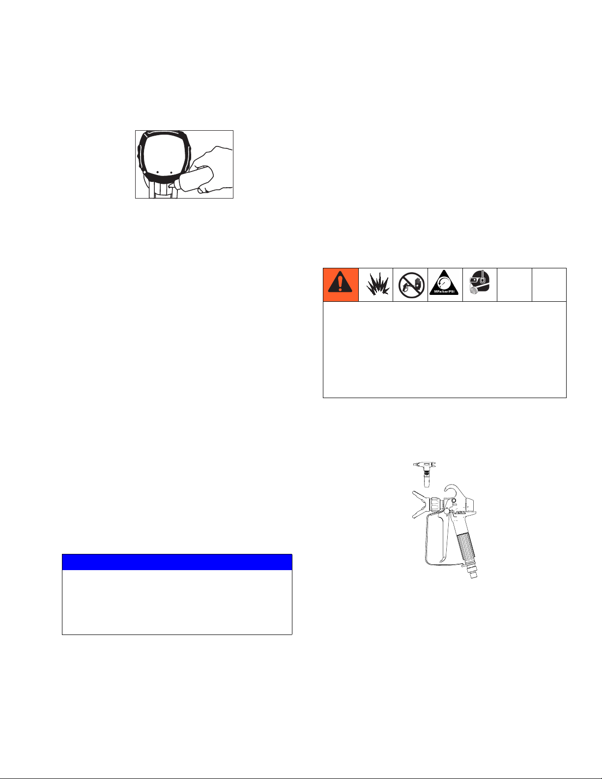
1. Engage the gun trigger lock. Refer to the separate
instruction manual provided with gun for safety features and how to engage the trigger lock.
2. Turn the unit off.
3. Disengage the gun trigger lock and trigger the gun
to relieve residual fluid pressure.
5. Re-engage gun trigger lock and close Prime/Pressure Relief Valve.
ti14790a
If the spray tip or hose is clogged, follow Steps 1
through 5 above. Expect paint to splash into the
bucket while relieving pressure during Step 4.
NOTE: If you suspect that pressure hasn’t been relieved
due to damaged Prime/Pressure Relief Valve, or other
reason, slowly loosen the tip nut or hose coupling.
Setup
Hold metal part of the gun in contact with
grounded metal pail. Use minimum pressure.
ti15989a
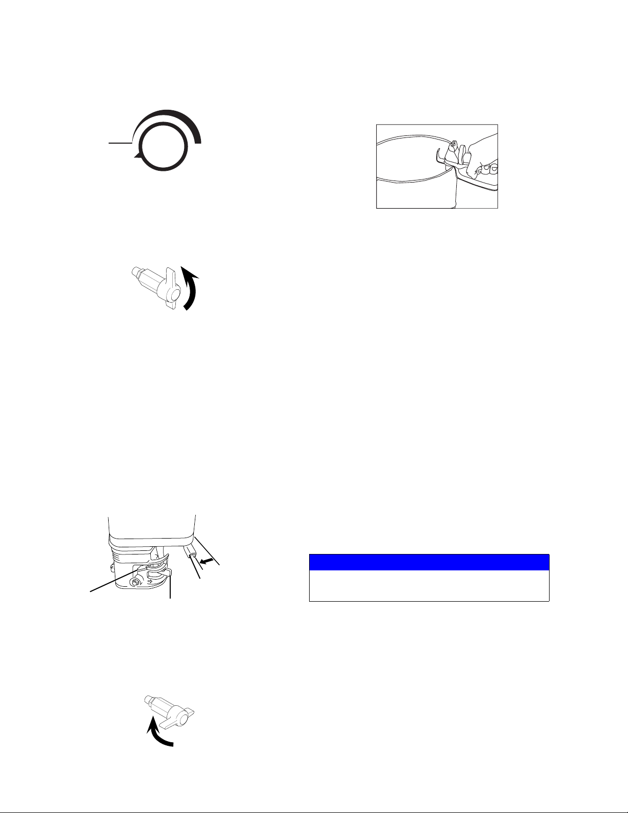
4. Turn Prime/Pressure Relief Valve (PR Valve) to the
open (priming) position to relieve residual pressure.
ti14791a
There will be a wider gap between valve handle
and cam body when in open position. In the
closed position there is only a very slight gap.
Grounding
Always ground the following components:
• Sprayer - Connect a ground wire and clamp (supplied) to a true earth ground.
• Fluid Hose - Use only grounded hoses.
• Spray Gun of Dispensing Valve - Grounding is
obtained through connection to a properly grounded
fluid hose and pump.
• Object being sprayed - According to local code.
Connect the hose and gun
1. Remove the plastic cap plug from the outlet and
screw a conductive or grounded 3000 psi spray
hose onto fluid outlet.
2. Connect an airless spray gun to the other end of the
hose. Do not install spray tip.
NOTE: Do not use thread sealer on swivel unions as
they are made to self seal.
NOTE: The valve handle can move both clockwise and
counter clockwise and can face different directions.
6 3A1186F
NOTE: The 6’ whip hose should always be 3/8”.
Page 7
Operation
Fill the Packing Nut/Wet Cup
1. Fill the Packing Nut/Wet Cup with 5 drops of Airlessco Throat Seal Oil (TSO).
ti16049a
Check the Engine Oil Level
1. Unscrew the oil fill plug. The dipstick is attached to
the plug.
2. Without threading the plug into place, check to be
sure the oil is up to the top mark of the dipstick.
3. If oil is needed, refer to engine manual.
Fill the Fuel Tank
1. Close the fuel shutoff valve.
2. Use only clean, fresh, well-known brands of
unleaded regular grade gasoline.
3. Remove the fuel cap and fill tank. Be sure the air
vent in the fill cap is not plugged so fuel can flow to
the carburetor, then replace the cap.
Oil- or Water-based Materials
• When changing from water-based material to oil
based material, flush with soapy water and then
mineral spirits.
• When changing from oil based material to water
base material, flush with mineral spirits, followed by
soapy water, then a clean water flush.
• When flushing with solvents, ground pail and gun.
• Flush before changing colors, before fluid can dry in
the equipment, at the end of the day, before storing,
and before repairing equipment.
Flushing
• To reduce the risk of static sparking, which can
cause fire or explosion, always hold a metal part of
the gun firmly against the metal pail when flushing.
This also reduces splashing.
• Always remove the spray tip before flushing.
• Only metal pails, which are conductive, should be
used as solvent pails when flushing.
1. Make sure the gun trigger lock in engaged and there
is no spray tip in the gun. Refer to the separate
instruction manual provided with gun for safety features and how to engage the trigger lock.
Flush the Sprayer
1. Flush the sprayer. See Flushing Procedure on
page 7.
Prime and Flush Storage Fluid
NOTICE
The equipment was tested with lightweight oil,
which is left in the fluid passages to protect parts.
To avoid contaminating your fluid with oil, flush the
equipment with a compatible solvent before using
the equipment for the first time.
Before beginning a new spraying project you need to
prime the sprayer and flush the storage fluid out of the
sprayer.
3A1186F 7
2. Pour enough clean, compatible solvent into a large,
empty metal pail to fill the pump and hoses.
3. Place the suction tube into the pail or place the pail
under the pump.
ti16028a
Page 8
Operation
4. Turn Pressure Control Knob counter clockwise to
lowest setting.
PRIME
HIGH PRESSURE
PRESSURE
ti21525a
5. Open the prime valve to the open - “Priming Position”. This will allow an easy start.
Open
(Priming and
Pressure Relief)
ti14791a
6. Turn the engine ON/OFF switch to ON.
7. Move the choke toward the closed position.
8. Move the throttle lever slightly to the left.
9. Turn the fuel valve ON. Pull the start rope. Pull the
engine over against compression stroke and then
let the rope rewind slowly into the starter. Pull firmly
and rapidly to start the engine. Do NOT drop the
rope. Hold on to the handle while rewinding, or the
rope may rewind improperly and jam the assembly.
If the engine does not start, open the choke all the
way and continue cranking.
11. Point the gun into the metal pail and hold a metal
part of the gun firmly against the pail. Maintain firm
metal to metal contact between gun and container.
ti15989a
12. Disengage the gun trigger lock and squeeze the
trigger. At the same time, slowly turn the pressure
control knob clockwise, just enough to move liquid
at low pressure. Close the prime spray valve.
13. Allow the pump to operate until clean solvent comes
from the gun.
14. Release the trigger and engage the gun trigger lock.
15. If you are going to start spraying, place the pump or
suction tube into the supply container. Release the
gun trigger lock and trigger the gun into another
empty, metal container, holding a metal part of the
gun firmly against the metal pail, forcing the solvent
from the pump and hose. When paint starts coming
from gun, turn pressure control knob to minimum
pressure, place prime valve in prime (open) position
and engage the gun trigger lock.
16. If you are going to store the sprayer, remove the
suction tube or pump from the solvent pail, force the
solvent from the pump and hose. Engage the gun
trigger lock. See Storage, 9.
17. Whenever shutting down the sprayer, follow Pres-
sure Relief Procedure, page 6.
NOTICE
Throttle Lever
Choke Lever
Fuel Valve
ti14793a
10. After the engine is warm, gradually close the choke,
raise the RPM of engine slightly by moving throttle
to the left. .
Closed
(Pressure)
To prevent damage and freezing during storage,
never leave water in the fluid pump
Startup
1. Prepare the material according to the material manufacturer’s recommendations.
2. Place the suction tube into the material container.
3. Start the sprayer.
a. Prime/PR Valve must be “OPEN” in the prim-
ti14790a
8 3A1186F
ing position.
Page 9
Operation
b. After ensuring the gun trigger lock is engaged,
attach tip and safety guard.
c. Turn the engine ON/OFF switch to the “ON”
position.Pull rope vigorously until engine
starts.
d. Turn the Pressure Control Knob clockwise to
prime the pump.
e. After the pump is primed, turn the Prime/PR
Valve to the “CLOSED” position.
f. Turn Pressure Control Knob to the desired
spray pressure.
g. Disengage the gun trigger lock to begin spray-
ing.
Adjusting the Pressure
• To reduce the risk of injection, never hold your
hand, body, fingers or hand in a rag in front of the
spray tip when cleaning or checking for a cleared
tip. Always point the gun toward the ground or into
a waste container when checking to see if the tip is
cleared or when using a self cleaning tip.
• When you spray into the paint bucket, always use
the lowest spray pressure and maintain firm metal
to metal contact between the gun and container.
• To stop the unit in an emergency, turn the engine
off. Then relieve the fluid pressure in the pump and
hose. See Pressure Relief Procedure, page 6
When adjusting the pressure, turn the Pressure Control
Knob clockwise to increase pressure and counterclockwise to decrease pressure. Always use the lowest pressure necessary to completely atomize the material. If
more coverage is needed, use a larger tip rather than
increasing the pressure. Check the spray pattern. The
tip size and angle determines the pattern width and flow
rate.
Shutdown
1. Relieve Pressure, page 6.
2. Clean the tip and gun as recommended in the separate Gun Manual supplied with the gun.
3. If spraying water-based material or a material that
could harden in the sprayer overnight, flush the
sprayer after use. See Flushing, page 7.
Storage
Short Term
1. Flush sprayer with compatible solvent before storing, then fill the pump and hoses with an oil based
solvent such as mineral spirits or Graco or Airlessco
Pump Armor.
• For oil base paint: flush with mineral spirits
• For water-base paint: flush with water, then min-
eral spirits and leave the pump, hose and gun
filled with mineral spirits.
Long Term
For longer storage, use Graco or Airlessco Pump
Armor. Shut off sprayer, Relieve Pressure, page 6, and
make sure prime valve is left open.
Start Up After Storage
Before using water-base paint, flush sprayer with soapy
water and then a clean water flush. When using oil-base
paint, flush out the mineral spirits with the material to be
sprayed.
NOTE: Always store unit indoors.
NOTICE
NOTE: Operating the sprayer at higher pressure
than needed wastes material, causes early tip wear,
and shortens sprayer life.
3A1186F 9
Page 10

Maintenance
Maintenance
Daily Maintenance
Keep displacement pump packing nut/wet cup lubricated with Airlessco Throat Seal Oil at all times. The
TSO helps protect the packings and rod. Inspect the
packing nut daily. If seepage of paint into the packing
nut and/or movement of the piston upward is found
(while not spraying), the packing nut should be tightened just enough to stop leakage. Overtightening will
damage the packings and reduce the packing life.
14
13
Servicing the Fluid Pump
Fluid Pump Disconnect
1. Relieve Pressure, page 6.
2. Flush the material you are spraying out of the
machine.
3. Remove the connecting rod shield (12).
4. Move the piston rod (10) to its lowest position by
cycling pump slowly.
5. Turn off the motor.
6. Disconnect sensor by holding it in place with a 7/8”
wrench and unscrewing the swivel with a 11/16”
wrench.
7. Remove the retaining ring (3) from the connecting
rod (13) and slide the sleeve (2) down revealing the
connecting rod pin (1).
8. Remove the suction tube assembly from the fluid
pump (9) by unscrewing the suction nut (7) with the
packing adjustment tool. (189211)
12
10
11
2
9
1
3
4
5
7
8
ti16053c
9. Using a 1/2” wrench unscrew the two bolts (8) from
the cover assembly (14). The fluid pump (9) will be
hanging loosely at this point.
10. Remove the connecting rod pin (1) out of the connecting rod, allowing the removal of the fluid pump
(9) from the machine.
10 3A1186F
Page 11

Maintenance
Fluid Pump Reinstall
1. Loosen the packing nut and ensure that the piston
rod (10) is in its upper position in the fluid pump
body (9). Slip the sleeve (2) and the retaining ring
(3) over the piston rod (10).
2. Push the piston rod (10) up into the connecting rod
(13) and align the holes. Insert the connecting rod
(13) and align the holes. Insert the connecting rod
pin (1) through the connecting rod (13) and piston.
Slip the sleeve (2) up over the connecting rod pin (1)
and insert the retaining ring (3) into the groove on
the connecting rod.
3. Push the two bolts (8) through the tube spacers (11)
and screw them into the cover assembly (14). Using
a 1/2” wrench, tighten the two bolts (8) evenly (alternating between them) until you reach 20 ft-lbs.
4. Reassemble lower suction valve assembly by placing the suction seat, O-ring, suction ball and suction
ball guide in the suction nut (7) and screw onto fluid
pump body (9).
5. Reconnect sensor to the fluid pump body (9). Hold
sensor with a 7/8” wrench while tightening the
swivel with a 11/16” wrench.
6. Start the machine and operate slowly to check the
piston rod(10) for binding. Adjust the two bolts (8),
holding the fluid pump body (9) to the cover assembly (14), if necessary. This will eliminate any binding.
Servicing the Outlet Valve
1. Disconnect the Fluid Pump, page 10.
2. Place piston holder in a vise. Slide piston into the
holder and lock in place with a 3/8” dowel.
3. Use 1/4” allen wrench to unscrew the outlet seat
retainer from the piston.
4. Remove the outlet seat, O-ring and outlet ball.
5. Inspect outlet ball and seat for wear, replace as necessary. Ensure seat is right side up.
6. While piston is still locked in the holder, install parts
back into the piston in the following order:
•Ball
•Outlet Seat
• O-Ring
NOTE: Before reinstalling the outlet seat support, apply
two drops of Loctite No. 242 (blue) on threads and
torque to 20 ft-lbs.
NOTE: Airlessco LP pump tool kit (188397) is required
for this task. Kit includes: Tightening Bar (865008),
Packing Removal Tool (331465), Piston Holder
(331195), 3/8” dowel (331196).
1
2
7. Tighten packing nut clockwise until resistance is felt
against the Belleville Springs, go 3/4 of a turn more.
Put five drops of Airlessco Throat Seal Oil in the
packing nut.
8. Run the machine at full pressure for several minutes. Release the pressure by following the Pressure Relief Procedure and readjust the packing nut
per step 7 above.
9. Install the connecting rod shield (12) so that the
small hole is in the upper right hand corner.
3A1186F 11
3
1
4
5
6
7
ti16054a
Page 12

Maintenance
Servicing the Inlet Valve
1. Un-thread and remove suction nut from fluid pump
body.
2. Remove suction seat, O-ring, suction ball and suction retainer.
3. Clean all parts and inspect them for wear or damage, replacing parts as needed.
4. Clean inside of the fluid pump body.
5. Reassemble lower suction valve assembly by placing the suction seat, O-ring, suction ball and suction
ball guide in the suction nut and screw onto fluid
pump body.
8
9
10
11
12
13
ti16055a
12 3A1186F
Page 13

Packing Replacement Procedures
Maintenance
Disassembly of the Fluid Pump
1. Disconnect the Fluid Pump, page 10.
2. Unscrew and remove the packing nut.
3. Push the piston rod down through the packings and
out of the pump.
4. Now push the packing removal tool up through the
pump and remove from the top bringing the packings, spacer and springs along with it, leaving fluid
body empty.
NOTE: Make sure all old packings and glands have
been removed from fluid pump.
5. Clean inside of fluid body.
6. Disassemble all parts and clean for reassembly.
Discard any old packings.
7. Lubricate leather packing in lightweight oil for 10
minutes prior to reassembly.
Reassembly of the Fluid Pump
1. Place lower male gland (1) down on the flat side.
7. Take the spacer (15) and slide over the top of the
piston (14) (it doesn’t matter which direction it sits),
falling onto the lower packings.
8. Take three Belleville Springs (16) and slide over the
top of the piston (14) in the following order:
• First spring - curve facing down
• Second spring - curve facing down
• Third spring - curve facing down
9. Take the upper male gland (17) and place it
rounded side up.
10. Take three upper polyethylene packings (18) and
two leather packings (22) and assemble with
inverted side down, on to the male gland (17) in the
following order:
• Polyethylene (18)
• Leather (22)
• Polyethylene (18)
• Leather (22)
• Polyethylene (18)
11. Take upper female gland (19) and place on top of
assembled upper packings with the inverted side
down.
2. Take three of the lower polyethylene packings (2)
and two of the leather packings (23) and place onto
the male gland (1), with the inverted side down, in
the following order:
• Polyethylene (2)
• Leather (23)
• Polyethylene (2)
• Leather (23)
• Polyethylene (2)
3. Take the female adaptor (3), which is inverted on
both sides, and place it on top of your assembled
lower packings.
4. Follow step 2 with your packings inverted side up.
5. Take the second lower male gland (1) and place it
on top of your assembled packings with rounded
side down.
6. Take assembled glands and packings (13 pieces)
and slide onto the lower half of the piston (14).
12. Take assembled upper glands and packings (7
pieces) and slide on over the top of the piston (14),
making sure inverted sides are down.
13. Take the packing holder (20) and replace the white
O-ring (24) and the black O-ring (25) with new ones
from the packing kit.
14. Slide the packing holder(20) over the top of the
upper packings so they fit inside.
15. Lubricate inside of the fluid pump body (4) and the
outside of the packings with a light weight oil.
16. Slide assembly into fluid pump body (4).
NOTE: To keep packings secured in correct position,
hold the pump body upside down and push the completed assembly upwards into the pump body. Once
placed inside, tilt pump body back up to keep all pieces
in.
17. Tighten the packing nut (21) into the top of the fluid
pump body (4) and tighten until you feel slight resistance against the Belleville Springs (16). Using the
3A1186F 13
Page 14

Maintenance
Packing Adjustment Tool, tighten another 3/4 of a
turn.
18. Reinstall Fluid Pump, page 11.
26
21
20
25
24
19
181818
17
161616
15
14
13
11
12
10
23232323
2222
1
222
3
1222
1
4
5
6
7
8
9
ti16056c
Replacement of Electrical Control Board
1. Remove electrical cover.
2. Disconnect sensor lead from Electrical Board.
3. Disconnect two clutch leads on Electrical Board
from leads on clutch.
4. Using a 1/16” allen, loosen set screw in Pressure
Control Knob and remove knob.
5. Using a 1/2” nutdriver or 1/2” deep socket, remove
nut from pressure control shaft. This will allow
removal of electrical control board from frame.
6. Replace Electrical Board Assembly in reverse order.
Adjust pressure. See Pressure Calibration of the
Electrical Control Board, page 14.
Pressure Calibration of the Electrical Control Board
1. Turn “Pressure Calibration” Trimpot adjustment on
electrical control board in the counter clockwise
direction at least 15 revolutions.
2. Connect 5000 psi glycerine pressure gauge on outlet of pump between fluid pump and airless hose to
monitor Fluid Pump Pressure.
3. Start engine and run at maximum RPM. Turn prime
Valve to open (Prime) position. Turn Pressure Control Knob to maximum position (fully clockwise).
4. Using an insulated screwdriver adjust “Pressure
Calibration” Trimpot by turning clockwise until the
clutch engages. When the clutch engages the pump
will commence Priming. When pump is primed, turn
the Prime Valve to the Closed (Pressure) Position.
NOTE: The pump will begin to pressurize and the clutch
will disengage at a low pressure. Continue turning the
trimpot clockwise to increase pressure 3000 psi.
5. Trigger gun. The pressure should drop approximately 350-400 psi, the clutch will engage and build
pressure to 3000 psi and disengage. Trigger gun
several times to ensure proper pressure setting.
6. Turn Pressure Control Knob to minimum position.
The clutch should disengage and pump stop moving.
14 3A1186F
Page 15

Maintenance
7. Secure leads with tie strap. 8. Replace cover on unit. Ensure the leads are not
pinched or damaged in the process of replacing
covers.
Engine - Single Wire Models
TO CLUTCH
CONTROL BOARD
TO ENGINE
Engine - Double Wire Models
BLACK
BLACK
BLUE
BLUE
BLUE
TO CONTROL BOX
TO CLUTCH
PRESSURE
CALIBRATION
ADJUSTMENT
SENSOR
BLACK
ti15392b
BLACK
BLUE
PRESSURE
CALIBRATION
ADJUSTMENT
CONTROL BOARD
BLUE
BLUE
SENSOR
BLACK
BLACK
ti14817b
TO ENGINE
3A1186F 15
Page 16

Troubleshooting
Troubleshooting
General
Problem Cause Solution
Unit doesn’t prime Airleak due to loose suction nut Tighten suction nut.
Airleak due to worn o-rings Replace o-ring (108526) on suction seat and
suction hose (331290), if so equipped.
Hole in suction hose Service outlet valve suction assembly.
Stuck or fouled balls
Unit primes but has poor or no
pressure
Unit does not maintain good
spraying pressure
Pressure set too low Turn up pressure.
Filter(s) are clogged Clean or replace gun filter, inlet filter, and/or
manifold filter.
Outlet valve fouled/worn. Service outlet valve.
Prime/pressure relief valve
bypassing
Packings and/or piston worn Tighten packing nut, repack unit.
Blown spray tip Replace spray tip.
Packings and/or pistons worn Repack unit.
Upper seat worn Replace upper seat.
Clean or replace prime valve.
16 3A1186F
Page 17

Troubleshooting
Electrical
Problem Cause Solution
Clutch does not engage Pressure Control Knob Ensure the pressure control knob is in the maxi-
mum clockwise position.
Poor Electrical Connection Remove the clutch and electrical box covers.
Check all electrical connections between the
engine magneto, sensor, control board and
clutch for loose connections or damaged leads.
Magneto Disconnect the two leads from the control board
(blue) and the clutch assembly (black). Using a
multimeter, with the engine at maximum RPM,
pressure control knob in the maximum position
and the prime valve open (priming) position, test
the DC voltage across the boards lead (blue).
This voltage must be 13-14 VDC. If the readings
are correct, the board, sensor and magneto are
functioning. See Clutch Assembly.
When the DC voltage from the board is not
13-14 VDC, disconnect the control board lead
(black) from the engine magneto lead (pink),
located on the side of the engine. With the
engine at maximum RPM (3600), pressure control knob in maximum clockwise position and
prime valve open (priming), read the AC voltage
from the magneto lead to the sprayer frame.
The reading should be 19-24 VAC. If outside
this range, replace the magneto. If the magneto
is producing proper voltage, see Defective Sen-
sor.
Defective Sensor Test the sensor by reading the resistance
between the red and black wires. The resistance
runs between 1.5 - 3K ohms. A defective sensor
usually shows no resistance (open). If the reading is outside standards, replace the sensor.
An alternative method of testing the sensor is to
plug a new sensor into the board to see if the
clutch will engage. When using this method,
ensure prime/pressure valve is in the prime
position because the sensor plugged into
the board in not measuring pressure in the
fluid section.
Clutch Assembly Check the spacing between the clutch field and
plate. The gap should be about .015”. If the gap
is greater than .015, replace the clutch assembly.
Electrical Control Board If the magneto and sensor are functioning,
replace the electrical control board.
3A1186F 17
Page 18

Troubleshooting
Airless Spray Gun
Problem Cause Solution
Coarse spray Low pressure Increase the pressure
Excessive fogging (overspray)
High pressure Reduce the pressure to satisfactory pattern dis-
tribution.
Material too thin Use less thinner
Pattern too wide Spray angle too large Use smaller spray angle tip
Pattern too narrow Spray angle too small Use larger spray angle tip (if coverage is OK, try
tip in same tip group)
Too much material Tip too large Use smaller tip
Material too thin
Pressure too high Reduce pressure
Too little material Tip too small Use next larger tip
Material too thick
Thin distribution in center of
pattern “horns”
Worn tip Change to new tip
Wrong tip Use nozzle with narrow spray angle
Thick skin on work Material too viscous Thin cautiously
Application too heavy Reduce pressure and/or use tip in next smaller
tip size
Coating fails to close and
Material too viscous Thin cautiously
smooth over
Spray pattern irregular,
deflected
Craters or pock marks, bubbles on work
Orifice clogged Clean carefully
Tip damaged Replace with new tip
Solvent balance Use 1 to 3% “short solvents remainder “long”
solvents (this is most likely to happen with material of low viscosity, lacquers, etc.)
Clogged screens Extraneous material in paint Clean screen
Course pigments Use coarse screen if orifice size allows.
Poorly milled pigments (paint
pigments glocculate)
Use courser screen, larger orifice tips. Obtain
ball milled paint. If thinner had been added, test
to see if a cover screen. Incompatible drop
placed on top of paint mixes or flattens out on
the paint mixture and thinners on the surface. If
not, try different thinner in fresh batch of paint.
Test the Pattern
Spotty Pattern,
Good, Full
Increase Pressure
ti15991a
18 3A1186F
Page 19

Parts
Manifold Filter (866480)
5
Parts
1
Qty
Ref. Part Description
1 867145 COVER 1
2
3
4
2SPRING 1
3 867377 O-RING 1
4 867214 FILTER 60 MESH 1
5 867647 SUPPORT 1
6 867077 BASE 1
7 867420 PLUG 2
9 867309 NIPPLE 3/8”M x 1/4”M 1
10 557391 PLUG 1/4” 1
.
6
9
Inlet Valve
12
7107
10
8
9
11
ti16052a
Qty
Ref. Part Description
8 331011 FLUID PUMP BODY 1
9 331029 SUCTION BALL GUIDE 1
10 331030 SUCTION BALL 1
11 108526 O-RING 1
12 331292 SUCTION SEAT 1
13 331034 SUCTION NUT 1
.
13
ti16055a
3A1186F 19
Page 20

Parts
Packing Replacement
Qty
Ref. Part Description
1* 331014 MALE GLAND 2
2* 331016 PACKING POLYETHYLENE 6
3* 331308 FEMALE ADAPTOR 1
4 331011 FLUID PUMP BODY 1
5 331029 SUCTION BALL GUIDE 1
6* 331030 SUCTION BALL 1
7* 108526 O-RING 1
8 331292 SUCTION SEAT 1
9 331034 SUCTION NUT 1
10+ 331314 OUTLET SEAT RETAINER 1
11+ 331026 OUTLET SEAT 1
12+* 111457 O-RING 1
13+* 331027 OUTLET BALL 1
14+ 331708 PISTON 1
15* 331018 SPACER 1
16* 331025 WASHER, SPRING 3
17* 331022 MALE GLAND 1
18* 331023 PACKING POLYETHYLENE 3
19* 331021 FEMALE GLAND 1
20 331019 PACKING HOLDER 1
21 331037 PACKING NUT 1
22* 331307 PACKING LEATHER 2
23* 331306 PACKING LEATHER 4
24* 107313 WHITE O-RING 1
25* 108771 O-RING 1
26 867783 CAP 1
* 331210 PACKING KIT
+ 331093 PISTON ASSEMBLY
1
.
26
21
222
20
25
23232323
3
24
19
181818
2222
1222
1
17
161616
4
15
5
6
7
14
8
13
11
9
12
10
ti16056c
20 3A1186F
Page 21

Notes
Notes
3A1186F 21
Page 22

Notes
Motor and Drive
39
89
88
34
29
96
56
37
57
58
69
35
35
38
75
31
41
42
74
100
72
60
64
71
98
70
59
6
45
44
68
34
43
75
74
15
292529
52
63
26
65
55
79 9293
13
28
20a
14
20d
20e
66
20a
20c
12
20b
18
17
95
11
76
4
5
3
40
46
99
87
86
47
49
48
50
84
85
22 3A1186F
94
82
51
83
27
30
32
ti16162a
Page 23

Notes
Qty
Ref. Part Description
3 305343 BRACKET MOUNTING PLATE 1
4 100527 WASHER,PLAIN 4
5 110838 NUT,LOCK 4
6+ 110005 NUT, JAM, HEX 4
11+ 114530 ENGINE,GAS,5.5HP,HONDA 1
12+
866212 KEY,SQUARE,3/16 X 1.35 1
13+ 331496 SCREW,SET, 5/16-24 4
14+ 24E115 BRACKET,MOUNTING,(WELD-
MENT)
15+ 100214 WASHER,LOCK 4
17+
NUT,LOCKING,DISTORTED
THREAD
18+ 112917 WASHER,LOCK,SPRING 3
20+
ADAPTER, CLUTCH ASSY 1
20a SCREW,SET,3/8-24 X .38 2
20b ADAPTER, CLUTCH 1
20c BUSHING 1
20d SCREW,SET, SOCKET HEAD 1
20e
BUSHING,PTFE LINED 1
25+
CLUTCH,ELECTROMAGNETIC 1
26+
SCREW,PAN HEAD,PHILLIPS 3
27+ 331294 SENSOR,SENSOR ASSY 1
28+ 867496 SCREW,1/4-20 X1.125 HX HD 2
29+*
867474 RING,RETAINING,EXTER-
NAL,15MM
30+ 867238 SWIVEL,FTG- SWIVEL, 1/4 X 1/4 1
31+
867290 KEY,5MM X 25MM 1
32+ 162453 FITTING,(1/4 NPSM X 1/4 NPT) 1
34* 866338 SCREW,SHOUL-
DER,SOCKET,MODIFIED
35* 107445 SCREW,CAP, SCH 2
37 331537 COVER-MACHINED STRIPER 1
38 331046 BALL BEARING 6204 1
39 867056 BEARING,BALL 1
40 331061 SLEEVE BEARING 1
41 331103 WASHER .562 .250 .060 .ST 2
42 331197 SCREW,10-24 X .50 .FLHD 2
43* 331038 YOKE,CROSSHEAD ASSY 1
44* 331062 SPRING,RET. SPRING 1
45* 331117 SLEEVE, 1
46* 331074 SPACER 2.691 LONG 2
47* 866482 PUMP,PAINT,ASSY, 5/8 STROKE 1
48 108526 PACKING,O-RING, PTFE 1
49 331029 RETAINER,PUMP 1
50 331030 BALL,BALL .500 GR100 ...SS 440 1
51* 867539 SCREW,5/16-18 X3.75 HX HD 2
52* 331590 GEAR - CRANK .32 ASSY 1
55* 331047 BEARING,BALL 1
56* 305340 SHAFT,PINION 1
57* 867079 BEARING,BALL 1
58* 305287 HOUSING,END BELL MACHINED 1
59* 867467 RETAINER,RING INTERNAL
40MM
60+ NUT 1/4-20 JAM NY-LOCK ST 2
63+ 100333 SCREW,CAP,HEX HD 4
Ref. Part Description
.
64+ 331178 TRIM,EDGE 1
65+ 103473 STRAP,TIE,WIRE 1
66+
867306 BASE,MOUNTING,WIRE,HAR-
NESS
68 305277 ENCLOSURE,CONTROL BOARD,
MACHINED
69 301282 CONTROL,PRESS. CONTROL 1
1
70 342520 LABEL PRESSURE 1
71 331184 SPACER 3/8 ID .54 OD .23L 1
72 867291 KNOB 1
74+ 100718 WASHER 2
3
75+ 331342 SCREW,10-24 X.50 PH PN HD 2
76 110837 SCREW,FLANGE,HEX 4
79 305268 COVER,ENGINE MOUNT 1
82 866428 VALVE,RELIEF/PRIMING 1
83 301348 HOSE,BYPASSS 12” LG. 1
84 866479 TUBE,SUCTION,SUBASSEMBLY 1
85 187190 STRAINER 1
86 331111 COVER,COVER - GUARD 1
87 866133 FITTING 3/8->1/4 NPT 1
88 331336 HOOK,PAIL 1
89 113783 SCREW,MACH,PNH 2
92
S 342473 LABEL GENERAL WARNING 1
93
2
S 342506 LABEL NEVER/ALWAYS LP&SL 1
94 342524 LABEL- PRIME VALVE 1
95 342461 LABEL, ENGINE SPEED 1
96 16F584 LABEL,AIRLESSCO, GS800,
FRONT
98 342522 LABEL, PRIME VALVE 1
2
99 866480 ASSY, FILTER 1
100 866082 PIN 1
101* 114819 GREASE (not shown) 1
+ 305341 MOTOR, & PUMP ASSY 1
* 305310 GEARBOX & PUMP ASSY 1
301666 CLUTCH HUB ASSY 1
1
Qty
.
1
1
1
3A1186F 23
Page 24

Notes
Frame Assembly (331447)
ti16164a
Qty
Ref. Part Description
1 331436 FRAME LP800G 1
2 111302 SCREW,CAP,HEX HD 4
4 100527 WASHER,PLAIN 4
5 110838 NUT,LOCK 4
6 331048 BOOT,RUBBER BOOT 2
7 143029 COLLAR,SCREW,SET (SPECIAL
ID)
8 867736 WHEEL-10’ OD X3.5’W 150LB 2
9 866356 SPACER .75 LG PVC 2
24 3A1186F
Ref. Part Description
.
10 866149 CLAMP,GROUNDING ASSY 1
14 24E115 BRACKET,MOUNTING,(WELD-
MENT)
36 124227 SCREW 2
97 HSE3850 HOSE 3/8” x 50’ (24F574) 1
2
865675 HOSE 3/8” X 50’ (16M531) 1
98 289316 GUN,500,2 FINGER,ASM,PACK-
AGED (24F574)
24H289 GUN, 009 (16M531)
Qty
.
1
1
Page 25

Suction Assemblies
Notes
Standard Suction Assy (331284)
2
3
4
5
Ref. Part Description
1 301348 BYPASS HOSE ASSY 1
2 331034 SUCTION NUT 1
3 331292 SUCTION SEAT ASSY 1
4 331400 INLET TUBE 1
5 187190 INLET STRAINER 1
1
ti16061a
Qty
Optional Suction Assy (331238)
1
8
2
.
4*
5*
3
6*
ti16062a
Qty
Ref. Part Description
1 331290 SUCTION HOSE ASSY 1
2 187651 INLET STRAINER 1
3 120777 PTFE O-RING 1
4* DRAIN HOSE 1
5* 241920 THREADED DEFLECTOR 1
6* 867759 MALE CONNECTOR 1
7 865721 INCLUDES (4, 5, 6, 8)
8 276888 DRAIN LINE CLIP
.
3A1186F 25
Page 26

Notes
Electrical System
Engine - Single Wire Models
TO CLUTCH
3
TO ENGINE
4
BLACK
BLACK
BLUE
3
BLUE
BLUE
BLACK
1
2
TO CONTROL BOX
PRESSURE
CALIBRATION
ADJUSTMENT
Engine - Double Wire Models
TO CLUTCH
BLACK
BLUE
SENSOR
5
ti15392b
PRESSURE
CALIBRATION
ADJUSTMENT
BLACK
SENSOR
5
ti14817b
Qty
Ref. Part Description
4
BLACK
3
TO ENGINE
Qty
. Ref. Part Description
BLUEBLUE
1
2
1 331184 SPACER 1 4 865676 CONTROL BOARD 1
2 867291 KNOB 1 5 866334 SENSOR
3 867352 O-RING 1
26 3A1186F
.
Page 27

Technical Data
Technical Data
Airless Paint Sprayer
US Metric
Maximum working pressure 3000 psi 20.7 MPa, 207 bar
Honda GX160 Engine
ANSI Power Rating @3600 RPM 5.5 Horsepower 4.1KW
Maximum delivery 0.80 gpm 3.6 lpm
Maximum tip size 0.029
Fluid outlet npsm 1/4 in.
Noise Level
Sound Power† 105 dBa
Sound Pressure** 96 dBa
Wetted parts zinc and nickel-plated carbon steel, nylon, stainless
steel, PTFE, acetal, leather, UHMWPE, aluminum, tung-
sten carbide
Notes
** Sound pressure measured at 3.1 feet (1m) from equipment.
† Sound power measured per ISO- 3744.
3A1186F 27
Page 28

Airlessco Standard Warranty
Airlessco warrants all equipment referenced in this document which is manufactured by Airlessco and bearing its name to be free from defects in
material and workmanship on the date of sale to the original purchaser for use. With the exception of any special, extended, or limited warranty
published by Airlessco, Airlessco will, for a period of twelve months from the date of sale, repair or replace any part of the equipment determined
by Airlessco to be defective. This warranty applies only when the equipment is installed, operated and maintained in accordance with Airlessco’s
written recommendations.
This warranty does not cover, and Airlessco shall not be liable for general wear and tear, or any malfunction, damage or wear caused by faulty
installation, misapplication, abrasion, corrosion, inadequate or improper maintenance, negligence, accident, tampering, or substitution of
non-Airlessco component parts. Nor shall Airlessco be liable for malfunction, damage or wear caused by the incompatibility of Airlessco
equipment with structures, accessories, equipment or materials not supplied by Airlessco, or the improper design, manufacture, installation,
operation or maintenance of structures, accessories, equipment or materials not supplied by Airlessco.
This warranty is conditioned upon the prepaid return of the equipment claimed to be defective to an authorized Airlessco distributor for verification
of the claimed defect. If the claimed defect is verified, Airlessco will repair or replace free of charge any defective parts. The equipment will be
returned to the original purchaser transportation prepaid. If inspection of the equipment does not disclose any defect in material or workmanship,
repairs will be made at a reasonable charge, which charges may include the costs of parts, labor, and transportation.
THIS WARRANTY IS EXCLUSIVE, AND IS IN LIEU OF ANY OTHER WARRANTIES, EXPRESS OR IMPLIED, INCLUDING BUT NOT
LIMITED TO WARRANTY OF MERCHANTABILITY OR WARRANTY OF FITNESS FOR A PARTICULAR PURPOSE.
Airlessco’s sole obligation and buyer’s sole remedy for any breach of warranty shall be as set forth above. The buyer agrees that no other remedy
(including, but not limited to, incidental or consequential damages for lost profits, lost sales, injury to person or property, or any other incidental or
consequential loss) shall be available. Any action for breach of warranty must be brought within two (2) years of the date of sale.
AIRLESSCO MAKES NO WARRANTY, AND DISCLAIMS ALL IMPLIED WARRANTIES OF MERCHANTABILITY AND FITNESS FOR A
PARTICULAR PURPOSE, IN CONNECTION WITH ACCESSORIES, EQUIPMENT, MATERIALS OR COMPONENTS SOLD BUT NOT
MANUFACTURED BY Airlessco. These items sold, but not manufactured by Airlessco (such as electric motors, switches, hose, etc.), are subject
to the warranty, if any, of their manufacturer. Airlessco will provide purchaser with reasonable assistance in making any claim for breach of these
warranties.
In no event will Airlessco be liable for indirect, incidental, special or consequential damages resulting from Airlessco supplying equipment
hereunder, or the furnishing, performance, or use of any products or other goods sold hereto, whether due to a breach of contract, breach of
warranty, the negligence of Airlessco, or otherwise.
FOR AIRLESSCO CANADA CUSTOMERS
The Parties acknowledge that they have required that the present document, as well as all documents, notices and legal proceedings entered into,
given or instituted pursuant hereto or relating directly or indirectly hereto, be drawn up in English. Les parties reconnaissent avoir convenu que la
rédaction du présente document sera en Anglais, ainsi que tous documents, avis et procédures judiciaires exécutés, donnés ou intentés, à la suite
de ou en rapport, directement ou indirectement, avec les procédures concernées.
TO PLACE AN ORDER OR FOR SERVICE, contact your Airlessco distributor,
or call 1–800–223-8213 to identify the nearest distributor.
All written and visual data contained in this document reflects the latest product information available at the time of publication.
Airlessco reserves the right to make changes at any time without notice.
For patent information, see www.graco.com/patents
Original Instructions. This manual contains English. MM 3A1186
Airlessco, 3501 N. 4th Avenue, Sioux Falls, SD 57104
Copyright 2010, Graco Inc. All Graco manufacturing locations are registered to ISO 9001
www.airlessco.com
Revised January 2014
 Loading...