

Page 1
Operation/Repair/Parts
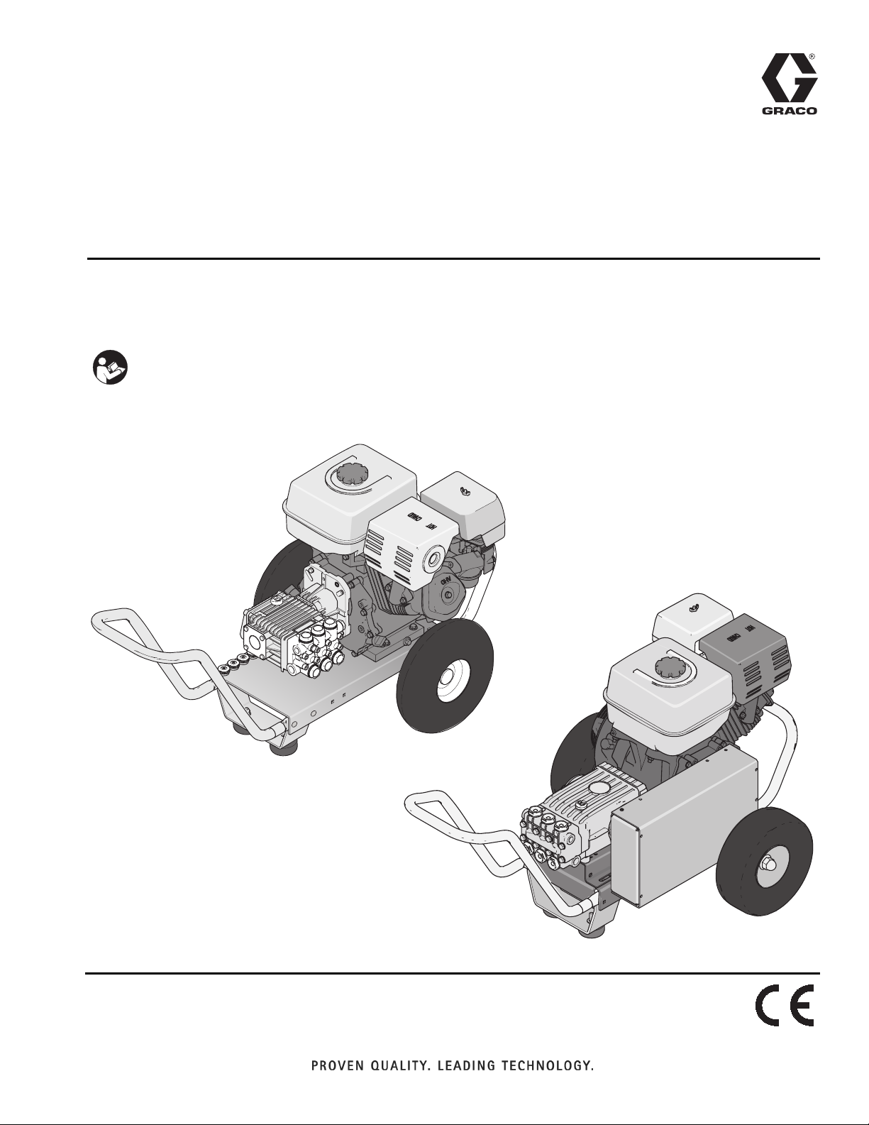
Pressure Washers
For high pressure water cleaning. For professional use only.
See page 2 for model information and maximum working pressure.
Important Safety Instructions
Read all warnings and instructions in this
manual and in the gas engine manual.
Save these instructions.
333031E
EN
ti22505a
Direct-Drive Models
ti22506a
Belt-Drive Models
Page 2

Models
Contents
Models . . . . . . . . . . . . . . . . . . . . . . . . . . . . . . . . . . . 2
Safety Symbols and Meanings . . . . . . . . . . . . . . 3
Warnings . . . . . . . . . . . . . . . . . . . . . . . . . . . . . . . . . 4
Installation . . . . . . . . . . . . . . . . . . . . . . . . . . . . . . . . 7
Personal Protective Equipment . . . . . . . . . . . . . . 7
Setup . . . . . . . . . . . . . . . . . . . . . . . . . . . . . . . . . . 7
Engine Fuel Tank . . . . . . . . . . . . . . . . . . . . . . . . 7
Pressure Relief Procedure . . . . . . . . . . . . . . . . . . . 8
Nozzle Review . . . . . . . . . . . . . . . . . . . . . . . . . . 9
Nozzle Connection . . . . . . . . . . . . . . . . . . . . . . 10
Water Supply . . . . . . . . . . . . . . . . . . . . . . . . . . 10
Unloader . . . . . . . . . . . . . . . . . . . . . . . . . . . . . . 11
Operation . . . . . . . . . . . . . . . . . . . . . . . . . . . . . . . . 12
Priming the Pump . . . . . . . . . . . . . . . . . . . . . . . 12
Start-Up . . . . . . . . . . . . . . . . . . . . . . . . . . . . . . . 13
Cleaning with Detergents . . . . . . . . . . . . . . . . . 14
Shutdown . . . . . . . . . . . . . . . . . . . . . . . . . . . . . 14
Maintenance . . . . . . . . . . . . . . . . . . . . . . . . . . . . . . 15
Engine . . . . . . . . . . . . . . . . . . . . . . . . . . . . . . . . 15
Pump . . . . . . . . . . . . . . . . . . . . . . . . . . . . . . . . . 15
Nozzles . . . . . . . . . . . . . . . . . . . . . . . . . . . . . . . 15
Quick Couplers . . . . . . . . . . . . . . . . . . . . . . . . . 15
Belt Tension Adjustment . . . . . . . . . . . . . . . . . . 15
Winterizing . . . . . . . . . . . . . . . . . . . . . . . . . . . . 16
Troubleshooting . . . . . . . . . . . . . . . . . . . . . . . . . . . 17
Parts (Belt-Drive Models) . . . . . . . . . . . . . . . . . . . 19
Sprayer Parts . . . . . . . . . . . . . . . . . . . . . . . . . . . 19
Sprayer Parts List . . . . . . . . . . . . . . . . . . . . . . . 20
Pump 127382 . . . . . . . . . . . . . . . . . . . . . . . . . . 21
Pump 127384 . . . . . . . . . . . . . . . . . . . . . . . . . . 22
Parts (Direct-Drive Models) . . . . . . . . . . . . . . . . . . 23
Sprayer Parts . . . . . . . . . . . . . . . . . . . . . . . . . . . 23
Sprayer Parts List . . . . . . . . . . . . . . . . . . . . . . . 24
Pump 127383 . . . . . . . . . . . . . . . . . . . . . . . . . . 25
Pump 127417 . . . . . . . . . . . . . . . . . . . . . . . . . . 26
Pump 127385 . . . . . . . . . . . . . . . . . . . . . . . . . . 27
Pump 127420 . . . . . . . . . . . . . . . . . . . . . . . . . . 28
Pump 127419 . . . . . . . . . . . . . . . . . . . . . . . . . . 29
Pump 127418 . . . . . . . . . . . . . . . . . . . . . . . . . . 30
Technical Data . . . . . . . . . . . . . . . . . . . . . . . . . . . . 31
Notes . . . . . . . . . . . . . . . . . . . . . . . . . . . . . . . . . . . . 35
Graco Standard Warranty . . . . . . . . . . . . . . . . . . . 36
Models
Part No. Model
24U618
24U626
24U619
24U985
24U620
24U986
24U987
24U621
24U988
24U622
24U989
24U623
24U990
24U624
24U991
24U625
2 333031E
2525DD 2500 17.2 172
2532DD 3200 22 220
3027DD 2700 18.6 186
3032DD 3200 22 220
4040DD 4000 27.6 276
4040DDC 4000 27.6 276
4040BD 4000 27.6 276
4040BDC 4000 27.6 276
Operating Pressure
PSI MPa Bar
Page 3
Models
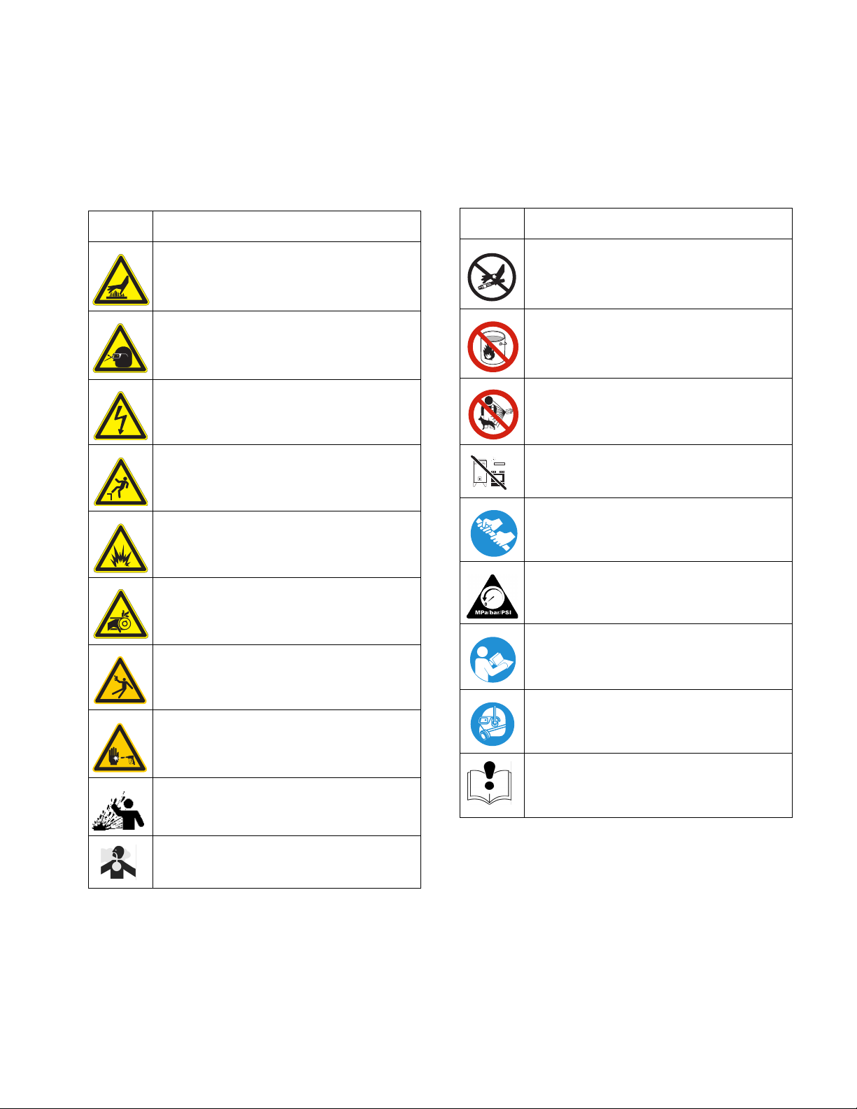
Safety Symbols and Meanings
The following safety symbols appear on the equipment and throughout this manual. It is important that you read the
table below and understand what each symbol means.
Symbol Meaning
Burn Hazard
Ejected Parts Hazard
Electric Shock Hazard
Fall Hazard
Fire and Explosion Hazard
Entanglement Hazard
Symbol Meaning
Do Not Stop Leaks or Deflect Leaks
Do Not Use Flammable Liquids
Do Not Spray People or Animals
Eliminate Ignition Sources
Hold Firmly With Both Hands
Perform Pressure Relief Procedure
Recoil Hazard
Skin Injection Hazard
Splash Hazard
Toxic Fluid or Carbon Monoxide Hazard
Read Manual Before Using Equipment
Wear Personal Protective Equipment
Equipment Misuse Hazard
333031E 3
Page 4
Warnings
Warnings
The following warnings are for the setup, use, grounding, maintenance, and repair of this equipment. The exclamation point symbol alerts you to a general warning and the hazard symbols refer to procedure-specific risks. When
these symbols appear in the body of this manual or on warning labels, refer back to these Warnings. Product-specific
hazard symbols and warnings not covered in this section may appear throughout the body of this manual where
applicable.
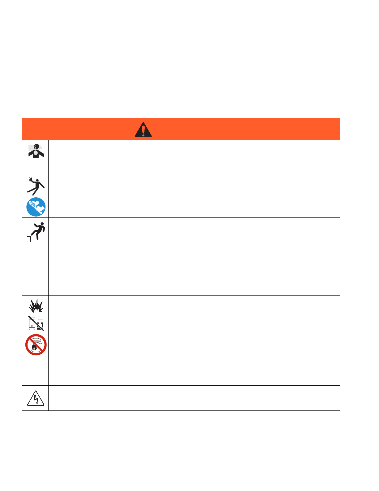
WARNING
WARNINGWARNINGWARNING
CARBON MONOXIDE HAZARD
Exhaust contains poisonous carbon monoxide, which is colorless and odorless. Breathing carbon
monoxide can cause death.
• Do not operate in an enclosed area.
RECOIL HAZARD
Gun may recoil when triggered. If you are not standing securely, you could fall and be seriously injured.
• Hold onto gun/wand firmly with both hands to avoid kickbacks.
FALL HAZARD
Use of this equipment can create puddles and slippery surfaces. High pressure spray could cause you to fall
if you are too close to the cleaning surface.
• Keep spray nozzle between 8 to 24 inches (20 to 60 cm) away from cleaning surface.
• Always operate equipment on a stable surface.
• Cleaning area should have adequate slopes and drainage to reduce possibility of falls due to slippery
surfaces.
• Be extremely careful if you must operate equipment from ladder, scaffolding, or any other relatively
unstable location.
FIRE AND EXPLOSION HAZARD
Flammable vapors in the work area and can ignite or explode. To help prevent fire and explosion:
• Do not spray flammable liquids.
• Operate pressure washers outdoors only.
• Eliminate all ignition sources; such as pilot lights, cigarettes, portable electric lamps, and plastic
drop cloths (potential static arc).
•
When transporting or repairing equipment, transport or repair with the fuel tank empty or with fuel shutoff
valve turned off.
• Do not fill fuel tank while engine is running or hot; shut off engine and let it cool. Fuel is flammable and
can ignite or explode if spilled on hot surface.
• Keep work area free of debris, including solvent, rags and gasoline.
ELECTRIC SHOCK HAZARD
Spray contact with electrical wiring can result in serious injury or death.
• Keep water spray away from electric wiring.
4 333031E
Page 5
Warnings
WARNING
WARNINGWARNINGWARNING
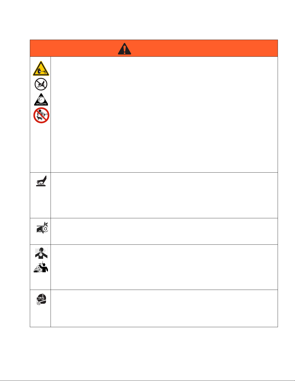
SKIN INJECTION HAZARD
High-pressure spray is able to inject toxins into the body and cause serious bodily injury. In the event that
injection occurs, get immediate surgical treatment.
• Keep clear of nozzle. Do not spray any person, yourself or any animal.
• Keep hands and other body parts away from the discharge. Do not try to stop leaks with any part of the
body.
• This product is to be used only by trained operators.
• Use caution when cleaning and changing nozzle tips. In the case where the nozzle tip clogs while
spraying, follow the Pressure Relief Procedure for turning off the unit and relieving the pressure before
removing the nozzle tip to clean.
• Do not leave the unit energized or under pressure while unattended. When the unit is not in use, turn off
the unit and follow the Pressure Relief Procedure for turning off the unit.
• Check hoses and parts for signs of damage. Replace any damaged hoses or parts.
• Use Graco replacement parts or accessories that are approved for the rated pressure of the pressure
washer.
• Always engage the trigger lock when not spraying. Verify the trigger lock is functioning properly.
• Verify that all connections are secure before operating the unit.
• Know how to stop the unit and bleed pressure quickly. Be thoroughly familiar with the controls.
BURN HAZARD
Running engines produce heat and hot exhaust gases. Temperature of muffler and nearby areas can reach
or exceed 150° F (65° C). Fire or severe burns can occur.
• Do not touch hot surfaces.
• Stay clear of exhaust gases.
• Never move equipment while operating.
• Allow equipment to cool before touching.
ENTANGLEMENT HAZARD
Rotating parts can cause serious injury.
•
Keep clear of moving parts.
• Do not operate equipment with protective guards or covers removed.
TOXIC FLUID HAZARD
Toxic fluids or fumes can cause serious injury or death if splashed in the eyes or on skin, inhaled, or
swallowed.
• Do not use pressure washer to dispense hazardous detergents or acid-type cleaners.
• Do not alter chemical injector feature that is listed in the manual.
• Read MSDSs to know the specific hazards of the fluids you are using.
• Route exhaust away from work area.
PERSONAL PROTECTIVE EQUIPMENT
Wear appropriate protective equipment when in the work area to help prevent serious injury, including eye
injury, hearing loss, inhalation of toxic fumes, and burns. This protective equipment includes but is not
limited to:
• Protective eyewear, and hearing protection.
• Respirators, protective clothing, and gloves as recommended by the detergent manufacturer.
333031E 5
Page 6
Warnings
WARNING
WARNINGWARNINGWARNING
EQUIPMENT MISUSE HAZARD
Misuse can cause death or serious injury.
• Always wear appropriate gloves, eye protection, and a respirator or mask when spraying.
• Do not operate or spray near children. Keep children away from equipment at all times.
• Do not overreach or stand on an unstable support. Keep effective footing and balance at all times.
• Stay alert and watch what you are doing.
• Do not leave the unit energized or under pressure while unattended. When the unit is not in use, turn
off the unit and follow the Pressure Relief Procedure for turning off the unit.
• Do not operate the unit when fatigued or under the influence of drugs or alcohol.
• Keep operating area clear of all persons.
• Do not kink or over-bend the hose.
• Do not expose the hose to temperatures or to pressures in excess of those specified by manufacturer.
• Do not use the hose as a strength member to pull or lift the equipment.
• Follow the maintenance instructions specified in the manual.
• Do not alter or modify equipment. Alterations or modifications may void agency approvals and create
safety hazards.
• Make sure all equipment is rated and approved for the environment in which you are using it.
CALIFORNIA PROPOSITION 65
The engine exhaust from this product contains a chemical known to the State of California to cause
cancer, birth defects or other reproductive harm.
This product contains a chemical known to the State of California to cause cancer, birth defects or other
reproductive harm. Wash hands after handling.
The following instructions are required by California state law, section 4442 of the California Public
Resource Code. Other states may have similar laws. Federal laws apply on federal land.
• A spark arrestor must be added to the muffler of this engine if it is to be used on any forest-covered,
brush-covered, or grass-covered unimproved land.
• See your engine or equipment dealer for spark arrestor muffler options.
6 333031E
Page 7
Installation
Installation
Personal Protective Equipment
INJECTION AND INHALATION HAZARD
Proper attire is essential to your safety. It is advised
to utilize whatever means necessary to protect eyes,
ears and skin. Additional safety attire (such as
respiratory mask) may be required when using
detergent cleaning agents with this washer.
Setup
This unit should only be placed on a level surface while
operating to ensure proper lubrication for the engine and
water pump.
FIRE AND EXPLOSION HAZARD
Do not use unit in an area:
• with insufficient ventilation
• where there is evidence of oil or gas leaks
• where flammable gas vapors may be present
Be certain to block wheels to prevent unit from moving
while operating.
Once properly installed, check the oil sight glass on the
pump crankcase. Make sure the oil level is in the center
of the sight glass before each use. If the level appears
to be low, add pump oil and fill only to the center of the
oil sight glass. Refer to the Parts List for the correct
pump oil. Do not overfill!
Engine Fuel Tank
A minimum of 86 octane fuel is recommended for use
with this unit. Do not mix oil with gasoline.
Purchase fuel in quantities that may be used within 30
days. Use of clean, fresh lead-free gasoline is recommended. Leaded gasoline may be used if lead-free is
unavailable. Do not use gasoline containing methanol or
alcohol.
Check the engine oil level before starting the engine
(see engine manual).
Fill the fuel tank according to engine manual.
Occasional carburetor and choke adjustments will be
necessary for the engine. Refer to the engine manual
supplied with this unit for proper adjustment procedures.
Review the engine manual accompanying this pressure
washer for correct engine start-up and maintenance procedures.
BURST HAZARD
Do not allow unit to be exposed to rain, snow or freezing temperatures. If any part of the unit becomes frozen, excessive pressure may build up which could
cause it to burst and result in possible serious injury.
Before initial use, make sure the oil cap/dipstick is
inserted into the pump. Because of varying shipping
requirements, the pump may need to be shipped with an
oil travel plug instead of the dipstick in the pump. If your
pump has been shipped with an oil travel plug, you will
need to remove it and replace the plug with the oil dipstick provided with the unit.
333031E 7
Page 8
Pressure Relief Procedure
Pressure Relief Procedure
Follow the Pressure Relief Procedure whenever
you see this symbol.
This equipment stays pressurized until pressure is
manually relieved. To help prevent serious injury
from pressurized fluid, such as skin injection,
splashing fluid and moving parts, follow the Pressure
Relief Procedure when you stop spraying and before
cleaning, checking, or servicing the equipment.
1. Engage trigger lock.
2. Turn unit off.
3. Shut off water supply. Disconnect from water.
4. Disengage trigger lock.
5. Trigger gun to relieve pressure.
6. Engage trigger lock.
7. If you suspect the spray tip or hose is clogged or
that pressure has not been fully relieved after following the steps above, VERY SLOWLY loosen hose
end coupling to relieve pressure gradually, then
loosen completely. Clear hose or tip obstruction.
8 333031E
Page 9
Nozzle Review
Pressure Relief Procedure
Various nozzles may be quick-connected into the end of
the wand to change the spray pattern or use the detergent feature.
EJECTED PARTS HAZARD
When using Quick Connects, be certain the
connection is securely locked. If connections are not
securely locked, the high pressure water may eject
the nozzle from the wand, causing severe injury or
serious damage.
Always point wand always from you when changing
nozzle. Perform Pressure Relief Procedure
(page 8) before changing nozzle.
To determine spray fan, refer to the number stamped on
the nozzle. The first two digits indicate the spray fan
degrees, i.e.; 0=0°, 25=25°, 40=40°, 65 = detergent/low
pressure.
0° nozzle (RED): This is a blasting nozzle, which delivers a very concentrated stream of water. Be cautious
when using the straight narrow stream. It is not recommended for use on painted or wood surfaces, or items
attached with adhesive backings. Uses: Removing
weeds from sidewalk cracks, stubborn stains from concrete, masonry, aluminum and steal, caked mud from
equipment, and cleaning lawn mower undersides.
15° nozzle (YELLOW): This is a chiseling nozzle. The
spray should be directed at a 45° angle to the surface
and used like a scraper to remove paint, grease and dirt.
Uses: Surface preparation (removing mildew stains and
paint chips).
25° nozzle (GREEN): This is a flushing nozzle. This
pattern is best suited for flushing dirt, mud, and grime.
Uses: Wet sweeping leaves from walks, curbs and
driveways, cleaning stable floors, washing swimming
pool bottoms, and de-greasing engines.
40° nozzle (WHITE): This is a wash nozzle. This wide
spray pattern disperses the water pressure over a larger
area and is recommended for moderate washing. Uses:
Washing down aluminum siding, cleaning windows,
washing vehicles, spraying sidewalks, driveways and
patios. NOTE: Not available for Model 2525.
65° nozzle (BLACK): This is a low pressure detergent
application nozzle. This broad spray pattern distributes
solution over vast areas under low pressure. Uses:
Detergent application, misting or rinsing.
333031E 9
Page 10

Pressure Relief Procedure
Nozzle Connection
1. Perform Pressure Relief Procedure, page 8.
2. Engage trigger lock.
3. The nozzle assembly should be disconnected from
the gun/wand assembly at this time by retracting the
locking ring on the quick-connect fitting to remove
the nozzle.
Water Supply
Select a water supply hose which is a quality grade of
garden hose measure at least 3/4 in. (19.05 mm) ID and
no longer than 50 feet (15.24 m).
Check the water inlet strainer to make sure it is clean
and free of any obstructions. Periodic cleaning of the
water strainer will help prevent pump problems.
NOTICE
As a strainer becomes obstructed, it restricts proper
flow of water to the pump. This can result in cavitation
which will cause premature failure of pump packings.
1. Unscrew garden hose inlet connection from front of
filter assembly.
2. Remove clear plastic cover and clean filter screen.
Connect the hoses
1. Connect one end of water supply hose to water inlet
of unit.
2. Connect other end of hose to pressurized water
supply. When connecting water inlet to water supply
mains, local regulations of your water company
must be observed. In some areas, the unit must not
be connected directly to public drinking water supply. This prevents feedback of the detergents into
the water supply. Direct connection is permitted if a
back flow preventer is installed.
3. Quick-connect high pressure discharge hose to
water outlet of unit.
4. Connect other end of discharge hose to gun assembly.
Follow incoming water requirements listed below:
1. Water pressure must be a minimum of 25 psi (0.17
MPa,1.72 bar) and a maximum of 125 psi (0.86
MPa, 8.6 bar). NOTE: A typical outdoor faucet will
generally supply this psi if fully turned on.
2. Incoming GPM must be at least one gallon more
than the outgoing GPM stated on pressure washer
nameplate. NOTE: You can check GPM by timing
how long it takes to fill a 5 gallon container.
NOTICE
Incoming water temperature must not exceed 140° F
(60° C). Excessive pump damage may result if the
water temperature exceeds this acceptable level.
Never allow the unit to operate without the incoming
water line attached and the water supply fully turned
on. Damage to the equipment could occur.
10 333031E
Page 11
Unloader
Pressure Relief Procedure
Adjustment Knob
The unloader valve on your machine is equipped with an
adjustment knob to adjust the pressure. If less pressure
is needed, turn the adjustment knob counter-clockwise.
To set back to maximum, turn adjustment knob fully
clockwise. Do not over tighten.
NOTICE
Do not overtighten the unloader. Breakage could
result in immediate loss of water pressure and costly
repairs.
Thermal Relief Valve
To ensure the water temperature does not exceed
acceptable levels, never allow the unit to operate in the
bypass mode (unit running with gun trigger closed) for
more than three minutes.
A thermal relief valve has been added to this unit to protect the pump. It may begin to open and release water if
the water temperature in the pump has exceeded 140°F
(60°C). This will allow fresh, cool water to enter the system.
Pre-Start Inspection Procedures
Before starting the unit, perform the following procedures:
1. Check oil level in pump and engine.
2. Inspect water inlet strainer. Clean or replace if necessary (see Water Supply, page 10).
3. Check all hose connections to make sure they are
tightened securely (see Water Supply, page 10).
FIRE AND EXPLOSION HAZARD
Inspect for system fuel leaks. If a fuel leak is found,
do not start unit. See Fire and Explosion Hazard on
page 4. Make sure all damaged parts are replaced
and mechanical problems are corrected prior to
operation of unit. If service is required, contact Graco
Customer Service.
INJECTION HAZARD
Inspect high pressure hoses for kinking, cuts and
leaks. If a cut or leak is found, do not use hose.
Replace hose before starting unit (see Skin
Injection Hazard, page 5). Be sure that all damaged
parts are replaced and that the mechanical problems
are corrected prior to operation of the unit. If you
require service, contact Graco Customer Service.
333031E 11
Page 12

Operation
Operation
Priming the Pump
It is essential to prime the pump on initial start-up and
each time the water supply is disconnected from the unit
after initial use.
1. Lay high pressure hose out to remove any loops.
Water flow will constrict hose and create tight loops
if hose is not straight.
NOTE: The nozzle assembly should not be connected to the gun assembly at this time. See Nozzle
Connection, page 10.
2. Engage trigger lock and turn water supply fully on.
Point gun away from yourself or anyone else, disengage trigger lock and squeeze trigger.
NOTE: Low pressure water will begin flowing from
hose/gun assembly. This allows unit to prime and
purge any air from system. Unit is primed when
water flow is uninterrupted by air.
3. Once unit is primed, release trigger and engage trigger lock. Securely connect nozzle assembly (see
Nozzle Connection, page 10).
NOTICE
Make sure the nozzle is not connected to the unit
while priming the pump. Priming allows mineral
deposits to be released from the system which could
obstruct or damage the nozzle assembly resulting in
costly repairs.
12 333031E
Page 13

Start-Up
Operation
Never look directly into the nozzle. High pressure
water creates a risk for severe injury.
1. Engage trigger lock and point gun away from yourself or anyone else. Make sure water supply is fully
turned on.
2. Disengage trigger lock and squeeze trigger. Low
pressure water will begin flowing from nozzle.
3. Make sure gun remains in an open position while
starting engine. NOTE: Brace yourself. Gun will
kickback from high pressure created by pump once
engine has started.
4. Steady unit during engine start-up. See accompanying engine manual for correct procedures needed to
start engine.
5. Once engine has started, perform the following procedures with gun open:
FIRE AND EXPLOSION HAZARD
Inspect for system oil leaks and fuel leaks. If a fuel
leak is found, immediately turn off unit. Make sure all
damaged parts are replaced and mechanical
problems are corrected prior to operation of unit. If
service is required, contact Graco Customer Service.
INJECTION HAZARD
Inspect high pressure hoses for kinking, cuts and
leaks. If a cut or leak is found, do not touch hose at
leak. Turn unit off immediately. Replace hose before
restarting unit. Make sure all damaged parts are
replaced and mechanical problems are corrected
prior to operation of unit. If service is required,
contact Graco Customer Service.
6. Trigger gun several times. Make sure to engage
trigger lock whenever changing quick-connect nozzles.
NOTICE
Do not allow unit to operate in bypass mode (with trigger closed) for more than three minutes without triggering gun. This can cause premature failure of pump
packing seals and result in costly pump repair.
This pressure washer delivers a high pressure spray
and a variety of spray patterns. There are many cleaning jobs that can be done without the use of detergents.
If a cleaning agent is required, see Cleaning with
Detergents (page 14) for correct procedures.
NOTICE
Do not allow spray pattern to remain on a fixed area
for an extended period of time. Possible damage to
that area may occur.
333031E 13
Page 14

Operation
Cleaning with Detergents
BURN OR EXPLOSION HAZARD
Always wear protective safety attire.
4. To rinse; engage trigger lock and securely connect
desired high pressure nozzle into end of wand. Disengage trigger lock and spray. It will take about 30
seconds to purge all detergent from line. For best
rinsing results, start at the top and work down.
Prepare detergent solution according to label directions. Never pump
cleaners
Some units are equipped with adjustable detergent
knobs. Locate the clear vinyl hose which leads to the
pump head.
If injector is equipped with adjustment knob on pump
head, detergent amount can be adjusted by turning the
knob completely counter-clockwise to set at maximum
siphon rate.
If injector is not equipped with an adjustment knob,
detergent ratio is preset and cannot be adjusted.
1. Immerse detergent strainer into detergent solution
2. Engage trigger lock and secure quick-connect
NOTE: This injection system is designed to apply detergents under low pressure only. It will not allow detergent
solutions to be introduced into the system unless the
nozzle assembly is in the low pressure detergent mode.
through unit.
to allow detergent to siphon.
detergent spray nozzle (#6540° BLACK) into end of
wand.
hazardous detergents or acid-type
5. Siphon a gallon of water through low pressure
detergent injection system after each use. This
reduces the possibility of corrosion or detergent residue causing mechanical problems during next use.
Shutdown
1. Turn engine “OFF” (see engine manual).
2. Turn water supply “OFF”.
3. Point gun in a safe direction and trigger gun to
relieve any trapped pressure.
4. Once pressure is relieved, disconnect nozzle
assembly.
5. Disconnect and drain gun, wand and hose.
6. Wipe unit clean and store with gun, wand and hoses
in a non-freezing area.
3. To apply solution; disengage trigger lock and
squeeze trigger. A detergent/water mixture will exit
low pressure nozzle. Start spraying lower portion of
surface being cleaned and move up, using long
overlapping strokes. NOTE: Applying from the bottom up helps avoid streaking. Allow to soak briefly.
Do not allow detergent solution to dry on the surface. Avoid working on hot surfaces or in direct sunlight to minimize the chances of the detergent
drying, which may result in damaging painted surfaces. Rinse a small section at a time.
14 333031E
Page 15

Maintenance
Maintenance
Engine
The engine instructions that accompany the unit detail
specific procedures for engine maintenance. Following
the engine manufacturer's recommendations will extend
engine work life.
Pump
The pump oil must be changed after the first 25 hours of
operation on all units. Once the initial oil change has
been completed, it is recommended the oil be changed
every 3 months or 250 hour intervals. If oil appears dirty
or milky, changes may be required at a greater frequency. Add pump oil and fill only to the center of the
sight glass. Refer to the parts listing for the correct
pump oil. Do not overfill.
Nozzles
Water flow through the spray nozzle will erode the orifice, making it larger and result in a pressure loss. Nozzles should be replaced whenever pressure is less than
85% of the maximum. The frequency of replacement will
depend upon such variables as mineral content in the
water and number of hours the nozzle is used.
Quick Couplers
There is an o-ring seal inside the female quick coupler.
This o-ring will deteriorate or, if the unit is allowed to
pump without the high pressure hose or nozzle
attached, the o-ring may be blown out occasionally.
Insert a replacement o-ring to correct the leak. Additional o-rings can be purchased from your dealer.
Belt Tension Adjustment
To maintain peak performance, it may be necessary to
occasionally adjust the belt tension. Perform the following steps:
1. Remove belt guard and loosen two nuts on each
side of pump (A).
2. Turn cap screw (B) clockwise until a 1/2 in. (12.7
mm) belt deflection is noticed between the pulleys.
3. Tighten side nuts (A).
4. Put a straight edge across both pulleys. If necessary, loosen one set of pulley screws and adjust in
or out to properly align. Tighten pulley screws and
check tension again.
5. Replace belt guard and tighten fasteners securely.
333031E 15
Page 16

Maintenance
Winterizing
For storage and transportation purposes in subfreezing
ambient temperatures, it will be necessary to winterize
the unit. The unit must be protected to the lowest
incurred temperature for the following reasons:
• If any part of the pumping system becomes frozen;
excessive pressure may build up in the unit which
could cause the unit to burst and result in possible
serious injury.
• The pumping system in this unit may be permanently damaged if frozen. Freeze damage is not
covered by warranty.
If you must store the unit in an area where the temperature falls below 32° F (0° C), perform the following steps:
NOTE: Proper winterizing is based on the recommended manufacturer’s instructions listed on the
Protections Chart shown on the back label of most
antifreeze containers.
6. Remove water supply hose from unit and attach 3 ft
hose securely to inlet connection. Submerge other
end into antifreeze solution.
7. Shut off detergent injector if applicable.
8. Point wand into empty container and start unit.
9. Trigger gun until antifreeze begins to exit wand.
Release trigger for 3 seconds, then trigger gun for 3
seconds. Continue cycling gun several times until all
antifreeze mixture is siphoned from container.
10. Stop unit.
11. Detach 3 ft hose from unit and drain any excess
antifreeze back into 5 gallon container.
NOTICE
Do not store/operate unit in a freezing environment.
Damage to washer could occur.
Gather the following items:
• Two 5 gallon containers.
• One gallon of antifreeze.
• Water supply.
• Three foot hose, 1/2-3/4 in. ID with a 3/4 in. male
garden hose fitting.
Procedure
1. To start winterizing, unit must be run and primed
(see Start-Up, page 13).
2. After running and priming, shut off unit and water
supply.
3. Relieve system pressure by pointing gun away from
yourself and anyone else and squeezing trigger until
water flow ceases to exit nozzle.
4. Engage trigger lock and remove nozzle.
5. In one 5 gallon container, mix antifreeze and water
according to manufacturer’s recommendations for
winterizing temperature.
12. Disconnect hose/gun/wand assembly from unit and
drain any excess antifreeze back into 5 gallon container.
13. Store hose, gun and wand with unit in a
non-freezing area.
14. Store antifreeze solution for next use or dispose
according to state EPA laws.
Optional Procedure
1. Shut off unit and water supply.
2. Relieve system pressure by pointing gun away from
yourself and anyone else and squeezing trigger until
water flow ceases to exit nozzle.
3. Disconnect and drain hose, gun and wand.
4. Start unit and allow it to run until all water exits from
unit. Once water has stopped flowing from unit, turn
unit off.
NOTICE
When using this procedure, caution should be used
as ice chips can form from drops of water which could
cause the unit to burst. Allow unit to completely thaw
before starting.
16 333031E
Page 17

Troubleshooting
Troubleshooting
1. Follow Pressure Relief Procedure, page 12,
before checking or repairing gun.
2. Check all possible problems and causes before disassembling gun.
Problem Cause Solution
Engine not starting or hard to start No gasoline in fuel tank or carburetor Fill the tank with gasoline and open
fuel shut off valve.
Check fuel line to carburetor.
Low oil Add oil to proper level.
Start/Stop switch in STOP position Move switch to START position.
Water in fuel, or old fuel Drain fuel tank and carburetor. Use
new fuel, and make sure spark plug
is dry.
Engine flooded or improperly choked Open choke, and crank engine sev-
eral times to clear out gas. Make
sure spark plug is dry.
Dirty air cleaner filter Remove and clean.
Engine not operating properly or
lacking power
Pressure too low and/or pump running roughly
Water leaking from under pump manifold
Dirty spark plug, wrong gap, or
wrong type
Gun not triggered Trigger gun while starting engine.
Partially plugged air cleaner filter Remove and clean.
Spark plug dirty, wrong gap, or
wrong type
Worn or wrong size tip Replace with tip of proper size
Inlet filter clogged Clean filter. Check more frequently.
Worn packings, abrasives in water,
or natural wear
Inadequate water supply Check water flow rate to pump.
Belts slipping Tighten or replace belts; use correct
Fouled or dirty inlet or discharge
valves
Restricted inlet Check if garden hose is collapsed or
Worn inlet or discharge valves Replace worn valves.
Leak in high-pressure hose Replace high-pressure hose.
Worn packings Install new packings.
Clean spark plug, adjust the gap, or
replace.
Clean spark plug, adjust the gap, or
replace.
Check filter. Replace packings.
belts, and replace both at same time.
Clean inlet and discharge valve
assemblies. Check filter.
kinked.
333031E 17
Page 18

Troubleshooting
Problem Cause Solution
Water in pump oil Humid air condensing inside crank-
case
Worn packings Install new packings.
Oil seals are leaking Install new oil seals.
Packings failing frequently or prematurely
Scored, damaged, or worn plungers Install new plungers.
Abrasive material in the fluid being
pumped
Inlet water temperature too high Check water temperature. It should
Over pressurized pump Do not modify any factory-set adjust-
Excessive pressure due to partially
plugged or damaged nozzle
Pump running too long without spraying
Running pump dry Do not run pump without water.
Strong surging at inlet, and low pressure on discharge side
Foreign particles in the inlet or discharge valve, or worn inlet and/or
discharge valves
Change oil as specified in Maintenance on page 15.
Install proper filtration on pump inlet
plumbing.
not exceed 140°F (60°C).
ments. See Equipment Misuse Hazard on page 6.
Clean or replace nozzle. See Nozzle
Connection on page 10.
Never run pump more than 10 minutes without spraying.
Clean or replace valves.
18 333031E
Page 19

Parts (Belt-Drive Models)
Sprayer Parts
7
12
21
9
Parts (Belt-Drive Models)
8
10
1
ti22926b
24
4
9a
5
16
25
27
2
23
22
3
14
15
6
28
26
19
18
20
13
11
17
333031E 19
Page 20

Parts (Belt-Drive Models)
Sprayer Parts List
Ref. Part Description Qty.
1 114703 ENGINE, GX390 (Models
24U624, 24U625, 24U990,
24U991)
2Pump
127384 GP - TSS series or HP series
(Models 24U624, 24U990)
127382 CAT - 5CP series or 5PP series
(Models 24U625, 24U991)
3 127470 FRAME (Models 24U624,
24U625, 24U990, 24U991)
4 127466 HANDLE, long (Models 24U624,
24U625, 24U990, 24U991)
5 127467 HANDLE, short
6 16Y890 WHEEL/TIRE, 12 in.
(Models 24U624, 24U625,
24U990, 24U991)
7 244784 GUN (Models 24U624, 24U625,
24U990, 24U991)
8 244783 HOSE (Models 24U624, 24U625,
24U990, 24U991)
9 127526 UNLOADER
9a 17A644 UNLOADER, complete
10 127529 HOSE with chemical injector
11 LABEL, product
16X994 Model 24U624, 24U990
16X995 Model 24U625, 24U991
12 LABEL, safety, gas tank
194126 Models 24U624, 24U625
16Y720 Models 24U990, 24U991
16Y721 Models 24U990, 24U991
13 LABEL, safety, frame
16X819 Models 24U624, 24U625
16Y739 Models 24U990, 24U991
Ref. Part Description Qty.
1
1
1
1
1
1
1
1
1
1
1
1
1
1
1
1
1
1
1
16C394 Models 24U990, 24U991
14 127539 BRACKET, foot (Models 24U624,
24U625, 24U990, 24U991)
15 127541 PAD, foot
16 127525 BELT GUARD, back
17 127521 BELT GUARD, cover
18 127542 FASTENERS, belt guard cover
20 127527 BELT
21 127558 GAUGE, quick disconnect
(Models 24U620, 24U621,
24U622, 24U623, 24U625,
24U986, 24U987, 24U988,
24U989, 24U990, 24U991)
127557 GAUGE, 22mm (Models 24U618,
24U985, 24U626, 24U619)
22 805543 NOZZLE, 0°, red, 4.0 1
805544 NOZZLE, 15°, yellow, 4.0 1
805545 NOZZLE, 25°, green, 4.0 1
805546 NOZZLE, 40°, white, 4.0 1
805634 NOZZLE, chemical, black 1
23 17A564 THERMAL VALVE 1
24 801112 STRAINER, inlet 1
25 127706 PULLEY, engine, 2.65 1
26 127705 PULLEY, pump, 6” 1
27 127703 BUSHING, engine 1
28 BUSHING, pump
127704 BUSHING, pump, 24mm, models
24U624, 24U990
127707 BUSHING, pump, 20 mm, models
24U625, 24U991
Extra Safety & Warning tags & labels available free.
1
1
1
1
1
1
1
1
1
1
1
20 333031E
Page 21

Pump 127382
(Used in models 24U991, 24U625)
Parts (Belt-Drive Models)
Parts List - Pump 127382
Part Description Qty.
127498 KIT, repair valve (includes 163, 164,
166, 167, 168, 172, 173)
127499 KIT, oil seal (includes 98, 106, 121,
127, 128)
127500 KIT, piston (includes 90) 1
Crankcase oil capacity 17 oz (0.51 L)
Part Description Qty.
246377 PUMP OIL, 32 oz 1
17A564 THERMAL VALVE, (139) 1
1
3 valves per kit
Kit services 1 cylinder
1
† Not all repair parts available through Graco.
ti22825a
333031E 21
Page 22

Parts (Belt-Drive Models)
2
Pump 127384
(Used in models 24U990, 24U624)
Parts List - Pump 127384
Part Description Qty.
127489 KIT, repair valve (includes 11) 6
127490 KIT, valve cap (includes 9, 10) 6
127491 KIT, oil seal (includes 16) 3
127492 KIT, packing (includes 44, 47, 56) 3
127493 KIT, piston (includes 35) 1
17A564 THERMAL VALVE 1
Crankcase oil capacity 40.6 oz (1.2 L)
127384- TSS1511-pump-
ti22828a
Part Description Qty.
246377 PUMP, oil, 32 oz 1
Kit will service 3 cylinders
Kit will service 1 cylinder
† Not all repair parts available through Graco.
ti22828a
22 333031E
Page 23

Parts (Direct-Drive Models)
Sprayer Parts
Parts (Direct-Drive Models)
8
10
9a
12
7
1
9
21
5
24
23
2
3
22
6
4
13
11
14
15
333031E 23
19
ti22925b
Page 24

Parts (Direct-Drive Models)
Sprayer Parts List
Ref. Part Description Qty.
1ENGINE
16Y886 GC160 (Model 24U618) 1
16Y887 GC190 (Model 24U626) 1
116298 GX200 (Models 24U619, 24U620, 24U895,
803900 GX270 (Models 24U621, 24U987) 1
114703 GX390 (Models 24U622, 24U623, 24U998,
2PUMP
127420 AR/Alum
127419 AR/Brass
127417 GP - TP series
127418 GP - EP series
127385 GP - EZ series
127383 CAT - 66DX series or 66PPX series
3FRAME
127471 Models 24U626, 24U619, 24U819, 24U985 1
127523 Models 24U620, 24U986 1
127468 Models 24U621, 24U622, 24U623,
4 HANDLE, long
127522 Models 24U626, 24U619, 24U618, 24U985 1
127466 Models 24U620, 24U621, 24U622,
5 127467 HANDLE, short 1
6 WHEEL/TIRE
16Y888 10 in. (Models 24U626, 24U618, 24U619,
16Y889 11 in. (Models 24U620, 24U621, 24U622,
7GUN
127469 Models 24U626, 24U618, 24U619, 24U985 1
244784 Models 24U620, 24U621, 24U622,
8HOSE
16E286 3/8 x 25 w/22mm
127534 3/8 x 50 w/22mm
244783 3/8 x 50 w/QD (Models 24U620, 24U621,
9 127526 UNLOADER 1
9a UNLOADER, complete 1
17A641 Models 24U621, 24U622, 24U987, 24U988 1
17A642 Models 24U623, 24U989 1
17A644 Models 24U624, 24U625, 24U990, 24U991 1
10 127528 HOSE with chemical injector
10a 127529 HOSE with chemical injector
11 LABEL, product
16X987 Models 24U626, 24U618 1
24U896)
24U989)
(Models 24U626, 24U618)
(Models 24U619, 24U985)
(Models 24U620, 24U986)
(Models 24U621, 24U987)
(Models 24U622, 24U988)
(Models 24U623, 24U989)
24U987, 24U988, 24U989
24U623, 24U987, 24U988, 24U989
24U985)
24U623, 24U986, 24U987, 24U988,
24U989)
24U623, 24U986, 24U987, 24U988,
24U989
(Models 24U626, 24U618)
(Models 24U619, 24U985)
24U622, 24U623, 24U986, 24U987,
24U988, 24U989)
(Models 24U618, 24U619, 24U620,
24U626, 24U985, 24U986)
(Models 24U621, 24U622, 24U623,
24U987, 24U988, 24U989)
Ref. Part Description Qty.
16X988 Models 24U619, 24U985 1
16X989 Models 24U620, 24U986 1
16X990 Models 24U621, 24U987 1
1
1
1
1
1
1
1
1
1
1
1
1
1
1
1
1
1
1
16X992 Models 24U622, 24U988 1
16X993 Models 24U623, 24U989 1
12 LABEL, safety, gas tank
194126 Models 24U626, 254U619, 24U620,
16Y720 Models 24U618, 24U985, 24U986,
16Y721 Models 24U618, 24U985, 24U986,
13 LABEL, safety, frame
16X819 Models 24U626, 24U619, 24U620,
16Y739 Models 24U618, 24U985, 24U986,
14 BRACKET, foot
127537 Models 24U626, 24U619, 24U618, 24U985 1
127538 Models 24U620, 24U621, 24U622,
15 127541 PAD, foot 1
21 127558 GAUGE, quick disconnect
127557 GAUGE, 22mm (Models 24U618, 24U985,
22 805535 NOZZLE, 0°, red, 3.0 (Models 24U626,
805536 NOZZLE, 15°, yellow, 3.0 (Models 24U626,
805537 NOZZLE, 25°, green, 3.0 (Models 24U626,
805538 NOZZLE, 40°, white, 3.0 (Models 24U626,
805634 NOZZLE, chemical, black (all models) 1
805539 NOZZLE, 0°, red, 3.5 (Models 24U620,
805540 NOZZLE, 15°, yellow, 3.5 (Models 24U620,
805541 NOZZLE, 25°, green, 3.5 (Models 24U620,
805542 NOZZLE, 40°, white, 3.5 (Models 24U620,
805543 NOZZLE, 0°, red, 4.0 (Models 24U622,
805544 NOZZLE, 15°, yellow, 4.0 (Models 24U622,
805545 NOZZLE, 25°, green, 4.0 (Models 24U622,
805546 NOZZLE, 40°, white, 4.0 (Models 24U622,
23 THERMAL VALVE 1
17A562 THERMAL VALVE, Models 24U626,
17A563 THERMAL VALVE, Models 24U620,
17A564 THERMAL VALVE, Models
24 801112 INLET, strainer 1
Extra Safety & Warning tags & labels available free.
24U621, 24U622, 24U623
24U987, 24U988, 24U989
24U987, 24U988, 24U989
24U621, 24U622, 24U623
24U987, 24U988, 24U989
24U623, 24U986, 24U987, 24U988,
24U989
(Models 24U620, 24U621, 24U622,
24U623, 24U625, 24U986, 24U987,
24U988, 24U989, 24U990, 24U991)
24U626, 24U619)
24U618, 24U619, 24U985)
24U618, 24U619, 24U985)
24U618, 24U619, 24U985)
24U618, 24U619, 24U985)
24U621, 24U986, 24U987)
24U621, 24U986, 24U987)
24U621, 24U986, 24U987)
24U621, 24U986, 24U987)
24U623, 24U988, 24U989)
24U623, 24U988, 24U989)
24U623, 24U988, 24U989)
24U623, 24U988, 24U989)
24U618, 24U619, 24U985
24U986
24U621-24U623, 24U987-24U989
1
1
1
1
1
1
1
1
1
1
1
1
1
1
1
1
1
1
1
1
1
1
1
24 333031E
Page 25

Pump 127383
(Used in 24U989, 24U623)
Parts (Direct-Drive Models)
Crankcase oil capacity 18 oz (0.55 L)
Parts List - Pump 127383
Part Description Qty.
127494 KIT, repair valve (includes 163, 164, 166, 167, 168, 172) 1
127495 KIT, oil seal (includes 98, 106, 121, 127, 128) 1
127496 KIT, piston (includes 90) 1
246377 PUMP, oil, 32 oz 1
17A564 THERMAL VALVE 1
3 valves per kit
Kit will service 3 cylinders
Kit will service 1 cylinder
† Not all repair parts available through Graco.
ti22833a
333031E 25
Page 26

Parts (Direct-Drive Models)
Pump 127417
(Used in 24U620, 24U986)
Crankcase oil capacity 11 oz (0.32 L)
Parts List - Pump 127417
Part Description Qty.
127481 KIT, repair valve (includes 10, 11, 12, 13, 14, 17) 6
127482 KIT, oil seal (includes 5) 3
127483 KIT, packing (includes 18, 19, 20, 21, 22, 28) 1
127484 KIT, piston (includes 28) 1
246377 PUMP, oil, 32 oz 1
17A563 THERMAL VALVE 1
Kit will service 3 cylinders
Kit will service 1 cylinder
† Not all repair parts available through Graco.
ti22830a
26 333031E
Page 27

Pump 127385
(Used in 24U988, 24U622)
Parts (Direct-Drive Models)
Crankcase oil capacity 14 oz (0.41 L)
Parts List - Pump 127385
Part Description Qty.
127481 KIT, repair valve (includes 11) 6
127485 KIT, valve cap (includes 9, 10) 6
127486 KIT, oil seal (includes 17) 3
127487 KIT, packing (includes 43, 44, 51) 3
127488 KIT, piston (includes 33) 1
246377 PUMP, oil, 32 oz 1
ti22829a
Part Description Qty.
17A564 THERMAL VALVE 1
Kit services 3 cylinders
Kit services 1 cylinder
† Not all repair parts available through Graco.
333031E 27
Page 28

Parts (Direct-Drive Models)
Pump 127420
(Used in 24U618, 24U626)
Crankcase oil capacity 2.2 oz (65.06 cc)
Aluminum
Parts List - Pump 127420
Part Description Qty.
127501 KIT, unloader (includes 9, 11-24) 1
127503 KIT, valves (includes 10) 6
127504 KIT, water seals (includes 25) 3
127506 KIT, chemical injector (includes 33, 35,
36)
127519 KIT, oil seals (includes 29, 57) 3, 1
ti23775a
127420
ti23775a
Part Description Qty.
117784 PUMP, oil, 4.5 oz 1
17A562 THERMAL VALVE 1
Kit services 3 cylinders
1
† Not all repair parts available through Graco.
28 333031E
Page 29

Pump 127419
(Used in 24U619, 24U985)
Crankcase oil capacity 2.2 oz. (65.06 cc)
Parts (Direct-Drive Models)
Brass
Parts List - Pump 127419
Part Description Qty.
127501 KIT, unloader (includes 9, 11-24) 1
127502 KIT, valves (includes 10) 6
127505 KIT, water seals (includes 25) 6
127506 KIT, chemical injector (includes 33-36) 1
127519 KIT, oil seals (includes 29, 57) 3, 1
ti22832a
Part Description Qty.
117784 PUMP, oil, 4.5 oz 1
17A562 THERMAL VALVE 1
Kit services 3 cylinders
† Not all repair parts available through Graco.
333031E 29
Page 30

Parts (Direct-Drive Models)
Pump 127418
(Used in 24U987, 24U621)
ti22831a
Parts List - Pump 127418
Part Description Qty.
127476 KIT, repair valve (includes 7, 18) 6
127477 KIT, valve cap (includes 8, 9, 19, 20) 6
127478 KIT, oil seal (includes 38) 3
127479 KIT, packing (includes 22, 23, 24,25, 26, 28, 29) 1
127480 KIT, piston (includes 12) 1
246377 PUMP, oil, 32 oz 1
17A564 THERMAL VALVE 1
Kit services 3 cylinders
Kit services 1 cylinder
Crankcase oil capacity 15 oz (0.44 L)
30 333031E
Page 31

Technical Data
2525DD Models (24U618, 24U626)
U.S. Metric
Washer
Maximum Working Pressure 2500 psi 17.2 MPa, 172bar
Honda Engine Size GC190 GC160
Gas Tank Capacity 1.82 quarts 1.7 liters
Maximum Delivery 2.5 gpm 9.5 lpm
Drive Direct Direct
Hose 3/8 in. x 25 ft
(4000 psi)
Dimensions
Length 30.0 in. 76.2 cm
Width 21.5 in. 54.6 cm
Height 23.75 in. 60.3 cm
Weight (bare) 58 lb 26.3 kg
9.5 mm x 7.6 m
(27.6 MPa, 276 bar)
Technical Data
Pump Inlet 3/4 ghf 3/4 ghf
Pump Outlet 22 mm 22 mm
Inlet Filter 50 mesh 0.012 in. 50 mesh 0.012 in.
Operating Temperature Range 40° F - 140° F 4.4° C - 60° C
Sound Pressure 92.5 dB(A) 92.5 dB(A)
Sound Power 109 dB(A) 106 dB(A)
2532DD Models (24U619, 24U985)
U.S. Metric
Washer
Maximum Working Pressure 3200 psi 22 MPa, 220 bar
Honda Engine Size GX200 GX200
Gas Tank Capacity 3.8 quarts 3.6 liters
Maximum Delivery 2.5 gpm 9.5 lpm
Drive Direct Direct
Hose 3/8 in. x 50 ft
(4000 psi)
Dimensions
Length 30.0 in. 76.2 cm
Width 21.5 in. 54.6 cm
Height 23.75 in. 60.3 cm
Weight (bare) 67 lb 30.3 kg
9.5 mm x 15.2 m
(27.6 MPa, 276 bar)
Pump Inlet 3/4 ghf 3/4 ghf
Pump Outlet 3/8 QC 3/8 QC
Inlet Filter 50 mesh 0.012 in. 50 mesh 0.012 in.
Operating Temperature Range 40° F - 145° F 4° C - 63° C
Sound Pressure 89.6 dB(A) 89.6 dB(A)
Sound Power 103.6 dB(A) 103.6 dB(A)
333031E 31
Page 32

Technical Data
3027DD Models (24U620, 24U986)
U.S. Metric
Washer
Maximum Working Pressure 2700 psi 18.6 MPa, 186 bar
Honda Engine Size GX200 GX200
Gas Tank Capacity 3.8 quarts 3.6 liters
Maximum Delivery 3 gpm 11.4 lpm
Drive Direct Direct
Hose 3/8 in. x 50 ft
(4000 psi)
Dimensions
Length 41.5 in. 105.4 cm
Width 23.5 in. 59.7 cm
Height 25.0 in. 63.5 cm
Weight (bare) 82 lb 37.2 kg
Pump Inlet 3/4 ghf 3/4 ghf
Pump Outlet 3/8 QC 3/8 QC
Inlet Filter 50 mesh 0.012 in. 50 mesh 0.012 in.
Operating Temperature Range 40° F - 145° F 4° C - 63° C
Sound Pressure 89.6 dB(A) 89.6 dB(A)
Sound Power 103.6 dB(A) 103.6 dB(A)
9.5mm x 15.2 m
(27.6 MPa, 276 bar)
3032DD Models (24U987, 24U621)
U.S. Metric
Washer
Maximum Working Pressure 3200 psi 22 MPa, 220 bar
Honda Engine Size GX270 GX270
Gas Tank Capacity 6.2 quarts 5.9 liters
Maximum Delivery 3 gpm 11.4 lpm
Drive Direct Direct
Hose 3/8 in. x 50 ft
(4000 psi)
Dimensions
Length 41.5 in. 105.4 cm
Width 23.5 in. 59.7 cm
Height 25.0 in. 63.5 cm
Weight (bare) 113 lb 51.2 kg
Pump Inlet 3/4 ghf 3/4 ghf
Pump Outlet 3/8 QC 3/8 QC
Inlet Filter 50 mesh 0.012 in. 50 mesh 0.012 in.
Operating Temperature Range 40° F - 145° F 4° C - 63° C
Sound Pressure 93.1 dB(A) 93.1 dB(A)
Sound Power 107.2 dB(A) 107.2 dB(A)
9.5 mm x 15.2 m
(27.6 MPa, 276 bar)
32 333031E
Page 33

4040DD Models (24U988, 24U622)
U.S. Metric
Washer
Maximum Working Pressure 4000 psi 27.6 MPa, 276 bar
Honda Engine Size GX390 GX390
Gas Tank Capacity 6.9 quarts 6.5 liters
Maximum Delivery 4 gpm 15.1 lpm
Drive Direct Direct
Hose 3/8 in. x 50 ft
(4000 psi)
Dimensions
Length 41.5 in. 105.4 cm
Width 23.5 in. 59.7 cm
Height 25.0 in. 63.5 cm
Weight (bare) 129 lb 58.5 kg
Pump Inlet 3/4 ghf 3/4 ghf
Pump Outlet 3/8 QC 3/8 QC
Inlet Filter 50 mesh 0.012 in. 50 mesh 0.012 in.
Operating Temperature Range 40° F - 145° F 4° C - 63° C
Sound Pressure 92.2 dB(A) 92.2 dB(A)
Sound Power 106.4 dB(A) 106.4 dB(A)
9.5 mm x 15.2 m
(27.6 MPa, 276 bar)
Technical Data
4040DDC Models (24U989, 24U623)
U.S. Metric
Washer
Maximum Working Pressure 4000 psi 27.6 MPa, 276 bar
Honda Engine Size GX390 GX390
Gas Tank Capacity 6.9 quarts 6.5 liters
Maximum Delivery 4 gpm 15.1 lpm
Drive Direct Direct
Hose 3/8 in. x 50 ft
(4000 psi)
Dimensions
Length 41.5 in. 105.4 cm
Width 23.5 in. 59.7 cm
Height 25.0 in. 63.5 cm
Weight (bare) 133 lb 60.3 kg
Pump Inlet 3/4 ghf 3/4 ghf
Pump Outlet 3/8 QC 3/8 QC
Inlet Filter 50 mesh 0.012 in. 50 mesh 0.012 in.
Operating Temperature Range 40° F - 145° F 4° C - 63° C
Sound Pressure 92.2 dB(A) 92.2 dB(A)
Sound Power 106.4 dB(A) 106.4 dB(A)
9.5 mm x 15.2 m
(27.6 MPa, 276 bar)
333031E 33
Page 34

Technical Data
4040BD Models (24U990, 24U624)
U.S. Metric
Washer
Maximum Working Pressure 4000 psi 27.6 MPa, 276 bar
Honda Engine Size GX390 GX390
Gas Tank Capacity 6.9 quarts 6.5 liters
Maximum Delivery 4 gpm 15.1 lpm
Drive Belt Belt
Hose 3/8 in. x 50 ft
(4000 psi)
Dimensions
Length 42.0 in. 106.7 cm
Width 27.0 in. 68.6 cm
Height 26.0 in. 66 cm
Weight (bare) 159 lb 72.1 kg
Pump Inlet 3/4 ghf 3/4 ghf
Pump Outlet 3/8 QC 3/8 QC
Inlet Filter 50 mesh 0.012 in. 50 mesh 0.012 in.
Operating Temperature Range 40° F - 145° F 4° C - 63° C
Sound Pressure 92.2 dB(A) 92.2 dB(A)
Sound Power 106.4 dB(A) 106.4 dB(A)
9.5 mm x 15.2 m
(27.6 MPa, 276 bar)
4040BDC Models (24U991, 24U625)
U.S. Metric
Washer
Maximum Working Pressure 4000 psi 27.6 MPa, 276 bar
Honda Engine Size GX390 GX390
Gas Tank Capacity 6.9 quarts 6.5 liters
Maximum Delivery 4 gpm 15.1 lpm
Drive Belt Belt
Hose 3/8 in. x 50 ft
(4000 psi)
Dimensions
Length 42.0 in. 106.7 cm
Width 27.0 in. 68.6 cm
Height 26.0 in. 66 cm
Weight (bare) 158 lb 71.6 kg
Pump Inlet 3/4 ghf 3/4 ghf
Pump Outlet 3/8 QC 3/8 QC
Inlet Filter 50 mesh 0.012 in. 50 mesh 0.012 in.
Operating Temperature Range 40° F - 145° F 4° C - 63° C
Sound Pressure 92.2 dB(A) 92.2 dB(A)
Sound Power 106.4 dB(A) 106.4 dB(A)
9.5 mm x 15.2 m
(27.6 MPa, 276 bar)
34 333031E
Page 35

Notes
Notes
333031E 35
Page 36

Graco Standard Warranty
Graco warrants all equipment referenced in this document which is manufactured by Graco and bearing its name to be free from defects in
material and workmanship on the date of sale to the original purchaser for use. With the exception of any special, extended, or limited warranty
published by Graco, Graco will, for a period of twelve months from the date of sale, repair or replace any part of the equipment determined by
Graco to be defective. This warranty applies only when the equipment is installed, operated and maintained in accordance with Graco’s written
recommendations.
This warranty does not cover, and Graco shall not be liable for general wear and tear, or any malfunction, damage or wear caused by faulty
installation, misapplication, abrasion, corrosion, inadequate or improper maintenance, negligence, accident, tampering, or substitution of
non-Graco component parts. Nor shall Graco be liable for malfunction, damage or wear caused by the incompatibility of Graco equipment with
structures, accessories, equipment or materials not supplied by Graco, or the improper design, manufacture, installation, operation or
maintenance of structures, accessories, equipment or materials not supplied by Graco.
This warranty is conditioned upon the prepaid return of the equipment claimed to be defective to an authorized Graco distributor for verification of
the claimed defect. If the claimed defect is verified, Graco will repair or replace free of charge any defective parts. The equipment will be returned
to the original purchaser transportation prepaid. If inspection of the equipment does not disclose any defect in material or workmanship, repairs
will be made at a reasonable charge, which charges may include the costs of parts, labor, and transportation.
THIS WARRANTY IS EXCLUSIVE, AND IS IN LIEU OF ANY OTHER WARRANTIES, EXPRESS OR IMPLIED, INCLUDING BUT NOT
LIMITED TO WARRANTY OF MERCHANTABILITY OR WARRANTY OF FITNESS FOR A PARTICULAR PURPOSE.
Graco’s sole obligation and buyer’s sole remedy for any breach of warranty shall be as set forth above. The buyer agrees that no other remedy
(including, but not limited to, incidental or consequential damages for lost profits, lost sales, injury to person or property, or any other incidental or
consequential loss) shall be available. Any action for breach of warranty must be brought within two (2) years of the date of sale.
GRACO MAKES NO WARRANTY, AND DISCLAIMS ALL IMPLIED WARRANTIES OF MERCHANTABILITY AND FITNESS FOR A
PARTICULAR PURPOSE, IN CONNECTION WITH ACCESSORIES, EQUIPMENT, MATERIALS OR COMPONENTS SOLD BUT NOT
MANUFACTURED BY GRACO. These items sold, but not manufactured by Graco (such as electric motors, switches, hose, etc.), are subject to
the warranty, if any, of their manufacturer. Graco will provide purchaser with reasonable assistance in making any claim for breach of these
warranties.
In no event will Graco be liable for indirect, incidental, special or consequential damages resulting from Graco supplying equipment hereunder, or
the furnishing, performance, or use of any products or other goods sold hereto, whether due to a breach of contract, breach of warranty, the
negligence of Graco, or otherwise.
FOR GRACO CANADA CUSTOMERS
The Parties acknowledge that they have required that the present document, as well as all documents, notices and legal proceedings entered into,
given or instituted pursuant hereto or relating directly or indirectly hereto, be drawn up in English. Les parties reconnaissent avoir convenu que la
rédaction du présente document sera en Anglais, ainsi que tous documents, avis et procédures judiciaires exécutés, donnés ou intentés, à la suite
de ou en rapport, directement ou indirectement, avec les procédures concernées.
Graco Information
For the latest information about Graco products, visit www.graco.com.
For patent information, see www.graco.com/patents.
TO PLACE AN ORDER, contact your Graco distributor or call 1-800-690-2894 to identify the nearest distributor.
All written and visual data contained in this document reflects the latest product information available at the time of publication.
GRACO INC. AND SUBSIDIARIES • P.O. BOX 1441 • MINNEAPOLIS MN 55440-1441 • USA
Copyright 2014, Graco Inc. All Graco manufacturing locations are registered to ISO 9001.
Graco reserves the right to make changes at any time without notice.
For patent information, see www.graco.com/patents
Original instructions. This manual contains English. MM 333031
Graco Headquarters: Minneapolis
International Offices: Belgium, China, Japan, Korea
www.graco.com
Revision E- May 2014
 Loading...