


FLOW-THROUGH
FURNACE
HUMIDIFIER
Model 5000/6000
Warranty
Maintenance
Troubleshooting Guide
www.airkinglimited.com
LIMITED WARRANTY
WHAT THIS WARRANTY COVERS: This product is warranted against defects in workmanship and/or materials.
HOW LONG THIS WARRANTY LASTS: This warranty extends only to the original purchaser of the product and lasts for three (3) years from the date of original purchase or until the original purchaser of the product sells or transfers the product, whichever first occurs.
WHAT AIR KING WILL DO: Air King will, at its sole option, repair or replace any part or parts that prove to be defective or replace the whole product with the same or comparable model. For all warranty claims, the product must be returned to Air King at customer expense with proof of purchase within the warranty period. Contact the Air King customer service department to obtain a Return Authorization (“RA”). DO NOT return products without an RA or the warranty claim will not be processed. WHAT THIS WARRANTY DOES NOT COVER: This warranty does not apply if the product was damaged or failed because of accident, improper handling or operation, shipping damage, abuse, misuse, unauthorized repairs made or attempted, or the use of the product for commercial or nonresidential service. This warranty does not cover shipping costs for the return of products to Air King for repair or replacement. Air King will pay return shipping charges from Air King following warranty repairs or replacement
ANY AND ALL WARRANTIES, EXPRESSED OR IMPLIED (INCLUDING, WITHOUT LIMITATION, ANY IMPLIED WARRANTY OF MERCHANTABILITY), LAST THREE YEARS FROM THE DATE OF ORIGINAL PURCHASE OR UNTIL THE ORIGINAL PURCHASER OF THE PRODUCT SELLS OR TRANSFERS THE PRODUCT, WHICHEVER FIRST OCCURS AND IN NO EVENT SHALL AIR KING’S LIABILITY UNDER ANY EXPRESS OR IMPLIED WARRANTY INCLUDE (I) INCIDENTAL OR CONSEQUENTIAL DAMAGES FROM ANY CAUSE WHATSOEVER, OR (II) REPLACEMENT OR REPAIR OF ANY HOUSE FUSES, CIRCUIT BREAKERS OR RECEPTACLES. NOTWITHSTANDING ANYTHING TO THE CONTRARY, IN NO EVENT SHALL AIR KING’S LIABILITY UNDER ANY EXPRESS OR IMPLIED WARRANTY EXCEED THE PURCHASE PRICE OF THE PRODUCT AND ANY SUCH LIABILITY SHALL TERMINATE UPON THE EXPIRATION OF THE WARRANTY PERIOD. THIS WARRANTY DOES NOT COVER ANY LABOR OR SHIPPING COSTS, OR THE COST OF REPLACEMENT COMPONENTS AS PART OF ROUTINE MAINTENANCE (SUCH AS FLOW THROUGH HUMIDIFIER EVAPORATOR PADS, INLET WATER FILTERS, ORIFICE FITTINGS).
Some states and provinces do not allow limitations on how long an implied warranty lasts, or the exclusion or limitation of incidental or consequential damages, so these exclusions or limitations may not apply to you. This warranty gives you specific legal rights. You may also have other rights which vary from state to state and province to province. Proof of purchase is required before a warranty claim will be accepted.
CUSTOMER SERVICE:
Toll-Free (800) 465-7300 www.airkinglimited.com
Our Customer Service team is available to assist you with product and service questions, and replacement parts. They can be reached Monday through Friday, 8am-3:30pm Eastern. Please have your model number available.
Please do not send product to this location)
SAVE THIS DOCUMENT AND ATTACH YOUR RECEIPT
_________________________ |
_________________________ |
Date of Purchase |
Date of Installation |
_________________________ |
_________________________ |
Place of Purchase |
Brand and Model# |
For warranty replacement and or technical support, email a copy of your proof of purchase to service2@airkinglimited.com along with your name, address, phone number and a brief description of the problem. In order to assist us in servicing you, include pictures to help identify component parts or installation issues.
OPERATING LIGHTS
Green Humidisense LED: Model 5000 & 6000: This indicates the humidisense control has sensed the required air flow and temperature rise and the humidistat is calling for humidity. Water should be flowing if the LED is lit, no water should flow if this light is off (Figure 1A).
Main Power LED: Model 6000 only. This indicates that the power to the digital top panel is turned on (Figure 1B).
Board Power LED: Model 5000 and 6000, this indicates that 24 Volts is present at the two 24 VAC IN terminals
(Figure 1C).
TROUBLE SHOOTING
Humidifier does not turn ON when furnace is in heating or is inconsistent in cycling with the furnace heating cycles. Furnace is running, power is connected, humidistat is turned up (board power LED is lit) but the green humidisense LED does not light and water does not flow.
This is an indication that the furnace is not providing the required airflow or temperature rise to activate the
humidifier. You can complete a quick test to ensure the humidifier’s components and electronics are functioning.
Locate the Humidisense Bypass terminals on the humidifier’s side panel (Figure 2A) and install a jumper wire across bypass terminals #3 and #4 (Figure 2B). Change all the DIP switches to the ON position (Figure 2C) and set the humidistat to highest setting. The humidifier should turn ON, the green humidisense LED should light and water will flow.
•If the green LED does not light and water does not flow during the test, there is something wrong with the transformer, humidistat or the humidisense control. Contact us for warranty and or technical help.
•If the green LED lights but water does not flow during this test, there is something wrong with the water
supply, the solenoid valve or the orifice fitting is blocked. Check to make sure the water supply is turned on, check the orifice fitting and inlet water filter to try and remove any blockage. If water still will not flow, contact us for warranty and or technical help.
•If the green LED lights and water flows during this test, you should complete one of the Humidisense Bypass installations (see next section).
6785015 Rev. A 7-17 |
www.airkinglimited.com |
Model 5000
Green Humidisense LED
A
Model 6000
Main Power LED
B
Green Humidisense LED
Models 5000/6000
Board Power LED
C |
|
|
Control |
|
|
ControlAdjustment |
|
|
|
Humidisense |
|
|
|
3 2 |
1 |
|
|
OFF |
|
|
|
|
ON |
Figure 1 |
|
|
|
A |
|
|
|
B |
|
|
|
C |
|
Control |
|
|
|
Adjustment |
|
|
|
Control |
|
Humidisense |
|
||
3 |
2 |
1 |
|
|
OFF |
|
|
|
|
ON |
|
Figure 2 |
|
|
|
|
|
|
2 of 12 |

HUMIDISENSE BYPASS INSTALLATION
EXTERNAL SWITCH - AIR PRESSURE SWITCH (Cycles humidifier whenever furnace fan runs and humidistat calls for humidity) (Figure 3).
|
|
|
|
|
COMM |
|
|
|
|
|
|
|
|
NO |
|
|
|
|
|
|
|
|
NC |
|
|
|
|
|
|
|
|
C |
|
|
|
|
|
|
|
|
o |
|
|
|
|
|
|
|
|
n |
|
|
|
|
|
|
|
|
t |
|
|
|
|
|
|
|
|
ro |
|
|
|
|
|
|
|
|
t |
|
|
|
|
|
|
|
|
Adjus |
|
|
|
|
|
|
|
trol |
|
|
|
|
|
|
|
Con |
|
|
|
|
|
|
|
nse |
|
|
|
|
|
|
idise |
|
|
|
|
|
|
||
Hum |
|
|
|
|
|
|
|
|
3 |
2 |
1 |
OFF |
|
|
|
|
|
|
|
|
|
|
|
C |
||
|
|
|
N |
|
|
|
|
|
|
|
|
|
|
|
|
o |
|
|
|
|
O |
|
|
|
|
n |
|
|
|
|
|
|
|
|
t |
|
|
|
|
|
|
|
|
ro |
|
|
|
|
|
|
|
|
just |
|
|
|
|
|
|
|
|
rolAd |
|
|
|
|
|
|
|
|
Cont |
|
|
|
|
|
|
|
nse |
|
|
|
|
|
|
Humidise |
|
||
|
|
|
|
|
3 |
2 |
1 |
OFF |
Figure 3 |
|
|
ON |
|||||
|
|
|
||||||
What you will need (sold separately):
1.Pressure switch PS221 (or any differential pressure switch).
2.Length of two conductor solid copper thermostat wire 18 gauge max (available at most hardware stores).
3.Two 1/4” female electrical connectors (available at most hardware stores).
4.Mount the pressure switch on the hot air duct by drilling a small hole close to the pressure switch (large enough for air sampling tube). Attach one end of the air sampling tube to the positive pressure port on the pressure switch and insert the other end into the duct through the hole drilled earlier.
5.Using the two 1/4” electrical connectors and thermostat wire, connect the pressure switch “Common” and “Normally Open” terminals to the “Humidisense Bypass” terminals #3 and #4.
6.Change all the humidifier’s DIP switches to the ON position.
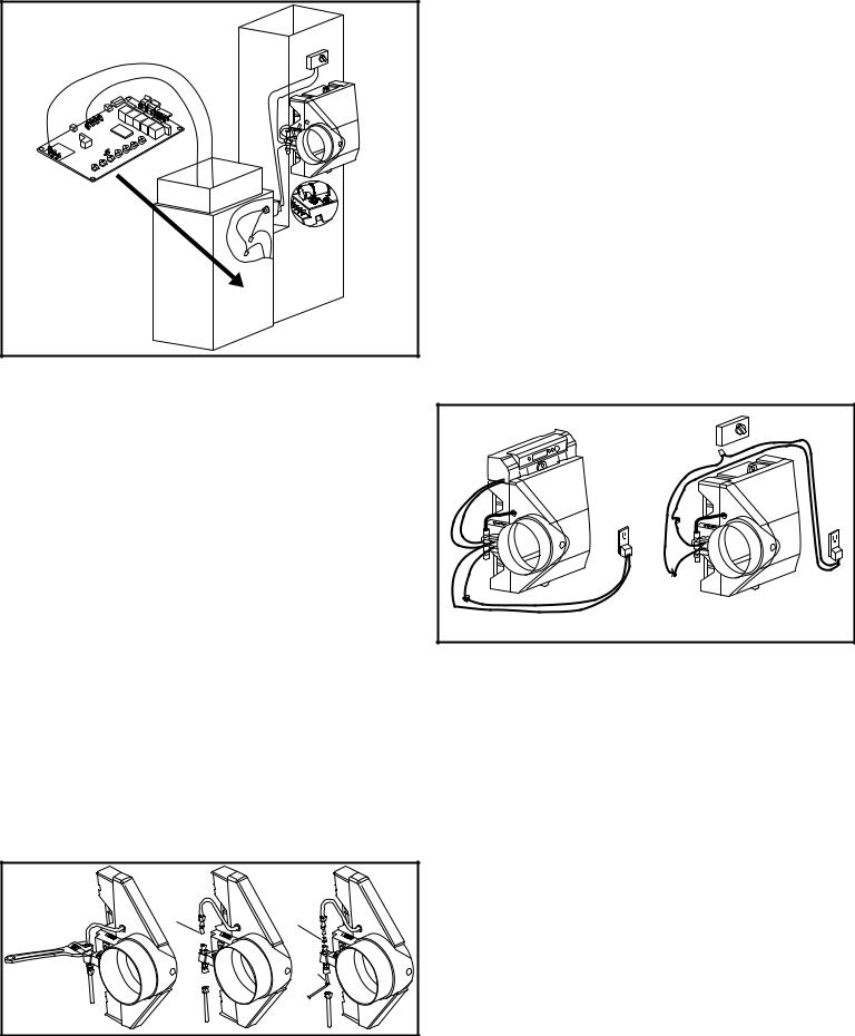
HUMIDISENSE BYPASS INSTALLATION
Connecting Humidifier to Existing Electronic Thermostat (Figure 4). This allows the existing electronic thermostat to control humidifier’s cycles.
What you will need (sold separately):
1.24 VAC NO relay, Packard PR380 (or any 24 VAC NO relay).
2.Length of two conductor solid copper thermostat wire 18 gauge max (available at most hardware stores).
3.Four 1/4” female electrical connectors (available at most hardware stores).
RELAY INSTALLATION
1.Confirm your electronic thermostat is capable of controlling a central humidifier and that it has the
necessary two conductor connections for humidity control (confirm this with the thermostat manufacturer).
2.Remove the existing humidistat from the humidifier.
Model 5000: Remove the two wires installed on the humidistat terminals.
|
|
To electronic |
|
|
thermostat |
|
|
24 V |
|
|
Relay |
|
|
C |
|
|
o |
|
|
n |
|
|
tro |
|
|
t |
|
|
Adjus |
|
|
ntrol |
|
|
seCo |
disen |
||
Humi |
|
|
3 2 |
1 |
OFF |
|
||
|
|
ON |
Figure 4 |
||
Model 6000: Disconnect the two black transformer wires from the top panel and disconnect the two red wires from the top panel to the humidifier’s side panel.
3.Mount the 24 VAC relay close to the humidifier.
4.Connect the humidifier to the 24 VAC relay.
Model 5000: Connect the two wires removed from the humidistat in Step 2 to the “Common” and “Normally Open” terminals.
Model 6000: Connect the two plug in transformer wires to the humidifier’s side panel terminals 24 VAC IN. At the relay separate the plug in transformer wires. Referring to Figure 4, cut
one of the wires, strip the ends and using the 1/4” electrical terminals connect to the relay’s “Common” & “Normally Open” terminals.
5.Using two 1/4" electrical connectors, connect the coil terminals of the 24 VAC relay to the electronic thermostat’s humidity control terminals.
6.At the humidifier, change all the DIP switches to the “ON” position and install a jumper wire across the humidisense bypass terminals #3 and #4.
HUMIDISENSE BYPASS INSTALLATION |
|
|
|
|
|
24 VAC Thermostat Interlock (Cycles |
|
|
|
|
|
humidifier whenever furnace is in heating |
New Style Board |
||||
mode and humidistat calls for humidity) |
|
|
|
|
|
(Figures 5 and 6). |
|
|
|
|
|
|
|
|
|
ls |
|
|
|
|
|
tra |
|
|
|
|
eu |
|
|
What you will need (sold separately): |
|
|
N |
|
|
|
A |
|
|
|
|
|
|
ot |
|
|
2 |
|
UM |
H |
|
|
|
|
H C |
|
UM |
1 |
|
|
EA C |
|
H |
W |
|
|
|
C |
|
|
|
|
|
|
|
|
G |
|
|
|
|
2 |
|
1. Length of two conductor solid copper |
|
|
|
Y |
|
|
|
|
1 |
|
|
|
|
|
|
Y |
|
|
|
|
|
R |
|
thermostat wire 18 gauge max |
|
|
|
|
|
(available at most hardware stores). |
|
|
|
|
|
2. Two 1/4” female electrical connectors |
|
|
|
|
G |
(available at most hardware stores). |
|
|
|
R |
|
|
|
|
C |
||
|
|
|
|
|
Y |
|
|
|
|
|
W |
24 VAC INTERLOCK INSTALLATION |
Old Style Board |
||||
|
|||||
1. Consult your furnace’s installation |
Figure 5 |
|
|
|
|
manual and or an HVAC professional. |
|
|
|
|
|
Locate the furnace’s control board |
|
|
|
|
|
normally found in the bottom portion |
|
|
|
|
|
of the furnace near the furnace blower. |
|
|
|
|
|
|
|
ls |
|
|
|
|
|
|
|
|
ra |
|
|
|
|
|
|
|
|
t V |
|
|
|
|
|
|
|
|
eu 0 |
|
|
|
|
|
|
|
|
N 1 |
|
|
|
|
|
|
|
|
2 |
|
|
|
|
|
|
|
|
|
|
|
|
|
|
G |
|
t |
|
|
|
|
|
|
Y |
|
o V |
|
|
|
|
|
2 |
|
|
H 0 |
V |
|
|
|
W |
||
UM |
2 |
|
|
|
W |
|||
1 |
4 |
|
|
|
|
|||
|
2 |
UM |
|
|
1 |
|
C |
|
H C |
|
|
|
|
||||
EA C |
H |
|
V |
W |
|
|
||
|
C |
|
|
|
4 |
|
|
R |
|
A |
|
|
|
2 om |
|
||
|
|
|
|
G |
C |
|
|
|
|
|
|
2 |
|
|
|
|
|
|
|
|
Y |
|
|
|
|
|
|
|
1 |
|
|
|
|
|
|
|
|
Y |
|
|
|
|
|
|
|
|
R |
|
|
|
|
|
|
|
|
|
C |
|
|
C |
|
|
|
o |
|
|
o |
|
|
|
n |
|
|
n |
|
|
|
t |
|
|
t |
|
|
|
r |
|
|
r |
|
|
|
o |
|
|
o |
|
|
|
olAdjust |
|
|
olAdjus |
|
|
|
Contr |
|
|
t |
Figure 6 |
|
|
|
|
Contr |
|
isense |
Humidisense |
|||||
|
Humid |
|
|
|||
|
3 2 |
1 |
OFF |
3 2 |
1 |
OFF |
|
|
|
||||
|
|
|
ON |
|
|
ON |
2.Identify the 24 volt terminals which will be energized when the furnace is in heating.
3.On older boards there will be a set of terminals used to connect to the central thermostat, these terminals are usually marked R, C, W, Y, G. On this type of board use the terminals marked C (or Com) & W (or W1).
4.On newer boards there is a dedicated 24 volt humidifier terminal marked HUM or 24V HUM. On this type of board use the 24 V Com & 24 V HUM terminals.
5.If you are unsure consult your furnace’s installation instructions and or an HVAC professional.
6.Once you have identified the proper terminals use the 18 gauge thermostat wire to make the connection from the furnace control board to the humidisense bypass terminals #1 & #2.
7.Change all the DIP switches to the ON position.
8.The humidifier will now cycle whenever the furnace heating relay is energized and the humidistat is calling for humidity.
HUMIDISENSE BYPASS INSTALLATION
Hardwired Installation. Traditional Method (Figure 7) (Model 5000 ONLY, Cycles humidifier whenever the furnace is in heating and the humidistat calls for humidity).
What you will need (sold separately).
1.Hardwire transformer 04A000200 (or other 120 Volt / 24 Volt hardwire transformer).
2.Length of white & black TEW 18 gauge wire (approx. 2ft).
3.Two 1/4” female electrical connectors (available at most hardware stores).
4.Wire Nuts & Electrical Tape.
6785015 Rev. A 7-17 |
www.airkinglimited.com |
3 of 12 |
|
|
ls |
|
|
|
|
|
|
|
|
ra |
|
|
|
|
|
|
|
|
t V |
|
|
|
|
|
|
|
|
eu 0 |
|
|
|
|
|
|
|
|
2 |
|
|
|
|
|
|
|
|
N 1 |
|
|
|
|
|
|
|
t |
|
|
|
|
|
|
|
|
o V |
|
|
|
|
2 |
|
|
|
H 0 |
V |
|
|
|
|
|
|
UM |
2 |
|
|
|
W |
|
|
|
1 |
4 |
_ |
|
|
|
|
||
|
2 |
|
|
1 |
|
|
||
H C |
UM |
|
|
|
|
|||
EA C |
H |
|
|
V |
W |
|
|
|
|
C |
|
|
|
4 |
|
|
|
|
A |
|
|
|
2 om |
|
|
|
|
|
|
|
G |
C |
|
|
|
|
|
|
|
|
|
|
|
|
|
|
|
2 |
|
|
|
|
|
|
|
|
Y |
|
|
|
|
|
|
|
1 |
|
|
|
|
|
|
|
|
Y |
|
|
|
|
|
|
|
|
R |
|
|
|
|
|
|
|
|
|
|
|
|
|
|
C |
|
|
|
|
|
|
|
|
o |
|
|
|
|
|
|
|
|
n |
|
|
|
|
|
|
|
|
t |
|
|
|
|
|
|
|
|
r |
|
|
|
|
|
|
|
|
o |
|
|
|
|
|
|
|
|
t |
|
|
|
|
|
|
|
|
olAdjus |
|
|
|
|
|
|
|
|
Contr |
|
|
|
|
|
|
isense |
||
|
|
|
|
|
|
Humid |
|
|
|
|
|
|
|
|
3 2 |
1 |
OFF |
|
|
|
|
|
|
|
||
|
|
|
|
|
|
|
|
ON |
Figure 7 |
|
|
|
|
|
|
|
|
HARDWIRE TRANSFORMER INSTALLATION
1.Consult your furnace’s installation manual and or an HVAC professional, locate the furnace’s control board normally found in the bottom portion of the furnace near the furnace blower.
2.Identify the furnace’s accessory terminals. There will be one set of terminals marked “NEUTRALS” and another set will be marked HOT, HUM, EAC.
3.If you are unsure consult your furnace’s installation instructions and or an HVAC professional.
4.Retrieve the hardwire transformer, at the bottom of the furnace locate an unused electrical knockout, remove the knockout and install and secure the transformer in the knockout. Attach the transformer so the low voltage 24 volt terminals are located on the outside of the furnace.
5.Using the black & white TEW 18 gauge wire and ¼” electrical terminals connect the white wire to one of the “NEUTRAL” terminals on the furnace board. Then connect the black wire to the 120 Volt HUM terminal on the furnace board.
6.Using the wire nuts and electrical tape connect the white & black wires installed in step 5 to the two transformer wires, secure the wire nuts with the electrical tape.
7.At the humidifier, your installation should be as per the installation instructions with the plug in transformer wired to the two terminals marked 24 VAC IN on the humidifier’s side panel with the humidistat wired into one of the transformer wires.
8.Retrieve the plug in transformer and cut the wire off at the transformer body. Separate the wires and strip the ends of the wire. Attach the ends of this wire to the 24 Volt terminals on the hardwired transformer installed in steps 5 & 6 above.
9.At the humidifier, change all the DIP switches to the ON position and install a jumper wire across humidisense bypass terminals #3 & #4.
TROUBLE SHOOTING
Humidifier seems to operate properly, green humidisense LED comes ON when furnace is in heating and the humidistat is calling for humidity but no water flows or very little water flows.
This is an indication that there is something wrong with the water supply or there is some sort of blockage in the orifice fitting, inlet water filter or the solenoid valve. Follow the directions below to check the water supply and inspect the orifice fitting & inlet water filter and clear any blockage.
Checking Water Supply, Orifice Fitting & Inlet Filter (Figure 8).
|
|
|
|
|
Orifice |
|
|
Orifice |
|
|
|
|
|
|
|
Fitting |
|
|
|
|
|
|
|
|
|
|
|
|
Fitting |
|
|
|
|
|
|
|
|
|
|
|
|
|
|
s aspBy |
1 2 |
|
3 |
|
s as py Be1 |
2 3 |
4 |
s sa py |
1 2 |
3 4 |
|
esen |
isd |
|
4 |
|
sn esi id |
|
Be sn |
||
|
|
|
mi uH |
|
|
mu H |
|
|
isemdi uH |
|
|
|
|
|
|
|
|
|
Inlet |
|
|
|
|
|
|
|
|
|
|
Water |
|
|
|
|
|
|
|
|
|
|
Filter |
|
|
Figure 8 |
|
|
|
|
|
|
|
|
|
|
1.Close the self-piercing needle valve installed on the cold water pipe, using an adjustable wrench remove the water supply connection from the inlet of the water solenoid valve.
2.Using a bucket to collect the water from the supply tube open the self-piercing needle valve and confirm water is flowing from the water supply tube, if water is not running with the piercing valve open, check your installation of the self-piercing needle valve and correct to get water flowing. If water is flowing from the water supply, move to step 3 below to check inlet water filter and orifice.
3.At the humidifier’s side panel, the water supply tube should already be removed, now using an adjustable wrench remove the tube which goes from the solenoid valve outlet to the humidifier’s evaporator pad.
4.CHECKING THE INLET WATER FILTER, Using something pointy like a nail, reach into the solenoid valve inlet and remove the filter, check for and clear any blockages.
5.CHECKING THE ORIFICE FITTING, The orifice is inserted into the tube which was installed on the solenoid valve outlet. It is press fit in place, remove the orifice and inspect. There is a very small pin sized hole in this fitting, if it is blocked try to clear it using a pin or other method. DO NOT drill this hole larger the purpose of the orifice is to protect against water blowing off the evaporator pad into the furnace as well as to limit the amount of water flowing to the drain. If you are unable to clear the orifice replace it, consult the parts diagram for the part number.
6.If after checking the water supply, inlet water filter and the orifice fitting there is still no water supply the solenoid valve is malfunctioning.
7.Check to ensure that the two water solenoid valve wires are connected properly to the two terminals marked 24 VAC OUT on the humidifier’s side panel.
8.If after checking the water supply, inlet water filter, orifice fitting and water solenoid valve there is still no water flow you will require a replacement solenoid valve assembly, consult parts diagram for the part number.
NOTE: Before replacing the solenoid valve which is an expensive component complete a quick test below to ensure the problem is not the voltage supply from the humidity control. Follow the directions below.
Models 6000
Models 5000
Figure 9
Solenoid Valve Quick Test (Figure 9). (Connect the plug in transformer directly to the solenoid valve to see if the valve will open and let water flow.)
1.Unplug the transformer.
2.MODEL 5000: Take the humidistat out of the circuit, remove the two terminals from the humidistat control and temporarily connect these two wires together (secure with electrical tape). At the humidifier’s side panel, Remove the two wires from the two terminals marked 24 VAC IN & remove the two solenoid valve wires from the two terminals marked 24 VAC OUT. Temporarily connect the transformer wires directly to the solenoid valve wires (use electrical tape to secure). Plug the transformer back in, if the water still does not flow you need to replace the water solenoid valve, if water now flows you need a new humidistat, check the parts list for the correct part number.
3.MODEL 6000: Take the digital humidistat out of the circuit, disconnect the two black transformer wires from the top panel. At the humidifier’s side panel remove the solenoid valve wires from the two terminals marked 24 VAC OUT. Temporarily connect the transformer wires directly to the solenoid valve wires (use electrical tape to secure). Plug the transformer back in, if the water still does not flow you need to replace the water solenoid valve, if water now flows you need a new digital top panel, check parts list for the correct part number.
TROUBLE SHOOTING
Not Enough Humidity. Humidifier Operates properly with furnace heating cycles, water flows but the humidity level is not increasing.
In Canada homes built since the year 2000 are designed to reduce moisture to protect against condensation damage this is accomplished by introducing fresh outdoor air into the home most often through the forced air heating system return duct. If you are seeing consistently low humidity readings after several weeks of operation consider moving the humidity control from the current location. On Model 5000 you can try locating the humidistat in another location on the duct or in the living space. On model 6000 you can purchase a remote sensor with 25 ft
of wire (PN 010266001) to locate the sensor elsewhere in the duct or living space. An optional
6785015 Rev. A 7-17 |
www.airkinglimited.com |
4 of 12 |
 Loading...