

TM
T LN
80000343 Issue 1 04/15
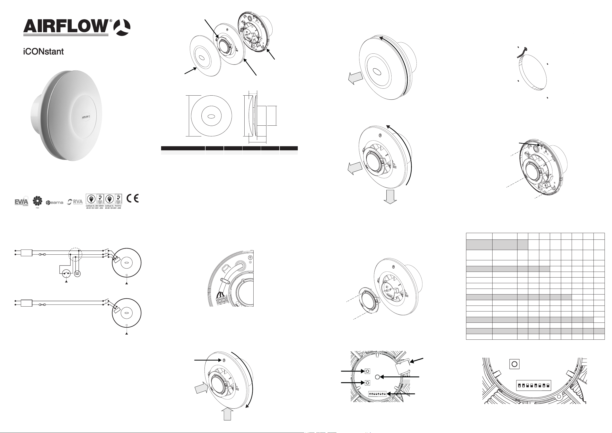
Fan overview
Installation Prepare wall or ceiling
Continuous Ventilation
Installation and Operating Guide
iCONstant T - 72687117
iCONstant HT - 72687118
Electronics Cover
Main Body
Front Cover
Fan Dimensions
A
Model A B C D E
iCONstant 197 120 70 100 50
Back Plate Cover
E
A
C
B
D
The iCONstant range consists of timer and humidity/timer
variants. They are designed for use in any wet room. Trickle
ows rates of 6, 8 or 13 l/s can be activated on installation.
Boost ow rates are selected by pull cord, external switch
or humidity sensor (HT model only). The iCONstant range is
IPX5 rated and suitable for use in Zone 1 of a wet room.
Page 2 of 16
Remove front cover.
1. Twist anticlockwise and 2. Lift away.
1
2
Remove back plate cover.
1. Remove screw at base of back plate cover.
2. Twist back plate cover anticlockwise.
3. Lift away.
2
3
1
Page 3 of 16
Using the template provided, mark and drill a spigot hole to
suit 100mm diameter rigid ducting. Make provision for the
electrical supply cable. Fit wall plugs provided.
Mount fan into the spigot hole ensuring cable is fed through
the cable grommet provided. Position alignment arrow
vertically. Fix to wall or ceiling with the 4 screws provided.
Alignment arrow
Page 4 of 16
Electrical Installation
3 AMP
3 AMP
N - Neutral
L - Live
T - Tigger
N - Neutral
L - Live
3 POLE FAN
ISOLATOR
L
N
LS
2 POLE FAN
ISOLATOR
TLN
TLN
For control with
external switching
N
RCD
L
SWITCHED FUSE
For control with no
external switching
N
RCD
L
SWITCHED FUSE
All electrical installation to be carried out by an approved
electrician in accordance with Part “P” U.K. Building
Regulations and to the latest IEEE standards, or the
appropriate regulations in the country of installation.
iCONstant fans require a 90-264V 50/60Hz supply, it is
double insulated so therefore does not require an earth.
Fans installed in Zone 1 or Zone 2 must be at least IPX4
(splash proof) rated. Additionally, fans installed in Zone 1
must be SELV (Safety Extra Low Voltage) or IPX5 (jet proof)
rated. The iCONstant range is IPX5 rated and suitable for
use in Zone 1.
Secure supply wires into the terminal block. L—Live,
N-Neutral and T—switched live (optional). Secure AC mains
cable to main body of fan with cable clamp supplied.
Fit back plate cover.
1. Locate back plate cover on to main body assembly.
2. Twist back plate cover clockwise until locked. (Arrow
should be in the 12 o’clock position).
3. Secure back plate cover with xing screw.
Alignment Arrow
2
1
3
Page 6 of 16Page 5 of 16
Access to the electronics Dip switch functions
Remove electronics cover.
1. Undo the 2 xing screws,
2. Lift off electronics cover.
Description of electronic controls.
Increase airow
Decrease airow
ON
OFF
Page 7 of 16
Humidity sensor
(HT model only)
Info LED
Function
Dip Switches
Function 1 2 3 4 5 6 7 8
Delayed
start
Delayed
start
Timer 2 mins
Timer 15 mins
Timer 30 mins
Timer 45 mins
Humidity 50-60%
Humidity 60-70%
Humidity 70-80%
Humidity 80-90%
Flow rate
Flow rate
Flow rate
Flow rate
Flow sensor
Flow sensor
0 seconds
2 minutes
OFF OFF OFF
6 L/s OFF ON
8 L/s ON OFF
13 L/s ON ON
ON ON
OFF OFF
Dip Switch factory settings highlighted above.
OFF
ON
OFF OFF
OFF ON
ON OFF
ON ON
OFF OFF
OFF ON
ON OFF
ON ON
ON
OFF
Page 8 of 16
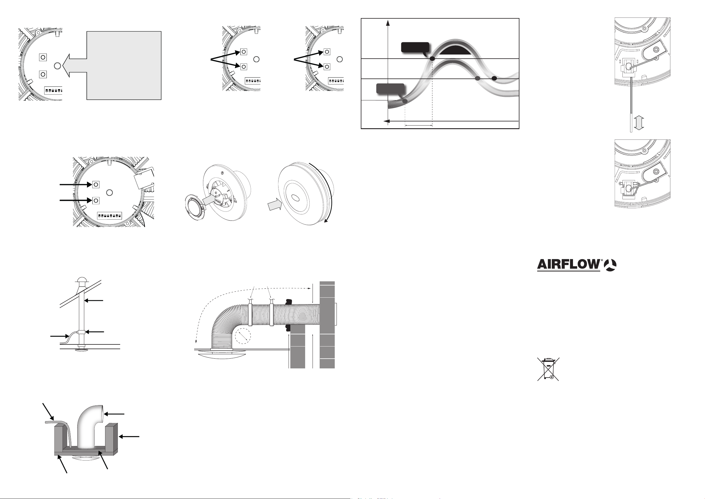
Store new ow rate
Restore selected dip switch
ow rate
Humidity function (HT model only) Boost activationStart up diagnostic sequence
On connection to the
power supply the fan
will run a diagnostic
sequence. This is
indicated by the LED
ON
OFF
ashing 6 times. The fan
will automatically start.
Commissioning adjustment
To adjust the airow rate on commissioning, press top button
to increase ow rate, press bottom button to decrease ow
rate.
Increase airow
Decrease airow
ON
OFF
Press & hold
both for 5
seconds.
LED will
ash
once for
conrmation
ON
OFF
Press & hold
both for 10
seconds.
LED will
ash
twice for
conrmation
ON
OFF
Fit electronics cover and secure with the 2 xing screws.
Check the fan is running. If the LED is on permanently check
installation for impeller obstructions and resolve. Replace
the front cover and twist clockwise to secure.
Page 10 of 16Page 9 of 16
RELATIVE HUMIDITY
Upper Limit - Fan On
Fan Off
iCONstant
HT On
Conventional
Humidity On
iCONstant
Pre-Start
Phase
Mould/
Condensation
will occur
TIME
Automatic Humidity Control with a progressive increase in
humidity—the fan will boost when the pre-set value (factory
setting 70-80% RH) is reached. However, when the sensor
detects a rapid increase in humidity the fan will boost
automatically before the pre-set value has been reached so
that preventive ventilation commences. The fan reverts to
trickle automatically when the humidity is reduced to 10%
below the set point. Note: It is possible that a high level
of humidity is present within the room for a longer period
of time due to generally high humidity in the ambient air
(summertime) or a build up of high humidity over several
hours (steam rooms/sauna etc.)
Page 11 of 16
Pull Cord or switched live
activation increases the
trickle ow rate to boost
for the selected timer
period.
From 6 l/s trickle to 8 l/s
From 8 l/s trickle to 13 l/s
From 13 l/s trickle to 20 l/s
Pull cord storage
Wrap and store around
stowaway mechanism
if not required
Delayed start
The delayed start function of the fan to its’ boost function is
only activated by a remote switch and not by the pull cord.
Page 12 of 16
Good practice guide MaintenanceInstallation with exible ducting
Installation in the ceiling.
Flexible
ducting supports
Minimum radius =
the diameter of
flexible ducting used
Page 14 of 16Page 13 of 16
110mm diameter
plastic pipe
outlet drain to
the outside
To avoid the back ow of condensation into the fan in the
ceiling installations it is good practice to t a condensation
trap (optional—Airow Part 51978301) to the vertical outlet
duct of the fan.
possible cable routing
duct
joist
plywood
ceiling
Maximum length of
flexible ducting
Airflow
Where exible ducting is used the diameter must be
maintained and it is good ventilation practice that the
ducting is extended to 90% of its possible length in order to
maintain the best possible airow. Ensure that exible duct
connections are not over tightened to the fan outlet spigot.
To avoid reduced air ow rigid ducting should be used
(see airow.com). The fan and ducting should be installed
in accordance with the requirements of the Domestic
Ventilation Compliance Guide, part of the
Building Regulations.
Sealant
Slope to outside
Cavity
SAFETY FIRST: ALWAYS ISOLATE THE FAN UNIT FROM THE
POWER SUPPLY BEFORE REMOVING THE COVERS. When
installed according to these instructions the iCONstant is completely
safe. The materials used do not constitute a hazard.
Cleaning
The external housing of the fan can be wiped with a damp cloth.
Do not use household cleaners containing abrasives. Note: Always
isolate the fan when cleaning. Never clean any parts of the fan
assembly by immersing in water or using a dishwasher.
Warranty
Applicable to units installed and used in the United Kingdom.
Airow guarantees the iCONstant for 3 YEARS from date of
purchase against faulty material or workmanship. Warranty only
covers the fan, not the re-installation of the fan if required. In the
event of any defective parts being found, Airow Developments Ltd
reserve the right to repair or at our discretion replace without charge
provided that the unit:
1. Has been installed and used in accordance with the tting and
wiring instructions supplied with each unit.
2. Has not been connected to an unsuitable electrical supply.
3. Has not been subjected to misuse, neglect or damage.
4. Has not been modied or repaired by any person not authorised
by Airow Developments Ltd.
5. Has been installed in accordance with latest Building Regulations
and IEEE wiring regulations by a recognised competent installer.
Page 15 of 16
Warranty cont’d
Airow Developments Ltd shall not be liable for any loss, injury
or other consequential damage, in the event of a failure of the
equipment or arising from, or in connection with, the equipment
excepting only that nothing in this condition shall be construed as to
exclude or restrict liability for negligence.
This warranty does not in any way affect any statutory or other
consumer rights.
Disposal
Do not dispose of with household waste.
Please recycle where facilities exist.
Check with your local authority for recycling advice.
UK Head-Ofce
AIRFLOW DEVELOPMENTS Limited
Aidelle House, Lancaster Road
Cressex Business Park
High Wycombe
Buckinghamshire
HP12 3QP
United Kingdom
Tel: +4(0) 1494 525252
Fax: +4(0) 1494 461073
Email: info@airow.com
Web: airow.com
AIRFLOW DEVELOPMENTS Limited reserve the right in the interest of continuous development to alter any or all
specications without prior notice.
Czech Republic
AIRFLOW LUFTTECHNIK GmbH
o.s. Praha
Hostýnská 520
108 00 Praha 10
Malešice
Czech Republic
Tel: +42(0) 2 7477 2230
Fax: +42(0) 2 7477 2370
Email: info@airow.cz
Web: airow.cz
Page 16 of 16
Germany
AIRFLOW LUFTTECHNIK GmbH
Postfach 1208
D-53349 Rheinback
Germany
Tel: +49(0) 222 69205 0
Fax: +49(0) 222 69205 11
Email: info@airow.de
Web: airow.de
 Loading...