

Airflow 9041353, 9041352, 9041351, Aura eco-air 100, Aura eco-air 150 Installation Instructions
Page 1

9041411
INSTALLATION & OPERATING INSTRUCTIONS
100mm & 150mm Axial Fans
Aura-eco
Page 2
Introduction
This Service Instructions are combined with technical specification, operating guide
and specification for the “Aura-eco ” fan; it contains information on installation, that
are important for ensuring correct and safe operation of the fan.
Designation
Fans are designed for ventilation of domestic and similar premises
(apartments,offices,stores,garages,kitchens, bathrooms, toilets and other
rooms, heated in wintertime).
Fans are exhaust fans and are designed for wall or ceiling mounting
(Fig.6,7). They are designed for a long-duration operation, without
disconnection from the power network.
The fan design is being constantly improved therefore some models may
slightly vary from those described in the present specification.
Set of supply
The following article is included:
- Fan 1pc;
- User's manual;
- Screws 4 pcs.
- Packing box
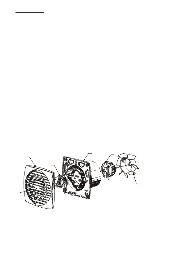
The fan arrangement with the timer or with a timer and a humidity sensor is
shown at the Fig. 1
1
5
2
3
4
Fig.1
1-cover, 2-casing, 3-electric
motor 4-blade impeller, 5-timer.
Page 3
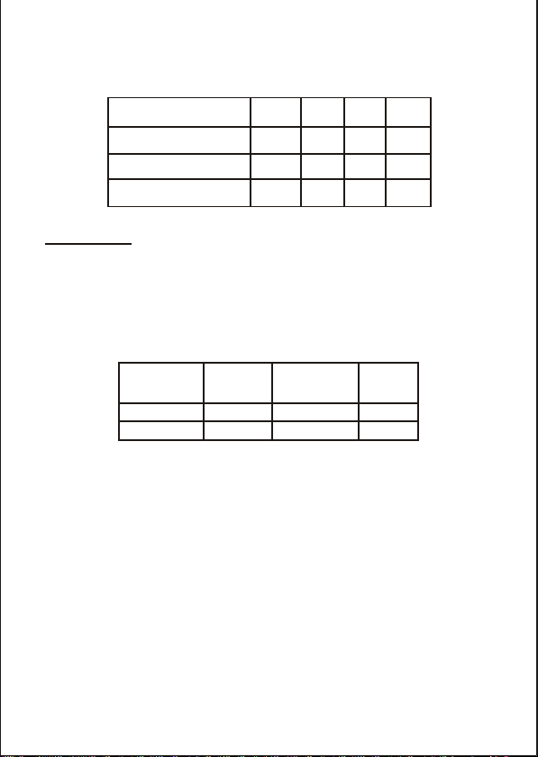
The options arrangement of the fans is given in the table 1.
Table 1
B
T
HT
PRT
Adjustable
timer (2-30) minutes
Timer with
humidity sensor
Timer with
motion sensor
Table 2
Max. Max.
Nominal
Noise
air intake,
pressure,
power,
level,
m
3
/h
Pa
W
dBA 60
35
6
26
235
86
20
35
Key features
The fans' designation, their characteristics, appearance, overall and
connection dimensions are listed in the tables 2,3 and at the Fig. 1,2.
The fans are designed for the connection to the AC network with the
voltage of 220-240 V and current frequency of 50 Hz.
The fans are designed for use in the premises with
temperature from 0°C to 45°C.
The fans do not interfere with radio, television and video
equipment.
Page 4
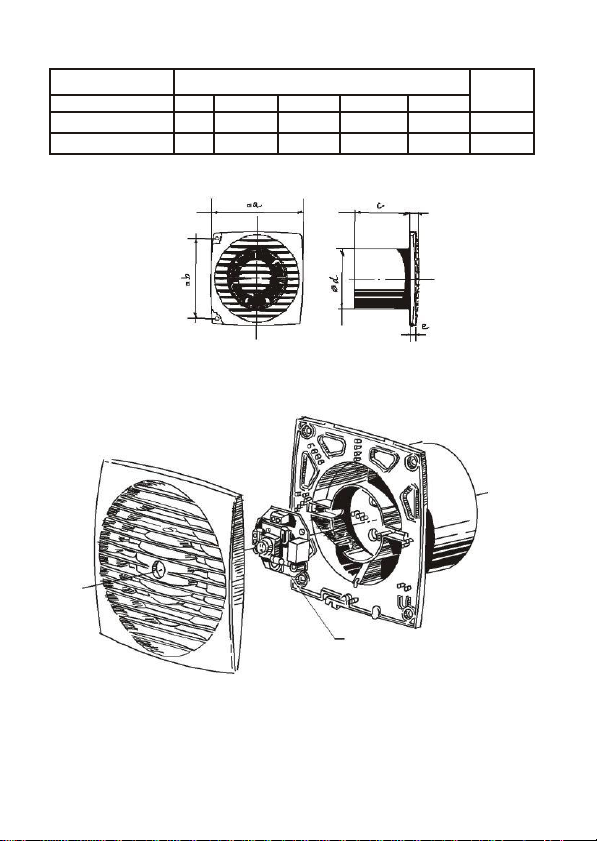
Table 3
Type
Dimensions,
Weight,
a b c d
e
kg
Aura eco-air 100
150
122
102
100
17
0,56
Aura eco-air 150
205
174
124
150
19
0,9
Overall and connection dimensions
Fig.
2
1
1- Timer with motion sensor
Fig.
3
Page 5
SAFETY REQUIREMENTS
The fan “Aura-eco” complies with the requirements according to the EU
norms and directives.
Level of protection from access to hazardous parts and waterproof is to
IPX4
Connection of fans supplied with the electric cords to power supply as well as
replacement of electric cord should be perfomed by a competent person
(Part P) and in accordance with latest IEE wiring regulations. A 3 amp fused
isolator should be fitted.
Fan operation beyond the operational temperature range as well as in rooms
with ambient air containing aggresive mixture is prohibited.
Precautions must be taken to avoid the black -flow of gases into the room
from the open flue of gas or other fuel-burning appliances.
Attention:
Ensure impeller rotates freely. Do not overtight on
ductwork connections to fan spigot.
Precautions must be taken to avoid the black -flow gases
into the room from the open flue of gas or other fuel-
burning appliances.
PREPARATION OF DEVICE OPERATION
Attention: All work must be carried out with the equipment fully
All relevant safety regulation, national standards and norms are to be adhered
to. An appliance is required for cut off from the supply with a minimum of 3mm
contact opening of each pole.
The rated voltage and frequency must correspond with the data on the type
plate. The insertion of mains supply cable is carried out via a cable grommet
which is included in the delivery. Never lead cable over sharp edges. The
equipment corresponds to protection IPX4.
isolated from the power supply. The electrical connection
is to be carried out in accordance with the relevant wiring
diagram and are only to be done by a certified electrician.
The electrical connection must be fully isolated from the
supply up to the final assembly!
Page 6
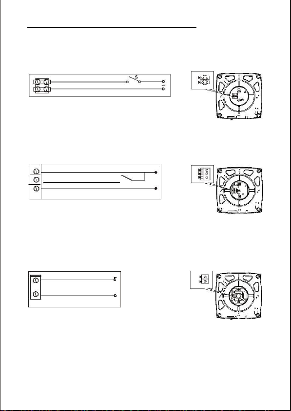
Diagrams of the connection to electric supply
Diagram of the connection of “Aura-eco” fan
without built-in switch, where B is an
external switch
L
LT
N
Diagram of the connection of “Aura-eco” fan
with timer / timer with humidity sensor, with
built-in switch
L
N
Diagram of the connection of “Aura-eco”
fan with timer / timer with motion
sensor, without built-in switch
L
N
connection of
“Aura-eco” fan
100/150 B
L
LT
N
connection of
“Aura-eco” fan
100/150 T, HT
L
N
connection of
“Aura-eco” fan
100/150 PRT
Page 7
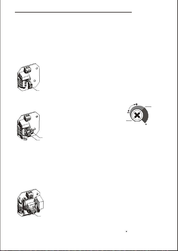
USER MAINTENANCE AND SENSOR ADJUSTMENT
90%
The fan with timer and humidity sensor
switches on when voltage is supplied to
60%
clamp LT or when the definite humidity
H min
H extreme
level ( regulated from 60% till 90 %) is
right
exceeded. After the voltage is
position
T
disconnected or humidity level H is decreased, the fan continues
H
working during the time set by timer T, which is regulated from
Fig. 5.2
2 till 30 min. The options of time T and humidity H are regulated
by turning the potentiometers T and H clockwise to increase and
anticlockwise to decrease the delay time and humidity level
T
regulated by turning the potentiometers clockwise to increase
Fig. 5.3
and anticlockwise to decrease the delay time (Fig. 5.3)
Before starting work ensure the fan is disconnected from the power
supply.
Cleaning should be done with a soft cloth wet with soap solution; after that, the
surfaces should be rubbed dry. The blades of the fan need careful cleaning
each 6 months. For this purpose, it is necessary to take the blade wheel off the
motor shaft (holding it by the boss). The blades should be cleaned with solution
of water and a detergent. Please avoid water entry on the motor.
Fig. 5.1
respectively. To set the maximum humidity level the potentiometer H has to
be set in position H max (90%).
Attention! If during the regulation the potentiometer H is set outside of the
indicated zone rightwards from H max there is a probability that the fan will
not switch on. In this case, it is necessary to check the position of the
potentiometer (Fig. 5.2).
The fan with timer options switches on when the voltage is
supplied to clamp LT. After the voltage is disconnected the
fan continues working during the time T, which is regulated
from 2 till 30 minutes. The time T is regulated by turning the
T
potentiometer clockwise to increase and anticlockwise to
decrease the delay time (Fig. 5.1)
H max
The fan with the timer and movement sensor switches on
when a person moves at the distance from 1 till 4 meters with
viewing angle of the sensor of 100° horizontaly. After the person
stops moving the fan continues working during the set time T,
which is regulated from 2 till 30 minutes. The time T is
Page 8
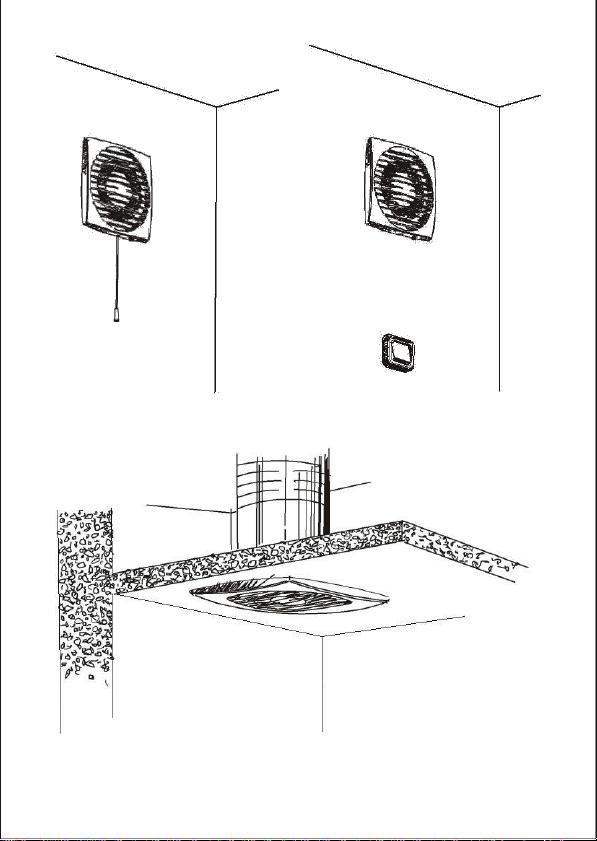
Fig. 6
Fig. 7
Page 9
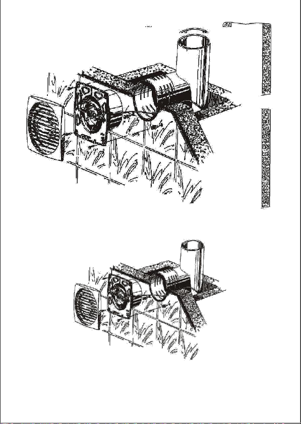
Fig. 9
Page 10
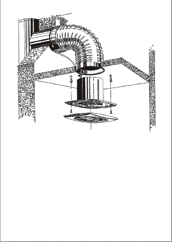
Fig. 10
Page 11

Warranty:
Applicable to units installed and used in the United Kingdom
Airflow guarantees the Aura eco-air for 2 years. The guarantees can be
upgraded to 3 years upon registering on our website airflow.com from date of
purchase against faulty material or workmanship.
In the event of any defective parts being found, Airflow Developments Ltd reserve the
right to repair or at our discretion replace without charge provided that the unit
1. ) Has been installed and used in accordance with the fitting and wiring
instructions supplied with each unit.
2. ) Has not been connected to an unsuitable electrical supply.
3. ) Has not been subjected to misuse, neglect or damage.
4. ) Has not been modified or repaired by any person not authorised by
Airflow Development Ltd
5. ) Has been installed in accordance with Building Regulations
(IEE wiring regulations).
Airflow Developments shall not be liable for any loss, injury or other
consequential damage, in the event of a failure of the equipment or arising from
or in connection with the equipment excepting only that nothing in this condition
shall be construed as to exclude or restrict liability for negligence.
This warranty does not in any way affect any statutory or other
consumer rights
Airflow Developments Ltd
Aidelle House, Lancaster Road
Cressex Business Park
High Wycombe
Bucks. HP12 3QP
Tel: +44 (0) 1494 525252
Fax: +44 (0) 1494 461073
E-mail: [email protected]
Web: airflow.com
 Loading...