

Page 1
80000439 Issue 1 06/18
SELV 12V Fan Range
Installation and Operating Guide
iCON 15S – 72683701
iCON 30S – 72683801
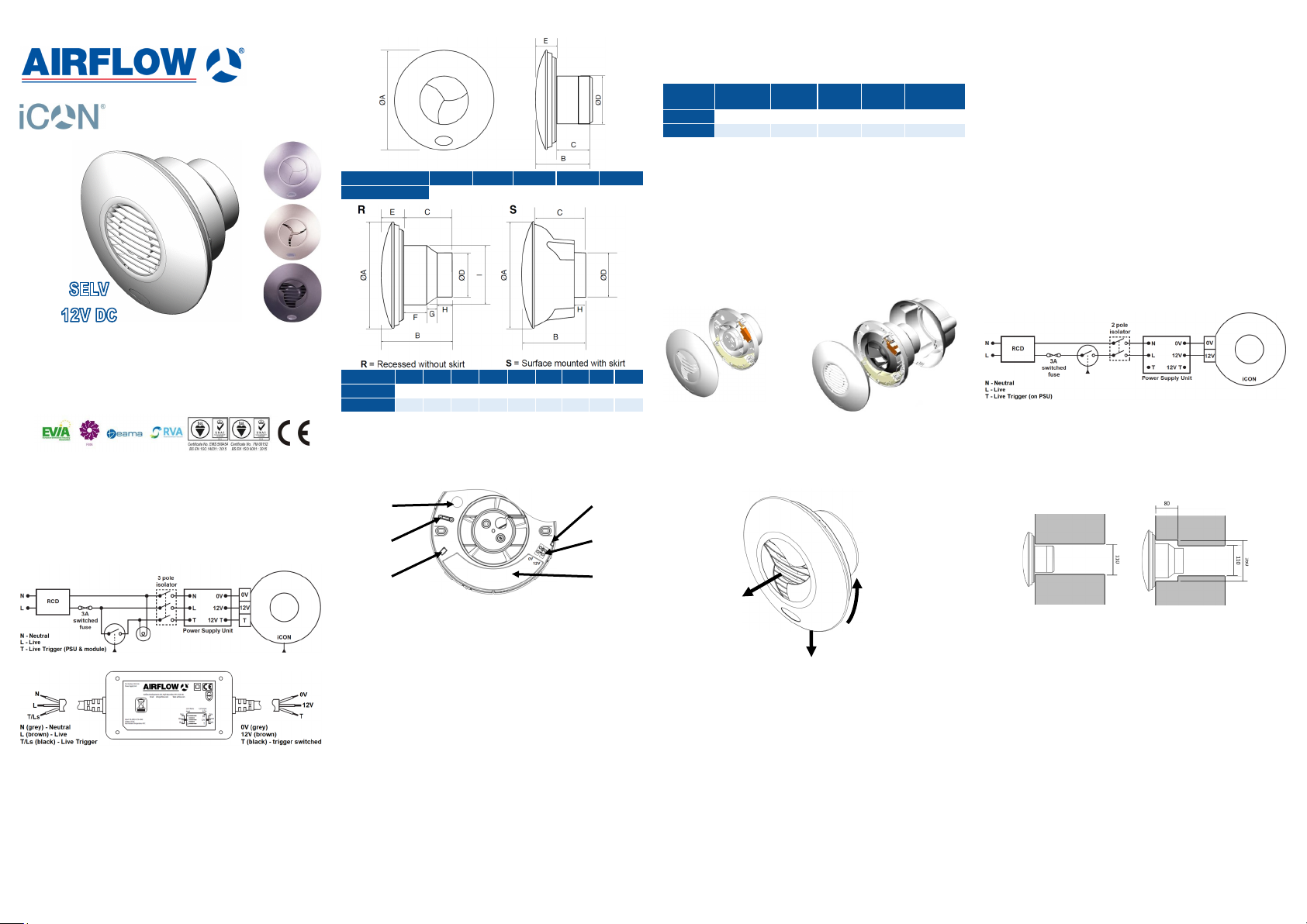
Fan dimensions
Model A B C D E
iCON 15S 197 108.5 67.5 100 40
Model A B C D E F G H I
iCON 30 (R) 225 144 101 97 43 51 20 30 148
iCON 30 (S) 225 144 92 97 - - - 29 -
Page 2 of 16
Range overview
Airflow® iCON® SELV range are 12V DC powered Safety
Extra Low Voltage fans. Fans are available in two model
sizes and can be fitted to a wall or ceiling.
Part no. Model
72683701 i CON 15S 21 / 77 6.1 0.07 32.4
72683801 i CON 30S 37 / 132 12.2 0.10 36.2
Air flow
[l/s / m3/h]
iCON 15S -100mm axial fan
iCON 30S -100mm mixed-flow fan
The iCON SELV range can be used as a simple extract
SELV fan operated by a remote switch (standard), or can
be fitted with an internal control module to give a range of
control options (which includes: timer, humidity, motion sensor,
pull cord or combinations of these functions).
These optional modules are available separately and can be
fitted at the time of installation or retrofitted (see page 15).
iCON 15S iCON 30S
Page 3 of 16
Power
[W]
Current
[A]
Noise level
[dB(A) @ 3m]
Electrical installation
All electrical installation must be carried out by an approved
electrician in accordance with Approved Document Part P of
U.K. Building Regulations and to the latest IET standards, or
the appropriate regulations in the country of installation.
The fan requires a 12V DC supply (included in the box),
class III equipment (marked as st ated in BS EN 60417).
The iCON SELV fan range is IPX4 rated and therefore it is
suitable for mounting in bathrooms (incl. zones 1 and 2), toilets, kitchens and utility rooms, as long as it is not exposed to
water jets (i.e. can be installed above fixed shower head).
Switches for fans shall be selected and sited in accordance
with BS7671 (IET Wiring Regulations) or relevant.
Important
Do not place the ventilator near direct heat sources, e.g. radiant heaters, or where temperatures can exceed 40°C (104°F).
Wiring with no control module fitted:
Page 4 of 16
Electrical installation
Optional modules for iCON SELV 12V
Wiring and installation of iCON modules can be found in the
Instructions included within the module packaging.
Wiring for control modules with external switching:
Power Supply Unit (PSU, included in the box)
The power supply unit requires 100-240V 50/60Hz supply
(class II). It is self resetting for over current and short circuit
protection. An external 3A fuse and 30mA RCD is required for
each unit. The LED indicator shows the unit is switched on.
The power supply unit must be fitted outside of wet zones
(usually outside of the room). The maximum length of wire
between the unit and the fan should not exceed 5 meters
using 1.5mm2 wire. Never cover the power supply unit with
thermal insulation materials.
Page 5 of 16 Page 6 of 16
Mechanical installation
Module clip Cable entry
Cable clamp
Module
locating block
iCON fans can be recessed in a wall or ceiling (iCON 30S is
also supplied with surface mounting kit). See pages 8-10 for
details.
Always ensure free running of the fan impeller and that duct
connections are not over tightened to the fan outlet spigot.
Fix the sealed grommet supplied into the cable entry hole.
Pierce the grommet to allow the mains cable to be pulled
through while maintaining the integrity of the seal.
Airflow Developments recommends that rigid ducting is used
where possible instead of flexible ducting, this will ensure
maximum performance.
Before carrying out the installation see pages 11&12 for
best practise recommendations.
Important
Precautions must be taken to avoid the back-flow of gases into
the room from the open flue of gas or other fuel-burning appliances.
Terminal
connector
Module fitting
place
Front cover removal
3
To remove front cover assembly, first make sure the fan is off,
isolated from the power supply and the iris shutter is fully
closed.
1. Undo the locking screw at the bottom edge of the cover
using a screwdriver.
2. Rotate the cover a few degrees anticlockwise until it clicks
out from the fittings.
3. Remove the cover by pulling it out.
To refit the cover, reverse the above procedure. If when refitting the front cover the iris stays open, remove the cover and
don’t attempt to refit it for approx. two minutes (allowing the
actuator to retract back in the closed position). Then try again.
Page 7 of 16
2
1
Fitting on the wall
iCON 15 iCON 30 (R)
Recessing fans in the wall
The iCON 15S requires a 110mm diameter hole through the
wall lined with a 100mm internal diameter duct.
The iCON 30S requires a 110mm diameter hole through the
wall, counter bored 160mm to a depth of 80mm. The hole
should be lined with a 100mm internal diameter duct.
Surface mounting fans on the wall
When surface mounting the iCON 30S the supplied mounting
skirt should be used.
The iCON 30S requires a 110mm diameter hole through the
wall lined with a 100 mm internal diameter duct.
Ensure all vapour barriers are properly restored.
Page 8 of 16
Page 2
Fitting in the ceiling
When recessing or surface mounting fans in the ceiling, a
plywood support (min. 18mm thick) should be mounted be-
tween the ceiling joists. Any fixing screws should be fitted
through the plaster board into the support.
Important
Fans should not be fitted to unsupported plaster board.
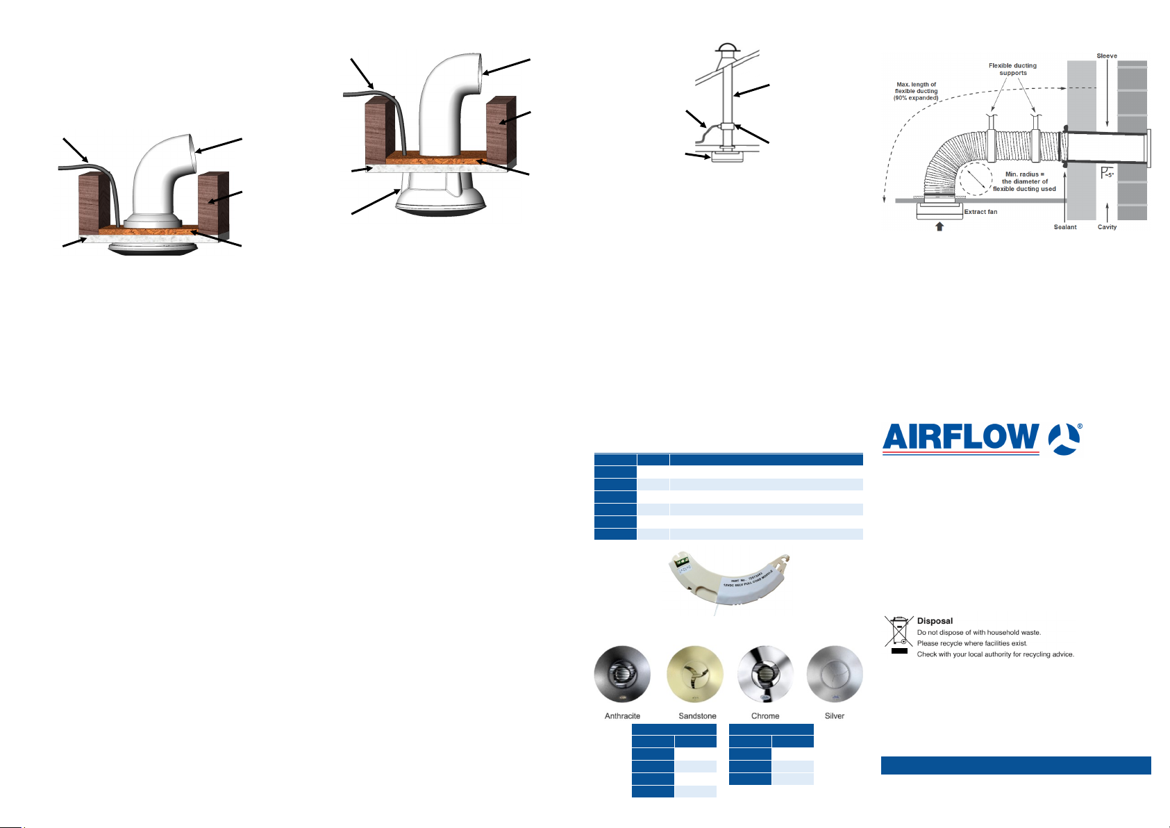
Recessing fans in the ceiling
Possible cable
routing
Ceiling
The fan should be fitted in the hole, fixed with the screws
provided into the support.
The iCON 15S requires a 110mm diameter hole through the
ceiling.
The iCON 30S requires a 160mm diameter hole through the
ceiling.
Where flexible duct is used the diameter must be maintained.
Page 9 of 16
Duct
Joist
Plywood
Fitting in the ceiling
Surface mounting fans on the ceiling
Possible cable
routing
Ceiling
Mounting skirt
When surface mounting the iCON 30S, the mounting skirt
provided should be used. The mounting skirt should be fixed,
with the screws provided, into the support. The fan is then
fitted into the skirt.
The iCON 30S requires a 110mm diameter hole through the
ceiling.
Where flexible duct is used the diameter must be maintained.
Page 10 of 16
Duct
Joist
Plywood
Best practise recommendations
Condensation
Outlet drain to
the outside
To avoid the backflow of condensation into the fan in ceiling
installations it is good pract ice to fit a condensati on trap
to the vertical outlet duct of the fan. With thru-the-wall instal-
lation fit th e duc t in an approx. 5° angle down to outside.
Fan
Measurements and commissioning
The Building Regulations 2010, Statutory Instrument Part 9,
§42, imposes a requirement that testing and reporting of me-
chanical ventilation performance (see Approved Document F1)
is conducted in accordance with an approved procedure.
Compliance with this requirement by an assessed and registered ‘Competent Person’ should follow a ‘Best Practise’ process and adopt air flow measurement, Method A - The Unconditional Method - using a suitable UKAS certified measuring
instrument. Generically referred to as ‘Zero Pressure Air Flow
Meter’ or ‘Powered Flow Meter’.
Further information on this method is detailed in NHBC Building Regulations Guidance Note G272a 10/13 and BSRIA
Guide document BG 64/2016.
Page 11 of 16
Plastic pipe
Condensation
trap
Best practise recommendations
Installation with flexible ducting
Where flexible ducting is used the diameter must be maintained and it is good ventilation practice that the ducting is
extended to a minimum of 90% its possible length in order to
maintain the best possible air flow.
Ensure that flexible duct connections are not over tightened to
the spigots.
To maximise the air flow rigid ducting should be used where
possible. The fan and ducting should be installed in accordance with the requirements of the Domestic Ventilation Com-
pliance Guide, part of the Building Regulations.
Page 12 of 16
Maintenance
SAFETY FIRST: ALWAYS ISOLATE THE FAN UNIT FROM
THE POWER SUPPLY BEFORE DOING ANY WORK ON
THE FAN/MODULE.
When installed according to these instructions the iCON range
is completely safe. The materials used do not constitute a
hazard.
Cleaning
Fan and ducting should be inspected and cleaned on a
regular basis to keep fan performance. The ext ernal hous-
ing of the fan can be wiped with a damp cloth. Do not use
household cleaners containing abrasives. Cleaning of the
internal parts such as the impeller should be carried out by
using a soft brush. Never clean any parts of the fan assembly
by immersing in water or using a dishwasher.
Warning
This appliance can be used by children aged from 8 years and
above and persons with reduced physical, sensory or mental
capabilities or lack of experience and knowledge if they have
been given supervision or instruction concerning use of the
appliance in a safe way and understand the hazards involved.
Children should not play with the appliance. Cleaning and user
maintenance shall not be carried out by children without adult
supervision.
Page 13 of 16
Warranty
Applicable to units installed and used in the United Kingdom.
Airflow Developments Ltd guarantees the iCON for 3
years from date of purchase against faulty material or
workmanship. You c an register your warranty on-line (for
more information check at www.airflow.com). Warranty only
covers the fan, not the reinstallation if required. In the event of
any defective parts being found, Airflow Developments Ltd
reserve the right to repair or at our discretion replace without
charge provided that the unit:
1. Has been installed and used in accordance with the fitting
and wiring instructions supplied with each unit.
2. Has not been connected to an unsuitable electrical supply.
3. Has not been subjected to misuse, neglect or damage.
4. Has not been modified or repaired by any person not au-
thorised by Airflow Developments Ltd
5. Has been installed in accordance with latest Building Regu-
lations and IET wiring regulations by a recognised competent installer.
Airflow Developments Ltd shall not be liable for any loss, injury
or other consequential damage, in the event of a failure of the
equipment or arising from, or in connection with the equipment
excepting only that nothing in this condition shall be construed
as to exclude or restrict liability for negligence.
This warranty does not in any way affect any statutory or other
consumer rights.
For detailed standard warranty terms and conditions see
our website or contact Customer Service.
Page 14 of 16
Options
Optional control modules available for iCON SELV 12V
Part no. Mo del Description
72573603 PCS
72574204 PCTS
72682307 DTS
72574202 HTS
72574203 PRTS
72574201 PRHTS
Choose from optional colour covers
Pull cord (manual on/off)
Pull cord timer (overrun 1-30 min)
Delayed timer (2 min delay, overrun 2 -45 min, pull cord)
Humidity timer (40-90% RH, overrun 1 -30 min, pull cord)
PIR timer (motion sensor, overrun 1-30 m in)
PIR with humidity timer (motion sensor, 40 -90% RH, overrun 1-30 min)
Covers for iCON 15S
Part no. Colour
52634503B Anthracite
52634505B Sandstone
52634504B Silver
52634502B Chrome
Covers for iCON 30S
Part no. Colour
52634506B Anthracite
52634508B Sandstone
52634507B Silver
Page 15 of 16
UK Head-Office
AIRFLOW DEVELOPMENTS Ltd
Aidelle House, Lancaster Road
Cressex Business Park
High Wycombe
Buckinghamshire
HP12 3QP
United Kingdom
Tel: +44 (0) 1494 525252
Email: [email protected]
Web: www.airflow.com
© Airflow Developments Ltd.
Airflow Developments Limited reserve the right, in the interests of continuous development, to alter specifications without prior notice. All orders are accepted subject to our
conditions of sale which are available on request.
Czech Republic
AIRFLOW LUFTTECHNIK GmbH
o.s. Praha
Hostýnská 520
108 00 Praha 10
Malešice
Czech Republic
Tel: +42 (0) 2 7477 2230
Email: [email protected]
Web: www.airflow.cz
www.airflow.com
Germany
AIRFLOW LUFTTECHNIK GmbH
Postfach 1208
D-53349 Rheinbach
Germany
Tel: +49 (0) 222 69205 0
Email: [email protected]
Web: www.airflow.de
 Loading...