

Page 1
0408
Video Demodulator for the
KC, GF, GH, JA, JF, MK & MY Series Video Systems
- INSTRUCTIONS -
The KCW-D/B adaptor converts the 2-wire video signal from the KC, GF,GH, JA, JF, MK & MY systems
to a standard composite video output signal. This allows the image from the door station to be seen on a
standard CCTV monitor or TV (video input). The video image can also be recorded if connected into a
VCR, DVR, or other recording device.
WIRING DIAGRAMS:
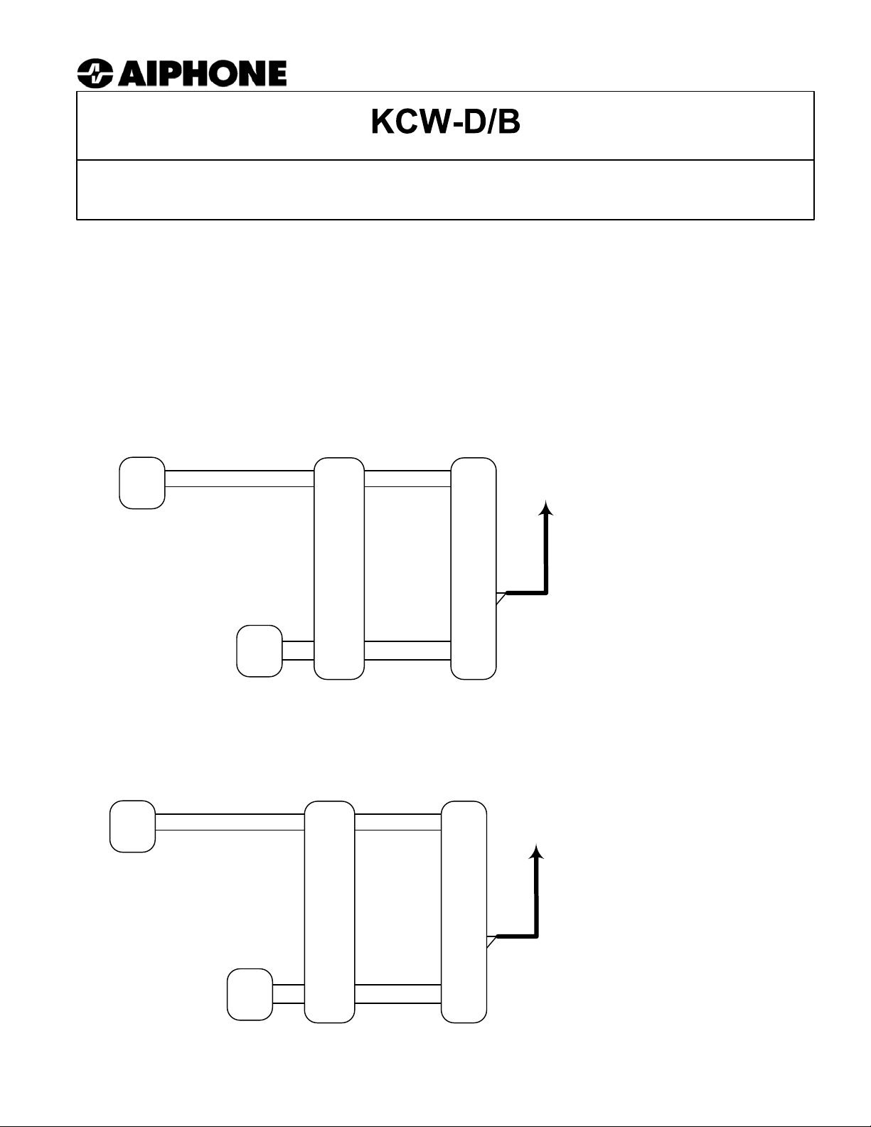
KCW-D/B for Composite Video Output from a KC Monitor
KC-1GRD/
KC-DAR
A1
A2
KC-1HRD
1A1
1A2
KCW-D/B
DA1
DA2
Composite
video output
b
E
DV+
+
-
Center to DV+
Braid to DV-
PS-2420UL
+
-
DV-
+
-
KCW-D/B for Composite Video Output from a JF-1MD Monitor
JF-DA*
A1
A2
* JF-DV or JF-DVF
can also be used.
PS-1820UL
JF-1MD
1A1
1A2
KCW-D/B
DA1
DA2
b
E
DV+
DV-
Composite
video output
Center to DV+
Braid to DV-
KCW-D/B TERMINAL DEFINITIONS:
DA1/DA2 2-Wire input from KC monitor
DV+ Coax output: Center conductor
DV- Coax output: Braided shield
b Not functional
E Not functional
+ Positive 24V DC
- Negative
Output Signal:
75 ohm, 1V peak-to-peak.
Coax: Solid copper core with copper braid.
+
-
+
-
+
-
Pg. 1
Page 2
WIRING DIAGRAM:
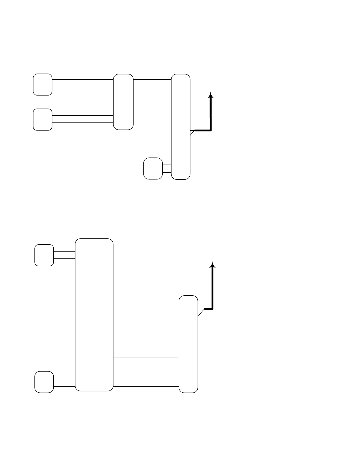
KCW-D/B for Composite Video Output when any GF/GH monitor is active
Method 1: Connecting KCW-D/B to a specific monitor
GF-VBC/GF-4Z
GH-VBC/GH-4Z
B1
B2
GF-BC/GH-BC
R1
R2
GF-1MDK
GH-1KD
B1
B2
R1
R2
24V DC
+
-
KCW-D/B
DA1
DA2
DV+
DV-
+
-
Composite
video output
Center to DV+
Braid to DV-
KCW-D/B TERMINAL DEFINITIONS:
DA1/DA2 2-Wire input from GF Monitor
DV+ Coax output: Center conductor
DV- Coax output: Braided shield
b Not functional
E Not functional
+ Positive 24V DC
- Negative
Output Signal:
75 ohm, 1V peak-to-peak.
Coax: Solid copper core with copper braid.
Notes:
1.Since the video signal is common throughout the system, video will be present from the KCW-D/B when
any GF-1MDK or GH-1KD monitor is on.
2. Any 24V DC, 1A power supply can be used to power the KCW-D/B (Aiphone PS-2410A or other).
Method 2: Connecting KCW-D/B directly to GF-VBC / GH-VBC video bus control unit
GF-VBC/A / GH-VBC
GF-VA / GH-VA
A1
A2
In 2
In 4
In 5
PS-2410LC
+
-
Out 1In 1
A1 B1
A2 B2
Out 2
A1 B1
A2 B2
Out 3In 3
A1 B1
A2 B2
Out 4
A1 B1
A2 B2
Out 5
A1 B1
A2 B2
Out 6
B1
B2
+
Composite
video output
KCW-D/B
DV+
DV-
DA1
DA2
Center to DV+
Braid to DV-
KCW-D/B TERMINAL DEFINITIONS:
DA1/DA2 2-Wire input from GF-VBC / GH-VBC
DV+ Coax output: Center conductor
DV- Coax output: Braided shield
b Not functional
E Not functional
+ Positive 24V DC
- Negative
Output Signal:
75 ohm, 1V peak-to-peak.
Coax: Solid copper core with copper braid.
+
-
-
Notes:
1. Video will be present from the KCW-D/B when any entrance panel is on, broadcasting video through all
of the outputs of the GF-VBC/A or GH-VBC. The KCW-D/B can be connected to any unused output.
2. KCW-D/B can be connected to any of the six outputs on the GF-VBC/A or GH-VBC, including those
being connected to GF-4Z, GF-1MD, GF-1MDK, GH-4Z, or GH-1KD.
3. The KCW-D/B can also be connected to a GF-4Z or GH-4Z. Wire to an output as above, but make sure
additional wires are run to the KCW-D/B for power.
Pg. 2
Page 3

WIRING DIAGRAM:
KCW-D/B for Composite Video Output from a MYW-P1L/MYW-P3L or MYH-CU
MYW-P1L/
MYW-P3L
MYH-CU
Composite
video output
Center to DV+
Braid to DV-
KCW-D/B TERMINAL DEFINITIONS:
DA1/DA2 2-Wire input from MYH-CU Monitor
DV+ Coax output: Center conductor
DV- Coax output: Braided shield
b Not functional
E Not functional
+ Positive 18V DC
- Negative
Output Signal:
75 ohm, 1V peak-to-peak
Coax: Solid copper core with copper braid
MK-DAC
A1
A2
PS-1820UL
B1
B2
1A1
A1
A2
B1
B2
KCW-D/B
DA1
DA2
1A2
U1
U2
U1
U2
DV+
DV-
+
-
+
-
+
-
+
-
Note: The KCW-D/B can also connect to the B1, B2 output of the MYW-P1L/3L video adaptor.
KCW-D/B for Composite Video Output from MK-1GD, MK-2MCD, JA-2MCD, JF-2MED Monitors
The MK, JA and JF-2MED series monitors include built-in video output as a standard feature.
The connector to access that output is provided with each of the JA and JF master monitors.
The connector for the MK series (Part #238150) is not included with the product, but can be
ordered separately.
While the KCW-D/B adapter will work as a video output device with these monitors, it is
recommended to use the built-in video output whenever possible. Refer to the MK/JA/JF
product instructions for further details about the built-in video output connection. If using the
KCW-D/B with these monitors, connect as shown on page 1.
Note: When using the built-in video output, video is present only when the master
monitor is in use. If you require video to be present at the output when any monitor in
the system is used, the KCW-D/B adaptor would be required.
Video Output Control:
Using a small screwdriver, adjust the Video Output Control to obtain the correct level for the CCTV device
you are using. The Video Output Control is located under the rubber cover on the upper right hand corner of
the KCW-D/B faceplate.
Video Output Control
HiLo
Pg. 3
Page 4

OPERATIONS:
Using the KCW-D/B for VIDEO OUTPUT with the KC, GF, GH, JA, JF, and MK systems:
1. When a call is initiated from the door station (KC, JA, JF, MK) or entry panel (GF, GH), the monitor called
will ring and the picture will activate. At that time, the video signal out of the KCW-D/B adaptor will be
present, and the picture can be seen on the CCTV monitor(s).
2. The video output can be connected to any receiving device that accepts a composite video signal (75 ohm,
1V peak-to-peak). This could be a standard CCTV monitor, multiplexer, DVR, or an adaptor that modulates
the video onto a cable TV channel. To take the video signal directly into a TV, use a spare video inpu t or go
through the proper modulator.
NOTES:
KC, JA, JF, MK systems only: When the MONITOR button on any monitor is pressed, the video will turn on
for approximately 30 seconds to 2-½ minutes (depending on system), and video signal will be sent to the
monitor via the KCW-D/B.
GF, GH Systems Only: Video is present at the KCW-D/B regardless of which monitor has been called.
Using the Demodulator to integrate a KC-DAR video door station with a standard CCTV monitor:
(No audio communication or Tilt is possible with this application.)
The KCW-D/B adaptor can be used to integrate a KC or MK video door station with a standard CCTV monitor
or DVR system. Modification is required. Contact Technical Support (tech-serv@aiphone.com) and request
the modification information.
SPECIFICATIONS:
Power: 18 or 24V DC. Use Aiphone model PS-2420UL, PS-2410LC, or PS-1820UL
Current consumption: 500mA
Wire: 18AWG, 2-conductor non-shielded
Use Aiphone wire #871802
Wiring distance: ALL DISTANCES ARE WITH 18AWG WIRE.
Demodulator: Max. 30' from monitor when used for video output.
Max. 330' from KC and MK door station when used with a standard monitor.
Power supply: Max. 16' to KCW-D/B
Dimensions: 5-1/2"H x 3"W x 1-1/2"D
COAXIAL CABLE: 75 ohms, solid copper center conductor, copper braid, 95% coverage.
DC resistance: Max. 15W per 1000 feet
Note:
Only information pertaining to the connection and operation of the KCW-D/B and connection of a standard video monitor is included
here. For complete installation, wiring, and operational information , plea se refer to the appropriate Installation Manual.
Aiphone Communication Systems
1700 130th Ave. N.E.
Bellevue, WA 98005
(425) 455-0510
FAX (425) 455-0071
Toll Free Technical Support:
1-800-692-0200
E-mail tech-serv@aiphone.com
Pg. 4
KCW-D/B Instr.
0408JD
 Loading...