

Page 1
AlPHONE
SPEAKER PHONE INTERCOM
MULTI-CHANNEL SYSTEM
MODELS KAH-12 (twelve-way)
KAH-24 (twenty-four way)
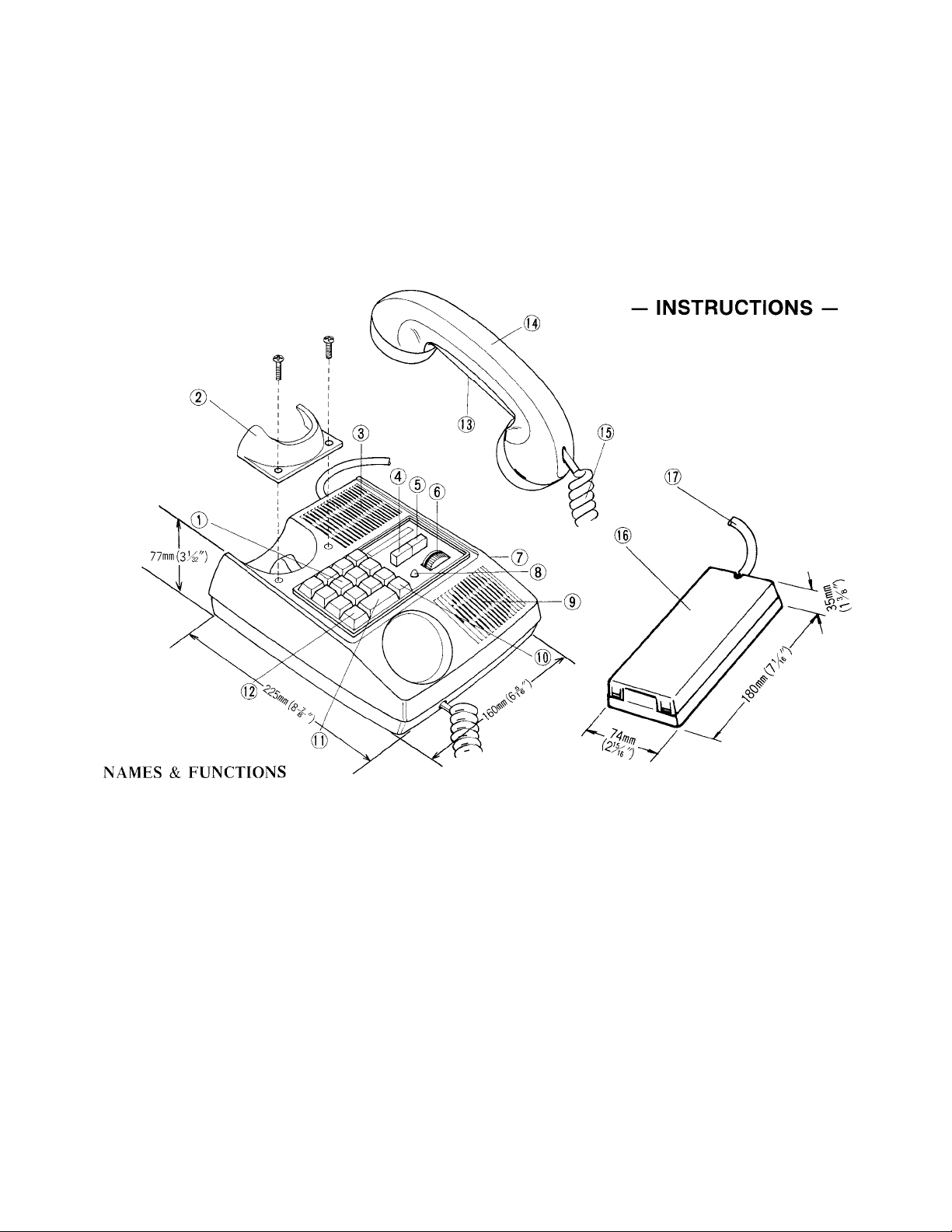
® Station selector buttons
(D Receiver cradle for wall
mounting
(D Loudspeaker
® Line privacy button
(D Station privacy button
® Volume control for
loudspeaker
SPECIFICATIONS:
* Power source:
* Current consumption:
* Calling:
* Loud speaking output:
* Paging:
* Wiring:
@ Volume control for privacy
call tone
(8) Call lamp
@ Loud-speaking microphone
® Expander button (A)
(only in KAH-24)
® Call button
Use straight conductor cable. Do not use twisted pairs.
DC 12 volt. Use PS-12S (or PS-12C in North America) AC adaptor.
250 mA maximum.
Push button station selection. A single stroke chime sounds when call button is depressed.
250 mW maximum during simultaneous conversation.
700 mW maximum when operating push-to-talk switch (P button)
Use paging adaptor PA-1 or PA-2 in conjunction with standard paging amplifier and speakers.
4 common wires plus one individual wire per station.
Example: 28 conductors for a 24 station system.
(T|) P button for paging announcement
and increasing loud speaker output
@ Directory card
il|) Handset
® Coil cord
@ Terminal box
® Terminal cord
Page 2

FEATURES
* Advanced integrated circuit provides superb fidelity and trouble free operation.
* Selective telephone or hands free function at the receiving station.
* Multi-channel system permits up to 12 separate conversations.
* A privacy switch is provided to prevent monitoring.
* A line privacy switch provides station lock out, preventing interruption by tone or voice.
* Separate privacy tone and volume controls.
* Conference call may include 4 stations.
* P button doubles volume at a receiving station to penetrate noise.
* Designed for desk or wall use.
OPTIONS
* Two call telephone type stations may be connected.
* Multi-channel paging either with or without talkback using accessories.
EQUIPMENT AVAILABLE FOR USE WITH YOUR KAH SPEAKER-PHONE
, 4^ KAH-12: 12 call speaker phone master
station.
■- KAH-24: 24 call speaker phone master
N.- > station.
KAH-2: 2 call telephone station.
PA-1: Block paging adaptor. Connects all
KAH phones to a paging system. May be
used in multiple for zone/block paging.
INSTALLATION
Do not attempt to install your intercom
procedure. Aiphone’s warranty is void if system
ACTUAL KAH TERMINAL LOCATIONS
KAH-12 KAH-24
y;2
" J
ACTUAL PA-1 TERMINAL LOCATIONS
"a g m ^
PA-2: Block paging with talkback.
Connects all KAH phones to a paging system
with talkback from speakers. May be used
in multiple for zone/paging with talkback.
SP-3: Paging speaker. Complete and ready
to install including round flush mounting
frame.
PS-12C: CSA & UL LISTED Power supply
(available only in North America).
PS-12S: Power supply (not available in
North America).
m
system until you have read and thoroughly understood the installation
is installed in a manner other than described in this manual.
for connecting relative stations.
for connecting relative stations.
for receiving a call.
for power supply.
___
© - ®
CaT)— <AJ2)
•
to be used if wire distance exceeds
200 m (600’) total or more than 13
stations are used in a system.
®, ©
for connecting AUX input of paging amplifier,
for connecting to background music source,
for power supply.
for connecting to a selector terminal of KAH stations.
+ - c
ACTUAL PA-2 TERMINAL LOCATIONS
®. ©
®, ©
d© Csp>
"" ©
for connecting AUX input of paging amplifier,
for connecting to background music source,
for connecting to paging speakers,
for power supply.
for connecting to a selector terminal of KAH stations,
for connecting to paging amplifier out-put.
Page 3
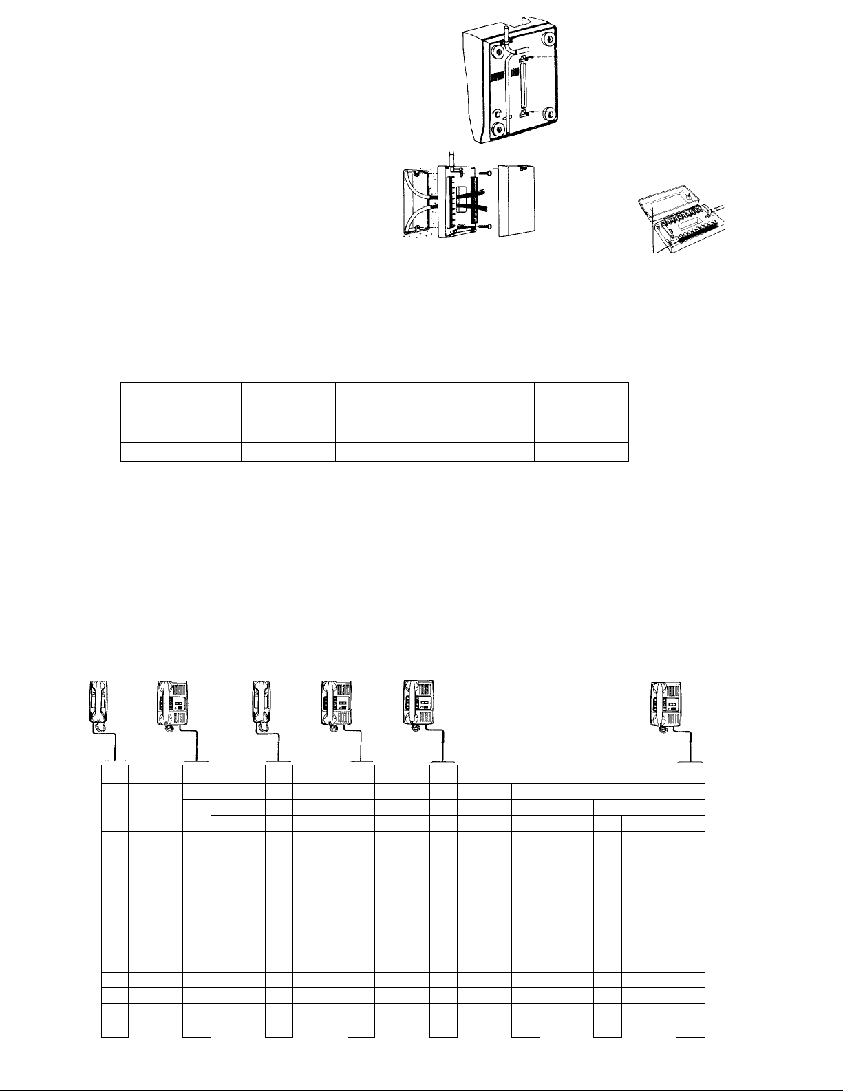
INSTALLATION FOR WALL MOUNTING
1) Attach the mounting bracket to wall or plaster ring.
2) Remove the rubber feet from base of station.
3) To attach the provided handset cradle, remove two
screws, place the cradle and reinsert the two screws.
IV-
8X5
:i::
1
INSTALLATION OF TERMINAL BOX
1) Remove screws and cover as shown.
2) Attach bottom case to wall or 1-gang box.
3) Replace cover after wiring.
Please refer to the labels
on the sides of terminal
box and back of the cover.
WIRING’ Use straight conductor cable. Do not use twisted pairs. TERMINAL IDENTIFICATIONS
Lay out your system in advance. Determine the exact location of each station. We recommend a full complement
of wire be installed, even though you may not initially be installing the maximum number of stations available to your
system. This way, should you decide to add a station later, you can avoid running additional cables to existing stations.
Connect wires to terminals 01 & 02 if wire distance exceeds 200m (600’) total or more than 13 stations are used in your
KAH system.
Refer to the chart below and select the proper wire gauge to meet your requirements.
AWG WIRE SIZE
DISTANCE 330' 550' 830'
DIAMETER OF WIRE
DISTANCE 120 m 200 m 300 m
24 AWG
0.5 mm
22 AWG
0.65 mm 0.8 mm
Referring to the diagram which illustrates your system, write your color code in the space privided. Begin your
installation with station #1. Note the position of the C terminal at each station. Be sure you wire each station correctly.
After installing the second station we recommend that the power supply be connected to the + and — terminals on
a phone and that a test be made for calling and talking between the stations. As each additional station is installed retest
between each station. Unplug power supply while making wiring connections.
20 AWG 18 AWG
1300'
1.0 mm
500 m
INTERMIXED KAH-12 SPEAKER PHONE AND KAH-2 TELEPHONE STATIONS
The telephone station KAH-2 can place a call to two other stations (or paging blocks) as selected upon installation,
and can receive a call from any speaker phone master station. For full information please refer to instruction sheet
packed with KAH-2.
KAH-2 KAH-12
1 0
20
C0
0i 0
0.^
-i-0
-0
c0
20
30
40
60
70
8 0
9 0
100
110
120
1 0
0, 0
oT^
_0
_
____
KAH-2
KAH-12
KAH-12
10
C0
701
70
c0
0, 0
_
-0 _0
6 6 60
VT^
8 0
90
100
110
120
20
0, 0
Oz0
TW
_
___
)
70^
7®
90
100
110
120
30
70"
02 0
+0
-0 _0
KAH- 2
1 0
c0
20
KAH- 2
1 1
1 2
( ^ 'i
T0
2_V)
c0
02 0 O2 0
V,
___
/
-0
KAH-12
7^
30
c0
7^
■y0
70
9 0
100
PS-12C or
PS-12S
110
POWER SUPPLY
120
4 0
6, 0
7^
_0
DC-12V
Page 4

^ s
Csl
Bis
см
го
CJ
CM
LO
CÛ
ü
CO
O
-
<
CM
Г0
<
<
<LO<
CD
<
r-<00
<
CD
<
O
<
<
CM
<
h'
c5
+
' j
<
О
H iO
И
В! И
■кИРПЬ;^"^
СЛ fes
о
н
<
Н [!|3 B!.
to NsjräaL
О
h- ^
<
I—
ш
о
н
<
t—
(Л
о
Н
<
hш
о
н -
<
н
(Л
Í
L_
S)
S'смS)
L
S)
ч
_
Í
s>l
смbго
b
см
го
го
b
bl
см
Ü
bl
р\
го
о
b
ь
b
b
b
LO
b
b
b
о
5)
bLOb
о
b
bLOb
■=^
b b
bЮbГ-b
LO
ь bib b
b
b
O
b
CD
b
CD
b
CD
Г--
r-
Г-
b
b
b
b
COb0)
CO
00
00bCD
00bCD
s>
b
O
S)
b
O
(J)
bl
b
O
0)
b
O
r '
b
b
O
b blbblblbb
b J
bi
s>
b
CM
<
S)
b
CM
<
S) '
b
CM
<
S» '
b
CM
<
S) -
b
CM
<
<<<<< <<<<<<<
b
b
CM
<
b
b
CM
<
b
b
CM
<
b
b
CM
<
b
b
CM
<
Г0
<b<
b
Г0
's!-
<
<
Г0
<b<
b
’=t
CO
<
<
b
CO
'Cj-
<
<
b
LO
<
b
LO
<
b
Ю
<
b
LO
<
b
LO
<
b
CD
<
b
CD
<
b
CD
<
b
CD
<
b
CD
<
bl
b
Г-
<
b
Г--
<
b
r-
<
b
Г-
<
b
r-
<
bl
b
b
b
O
CD
CO
<
<
<s<
b
b
b
O
CO
CD
<
<
< <
b
b
b
bl
b
00
<
b
CO
<
b
00
<
CD
<
b
CD
<
b
CD
<
O
<
O
<
O
<
blblb b
?
<
?
<
<
s»
b
CM
CD
<
b
b
CM
LO
<
s <
b
CM
<
b
b
CM
CO
<
S)'
b
CM
CM
<
b bl
r
O
r
c5sO
b
c5
b
ObO
S>
c5rO
b b b
r
O
s -
O
b
+
b'
+
b
+
b
+
b
+
b
1
s '
b Ì
1
b
1
b Ì
1
b 1
J
^а: —h-ш ^ —о: —20 üO-JODtr оосзш хшскш
Page 5

SPEAKER PHONE INTERCOM ALL MASTER SYSTEMS
ON
2T
'd
'¿
STATION
8
(
3 ^¿)
5 k3
6
"T^
"C^
10 1 0©
11 ^ 11 ©
12 © 12
^TT ©
[a^
7T©
A4 <(0
A5 ©'
A6 ©
A7 © A7 ©
A8 © A8 © A8 <0 A8 ©
A9 0 A 9 © A9 © A9 ©
A10 (^ )
All
A12 k3
8 (0
0, (¿1 0,© 0, © 0, ©
“oT©
~T^
“©
V. J
STATION
9
i-------------^
[“T©
3 ©
^T©
5 ©
7 ©
8 © 8 ©
C ©
A1 ©
A2 ©
A3 ©
A4 ^
aT©
A6 ©
A10 ©
All © A1 1©
A12 ©
O2© 0 2 © “oT© “oT©
T©
-©
L . J
STATION
10
^ \
1 ©
~F© 2©
3 © 3 ©
4 ©
5 ©
“T©
9 ©
“c©
11 ©
12 ©
A1 ©*
A2 ©
A3 ©
A4 ©
Ts^
A6 <(0
A7 © A 7 ©
A10 (^ AlO ©
A12 ©
10 ©
^T©
-©
k
_____
y
STATION
11
1 ©
4 4 ©
“T©
6 © 6 ©
7©
8 ©
9 ©
“Tc T©
“C©
12©
TT© A 1 ©
A2 ©
A3 ©
A4 ©*
■aT © A5 © A5 © A 5
A6 ©
STATION
12
^— — N
1 ©
2 ©
3©
5 © "T©
7©
8©
9 ©
10©
"TT © 11© T©
C©
A2 © A2 ©
A3©
A4 © A4 ©
A6 ©
TT©
A8 ©
A9 ©
A10 ©
All © '
A12 ©
All ©
A12 ©
TT© 12 ©
0, © “o7©
r
-1 - ©
-©
“T©
- ^
______
+ ©
-©
V J
>
■Q
STATION
13
f------------^ r
1 ©
2© 2 © 2 ©
"T© "T©
4 ©
6© T©
“T©
“sT ©
9 ©
10©
"TT ©
c©
A3 ©
A6 © A6 ©
|A7 ©
A8© A 8 © IA 8 ^ A 8 ©
A9 © A 9 < < 3» :a9 ©
A10 ©
aTT ^
A12 © aTT ©
A - ©
“or©
+© T©
-©
v
_____
PS-120
PS-12S
POWER SUPPLY
DC12V
^
STATION
STATION
14
-----------
^
1 ©
4© "T©
T©
7©
“8©
“9©
I0© “To ©
"TT © 1 2©
A1 ©
"c©
A3©
A4©
A7 ©
A10 ©
All©
A2 ©
"0©
"oT©
\
______
y
STATION
15
r
1 ©
“T© 3 ©
5©
~6©
7©
""T©
9 © 9 ©
11 ©
________1_______
A1 0
A2©
T©
A4 ©
A5 ©
A6 © A6 » 82
aT© A7 ©
'aio ©
[aiT © All ©
A12 ©
|A3 <0 A 4 ©
0, »82
O2 ©
+ ©
-©
16
f \
1 ©
2©
"T©
“T©
^"6 ©
/ ©
“8© i
10©
"iT©
12©
A1 © A
A2 ©
A3 ©
”c©
7^5 ©
A9 <8 2
AlO © AI
Ail© AI
“o7© C
“oT©
+ ©
-©
—
STA
r"
t
t
'
C
1
1
r
a:
a;
A^
(
Af
A'
Ai
A!
AI
A!
C
-
L
Page 6

ION STATION
18
STATION
19
STATION
20
STATION
21
STATION
22
STATION
23
STATION
24
STATION
25
Page 7

SPEAKER Ph
ON
STATION
8
STAT
CONNECTION OF PA-1 BLOCK PAGING ADAPTOR
1) Extend conductors from the phone network plus (+), minus (—) and an unused number terminal to
plus (+), minus (—) and C on the PA-1.
2) Using shielded cable, connect the background music source to terminals M and G on the PA-1.
3) Using shielded cable, connect terminals A and G on the PA-1 to the AUX (or PROGRAM) input of
the paging amplifier.
Each PA-1 provides a separate block and channel for paging.
AMPLIFIER REQUIREMENTS
* Input:
* Output:
AUX; more than lOK ohm, —10 dbm..
Less than 100 watt RMS with either 25, 70 or 100 volt line.
BACKGROUND MUSIC REQUIREMENTS
* Use audio output: RANGE; 100 mV — 1.2 V, 600 ohm — lOK ohm.
CONNECTION OF PA-2 BLOCK PAGING ADAPTOR WITH TALKBACK
1) Extend conductors from the phone network plus (+), minus (—) and an unused number terminal to
plus (+), minus (—) and C on the PA-2.
2) Using shielded cable, connect the background music source to terminals M and G on the PA-2.
3) Using shielded cable, connect terminals A and G on the PA-2 to the AUX (or PROGRAM) input of
the paging amplifier.
4) Connect the output of the amplifier 25, 70 or 100 volt line to terminals V, V on the PA-2.
5) Connect speakers to terminals SP on the PA-2.
Each PA-2 provides a separate block and channel for paging with talkback.
AMPLIFIER REQUIREMENTS
* Input:
* Output:
AUX; more than lOK ohm, —10 dbm.
Less than 100 watt RMS with either 70 or 100 volt line.
Less than 60 watt RMS with 25 volt line.
BACKGROUND MUSIC REQUIREMENTS
* Use audio output: RANGE; lOOmV—1.2V, 600 ohm—lOK ohm.
NOTE:
Due to line induction, TALKBACK paging noise control and volume adjustments become more difficult
as the line distance increases. Short wiring distances between the amplifier/PA-2 and the paging speakers
provide the best talkback paging and the best control. To assure the best possible talkback paging
system, we recommend a talkback speaker line consisting of shielded 2-conductor cable.
Page 8

INSTALLATION OF BLOCK PAGING ADAPTOR PA-1
This example illustrates connection if block paging is desired but without talkback. One phone must be deducted
from the system for each block. Each block requires one PA-1 and one paging amplifier. In this example selector button
#12 on each phone operates paging.
STATION
8
KAH-12
STATION
9
KAH-12
STATION
10
KAH-12
STATION STATION
11 12
KAH-12 KAH-12
INSTALLATION OF BLOCK PAGING ADAPTOR WITH TALKBACK PA-2
This example illustrates connection if block paging with talkback is desired. One phone must be deducted from the
system for each block. Each block requires one PA-2 and one paging amplifier. In this example selector button #12 on
each phone operates paging with talkback.
STATION
8
KAH-12
STATION
9
KAH-12
STATION
10
KAH-12 KAH-12
STATION
11
STATION
12
KAH-12
Page 9

COMBINATION OF STRAIGHT PAGING AND TALKBACK PAGING
DUE TO THE ADVANCED DESIGN OF THE PA-1 AND PA-2 BLOCK PAGING ADAPTORS, SEPARATE
CHANNELS MAY BE ESTABLISHED FOR PAGING OR PAGING WITH TALKBACK TO ANY NUMBER OF BLOCKS.
1) One potential phone must be deducted for each PA-1
or PA-2 installed.
2) One amplifier must be used with each PA-1 or PA-2.
3) Only one background music source, if used, is required
for entire system.
This example shows one area of talkback paging (block #1)
and two areas of paging without talkback (block #2 and
#3).
Selector button #10 on each phone operates block #1,
selector button #11 operates block #2, and selector
button #12 operates block #3.
-TO PHONES
0
c
at
TALKBACK
SPEAKER
00'
Э
MGA
+
э
SP
VэV
G
BLOCK 1
PAGING
PA-2
This is a multi-channel paging system meaning more than
one paging operation may take place at the same time.
For full information please refer to instruction sheet
packed with the PA-1 or PA-2.
T
0
P
H
o.
N
E ■
N
E .
T
W ■
0
R
K ■
STATION STATION
8
KAH-12
x
10
3 0
4 0"
5 0
T0^
8 0 8 0 ■ 70
9 0
6 0
ToW
W
120 120
Oe® 02 0
-0
_
______
T0"
‘20‘
-3^0'
6 0
9 '¿2
To^"
110
0, 0
-0
s
______
—^
p©
30
7©
6*0
■y©'
T©
8 0
100
TT©
120
~P0
_0
STATION
10
KAH-12“
y©
20
"t®!
40
5 0
6 0
T©
c 0 90
9 0
100
W
120
0, 0
y©
-0
■ 70
"c®
y©l
s
10
8'^
50
70
100
120
020
-0
____
01^0 0
IN
AMP
BLOCK 2
PAGING
SPEAKER
AMP
^ 0
IN
\W
+
c
0
G
0 0
A G
PA-1
BLOCK 3
PAGING
SPEAKER
AMP
0
0(
IN
-f
A G
0
P
__
Y PA-1
OD
BACKGROUND
MUSIC SOURCE
PS-12C or
PS-12S
^
POWER SUPPLY
Page 10

OPERATION
Calling;
Lift the handset and depress the selector button desired to communicate with, then momentarily depress the C button.
This will sound a single stroke chime which indicates that the connection has been established.
1) If you hear a repeated tone, it means that the called station is switched for the privacy position. Wait for an answer
or call later.
2) If you hear a continuous tone, it means that the called station is in the Line privacy position. Please call later.
3) If you hear no tone, it means that the called station is busy. Please call later.
4) If you hear a conversation, it means that the called station is in open voice communication.
* If the noise level at the called station is high, you may increase the output by using the P button, press to talk release
to listen.
Receiving;
When your station is in non-privacy position, an incoming call is announced by single stroke chime and a call lamp.
A reply can be made hands free using loudspeaking microphone or privately by using the handset.
When your station is switched for the privacy, an incoming call is announced by a repeated tone and a call lamp.
A reply can be made by using the handset or by unlocking the privacy button and conversing handsfree.
When your station is switched for the Line privacy, an incoming call is announced only by the call lamp. The calling
station understands that you are not in a position to reply and will cancel his call.
Adjusting privacy tone volume;
A volume control is provided on the rear of the unit to adjust the privacy tone volume. Adjust as desired.
TELEPHONE STATION KAH-2 OPERATION
The telephone station KAH-2 is equipped with 2 station selector buttons, a call button and a P button. It can place
calls to two speaker phone master stations as selected upon installation. The KAH-2 can receive a call from any speaker
phone station. Operation of the KAH-2 is the same as the speaker phone stations but reply can be made only by using the
handset.
PAGING OPERATION
If appropriate equipment is installed, select the zone you wish to page and momentarily depress the C button to
establish the channel. Use the P button for press to talk (and if PA-2 is used, release to listen). Background music will
be automatically cut off.
CLEANING YOUR INTERCOM STATIONS
* Your Aiphone intercom stations may be cleaned with a soft cloth dampened with household cleanser, such as Mr.
Clean or Fantastik.
We at AIPHONE are proud of our products. Our designers and engineers strive to bring you the finest in commu
nication equipment. Each item has been carefully tested and inspected before leaving our factory. Properly installed and
used, your Aiphone intercom system should give years of trouble-free service.
We are pleased to offer the following warranty:
WARRANTY
Aiphone warrants its products to be free from defects of material and workmanship under normal
use and service for a period of one year after delivery to the ultimate user and will repair free of
charge or replace at no charge, should it become defective upon which examination shall disclose
to be defective and under warranty. Aiphone reserves unto itself the sole right to make the final
decision whether there is a defect in materials and/or workmanship; and whether or not the prod
uct is within the warranty.
This warranty shall not apply to any Aiphone product which has been subject to misuse, neglect,
accident, or to use in violation of instructions furnished, nor extended to units which have been
repaired or altered outside of the factory.
This warranty does not cover batteries or damage caused by batteries used in connection with the
product.
This warranty covers bench repairs only, and any repairs must be made at the shop or place des
ignated in writing by Aiphone. Aiphone will not be responsible for any costs incurred involving on
site service calls.
Aiphone Co., Ltd., Nagoya, Japan
Aiphone Corporation, Beiievue, Washington
KAH-l-0182 ©
Smm
MjM
ALL OVER THE WORLD
■iii
AIPHONE
PRINTED IN JAPAN
 Loading...