

Page 1
JK-DVF-XP
Video Door Station with Standalone Prox Reader
- INSTRUCTIONS -
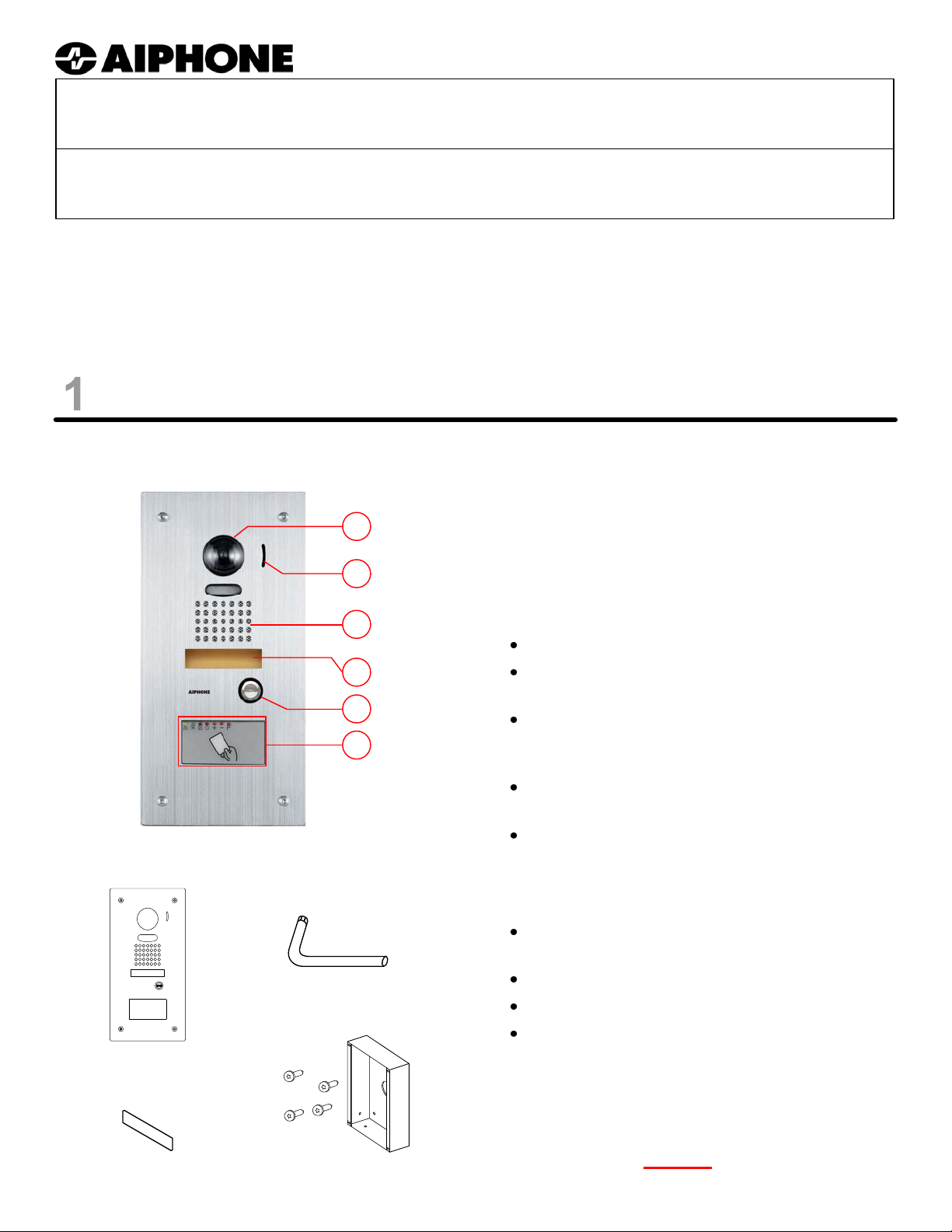
The JK-DVF-XP is a color audio-video door station for Aiphone’s JK-series, containing a standalone proximity card
reader with embedded host controller. Capable of storing up to 5,000 sets of credentials (cards) and operating
completely independent of an external host controller or PC, the JK-DVF-XP is ideal for all installations wh ere reliable,
inexpensive and easy-to-manage access control is desired.
Note: Programming of the JK-DVF-XP requires Aiphone’s XP-KIT Programming Starter Kit for -XP series standalone
proximity card readers.
NAMES & FEATURES
JK-DVF-XP
PACKAGE CONTENTS:
NAMES & FUNCTIONS:
1. Camera 4. Speaker
1
2. Microphone 5. Call button
3. Name placard 6. Standalone Prox
2
3
FEATURES:
Reader / Controller
Up to 5,000 credential storage (cards)
4
Standalone configuration without central ‘Host’
or personal computer
5
6
Night Lock function with contact output for
controlling after hours access and alarm
system mode
Forced Entry alarm output for triggering
external sounder or alarm system
Optional handheld Remote Programmer for
advanced functionality
OPTIONAL ACCESSORIES:
Vandal-resistant Door Station
JK-DVF-XP
Blank name
placard
Security Driver
Semi-flush backbox &
tamper-resistant bolts
SBX-DVF-P – Surface-mount stainless steel
backbox
XC4/9 – Blank User Card (Qty. 1)
XRP3 – Handheld Remote Programmer
XP-KIT – Programming Starter Kit,
contains:
XRP3 – Qty (1)
XC4/9 – Qty (10)
XMMC3/9 – Qty (1)
(Note: XP-KIT is required
for programming of
the JK-DVF-XP.)
Pg. 1
Page 2
MOUNTING & INSTALLATION
Installation Location:
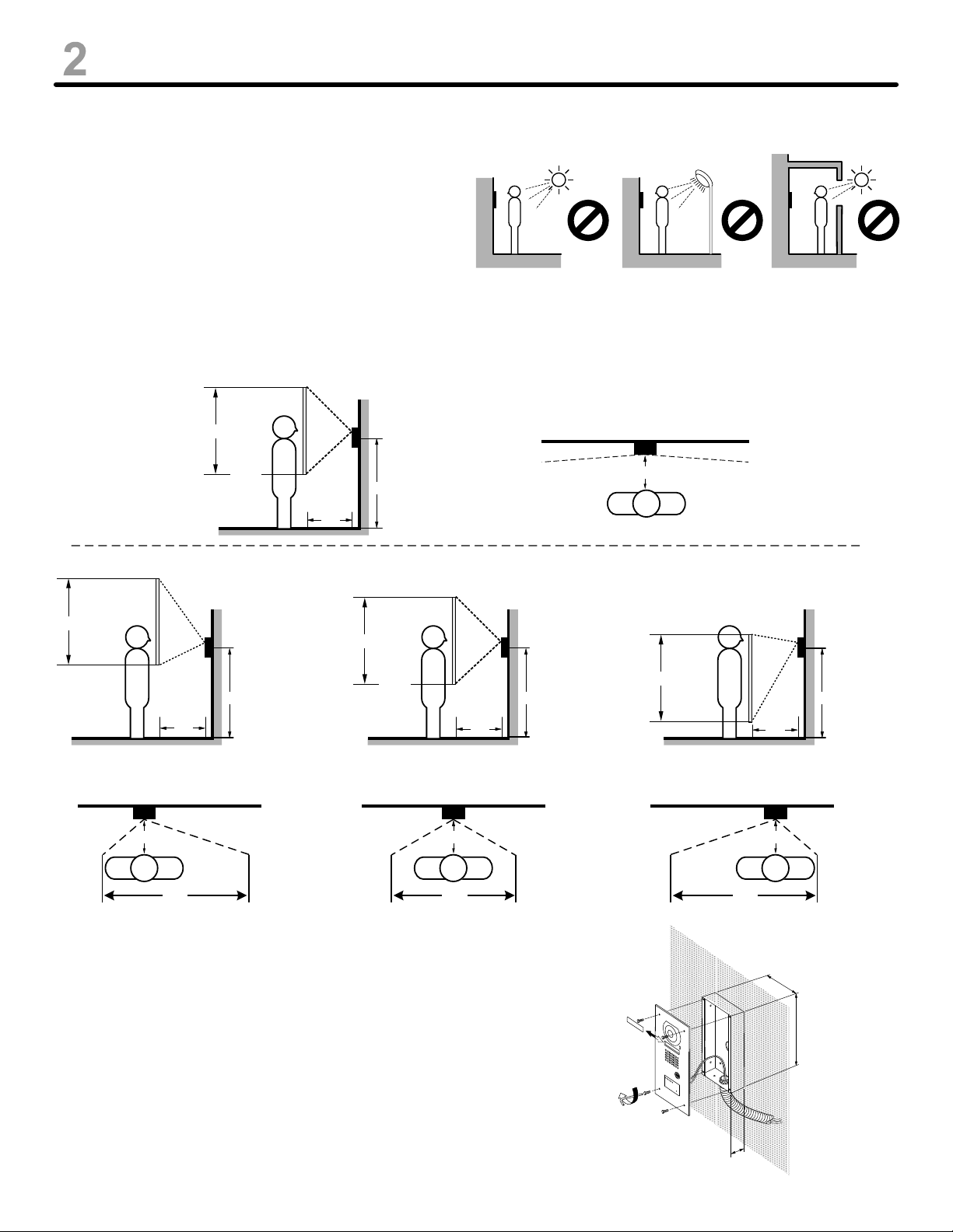
Care should be taken when choosing the best
location for mounting the JK-DVF-XP. Do not
install the video door station in any areas
subject to direct sunlight or other strong direct
lighting conditions; installation in such
locations may cause reduced visibility and/or
video quality while viewing from the master
station.
Mounting Height & Viewing Angle: Wide and Zoom Picture
Wide Up/Down Wide Left/Right
6'7"
170° angle of view
3'5"
JK-DVF-XP
JK-DVF-XP
2'10"
20"
5'4"
2'10"
2'6"
7'5"
4'7"
Zoom Up
20"
3'2"
JK-DVF-XP
5'
20"
5'
Zoom Center Zoom Down
6'1"
2'4"
3'9"
20"
JK-DVF-XP
5'
Zoom Left Zoom Center Zoom Right
JK-DVF-XP
20"
4'7" 3' 4'7"
JK-DVF-XP
20"
JK-DVF-XP
JK-DVF-XP
5'
20"
20"
Physical Mounting Instructions:
1. JK-DVF-XP – provide wall surface opening for rough-in
backbox (supplied), using dimensions shown (Fig. 1).
Note: if surface mount is required, use the Aiphone
SBX-DVF-P (sold separately) .
2. Connect the 2 conductor wire to
terminals A1 and A2 on back of unit.
3. JK-DVF-XP – Secure the door station to
the backbox using the included security
screws / driver (Fig. 1).
1-25/32"
Figure 1
4-1/2"
8-7/16"
Pg. 2
Page 3
WIRING
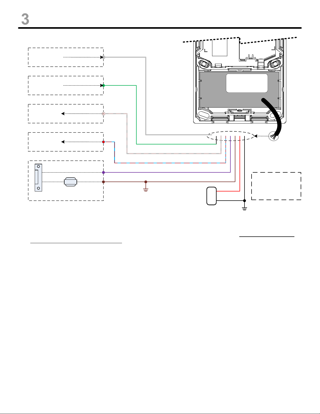
Forced Entry
Sensor Input
Request-Exit
(Egress) Input
Forced Entry
Trigger Out
Night Lock
Trigger Out
Strike
DC Power
(See Note 4)
(See Note 2)
(See Note 4)
(See Note 3)
(See Note 1)
Grey
Green
Grey / Pink
Red / Blue
Violet (Lock)
Brown (Ground)
+
-
Red
Black
White: Not Used
Yellow: Not Used
Pink: Not Used
Blue: Not Used
12V DC
Power Supply
NOTES:
1. The ‘Lock’ output (Violet wire) is a normally-open solid-state contact rated at 30VDC / 1A. Only DC-powered locks
can be connected directly to the reader. Locks requiring AC power, higher contact rating, or Normally-Closed
functionality should use an external 12VDC relay (Aiphone RY-18L or equivalent). Release duration is determined
by the reader’s programming configuration (see the -XP Series Programming & Operation Manual).
2. The ‘Request-Exit’ input is used when triggering the reader’s internal contact output from an external contact source
is desired (motion detector, egress button, intercom relay output, etc.). An input closure should be connected
across the Green wire and Ground (Brown wire). Unlock events triggered by this input are also subject to the
reader’s release duration (see the -XP Series Programming & Operation Manual).
3. When the Night Lock mode is active, a trigger will be provided across the ‘Night Lock Trigger Output’ (Red / Blue
wire) and Ground (Brown wire). This can be used to integrate with external alarm systems for improved
functionality.
4. The ‘Forced Entry Sensor Input’ (Grey wire) is designed to be connected to Ground (brown wire) in series with a
magnetic door sensor (or equivalent normally-closed device) to allow the system to determine when the door has
been either forced, or left open after an unlock event. When this sensor input active, an output trigger will be
provided across the ‘Forced Entry Trigger Out’ (Grey / Pink wire) and Ground (Brown wire), for connection to an
alarm system event input, sounder, or other desired device.
5. All device outputs (with the exception of the Violet ‘Lock’ output) provide a low current trigger output, and should not
be used to drive anything greater than another device’s trigger input without an appropriate relay. All device inputs
require only a contact closure across the respective wire and Ground (Brown wire).
6. The White, Yellow, Pink, and Blue wires are not used and should be trimmed to avoid possible shorting and system
malfunction.
Note: Only information pertaining to the wiring of the -XP series card reader is shown in this manual. For programming
information, consult the -XP Series Programming & Operation Manual (included in the XP-KIT Programming Starter
Kit). For JK series intercom configuration / connection information, consult the JK series Installation and
Operation Manual.
Pg. 3
Page 4
SPECIFICATIONS
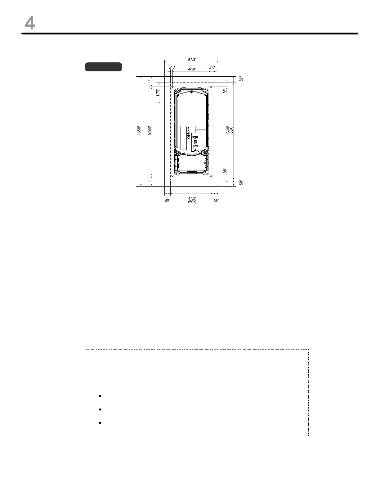
DIMENSIONS:
PROGRAMMING:
JK-DVF-XP
See programming instructions included with the required XP-KIT Programming Starter Kit (sold separately).
Note: Do not attempt to program or use the JK-DVF-XP door station without first reading the
initialization instructions included with the XP-KIT Programming Starter Kit!
SPECIFICATIONS:
CARD READER:
Power Source: 12V DC
Current Requirements: 40mA (Avg)
Terminations: Color-coded pre-wired pigtail
Operating Temperature: -10°~60°C / 14°~140°F
Operating Humidity: 0-95% relative humidity
non-condensing
FCC WARNING:
This device complies with Part 15 of the FCC rules.
Operation is subject to the following two conditions:
(1) This device may not cause harmful interference.
(2) This device must accept any interference that may cause undesired operation.
For proper regulatory compliance, the drain wire should be disconnected at the
power supply end of the cable.
Changes or modifications not expressly approved by the party responsible for
compliance could void the user’s authority to operate the equipment.
The Reader is intended to be powered from a limited power source output of a
previously certified power supply.
DOOR STATION:
Power Source: JK-1MED / JK-1MD master
Camera unit: CMOS Camera
Scanning line: 525 lines
Min. illumination: 5 Lux at 1' or less
Terminations: Screw terminals
Operating Temperature: -10°~60°C / 14°~140°F
Wiring Distance: 330ft w/ 87180250C wire
Aiphone Communication Systems
1700 130th Ave. N.E.
Bellevue, WA 98005
(425) 455-0510
FAX (425) 455-0071
TOLL FREE TECHNICAL SUPPORT:
(800) 692-0200
E-MAIL: [email protected]
JK-DVF-XP Instr.
Pg. 4
0110JD
 Loading...