

Aiphone IX-DVF-4 Installation Manual

IX-DVF-4
IX Series Video Door Station with 4 Call Buttons
-INSTALLATION AND PROGRAMMING GUIDE-
The IX-DVF-4 is an IX Series video door station with 4 call buttons for selective calling to IX-MV7
or IX-MV master stations. The IX-DVF-4 will connect to a network switch, and the call buttons are
connected to the rst 4 contact inputs on the station. These inputs will be programmed to selectively
call dierent master stations, or groups of master stations.
IX-DVF-4
PACKAGE CONTENTS:
NAMES & FUNCTIONS:
1. Camera
1
2
2. Microphone
3. White LED for night viewing
4. Speaker
3
4
5. Call buttons with integrated name placard
FEATURES:
• IP video door station
• 4 call buttons for selective calling to master stations
• 4 name placards
5
• Stainless steel faceplate with tamper resistant screws
INSTALLATION:
IX-DVF-4
4 Call Button
Door Station
tamper resistant screws
Security Driver
Blank name
Flush backbox &
placard x4
• For ush mounting, cut a hole in the wall and use the
supplied back box.
Box dimensions are: 10-½" H x 5-13⁄16" W x 2-⅜" D
• For surface mounting, use the SBX-IDVFRA surface
mount box. This box can mount to a standard 1 gang
box or to any at surface.
Note:
When installing the IX-DVF-4 in the supplied back box, the call
button assembly may come loose. Push call button assembly
back in to position as necessary.
Pg. 1
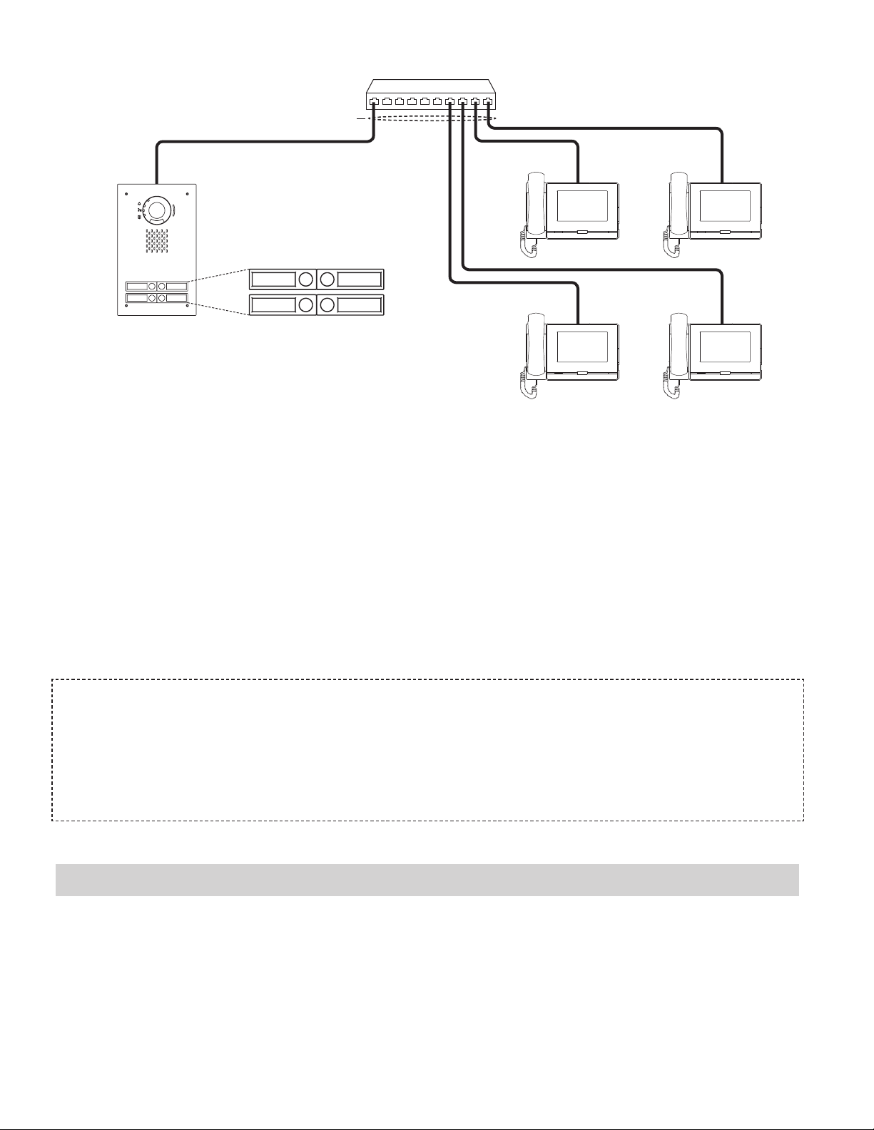
WIRING DIAGRAM:
IX-D VF- 4
11-11/ 16 "
10 -1/ 2 "
11-11/16 "
10 -1/ 2 "
PoE Switch
Cat-5e / Cat-6
Button Pattern
1 2
3 4
IX-DVF-4
SPECIFICATIONS:
Camera unit: 1/3" color CMOS 1.2 megapixal
Min. illumination: 5 Lux
Terminations: RJ45
Operating Temp: -40° ~ 140°F / -40° ~ 60°C
Wiring Distance: 328' with CAT-5e/6 cable to switch
Dimensions: 11-¾" H x 7" W
w/SBX-IDVFRA: 11-11⁄16" H x 7" W x 3-5⁄16" D (top), 2-5⁄16" D (bottom)
IX-MV7
IX-MV7
IX-MV7 IX-MV7
FCC WARNING:
This device complies with Part 15 of the FCC rules.
Operation is subject to the following two conditions:
(1) This device may not cause harmful interference.
(2) This device must accept any interference that may cause undesired operation.
• For proper regulatory compliance, the drain wire should be disconnected at the power supply end of the cable.
• Changes or modications not expressly approved by the party responsible for compliance could void the user’s authority to operate the
equipment.
Programming
This programming guide will cover how to program an IX-DVF-4 door station and four IX-MV7 master
stations. The call buttons on the IX-DVF-4 are wired to the rst 4 contact inputs on the station for placing
selective calls. The door station and the associated IX-MV7 master stations will need to be programmed
using IX Support Tool.
Pg. 2
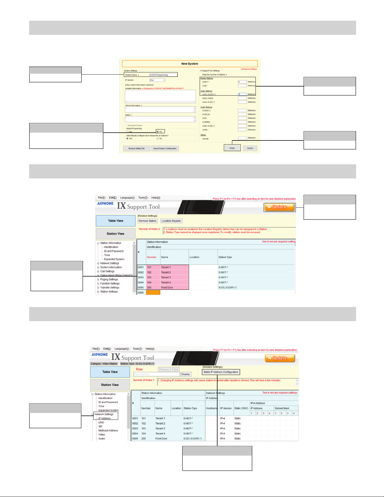
Support Tool: Create New System - Step 1
Open the IX Support Tool and click File, Create New System.
Step 1A
Enter a System Name
Step 1B
Select the No radio button under
Wizard Programming
Support Tool: Station Identication - Step 2
Support Tool will open in Table View to Station Information, Identication.
Step 1C
Enter station quantities
Step 1D
Click Finish
Step 2B
Click Update to save
changes.
Step 2A
Enter a unique Number
and Name for each
station.
Support Tool: IP Address - Step 3 (Table View)
IP Addresses can be entered manually for each station or can be assigned in a batch. This guide will show
how to assign via batch conguration.
Step 3A
Under Network Settings,
Click IP Address
Step 3B
Click Batch IP Address
Conguration
Pg. 3
 Loading...