

Page 1
GFW-VBC.E MANUAL TH 1002
®AIPHONE
4-WIRE BUS VIDEO APARTMENT INTERCOM SYSTEM
G F W“V B C '^ideo expander control unit
INSTALLATION MANUAL
/i\ GFW-VBC is compatible with GF-VBC/A unit only (not GF-VBC).
FEATURES
The GFW-VBC is designed to enlarge video capacity of GF apartment system in
combination with GF-VBC/A and one more GFW-VBC;
Purpose
1. To increase total monitor stations
2. To maximize wiring distance
3. To increase Video trunk lines
Note; Up to two GFW-VBC's (in series) can be installed per system.
Total 150 units GF-IMD(K) expandable to 151~250 units
Max. 150m. Doubled to 300m with one GFW-VBC, tripled
to 450m with two GFW-VBC's
One video trunk line can be divided into 6 trunk lines,
totaling max. 216 video trunk lines.
Standard & expanded capacity
PRECAUTIONS 0 General Prohibitions Prohibitions to subject the unit to water
/^WARNING (Negligence could result in death or serious injury to people)
1. This device is electrical. Wiring must be done by qualified personnel.
2. Do not dismantle or alter the unit. Fire or electric shock could result/
3. Do not connect any power source other than specified to terminals -h0^n the unit. Fire or electric /0^
shock could result. \0y
4. Keep the unit away from water or any other liquid. Fire or electric shock could result.
5. Make sure wires are connected properly before plugging the power supply into an electrical outlet.
6. For DC powered systems, use Aiphone power supply model specified with system. If non-specified
product is used, fire or malfunction could result.
/^CAUTION (Negligence could result in injury to people or damage to property)
1. Do not install or make any wire terminations while power supply is turned on. Unit trouble could result,
2. Mount the unit on wall in-a convenient location, but not where it could be bumped or jarred.
Injury could result. vO/
3. Do not install the unit in any of the following locations, as it may cause the system to malfunction;
- High or extreme cold temperature area:
under direct sunlight, near equipment that varies in temperature, in front of air-conditioner,
inside a refrigerated area, etc.
- Places subject to moisture or humidity extremes, such as bathroom, cellar, greenhouse, etc.
- Places subject to environmental conditions, such as dust, oil, chemicals, salt, etc.
- Places subject to constant vibration or impact.
- Places subject to steam or smoke, such as near heating appliances, cooking surface, etc.
GFW-VBC
Package contents
' GFW-VBC
' INSTALLATION MANUAL
Prohibitions to dismantle the unit
0
0
GENERAL PRECAUTIONS
1. The equipment, except the entrance station, is designed for indoor use only. Do not install them outdoors.
2. The system is not operable during a power failure.
3. Keep all wiring at least 30cm, 1' away from AC100 ~ 240V wiring, fluorescent lighting, or dimmer switches.
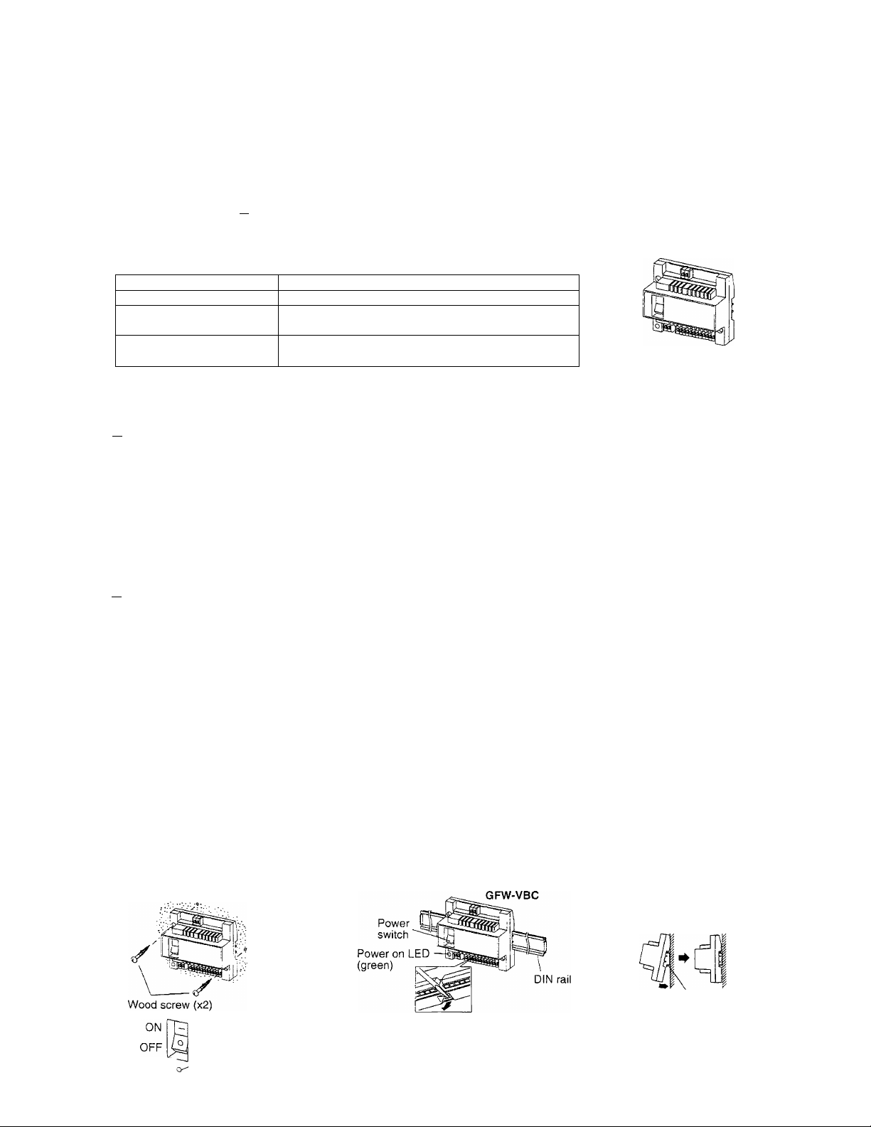
MOUNTING
Power
switch
^ Green LED lit
Othenwise, cross AC wiring at a 90° angle.
GFW-VBC
Wall
When green LED is not lit, turn off the Power switch on GFW-VBC, and check on wiring and fuse
inside the power supply.
Mounting rail for GFW-VBC;
W-D1N11 available
from Aiphone
Mounting rail
- 1 -
Page 2
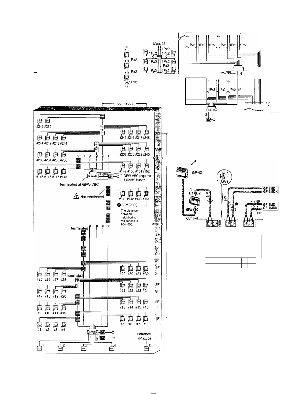
SYSTEM CONFIGURATION
[T] Example to maximize wiring distance
8 residences per floor, 32 floors; max. 250 residences
• Distance calculation: From GF-VBC/A or
GFW-VBC to the farthest monitor station;
Max. 150m w/0 0.8mm (500' w/20AWG)
per video trunk line.
Q (D 51m + 80m = 131m
170'+ 260'= 430'
0 + 0 39m + 80m = 119m
128'+ 260'= 388'
A CAUTION
Do not mix both wiring
methods: monitor-to monitor
and homerun to GF-4Z's for
any residential trunk line.
Monitor-toMonitor wiring
Max. 25
ilPx2
0
Homerun wiring
1Px2
Expanded Bus lines
Standard Bus lines
_1Px2
_1Px2
IGFW-VBCI-
I
0
39m(128')
o
51m(170')
The height of
each floor is
3m(10').
Distribution 2T
point for AUDIO [M-Q:
When GFW-VBC further extends trunk line;
On the GF-4Z, the GFW-VBC is connected
to, put SW1 to B position (not terminated).
A
LINE OUT OUT(3) OUT(4)
OUT(2)
Lj
JLII
R1IR2li
0
n
LINE IN OUT(1)
1/,
0 GF-4Z
JIFinnrL
IB1IB2IR1IR2I B1|B2
o
Eb6i
Audio wiring is not shown.
(*1): Install an add-on power supply when 2nd GF-1MD is installed in each apartment.
2 -
irrrr
O-i
z«
LINE V
OUT B1|B2
LINE
IN B1?|B2
r* *1: GFW-VBC, GF-VBC/A |^: Power Supply
•"[1 :GF-1MD(GF-1MDK) Q:GF-VA
B :GF-4Z
GF-4Z
• i?CL
’1Z
/NR
NP
GF-1MD
GF-1MDK
_1
Page 3

2] Example to increase video trunk lines
4 residences per floor, 12 floors (total 48 residences), 5 blocks; total 240 residences
• Distance calculation : From GF-VBC/A or GFW-VBC to the farthest
apartment stations; Max. 150m w/00.8mm (500' w/20AWG) per video
trunk line.
O + © + ® 80rn + 33m + 30m = 143m
260' + 108' + 100' = 468'
r* "l: GFW-VBC, GF-VBC/A
OQ :GF-1MD(GF-1MDK)
a*
Q :GF-4Z
A\ CAUTION
Do not mix both wiring methods: monitor-to-monitor and
homerun to GF-4Z's for any residential trunk line.
; Power Supply
|S):GF-VA
80m(260')
Q
80m(260')
Distribution 2T
point for AUDIO ra-Qi
GF-BCl
30m(100')
rr, -o'iSTi'H? 111f. /1
Audio wiring is not shown.
(*1): Install an add-on power supply when 2nd GF-1MD is installed in each apartment.
-3-
Jilt .r.aaiMEa
Page 4

WIRING
For entire GF system wiring, refer to GF system's Installation manual.
• Power source: DC 24V, supplied by a power supply
• Current consumption: 0.9A.
•Wiring:
•Type of Cable:
•Wiring distance:
Diameter of wires
GFW-VBC to farthest GF-1MD
1 per resid. line 100m
GFW-VBC to GF-VBC/A
GFW-VBC to farthest GF-1MD
2 per resid. line
GFW-VBC to GF-VBC/A
GFW-VBC to power supply
This equipment has been tested and found to comply with the limits for a Class B digital device, pursuant to Part 15 of the FCC
Rules. These limits are designed to provide reasonable protection against harmful interference in a residential installation. This
equipment generates, uses, and can radiate radio frequency energy and, if not installed and used in accordance with the
instructions, may cause harmful interference to radio communications. However, there is no guarantee that interference will not
occur in a particular installation. If this equipment does cause harmful inteference to radio or television reception, which can be
determined by turning the equipment off and on, the user is encouraged to try to correct the interference by one or more of the
following measures:
• Reorient or relocate the receiving antenna. • Connect the equipment into an outlet on a circuit different from that to which the
receiver is connected. • Increase the separation between the equipment and receiver. • Consult the dealer or an experienced
radio/TV technician for help.
♦f*
♦j*
^ Aiphone warrants its products to be free from defects of material and workmanship under normal use and service for a period
of one year after delivery to the ultimate user and will repair free of charge or replace at no charge, should it become defective
^ upon which examination shall disclose to be defective and under warranty. Aiphone reserves unto itself the sole right to make
the final decision whether there is a defect in materials and/or workmanship: and whether or not the product is within the
X
♦5* warranty.
PS-241 OLC, PS-241 OLD or PS-24ME/A.
2 X 2-wire cables common.
2-conductor cable solid copper & non-braided,
polyethylene insulation, 0.65mm dia. ~ 1.0mm dia.
(22AWG ~ 18AWG).
0.65inm
0.8mm1.0mm22AWG20AWG
—
150m
50m
100m 150m 165'
—
5m
— —
330' 500'
330'
16'
18AWG
—
500'
—
WARRANTY
Capacity:
Standard system
•Video control unit
• Total monitor station
Dimensions & weight:
108.5mm (H) x 122.5mm (W) x 61 mm (D) 260g approx.
4-1/4"(H) X 4-13/16"(W) X 2-3/8"(D) 0.57 lbs. approx.
1 X GF-VBC/A
150XGF-1MD
(orGF-lMDK)
Expanded system
1 X GF-VBC/A
2 X GFW-VBC
250 X GF-1 MD
(orGF-lMDK)
X This warranty shall not apply to any Aiphone product which has been subject to misuse, neglect, accident, or to use in violation
X
of instructions furnished, nor extended to units which have been repaired or altered outside of the factory.
^ This warranty does not cover batteries or damage caused by batteries used in connection with the unit.
^This warranty covers bench repairs only, and any repairs must be made at the shop or place designated in writing by Aiphone.
• Aiphone will not be responsible for any costs incurred involving on site service calls.
AIPHONE CO., LTD., NAGOYA, JAPAN
AIPHONE CORPORATION, BELLEVUE, WA, USA
AIPHONE EUROPE N.V., ANTWERP, BELGIUM
Oaiphone
Providing Peace of Mind
http://www.aiphone.com/
Printed in Thaiiand (E)
♦i*
-J*
-i*
•i*
-{♦
-j*
-i-
-4-
 Loading...