

Page 1
1105
Open Voice Tenant Station for the GF System
- INSTRUCTIONS -
The GFO-1DL and GFO-1DLF are open voice tenant stations for the GF system. The unit features door answering and
door release with up to five entrance stations, Concierge call, and the connection of an optional panic call station (GFKPS). A separate standard doorbell can be added to ring the unit with a unique tone. The unit includes TALK, DOOR
RELEASE, and CONCIERGE CALL buttons. Each GFO-1DL counts as 2.5 handset stations on a standard GF system,
therefore the maximum capacity of the system is 100 stations (see specifications).
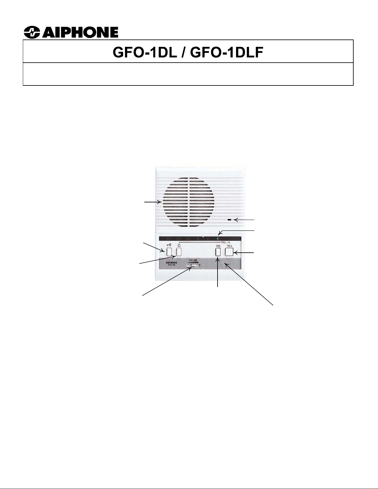
NAMES & FUNCTIONS:
Speaker
Microphone
LED: Green during
KEY SYMBOL: Press
to release the door
BELL SYMBOL: Press
TALK first, then BELL button
to call the Concierge/
Security Guard (if
applicable)
VOLUME: Controls
incoming volume
END: Press to end the
call (with the entrance
panel or concierge).
LED flashes red when call tone is OFF.
communication
TALK: Press to
answer call, release
to listen
CALL TONE VOLUME:
3-position switch underneath faceplate
to adjust call tone to OFF, MID, HIGH.
COMPATIBILITY:
1. The GFO-1DL can be used in any GF system as an audio-only open voice room station.
(No video if used in a video system.)
- GF Audio entry with buttons
- GF Audio entry with digital entrance panel
- GF Video entry with buttons
- GF Video entry with digital entrance panel
2. Station capacity of the GF system changes when using open voice tenant stations. Each GFO-1DL
occupies the capacity of 2.5 handset or monitor stations, thus lowering the overall number of
tenant stations allowed in a system.
Pg. 1
Page 2
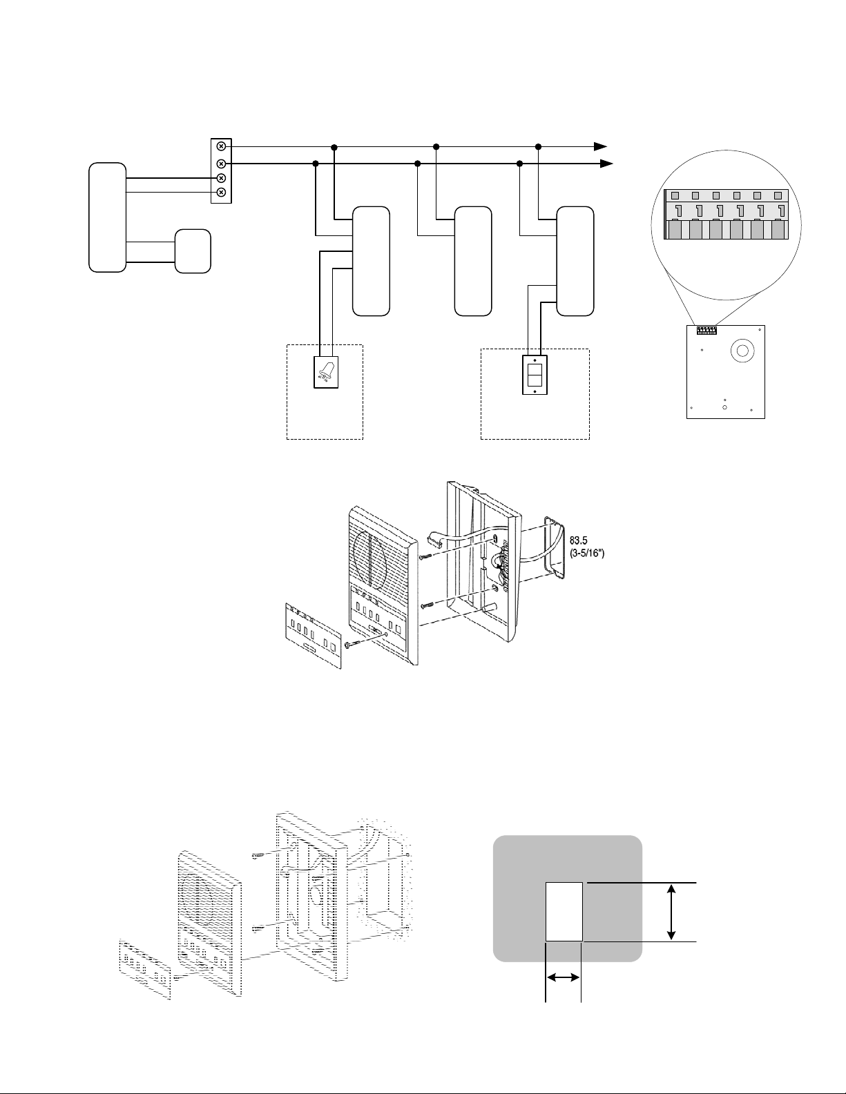
WIRING DIAGRAM:
(Entrance panel(s) not shown)
Wire junction
point**
GF-BC
R1
R2
+
-
**Distribution point can be
any type of terminal strip,
punch down block, or suitable
wire connection point for
multiple bus lines of stations.
Up to 20 GFO-1DL's can be
run on each bus line.
Red
+
Blk
-
PS-2410LC
Common
Bus Line
GFO-1DL
Doorbell
button*
GFO-1DL
R1
R2
C
CE
K
KE
*Optional Features
R1
R2
C
CE
K
KE
GFK-PS Panic
Call Switch*
GFO-1DL
R1
R2
C
CE
K
KE
TERMINAL LOCATIONS:
KE K CE C R2 R1
MOUNTING:
Surface Mount Installation:
Operation plate (peel off
protective film). Bend at one
corner and remove, then
reattach after installation.
NOTE:
The images above and below are for illustration purposes only.
The GFO-1DL(F) wire terminals are directly on the unit, not in the chassis itself.
Flush Mount Installation:
Attach chassis to
wall surface, or
set on a desktop.
Loosen screw
(don’t remove)
CUT OUT HOLE
DIMENSIONS
WALL
Cut appropriate sized
hole in wall, or install
BBX-1E during new
construction.
6-1/8" (155 mm)
3-3/4” (96 mm)
Pg. 2
Page 3

PROGRAMMING & OPERATION:
PROGRAMMING THE SYSTEM (INDIVIDUAL BUTTON PANEL):
1. Remove faceplate of GF entrance panel.
2. Lift rubber cap located on the upper right side of the GF-DA/B speaker module.
3. Using a long slender tool, momentarily press the programming button through the hole inside the GF-DA/B.
4. The In-Use LED will blink for approximately 15 seconds, then will become steadily lit.
5. With In-USE LED steadily lit, press the TALK button momentarily on the GFO-1DL you wish to program. (Only
one station can be programmed at a time.) Communication will be present (push-to-talk, release-to-listen at unit).
6. Momentarily press the call button in the GF-SW that is designated to call that tenant station. A single beep will be heard.
7. Press END button on GFO-1DL. (This is like hanging up the handset on a standard GF-1DK model.)
8. If the tenant has a second room station:
8a. Press the second unit's TALK button momentarily. Communication will be present.
8b. Press the same call button on the entrance panel. Two beeps will be heard.
8c. Press END button.
NOTE: If five beeps are heard when programming, that is an error indication. Clear the station by pressing and
holding the call button on the panel until a continuous beep is heard. Then reprogram by momentarily pressing the
call button again and releasing. A short single beep will be heard.
9. Repeat steps 5 through 8c to program each room station.
10. When programming is completed, press programming switch in GF-DA/B again. In-Use LED will turn off.
11. The system is now in regular operating mode.
12. Secure the rubber cap and replace the front panel.
13. Repeat the above programming process for each entrance panel in the system.
Put Entrance panel in
program mode.
Press TALK button of
station to be programmed.
Press designated call button
in GF-SW momentarily.
Press END
button on
GFO-1DL after
it has been
programmed.
Press program button in
GF-DA/B again to return to
normal operation mode.
Program each station in the
system in the same manner.
PROGRAMMING DIGITAL ENTRANCE PANEL* TO CALL GFO-1DL ROOM STATIONS:
* NOTE: Program tenant's 3 or 4 digit number and name into the GF-NS/A first. Use computer program that comes with
the GF-NS/A or enter manually, as shown in the GF-NS/A instructions.
1~5. Follow steps 1 through 5 as described above.
6. Scroll to tenant's name or number (or enter number with keypad) on entrance panel, then momentarily press BELL
button (green-lit BELL symbol). A short beep will be heard.
7. Press END button on GFO-1DL. (This is like hanging up the handset on a standard GF-1DK model.)
7a. Program second room station the same way, and two beeps will be heard.
8. Continue programming each station in the system in this manner.
Refer to GF-NS/A Instructions for more detail on programming the digital scroll module.
PROGRAMMING THE CONCIERGE STATION (GF-MK) TO CALL GF O-1DL ROOM STATIONS:
1. Put GF-MK into programming mode as described in GF-MK Instructions, page 2-3.
2. Lift handset on GF-MK first.
3. At tenant station to be programmed, press TALK button. Communication will be established.
4. Scroll to tenant's name or number (or enter number with keypad), then momentarily press BELL button (green-lit BELL
symbol). A short beep will be heard.
5. Press END button on GFO-1DL. (This is like hanging up the handset on a standard GF-1DK model.)
5a. Program second room station the same way, and two beeps will be heard.
6. Continue programming each room station in the same manner, then go out of programming mode to retu rn to normal
operation.
Refer to GF-MK Instructions for more detailed information on concierge programming.
Pg. 3
Page 4

OPERATION:
1. Press the tenant's call button on the entrance panel, and a ring tone will be heard at the tenant station.
1a. If a digital entrance panel is used, enter the tenant's 3 or 4 digit code or scroll to their name, then press the green-lit
"bell" button on the entrance panel.
2. Answer the call at the tenant station by pressing the TALK button. NOTE: There is a brief delay when initially
pressing TALK, so pause for approximately one second before speaking.
3. Release TALK button to listen to the calling visitor. To speak to caller again, press TALK button. There is no delay on
subsequent presses of the TALK button.
4. To activate the door release, momentarily press the KEY symbol button. This will activate the door release
mechanism at the calling entrance panel. The duration of the release is determined by the door release timer setting
on the back of the GF-DA/B audio module.
5. To end the conversation, press END button. If END is not pressed, the communication path will automatically time
out after approximately 2-1/2 minutes.
NOTE: If the END button was not pressed at the end of the previous call, it must be pressed first before pressing the
TALK button to answer a new incoming call.
Call from Entrance panel
or Concierge Station
Note: Above graphics are not an exact replication of the GFO-1DL, but are for illustration purposes only.
Answer the call at the
tenant station by
pressing TALK button to
talk, release to listen.
Press "key" symbol
button to release
the door.
TROUBLESHOOTING GUIDE:
PROBLEM POSS I BLE CAUSE SOLUTION
When i n program m ode, press and release c al l but ton
quickly. Do not hold button down too long, which
Audio work s in programm i ng m ode, but after
programmed, can't call or communicate with room
station.
When programm i ng t he first st at i on i n an
apartment , 2 beeps are heard ins tead of 1 beep
(Two beeps s houl d be heard only when
programming 2nd unit in eac h apartment )
When programm i ng, 5 beep tones i n rapi d
suc ces sion are heard ins tead of the normal singleor double-beep tones .
No comm uni c ation at GF O-1DL in program mode,
even with TALK but ton pressed.
LED on GF-DA at entry panel does not light, panel
emit s high-pitc hed s queal . Program button does
not work.
In program mode, s ys t em will not give the
ack nowl edgement beep or the clear t one when
holding down the button.
Can't est abl i sh c om m unicat i on in program mode
between GF-MK and GF O -1DL. Not following proper s equenc e.
Holding call button down too long
when programming.
Anot her s t ation has been
programmed on that c hannel and
the 2 beeps i ndicat e a 2nd s tat ion
programmed on the same call
button.
Programmi ng done i m properly, or
wiring is not c orrec t .
END butt on not pressed on
another station in the system
Panel i dent i ficati on DIP swit c hes
set im properly.
Wi re changes m ade with power
applied, or ground fault.
actually clears the programming for that station. When
programming with digital panel, dial num ber, t hen press
and release green " bell " but t on.
Pres s and hold c al l but ton unti l soli d beep is heard at
entranc e whil e in program m i ng mode to c l ear t he
memory . Press again once and releas e. If 1 short beep
is heard, program m i ng is c orrec t. If 5 short beeps are
heard, c lear agai n and reprogram.
Clear the programmi ng by pressing the c all button and
holding it unti l you hear a sol i d t one, then reprogram. If
that does not work, double c heck wire connec t i ons.
Mak e s ure that the END but t on i s pressed on eac h
st ation after it's been programm ed. Only the st at i on
being programmed s houl d be i n t he comm uni cati on
mode wit h t he entrance station. G o t o each s t ation i n
the system and make sure END button is pressed.
If more than one entrance st ation is s et to the s am e
identification number (1 - 5) the program button will not
work. The LED will not li ght and ent rance panel wil l em it
a high pit ched whis t l e.
Cycle system power to any / all bus controllers present
(GF-B C, G F-VB C, etc ).
After ent ering program mode on GF-MK, handset on
that unit must be pick ed up firs t before press i ng TALK
butt on on GF O-1DL. If no com m uni c ation, press E ND
butt on on GFO-1DL, then pic k up GF-M K handset. Then
press TALK but ton on room s tat ion and comm uni cati on
should be est abli shed.
Press END button to
conclude the call.
END
Pg. 4
Page 5

SPECIFICATIONS:
System Capacity: Max. 100 units in a system with all GFO-1DL's. Each GFO-1DL takes the capacity of 2.5
standard GF-1DK handset models.. If intermixing, multiply each GFO-1DL in the system
(including 2nd tenant stations also) by 2.5, then add the number of handsets included. Total
number must not exceed 250.
Communication: Push-to-talk, release-to-listen at tenant station. Press END to conclude call (like hanging up
handset)
Hands free from entrance panel to tenant
Calling: Electronic ring tone from entrance panel to tenant station
Differentiated ring tone from individual doorbell
Wiring: 2-conductor common bus wire throughout system. Max. 20 units on each trunk line.
Run additional independent 2-cond. wire from each unit’s doorbell button to unit (if included),
and 2 cond. from GFK-PS panic switch to GFO-1DL.
Wiring Distance: GF-BC to farthest GF O-1DL: 980' with 20AWG
Total cumulative wire distance must not exceed 1.5 miles (8,200') with 20AWG
Wire: Use Aiphone wire # 872002. Additional year warranty on the system with Aiphone wire.
Dimensions: 7-1/8” H x 5-5/8” W x 2-1/8” D (GFO-1DL)
8-1/8" H x 6-1/8" W x 1-3/8" D (GFO-1DLF)
FCC Class B Verification
NOTE: This equipment has been tested and found to comply with the limits for a
Class B digital device , pursuant to Part 15 of the FCC Rules. These limits are
designed to provide reasonable protection against harmful interference in a
residential installation. This equipment generates, uses, and can radiate radio
frequency energy and, if not installed and used in accordance with the instructions,
may cause harmful interference to radio communications. However, there is no
guarantee that interference will not occur in a particular installation. If this
equipment does cause harmful interference to radio or television reception, which
can be determined by turning the equipment off and on, the user is encouraged to
try and correct the interference by one or more of the following measures:
— Reorient or locate the receiving antenna.
— Increase the separation between the equipment and receiver.
— Connect the equipment into an outlet on a circuit different from that to
which the receiver is connected.
— Consult the dealer or an experienced radio/TV technician for help.
NOTE:
Only information pertaining to the GFO-1DL is included here. For complete installation, wiring, programming and operational
information, please refer to the GF Installation Manual, GF-MK and GF-NS/A manuals.
Aiphone Communication Systems
1700 130th Ave. N.E.
Bellevue, WA 98005
(425) 455-0510
FAX (425) 455-0071
Toll Free Technical Support:
1-800-692-0200
Email: tech-serv@aiphone.com
GFO-1DL(F) Instr.
Pg. 5
1105PHJS
 Loading...