

Page 1

0311 A OI
GT SYSTEM
Apartment Intercom System
6(59,&(0$18$/
Installation manual
Page 2
PRECAUTIONS
General Prohibitions
Prohibition to Dismantle the Unit
WARNING
(Negligence could result in death or serious injury.)
1. The units must be installed and wired by a qualified technician. Having installation
performed by an unqualified technician could result in electric shock.
2. Do not dismantle or alter the unit. Fire or electric shock could result.
3. Do not connect non-specified power sources to the +, - terminals. Also, do not install
two power supplies in parallel to a single input. Fire, damage, or system malfunction
could result.
4. Keep the unit away from water or any other liquid. Fire or electric shock could result.
5. Do not remove the power supply plug with wet hands. Electric shock could result.
6. Do not put any metal or paper into the unit through the openings. Fire, electric shock,
or unit trouble could result.
7. High voltage is present internally. Do not open the case. Electric shock could result.
8. Do not connect any terminal on the unit to an AC power line. Fire or electric shock
could result.
CAUTION
(Negligence could result in injury to people or damage to
1. Before turning on power, make sure wires are not crossed or shorted. If not, fire or
electric shock could result.
2. When performing call tests or checking the chime volume or call volume, make sure the
handset is placed on the main unit. Failure to do so may result in injury to the ears.
3. Do not install or make any wire terminations while the power supply is turned on. This
can cause electrical shock or damage to the unit.
4. Do not place (install) the unit in locations subject to frequent vibration or impact. Injury or damage could result if the unit falls.
5. When mounting the unit on a wall, install the unit in a convenient location, but not
where it could be jarred or bumped. Injury could result.
6. Do not alter or change the wall-mounting area of the unit.
This could result in injury if the unit falls or if something comes in contact with the unit.
7. Do not apply force to the television monitor. Damage or injury could result.
8. If the LCD is punctured, do not allow skin contact with the liquid crystal inside. Inflammation could result. If liquid crystal is ingested, immediately gargle with water and
seek medical attention. If contact with the eyes or skin occurs, clean with pure water for
at least 15 minutes and seek medical attention.
9. When washing the wall surface with high-pressure water, make sure water does not get
on the entrance station. Fire or electric shock could result.
10. Do not install the unit in any of the following locations. Fire, electric shock, or unit
trouble could result.
* Places under direct sunlight or places near heating equipment that varies in tempera-
ture.
* Places subject to dust, oil, chemicals, etc.
* Places subject to moisture and humidity extremes, such as bathrooms, cellars, green-
houses, etc.
* Places where the temperature is quite low, such
of an air conditioner.
* Places subject to steam or smoke (near heating or cooking surfaces).
* Where noise generating devices such as dimmer switches or inverter electrical appli-
ances are close by.
11. Do not put anything on or cover the unit with cloth, etc. Fire or unit trouble could result.
12. For power supply, use Aiphone power supply model or model specified for use with
system. If non-specified product is used, fire or malfunction could result.
property.)
as inside a refrigerated area or in front
Prohibition on Subjecting the Unit to Water
General Precautions
General Precautions
1. All units, except for the entrance station, are designed for indoor use only. Do not use
outdoors.
2. The unit turns inoperative during power failure.
3. In areas where broadcasting station antennas are close by, intercom
fected by radio frequency interference.
4. Keep the intercom wires at least 30 cm away from strong electrical wiring (AC 100-240 V)
including, in particular, wiring for inverter electrical appliances. Noise and malfunction
could result.
5. Keep the unit more than 1 m away from radio or TV set.
6. If a strong light shines on the main unit screen, the picture will turn white or only s
ettes will be visible. But this is not a unit malfunction.
7. As to other manufacturer's devices (such as sensor, detectors, door releases) used with this
system, comply with the Specifications and Warranty conditions that the manufacturers or
venders present.
8. The LCD panel is manufactured with very high precision techniques. Please be aware of
this in advance.
9. The sensor of an entrance st
moving tree branches, etc. and cause a message to display, but this is not a malfunction.
ation (Integrated type) may activate due to moving shadows or
system may be af-
ilhou-
- 2 -
Page 3

TableofContents
1 SYSTEMCONFIGURATIONS
Standardsystemconfiguration........................................................................................................................4
Expandedsystemconfigurationdiagram....................................................................................................5
Residentialstationconfiguration....................................................................................................................6
Wiringdistance.......................................................................................................................................................8
2 COMPONENTS
EntranceStation(Unittype)...........................................................................................................................10
EntranceStation(Integratedtype),Buscontrolunitetc.,Residentialstation..........................12
Doorstation,Securityguardstation...........................................................................................................13
3 MOUNTING
Mountinglocations,Appropriatecable.....................................................................................................14
Mountingpositionsandimageviewarea................................................................................................15
EntranceStation(Unittype)...........................................................................................................................16
EntranceStation(Integratedtype)..............................................................................................................18
Buscontrolunit,4-wayvideojunctionunitandpowersupply......................................................19
Residentialstation..............................................................................................................................................20
Doorstation...........................................................................................................................................................22
Securityguardstation.......................................................................................................................................23
4 WIRING
Standardsystemforcommonarea.............................................................................................................24
Standardsystemforresidence(station-to-stationwiring)................................................................26
Standardsystemforresidence(homerunwiring)................................................................................27
Expandedsystem................................................................................................................................................28
Optionconnector................................................................................................................................................30
Externalsignalingrelayconnection...........................................................................................................31
5 SETTINGS(COMMONAREA)
Settinglist..............................................................................................................................................................32
Settingmethod.....................................................................................................................................................33
EntrancestationandsecurityguardstationIDsetting,ChangingtheIDcode.......................34
Writingresidentinformation.........................................................................................................................35
ManualsettingofresidenceIDs,Settingupthesystem....................................................................36
Transferringlinkinformation.......................................................................................................................40
Linkcheck..............................................................................................................................................................41
Settingtheinputtimeouttimer....................................................................................................................42
Displaylanguageselection,Guidancelanguageselection................................................................43
Settingmessagesandthestandbyscreen................................................................................................44
Roomnumberdisplaysetting,Scrollspeedsetting.............................................................................45
Settingthesortorderforsearching.........................................................................................
..................46
Accesscodesetting............................................................................................................................................47
Entrancemonitorsetting,Callscreensetting.........................................................................................48
Surveillancecameraswitchingsetting,Adjustingscreenbrightness...........................................49
LCDoperationmodesetting,Securityguardstationtransfersetting,
Settingprohibitiononcallsfromsecurityguardstations.................................................................50
Entrancezoompicturepre-set......................................................................................................................51
Visibilitysettings(daytimeonly)..................................................................................................................52
Entrancenightilluminationsetting,Directselecttypelightbuttonsetting.............................53
6 Setting(GT-2C-L/GT-2C)
HowtousetheMENU,Securityguardstationsettings......................................................................54
Emergencyinputsettings,Externalinputsetting.................................................................................55
Doctorcallsetting,Press-to-talksetting...................................................................................................57
Initializing..............................................................................................................................................................58
7 TECHNICALPRECAUTIONS..............................................................................................................................58
- 3 -
Page 4
1
SYSTEM CONFIGURATIONS
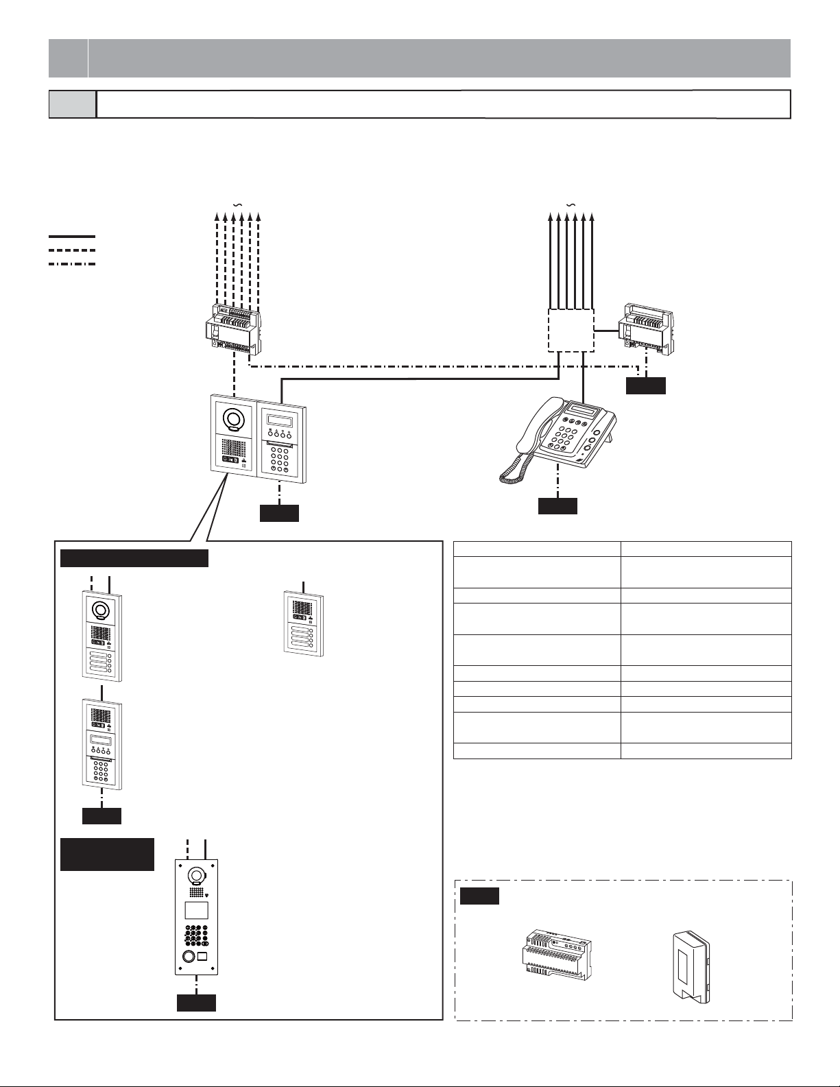
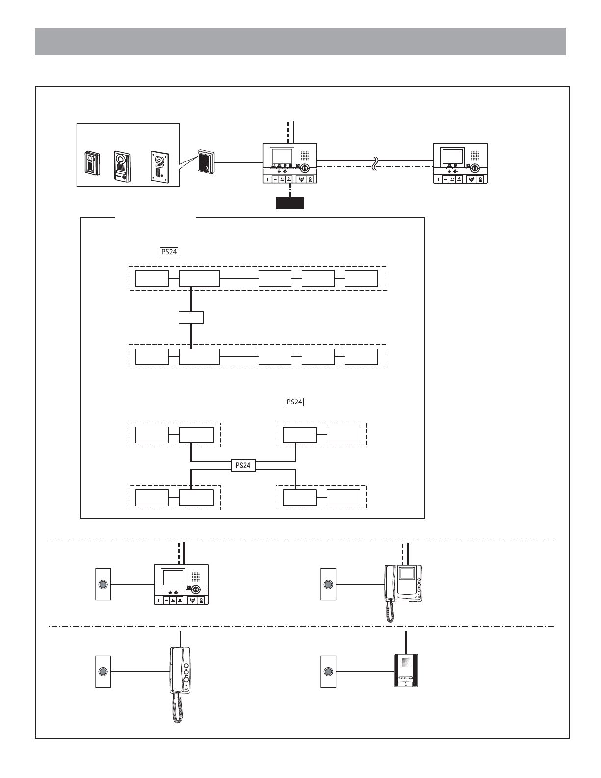
Standard system configuration1-1
This system is constructed with a 2-line communication system and a 2-line video system and requires minimal work for installation. The system is
constructed with video trunk lines consisting of a maximum of 6 trunks from the video bus control system and communication trunk lines that use a
distribution point from a bus control unit. In addition, systems with audio only can be configured.
Common area
: Audio signal line (1)
: Video signal line (1)
: Power supply line (1)
Entrance Station (Unit type)
Audio/video + direct select type
Ex.) GT-VA + GT-DA-L/GT-DA +
GT-SW
Audio + 10 key type
Ex.) GT-
DA-L/GT-DA +
1
2
A
3
C
D
B
F
E
4
G
5
I
J
H
6
L
M
K
O
N
P
7
8
S
Q
T
W
R
9
V
U
Z
X
Y
0
GT-NS-V/GT-NS, GT-10K
PS24
Entrance Station
(Integrated type)
Residence trunks
#1 #6
Video bus control unit
GT-VBC
1
4
G
H
P
7
Q
PS24
Entrance station
Audio/video + 10 key type
2
A
3
C
D
B
F
E
5
I
J
6
Ex.) GT-VA + GT-DA-L/GT-DA +
L
M
K
O
N
8
S
T
W
R
9
V
U
Z
X
Y
0
GT-NS-V/GT-NS, GT-10K
Audio + direct select
type
Ex.) GT-DA-L/GT-DA +
GT-SW
Residence trunks
#1 #6
DP: Distribution Point
DP
Bus control unit
GT-BC
PS24
1
2
A
C
B
3
D
F
E
4
G
I
H
5
J
L
K
6
M
O
N
P
7
Q
S
R
8
T
V
U
W
9
X
Z
Y
0
Security guard station
GT-MK
PS24
Capacity
Entrance station Maximum 5 stations (maximum 3 sta-
Security guard station Maximum 2 stations
Residential station Maximum 48 stations (maximum 25
Residential stations in the same residence (other than GT-2C)
4-way video junction unit (see page 6) Maximum 6 units per trunk
Bus control unit Maximum 1 unit
Video bus contr
ol unit Maximum 1 unit
Master stations in the same residence
(GT-2C)
Sub master monitor station Maximum 3 stations
*1 If an external door release button is connected to a direct select type
entrance station, a maximum of 3 stations can be connected to a
standard system.
*2 The maximum is 100 stations with the GT-1D and GT-1M-L only.
(GT-1D: Maximum 50 stations per trunk
GT-1M-L: Maximum
25 stations per trunk)
tions per trunk) *1
stations per trunk) *2
Maximum 4 stations (2 monitor stations)
Maximum station
PS24
GT-DMV (Guidance-enabled +
VIGIK-linked type)
GT-DM (Guidance-enabled type)
- 4 -
PS24
Power supply
PS-2420,PS-2420S,
PS-2420ULPS-2420DIN
Page 5
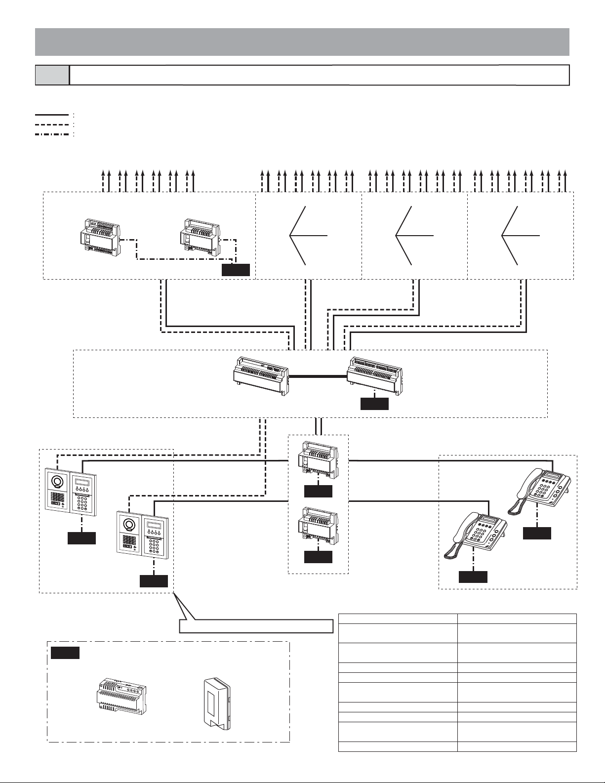
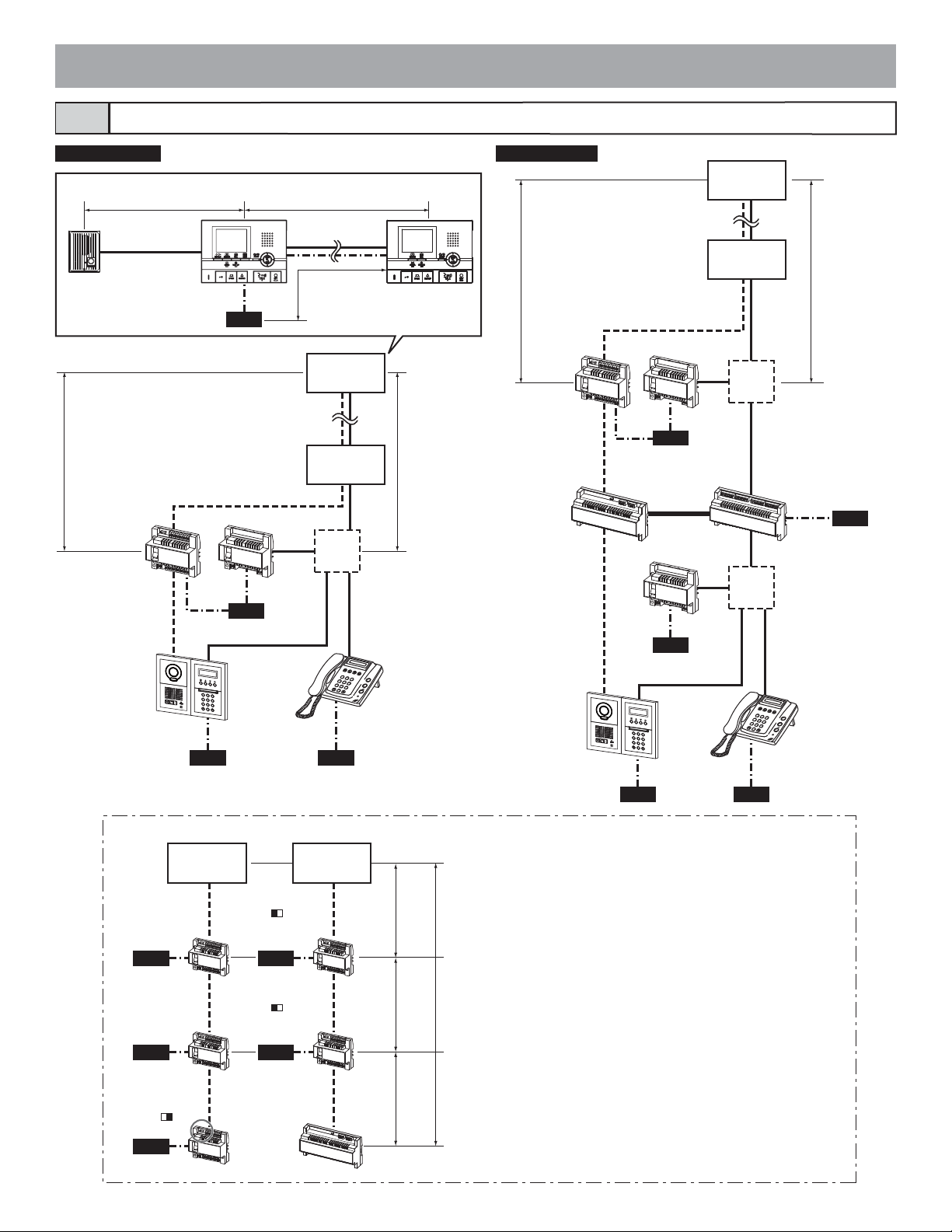
Expanded system configuration diagram1-2
The wiring of the sub trunk line is the same as the standard system.
Common area
Audio signal line (1)
Video signal line (1)
Power supply line (1)
Residence trunks
Video bus control unit
Bus control unit
GT-VBC
Sub trunk line 1A
Expanded video bus control unit
Residence trunks
Residence trunks
Residence trunks
#6#1 #2 #3 #4 #5 #6#1 #2 #3 #4 #5 #6#1 #2 #3 #4 #5 #6#1 #2 #3 #4 #5
GT-BC
PS24
Sub trunk line 1B
GT-VBX
Sub trunk line 2A
Expanded bus control unit
GT-BCX
Sub trunk
line 2B
PS24
PS24
PS24
1
2
A
3
C
D
B
F
E
4
G
5
I
J
H
6
L
M
K
O
N
P
7
8
S
Q
T
W
R
9
V
U
Z
X
Y
0
Entrance station
Power supply
1
2
A
3
C
D
B
F
E
4
G
5
I
J
H
6
L
M
K
O
N
P
7
8
S
Q
T
W
R
9
V
U
Z
X
Y
0
PS24
Common trunk line 1
Common trunk line 2
* See page 4 for various types.
PS-2420,PS-2420S,
PS-2420ULPS-2420DIN
PS24
PS24
Bus control unit
GT-BC
Entrance station Maximum 16 stations (up to 8 sta-
Residential stations per sub trunk
line
Security guard station Maximum 4 stations
Residential station Maximum 500 stations
Residential stations in the same residence (other than GT-2C)
Bus control units per common trunk line
Bus
Master stations in the same residence
(GT-2C)
Sub master monitor station Maximum 3 stations
- 5 -
Common trunk line 1
Common trunk line 2
1
2
A
C
B
3
D
F
E
4
G
I
H
5
J
L
K
6
M
O
N
P
7
Q
S
R
8
T
V
U
W
9
X
Z
Y
0
PS24
Security guard station
GT-MK
Capacity
tions per trunk)
Maximum 125 stations (up to 25 stations per trunk)
Maximum 4 stations (2 monitor stations)
Maximum 1 unit
control units per sub trunk line Maximum 1 unit
Maximum station
1
2
A
C
B
4
G
I
H
5
J
L
K
6
M
N
P
7
Q
S
R
8
T
V
U
W
9
X
Z
Y
0
PS24
3
D
F
E
O
Page 6
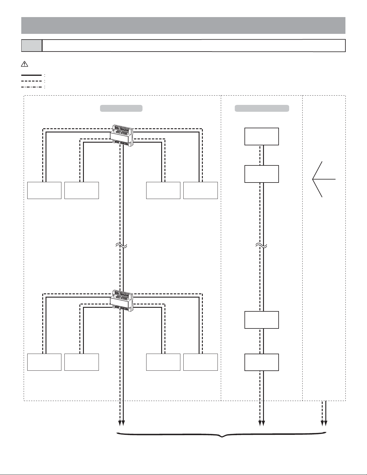
Residential station configuration1-3
For wiring from the control units to each residence, station-to-station wiring or star wiring using a 4-way video junction unit is possible.
Mixing on the same trunk line is not possible.
Audio signal line (1)
Video signal line (1)
Power supply line (1)
Trunk line #1
Each
residence
Each
residence
Homerun wiring Station-to-station wiring
4-way video junction unit
GT-4Z
Each
residence
Each
residence
Each
residence
Each
residence
Trunk line #3 to #6 Trunk line #2
Each
residence
Each
residence
4-way video junction unit
GT-4Z
Each
residence
Each
residence
To each control unit
Each
residence
Each
residence
- 6 -
Page 7
Each residence (with recording function)
Video door station
JK-DA JK-DV JK-DVF
A
I
P
H
O
NE
J
F
-D
VF
Power supply-related
[When sub master monitor stations are connected]
If even just one sub master monitor station is connected, it is possible to supply power to up to 2
residences with 1
However, wiring must be connected from near the terminals of the power supply for each residence.
Residence 1
Door
station
Door station
or doorbell
GT-D
power supply.
Master monitor
station
PS24
PS24
Sub master
monitor station
Master monitor station
(with recording function)
GT-2C-L, GT-2C
Sub master
monitor station
Sub master
monitor station
Sub master monitor
station
GT-2H-L, GT-2H
Residence 2
[When sub master monitor stations are not connected]
It is possible to supply power to up to 4 residences with 1
However, wiring must be connected from near the terminals of the power supply for each residence.
Residence 1 Residence 3
Residence 2 Residence 4
Each residence (with monitor)
Doorbell Doorbell
Each residence (with audio)
Doorbell Doorbell
Door
station
Door
station
Door
station
Master monitor
station
Master monitor
station
Master monitor
station
Residential monitor station
GT-1C-L, GT-1C
Residential station
GT-1D
Sub master
monitor station
Master monitor
Master monitor
Sub master
monitor station
power supply.
station
station
Sub master
monitor station
Door
station
Door
station
Residential monitor station with
handset
GT-1M-L
Residential station
GT-1A
- 7 -
Page 8
Wiring distance1-4
Standard system Expanded system
Each residence (with recording function)
[12] [13]
[14]
[15]
PS24
[6] [5]
Each
residence
Each
residence
GT-VBC GT-BC
Entrance station
Each
residence
Each
residence
*
[1]
DP
[8]
[3] [4]
[10] [11]
PS24
[9]
[2]
4
G
H
P
7
Q
S
R
1
2
A
3
C
D
B
F
E
4
G
5
I
J
H
6
L
M
K
O
N
P
7
8
S
T
Q
W
R
9
V
U
Z
X
Y
0
0
PS24 PS24
1
2
A
C
B
3
D
F
E
I
5
J
L
K
M
6
O
N
8
T
V
U
W
9
X
Z
Y
[5][6]
GT-MK
GT-VBC
Entrance station
*
GT-BC
[8]
PS24
[18]
[9]
GT-BC
[20]
[8]
PS24
[19]
1
2
A
3
C
D
B
F
E
4
G
5
I
J
H
6
L
M
K
O
N
P
7
8
S
T
Q
W
R
9
V
U
Z
X
Y
0
[10] [11]
PS24 PS24
[1]
[1]
DP
DP
[17]
GT-BCXGT-VBX
1
4
G
I
H
5
J
K
P
7
Q
S
R
8
T
V
U
0
[16]
PS24
2
A
C
B
3
D
F
E
GT-MK
L
M
6
O
N
W
9
X
Z
Y
*
Each
residence
EXP STD
residence
SW2
GT-VBC
PS24
PS24
SW2
EXP STD
GT-VBC
PS24
SW2
EXP STD
PS24
GT-VBC
PS24
Standard system Expanded system
Each
GT-VBC
GT-VBC
GT-VBX
[7]
[7]
[7]
The GT-VBC can be used as an extension adaptor as well (2
units per trunk line).
To do so, set the setting switch (SW2) to "EXP".
Use the unit as an extension adaptor in expanded systems.
Even if two units are used as extension adaptors (SW2:
EXP), the wiring distance to the farthest residential station
from the GT-VBC (SW2: STD) or GT-VBX is limited to 300 m.
300 m
- 8 -
Page 9
Wiring distance
[1] GT-BC - DP *2 3 m (10') 5 m (16') 5 m (16')
[2] Entrance station - DP *2 150 m (490') 300 m (980') 300 m (980')
[3] Entrance station - GT-VBC 150 m (490') 300 m (980') 300 m (980')
[4] GT-MK - DP *2 150 m (490') 300 m (980') 300 m (980')
[5] DP *2 - farthest residential station (includes system with GT-4Z) 150 m (490') 300 m (980') 300 m (980')
GT-VBC - farthest residential station (includes system with GT-4Z) 100 m (330') 150 m (490') 150 m (490')
[6]
[7] GT-VBC (SW2: STD) - GT-VBC (SW2: EXP) 100 m (330') 150 m (490') 150 m (490')
[8] GT-BC - power supply 3 m (10') 5 m (16') 5 m (16')
[9] GT-VBC - power supply 3 m (10') 5 m (16') 5 m (16')
[10] Entrance station - power supply 150 m (490') 300 m (980') 300 m (980')
[11] GT-MK - power supply 150 m (490') 300 m (980') 30
[12] Door station - GT-2C-L, GT-2C 50 m (165') 100 m (330') 100 m (330')
[13] GT-2C-L, GT-2C - farthest GT-2H-L, GT-2H 50 m (165') 100 m (330') 100 m (330')
[14] GT-2C-L/GT-2C - power supply 25 m (82') 50 m (165') 75 m (245')
[15] GT-2H-L, GT-2H - power supply 50 m (165') 100 m (330') 150 m (490')
[16] GT-BCX - power supply 3 m (10') 5 m (16') 5 m (16')
[17] GT-BCX - GT-BC 150 m (490') 300 m (980') 300 m (980')
T-VBX - GT-VBC (SW2: EXP) 100 m (330') 150 m (490') 150 m (490')
[18] G
[19] Entrance station - GT-BCX 150 m (490') 300 m (980') 300 m (980')
[20] Entrance station - GT-VBX 150 m (490') 300 m (980') 300 m (980')
GT-NS-V, GT-DMV - (VIGIK) 5 m (16') 10 m (33') 10 m (33')
Standard system total wiring distance *1 1650m (5400') 2500m (8200') 2500m (8200')
Expanded system Total wiring distance per common line (maximum 2 trunk
es)
lin
Expanded system Total wiring distance per sub trunk line (maximum 4 trunk
lines)
GT-RY - transfer source unit 5 m (16') 10 m (33') 10 m (33')
GT-2C-L, GT-2C - external monitor 1.5 m (5') 3 m (10') 3 m (10')
Entrance station - surveillance camera Coaxial cable 15 m (50')
Wire diameter
0.65 mm
(22 AWG)
1650 m (5400') 2500 m (8200') 2500 m (8200')
1650 m (5400') 2500 m (8200') 2500 m (8200')
0.8 mm
(20 AWG)
1.0 mm
(18 AWG)
0 m (980')
*1 The track lengths from a door station to a GT-2C-
L or GT-2C and from a GT-2C-L or GT-2C to a door station are not included in the total wiring distance.
*2 DP = Distribution Point
- 9 -
Page 10
2
COMPONENTS
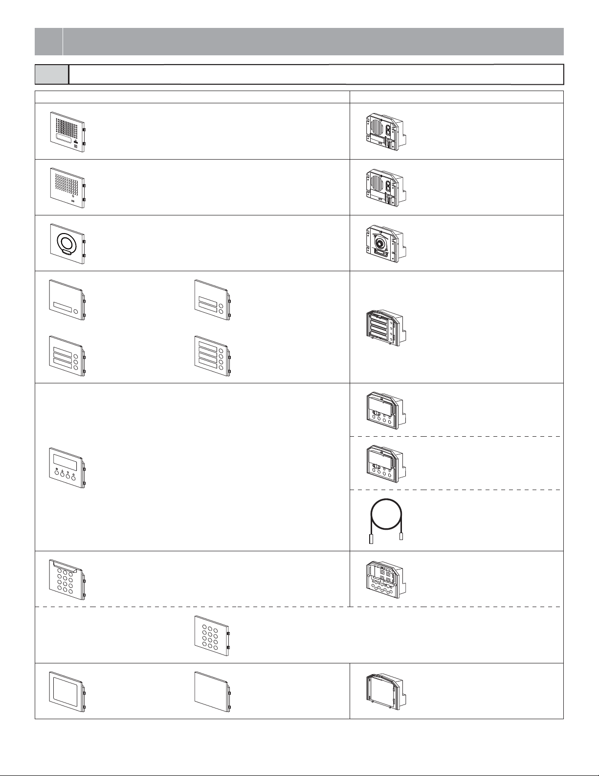
Entrance Station (Unit type)2-1
Panel Module
Speech module panel
(guidance-enabled type) GT-DP-L
Speech module panel
GT-DP
Camera module panel
GT-VP
1-call button panel
GF-1P
3-call button panel
GF-3P
Speech module (guidance-enabled
type)
GT-DA-L (connector included)
Speech module
GT-DA
(connector included)
Camera module
GT-VA
(connector included)
2-call button panel
GF-2P
Switch module
GT-SW
(connector, name card included)
4-call button panel
GF-4P
Name scrolling module
(VIGIK-linked type)
GT-NS-V (connector included)
Name scrolling module panel
GT-NSP-L
10 key module panel
GF-10KP
Address module panel
GF-AP
Access control keypad module with panel
GT-AC
Blank panel
GF-BP
Name scrolling module
GT-NS
USB cable A-B type (1 m)
(GT-NS-V, GT-NS included)
10 key module
GT-10K
Address module
GT-AD
(address card, address cover included)
- 10 -
Page 11
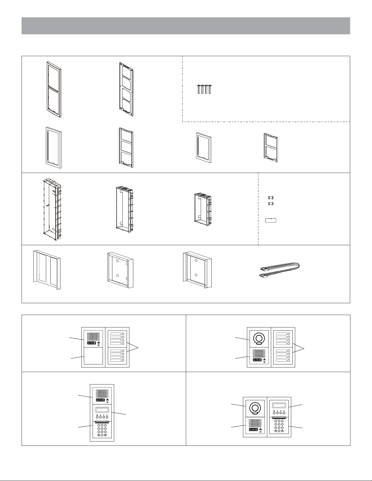
Mounting parts
4-module front
frame
GT-4F
3-module front
frame
GF-3F
4-module back box
GT-4B
Mounting bracket
(included with
GT-4F)
Mounting bracket
(included with
GF-3F)
3-module back box
GF-3B
Screws
2-module front
frame
GF-2F
2-module back
box
GF-2B
Mounting bracket
(included with GF-2F)
Joint pipe
Mounting gauge
Rain hood
GT-nH
* A number appears in place of n.
Combination examples
Audio only, Direct select type (8 stations)
GT-DP-L/GT-DP+
GT-DA-L/GT-DA
GF-BP
Audio only, 10 key type
GT-DP-L/GT-DP+
GT-DA-L/GT-DA
GF-10KP+
GT-10K
Surface-mount box
GF-nBA
Hooded surfacemount box
GT-nHB
80 cm (32") connection cable
GF-C
Audio/video, Direct select type (8 stations)
GT-VP+GT-VA
GF-4P+GT-SW
GF-4P+GT-SW
GT-DP-L/GT-DP+
GT-DA-L/GT-DA
Audio/video, 10 key type
GT-VP+GT-VA
GT-NS-V/GT-NS+
2
GT-NSP-L
3
1
D
A
F
C
B
E
5
4
6
M
G
J
I
L
O
K
H
N
8
9
7
W
P
Z
S
T
Q
V
X
U
Y
R
0
GT-DP-L/GT-DP+
GT-DA-L/GT-DA
2
3
1
D
A
F
C
B
E
5
4
6
M
G
J
I
L
O
K
H
N
8
9
7
W
P
Z
S
T
V
Q
X
U
Y
R
0
GT-NS-V/GT-NS+
GT-NSP-L
GF-10KP+
GT-10K
- 11 -
Page 12
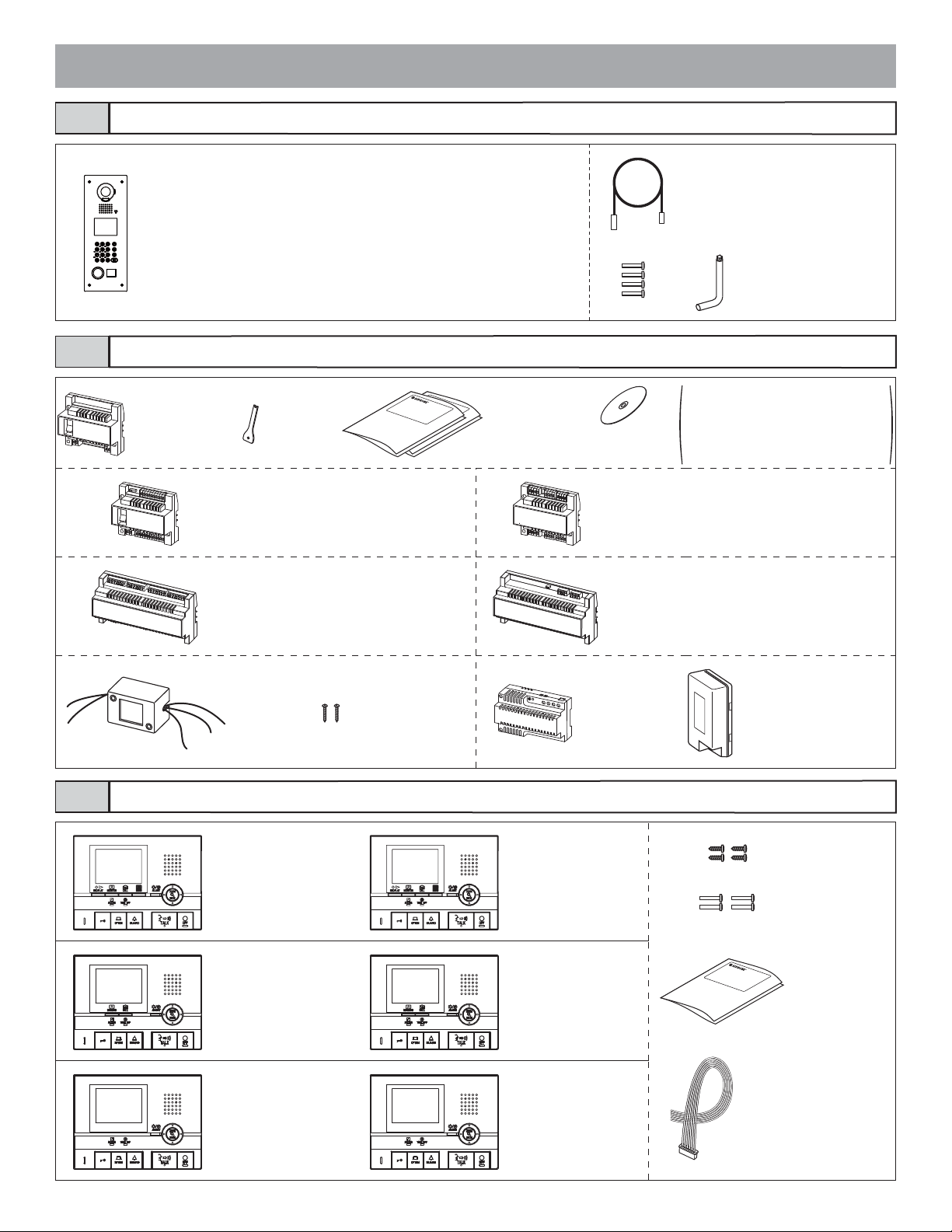
2-2
Entrance Station (Integrated type)
2-3
Flush mount entrance station (name scrolling, guidance-enabled, VIGIK-linked
type)
GT-DMV
Flush mount entrance station (name scrolling, guidance-enabled)
GT-DM
Bus control unit etc.
Bus control unit
GT-BC
Special
screwdriver
Video bus control unit
GT-VBC
Expanded bus control unit
GT-BCX
(mounting bracket included)
English, French
installation manual
USB cable A-B type (1 m)
Screws Special screwdriver
• Installation manual
CD
Entrance station + security guard station operation manual
•
• GT-2C (-L) GT-2H (-L) operation manual
• GT-1C (-L) operation manual
• GT-1M-L operation manual
• GT-1D operation manual
• Setup tool
4-way video junction unit
GT-4Z
Expanded video bus control unit
GT-VBX
(mounting bracket included)
2-4
External
signaling relay
GT-RY
Residential station
Master monitor station
(with recording function,
hearing aid-compatible)
GT-2C-L
Sub master monitor
station (hearing aidcompatible)
GT-2H-L
Residential monitor
station (hearing aidcompatible)
GT-1C-L
Wood mounting
screws
Power supply
PS-2420DIN
Master monitor station
(with recording function)
GT-2C
Sub master monitor
station
GT-2H
Residential monitor
station
GT-1C
Power supply
PS-2420, PS-2420S,
PS-2420UL
Wood mounting screws
Screws
Operation manual
(GT-2C-L, GT-2C only)
Option connector
(not included with
GT-2H-L, GT-2H)
- 12 -
Page 13
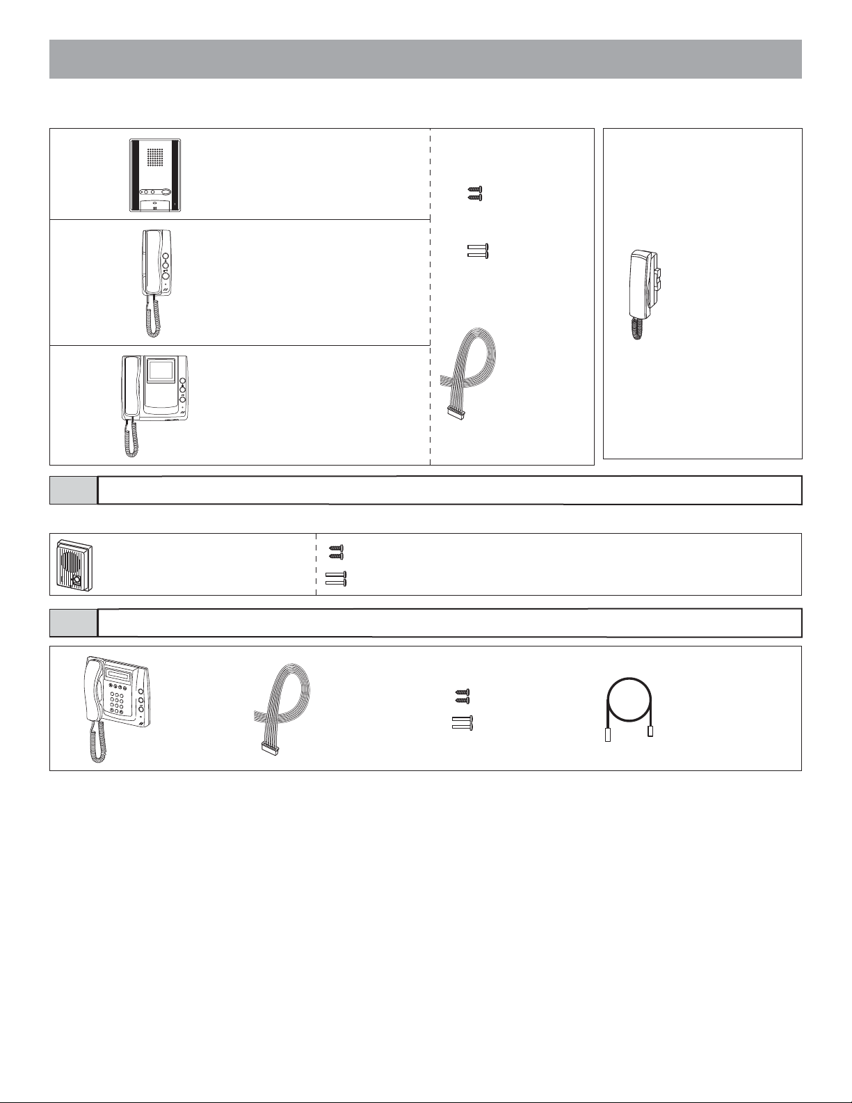
Residential station
GT-1A
Residential station
GT-1D
Residential monitor station with
handset
GT-1M-L
Wood mounting
screws
Screws
Optional handset
GT-HS
Option connector
2-5
Door station
For door stations other than the GT-D, see the instruction manual for that door station.
Wood mounting screws
Screws
2-6
Door station
GT-D
Security guard station
1
2
A
3
C
B
D
F
E
4
G
5
I
H
J
L
K
P
7
Q
S
8
R
T
V
U
0
6
M
N
O
W
9
X
Z
Y
Security guard
station
GT-MK
Option connector
Wood mounting
screws
Screws
USB cable A-B type (1 m)
- 13 -
Page 14
3
MOUNTING
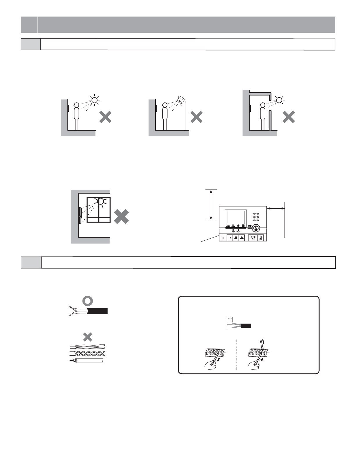
3-1
• For video entrance stations and video door stations, the picture quality of residential station monitoring is affected by the nature of the external light
from above and the surrounding area of the built-in cameras, so do not install these stations in the types of locations shown below.
• Locations exposed to direct sunlight
• Locations under street lights or door lights
• Other locations exposed to strong light
• Install master monitor stations and sub master monitor stations in places where the screen is not exposed to direct sunlight.
• A switch
Allow open space of 5 cm (2").
• At least 15 cm (6") of vertical open space from the center of the mounting bracket is needed for mounting the master monitor station or sub master
monitor station.
• Entrance stations (Integrated type) include a sensor. Do not places objects such as plants or trees in places monitored by the sensor.
Also, placing the unit in bright sunlit areas may prevent the sensor from working properly.
Mounting locations
is located on the right side of the GT-2C-L/GT-2C, GT-2H-L/GT-2H, and GT-1C-L/GT-1C.
15 cm
(6")
5 cm
(2")
Master monitor station
Sub master monitor station
3-2
• Use PE (polyethylene)-insulated PVC jacket cable.
Parallel or jacketed 2-conductor, mid-capacitance non-shielded cable is recommended.
• Never use individual conductors, twisted pair cable or coaxial cable.
Appropriate cable
(x2)
Weak electrical current line connection
Length is 8 mm for the GT-DA-L/GT-DA, GT-DMV/GT-DM, GT-2C-L/GT-2C,
GT-2H-L/GT-2H, GT-1C-L/GT-1C, GT-BCX, GT-VBX, and GTW-LC; and 9 mm
for other units.
Insert the wire into the direct terminal. If it is difficult to insert the wire, insert it while
pressing the release button.
- 14 -
Page 15
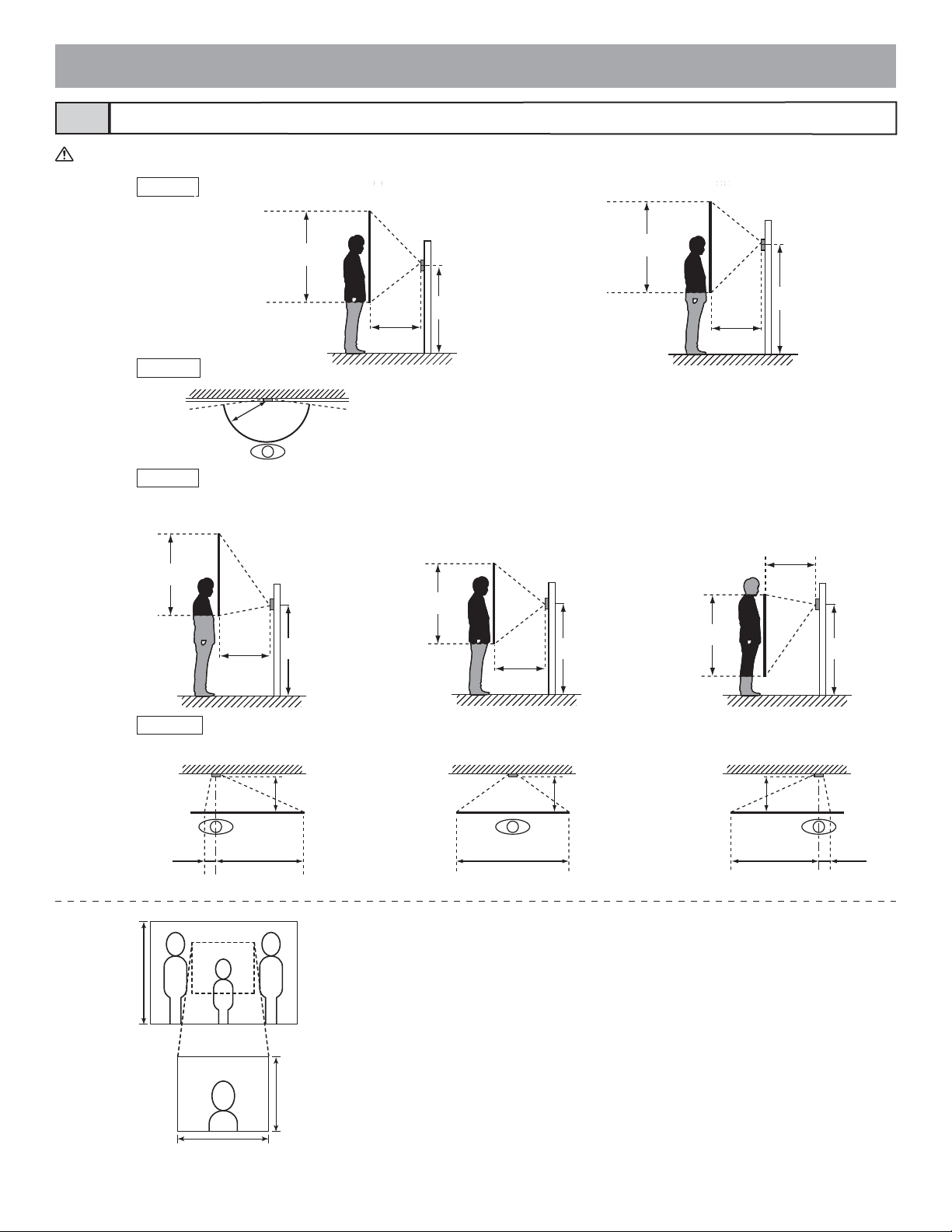
Mounting positions and image view area3-3
When using the camera module, if the rain hood is attached a portion of it will show up in the camera display.
Wide picture
Up/Down
Approx. 1800 mm
Approx. 750 mm
Mounting position 1350 mm (4' 4")
(5' 11")
Approx. 1050 mm (3'5")
(2' 5")
Approx. 2000 mm
amera center
C
1350 mm (4'4")
(6' 7")
Approx. 1050 mm (3'5")
Approx. 950 mm
(3' 2")
Mounting position 1550 mm (5' 1")
Camera center
1550 mm (5'1")
Left/Right
Zoom picture
Approx. 2050 mm
Approx. 850 mm (2'9")
Approx. 1200 mm
Up/Down
(6' 9")
(4')
Left/Right
500 mm (20")
Approx. 170°
500 mm (20")
An area over a range of approx. 170° in a 500 mm radius from the camera displays.
500 mm
(20")
(The display range is a rough estimation and may change due to the installation environment.)
(with mounting position of 1350 mm (4'4"))
Zoom <Up> Zoom <Center> Zoom <Down>
500 mm (20")
500 mm (20")
Approx. 1650 mm
(5' 5")
Camera
center
1350 mm (4'4") 1350 mm (4'4") 1350 mm (4'4")
Approx. 700 mm (2'3")
Approx. 950 mm
(3' 1")
500 mm (20")
Approx. 1400 mm
Camera
center
(4' 7")
Approx. 850 mm (2'9")
Approx. 550 mm
(1' 9")
Zoom <Left> Zoom <Center> Zoom <Right>
500 mm (20")
500 mm (20") 500 mm (20")
Camera
center
Approx.
1050 mm
(3' 5")
Approx.
1300 mm
(4'3")
Approx. 100 mm (4")
Approx. 900 mm (3')
Approx. 700 mm
(2' 3")
Approx.
1300 mm (4'3")
Approx. 900 mm (3')
Approx. 100 mm (4")
Objects appear smaller due to greater distortion in the surrounding sections compared to
the central section, but a wider area is displayed.
The display range is a rough estimation and may change due to the installation environment.
The zoom position can be changed.
At the time of shipment, the zoom position is set at "Zoom central".
- 15 -
Page 16
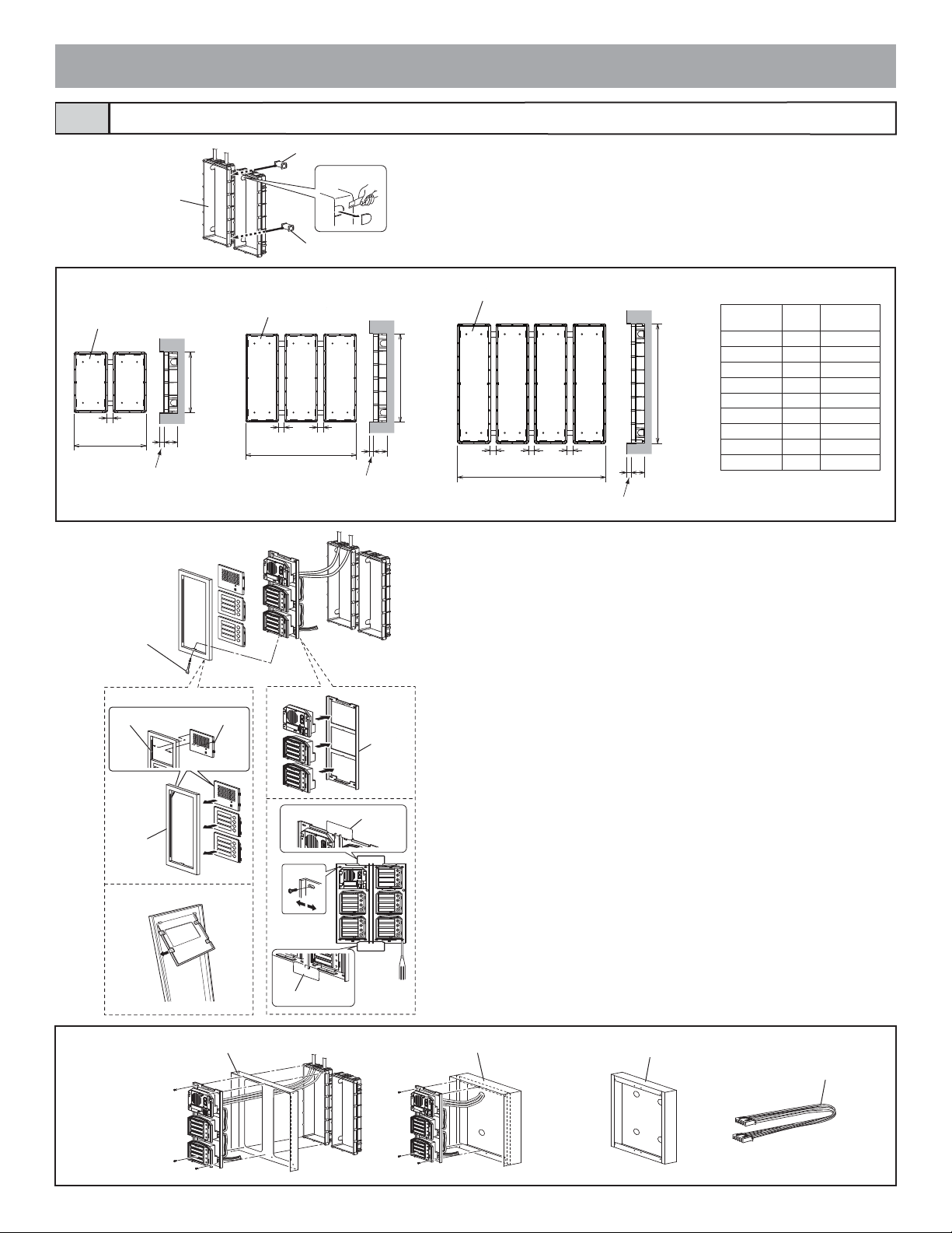
Entrance Station (Unit type)3-4
Back box
Joint pipe
2
1
Joint pipe
Make a hole for the cable.
1
2 Use the joint pipe to assemble the back box.
• Make sure the back box is mounted level.
Back box assembly dimensions
Holder
Back box GF-3B
25 mm
(1")
54
W
25 mm
(1")
15 mm
*
(9/16")
Back box GF-2B
200 mm
(7-7/8")
25 mm
(1")
W
* Do not mount the back box on a surface that is
15 mm
*
(9/16")
44 mm
(1-3/4")
recessed by 15 mm (1/2") or more from the external surface of the wall.
3
Special screwdriver
(enclosed with
GT-BC)
Slot
44 mm
(1-3/4")
Mounting
bracket
295 mm
(11-5/8")
Back box GT-4B
GF-2B/3B
GT-4BW(mm)W(inch)
x 1 110 4-5/16"
x 2 245 9-5/8"
400 mm
(15-3/4")
x 3 380 15"
x 4 515 20-1/4"
x 5 650 25-9/16"
x 6 785 30-7/8"
x 7 920 36-1/4"
x 8 1055 41-9/16"
25 mm
25 mm
(1")
(1")
25 mm
(1")
W
15 mm
*
(9/16")
44 mm
(1-3/4")
x 9 1190 46-7/8"
3 Assemble the module.
• For the useable modules, see 2-1.
• The GT-SW can have up to 6 modules.
To connect 7 or more modules or to increase the light intensity, please con-
tact Aiphone.
4 Mount each module panel to the front frame.
• Mount the panels from behind the front frame.
• Insert the holders into the slots on both sides.
(With the GT-4F, mount the module panels so that they catch on the tabs in
order from top to bottom.)
Options
Front frame
GF-4F
Rain hood GT-203H
Mounting gauge
Mounting gauge
5 Mount each module, except the GT-AC, to the mounting brack-
et.
• Set the modules in the mounting bracket until they click in place.
• To mount multiple rows of modules, apply the mounting gauge to the
mounting bracket.
While using the mounting gauge to make adjustments, tighten the screws.
(A mounting gauge is included with the GF-2B, GF-3B, and GT-4B built-in
back box.)
Hooded surface-mount box GT-203HB
- 16 -
Surface-mount box GF-203BA
80 cm (32") connection cable GF-C
Page 17
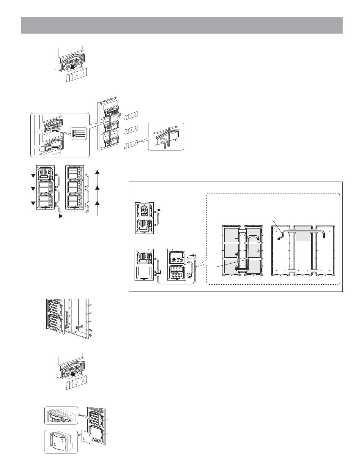
6
GT-DA-L/GT-DA
ON
1
4
CN
23
1
2
CN
3
0
1
6 Remove the terminal cover.
7
N
O
4
3
2
1
3
0
1
GT-DA-L/GT-DA
ON
4
3
CN2
CN1
12
3
0
1
ON
GT-SW
N
O
N
O
2
1
8
CN2
CN1
7 From the speech module to the next module, insert the attached connector into the
socket.
Make sure to run the cable under the terminal cover for protection.
8 Connect the connectors between the modules with cables.
Mount modules on the back boxes.
CN1
CN2
CN1
CN2
CN2
CN1
CN2
CN1
Example of interconnection of modules
GT-VA
GT-DA-L/GT-DA
GT-DA-L/GT-DA
CN3
CN1
GT-NS-V/GT-NS
CN2
CN1
CN1
CN3
Use the GF-C to connect to the name scrolling module.
To position the speech module in the center row, run the
GF-C through the joint pipe in advance.
GT-VA
GT-DA-L
/GT-DA
GT-AD GF-BP
GF-C
GT-NS-V
/GT-NS
GT-10K
GF-C
GT-DA-L
/GT-DA
GF-3B GF-3B GF-3B
9
10
11
GT-DA-L/GT-DA
ON
1
CN
34
2
1
2
CN
3
0
1
GT-SW
GT-AD
GF-3B GF-3B
GT-AD
CN2
CN100
GT-10K
9 Run the connection cable through the joint pipe (which you should have made open in
advance) and connect CN1 of the GT-SW to the next row.
10 Put back the terminal cover.
Mount the front frame and tighten with the special screwdriver (enclosed with GT-
BC).
11 For the GT-SW and GT-AD, remove the resident name/address plate or paper by
pressing either the left or right end. (Peel off the plastic film.)
Use a permanent pen to write the resident name and address on the transparent plate
and mount the plate on the module.
- 17 -
Page 18
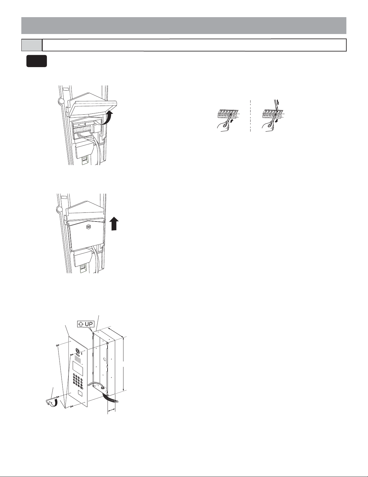
GT-DMV
GT-DM
Entrance Station (Integrated type)3-5
1
2
1 Open the cover and connect the wiring to the terminal block.
Insert the wire into the direct terminal. If it is difficult to insert the wire, insert it while
pressing the release button.
2 Close the cover until it clicks into place.
3
Special
screwdriver
4
Unit
Mounting screws
×4
Flush mount
back box
125 mm (4-15/16")
380 mm (15")
60 mm (2-3/8")
3 Mount the unit in the flush mount back box.
4 Tighten the locking screws using the special screwdriver.
- 18 -
Page 19

Bus control unit, 4-way video junction unit and power supply3-6
DIN rail mounting
The length of the connecting cable between the GT-BCX and GT-VBX is 40 cm. Therefore, mount them adjacently to each other.
1 Mount the unit on the DIN rail. Click the unit into place.
2 When removing the unit, pull the lock release lever down.
* When the system does not operate properly, check the wiring.
Turn off the GT-BC and GT-VBC power switch and then turn the switch back on after four seconds.
This will reset the entire system.
GT-BC
GT-VBC
ON
OFF
*
Power switch
Power on LED
11 1
DIN rail DIN rail
DIN rail
GT-4Z
2
Lock release lever
Direct mounting to wall surfaces
Use the wall mounting screws to mount the unit to a wall surface.
The GT-BCX and GT-VBX cannot be mounted directly to a wall surface.
GT-BC
GT-VBC
Wall mounting screws
Screw hole
GT-4Z
Screw hole
Screw hole
Wall mounting screws
DIN rail
2
Lock release lever
Screw hole
GT-BCX
GT-VBX
DIN rail
2
Lock release lever
PS-2420DIN
1
PS-2420
PS-2420S
PS-2420UL
DIN rail
DIN rail
Mounting bracket
1-gang box
83.5 mm
(3-5/16")
- 19 -
Page 20

Residential station3-7
GT-2C-L
GT-2C
GT-2H-L
GT-2H
GT-1C-L
GT-1C
Mounting screws ×4
1. Press the release button
(to insert or remove the wire).
2. Insert the cable into the terminal.
• To remove the terminal block, slide the
terminal block and pull it out.
• Strip away the jacket of the cable and insert all wires into the slots in an orderly
fashion. Failure to do so could result in
pinching that may damage the wiring.
1
Surface wiring
* When a 3-gang box is not mounted, the cable can be routed as surface
wiring to the top or bottom of the unit.
Cut a cable inlet on the upper part of the unit to allow passage of the
wiring into the unit.
If there is a large amount of wiring, strip away the jacket of the cable
up to the cable inlet.
Mounting bracket
2
8 mm
(3/8")
Mounting screws ×4
3-gang box
83.5 mm
(3-5/16")
83.5 mm
(3-5/16")
* To pass the cable through the back of
the unit, cut out the cable inlet.
Optional handset
Mounting bracket
Screws (×2)
Handset GT-HS
Chassis
Station unit joint connector
Connect the station unit joint
connector.
- 20 -
Page 21

GT-1A
1
Mounting screws
Mounting bracket
1-gang box
1 Mount the mounting bracket on the 1-gang box or round back box.
83.5 mm (3-5/16")
OR
60 mm (2-3/8")
(Forendusers)
9
0
651
0.
KE
K
CE
C
Round back box
Terminal block
2 Connect the wiring to the terminal block.
• To remove the terminal block, slide the terminal block and pull it out.
• Strip away the jacket of the cable and insert all wires into the slots in an orderly
fashion. Failure to do so could result in pinching that may damage the wiring.
• For surface wiring, cut out the cable inlet.
Mounting screws
2
SW1 A B
Donotremovethewires(Forendusers)
0.6510 9
IN OUT
R1 R2 R1 R2 C
CE K KE
vethewires
o
Donotrem
T
OU
IN
AB
R2
1
SW
R1
R2
R1
3
3 Mount the station unit to the mounting bracket.
- 21 -
Page 22

GT-1D
Chassis
1
1-gang box
1 Mount the station unit to the chassis or mounting bracket.
GT-1M-L
Screws
83.5 mm (3-5/16")
2
2 Connect the wiring to the terminal block.
OR
60 mm (2-3/8")
3
2
1
Terminal block
Mounting screw
Screws
Round back box
Mounting bracket
1-gang box
83.5 mm (3-5/16")
OR
60 mm (2-3/8")
Round back box
3
GT-1M-L:
• To remove the terminal block, slide the terminal block and pull it out.
• Strip away the jacket of the cable and insert all wires into the slots in an orderly
fashion. Failure to do so could result in pinching that may damage the wiring.
3 Mount the station unit to the chassis or mounting bracket.
• For surface wiring, cut out the cable inlet.
Door station3-8
For door stations other than the GT-D, see the included instructions.
GT-D
12
Mounting frame
Mounting
screws ×2
Place " UP" upwards.
83.5 mm (3-5/16")
Do not block the
drainage hole.
1-gang box
1 Loosen the screws and remove the mounting frame and main unit.
2 After connecting the wiring, mount the main unit to the mounting
frame.
• For surface wiring, insert wiring from the cable inlet (lower part).
- 22 -
Page 23

Security guard station3-9
GT-MK
Peel off the protection film on the display.
Desk-top mounting using the GFW-S stand
12
Mounting
bracket
Protective cover
Screws included with GFW-S (×4)
Mounting bracket
1 Separate the mounting bracket and the protective cover from the
back of the unit.
2 Mount the mounting bracket to the GFW-S as shown in the draw-
ing.
Cable tie included with the GFW-S
34
3 Strip away the jacket of the cable and insert all wires into the slots
in an orderly fashion while connecting them to the terminal block.
Failure to do so could result in pinching that may damage the wiring.
4 Set the wiring in place with the cable tie to ensure that they are not
pulled out.
56
Protective cover
Mounting bracket
5 Cover the terminal section with the protective cover.
6 Insert the mounting bracket latch and slide it upward until it locks.
Wall mounting
2
Terminal block
Mounting bracket
1 Mount the mounting bracket on the 1-gang box or round back box.
2 Connect the wiring to the terminal block.
Mounting screws
1
×2
1-gang box
83.5 mm (3-5/16")
• To remove the terminal block, slide the terminal block and pull it out.
• Strip away the jacket of the cable and insert all wires into the slots in an orderly
fashion while connecting them to the terminal block. Failure to do so could result
in pinching that may damage the wiring.
3
Wiring slot
OR
60 mm (2-3/8")
Round back box
3 Mount the unit to the mounting bracket.
• For surface wiring, cut out the cable inlet.
- 23 -
Page 24

4
WIRING
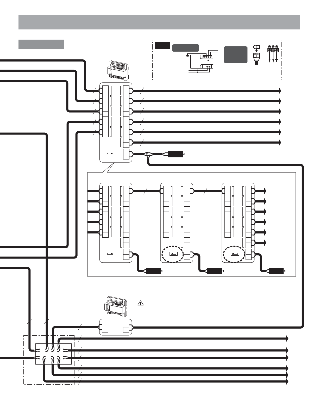
Standard system for common area4-1
Entrance
station
Entrance station #1 to #3
Ex.) Unit type
GT-DA-L/GT-DA
SW2: 2~4
ON
2 3
1
4
#3
ON
2 3
1
4
#1
1
2
A
3
C
D
B
F
E
4
G
5
I
J
H
6
L
M
K
O
N
P
7
8
S
Q
T
W
R
9
V
U
Z
X
Y
0
#2#1
ON
2 3
1
4
A1
A2
GT-VAGT-DA-L/GT-DAGT-NS-V/GT-NS
CN4CN6CN5
CN3
CN1
R1
R2
ELB
ELC
ELM
BP
BP
CN2
CN1
+
-
CN3
Put each piece of wiring in a separate sheath as shown in the diagram below.
#2
DP
A1
A2
GT-VAGT-DA-L/GT-DAGT-NS-V/GT-NS
CN4CN6CN5
CN3
CN1
R1
R2
ELB
ELC
ELM
BP
BP
CN2
CN1
+
-
CN3
DP
#3
A1
A2
Brown NTSC (+)
CN4
Red NTSC (-)
GT-VAGT-DA-L/GT-DAGT-NS-V/GT-NS
CN3
CN1
CN6CN5
Purple
R1
R2
ELB
ELC
ELM
BP
BP
CN2
CN1
Orange (D+)
Yellow (D-)
Green (GND)
+
-
CN3
Surveillance camera
Blue
NP
NP
NP
External door release button
VIGIK
* GT-NS-V only
PS24
AC
PT
PT
AC
External signaling relay
GT-RY
Door release
AC/DC
Less than AC/DC 24 V, 4 A
24 V
(resistance load)
PT: AC transformer
NP:
Non-polarized
AC
#4
Entrance station #4 to #5
Ex.) Integrated type
GT-DMV/GT-DM
SW1: 2~4
#4
ON
1
2 3
#5
ON
2 3
1
4
4
Security guard station
G
P
7
Q
S
R
0
SW1: 4
ON
2 3
1
GT-MK
1
2
A
C
B
3
D
F
E
4
I
H
5
J
L
K
6
M
O
N
8
T
V
U
W
9
X
Z
Y
4
#2
#2#1
ON
2 3
1
4
CN100
GT-10K
A1
A2
R1
R2
ELB
ELC
ELM
BP
BP
+
-
CN2
R1
R2
R1
R2
C
CE
+
-
DP
PS24
AC
AC
PS24
#5
#1
CN100
GT-10K
A1
A2
R1
R2
ELB
ELC
ELM
BP
BP
+
-
CN2
R1
R2
R1
R2
C
CE
+
-
NP
NP
External door release button
Brown NTSC (+)
Red NTSC (-)
NP
CN100
GT-10K
Surveillance camera
- 24 -
PT
PT
Orange (D+)
Yellow (D-)
Green (GND)
Doorbell
AC
VIGIK
Door release
AC/DC
Less than AC/DC 24 V, 4 A
24 V
(resistance load)
PT: AC transformer
* GT-DMV only
Blue
Purple
NP
External
signaling relay
GT-RY
AC
1P
NP
Page 25
Bus control unit
Video bus control unit
GT-VBC
PS24
PS-2420DIN
IN 230V~ 50/60Hz
+
24 V DC2A
230 V AC
NL
-
+
2A
N
L
PS-2420
PS-2420S
PS-2420UL
+
100V - 240V -
50/60 Hz
24V DC
2 A
-
1P
NP
1P
NP
1P
NP
1P
NP
1P
NP
EXP
A1
A2
A1
A2
A1
A2
A1
A2
A1
A2
SW2
IN1
IN2 IN3 IN4 IN5
STD
OUT1OUT2OUT3OUT4OUT5OUT6
B1
B2
B1
B2
B1
B2
B1
B2
B1
B2
B1
B2
+
-
1P
NP
1P
NP
1P
NP
1P
NP
1P
NP
1P
NP
PS24
AC
* To use the GT-VBC as an extension adaptor, set the setting switch to [EXP].
EXP
A1
A2
A1
A2
A1
A2
A1
A2
A1
A2
SW2
IN1
IN2 IN3 IN4 IN5
STD
OUT1OUT2OUT3OUT4OUT5OUT6
B1
B2
B1
B2
B1
B2
B1
B2
B1
B2
B1
B2
+
-
1P
NP
A1
A2
A1
A2
A1
A2
A1
A2
A1
A2
EXP
IN1
IN2 IN3 IN4 IN5
SW2
STD
OUT1OUT2OUT3OUT4OUT5OUT6
B1
B2
B1
B2
B1
B2
B1
B2
B1
B2
B1
B2
+
-
1P
NP
A1
A2
A1
A2
A1
A2
A1
A2
A1
A2
EXP
SW2
IN1
IN2 IN3 IN4 IN5
STD
OUT1OUT2OUT3OUT4OUT5OUT6
Residence trunk (1)
Residence trunk (2)
Residence trunk (3)
Residence trunk (4)
R
esidence trunk (5)
Residence trunk (6)
B1
B2
B1
B2
B1
B2
B1
B2
B1
B2
B1
B2
+
-
Residence trunk (1)
Residence trunk (2)
Residence trunk (3)
Residence trunk (4)
Residence trunk (5)
Residence trunk (6)
DP
1P
NP
1P
NP
45 23 1
910 786
1P
NP
1P
NP
1P
NP
1P NP
1P
NP
1P NP
1P NP
DP = Distribution Point (not included)
Bus control unit
GT-BC
R1
R2
+
-
PS24
AC
PS24
AC
PS24
AC
After all units are connected, make sure to refer to [5 SETTINGS (COMMON
AREA)] for setting.
Residence trunk (1)
Residence trunk (2)
Residence trunk (3)
Residence trunk (4)
Residence trunk (5)
Residence trunk (6)
- 25 -
Page 26

Standard system for residence (station-to-station wiring)4-2
Door
station
JK-DA
JK-DV
JK-DVF
A1
A2
GT-D
1
2
Doorbell
Residential station
GT-2C-L
GT-2C
1P
A1
NP
A2
GT-HS
GT-2C-L
GT-2C
A1
A2
A
CN4
A
CN4
SW1
SW1
Terminal setting:
For the terminating
residential station, turn
SW1 to the [A] side.
B1B2R1
B
OUT
IN
B1B2R1
1PNP1P
B1B2R1
B
OUT
IN
B1B2R1
R2
R2
NP
R2
R2
+
-
+
-
PS24
+
-
+
-
PS24
Residential station
GT-1C-L
Audio only
GT-1C
Terminal setting:
For the terminating residential station,
turn SW1 to the [A] side.
H1
H2
GT-1M-L
Terminal setting:
For the terminating residential station,
turn SW1 to the [A] side.
AC
Doorbell
CCEKKE
GT-1A GT-1D
Emergency alarm switch
PS24
PS-2420
H1
H2
AC
PS-2420DIN
IN 230V~ 50/60Hz
+
24 V DC2A
230 V AC
NL
-
+
2A
N
L
PS-2420S
PS-2420UL
+
100V - 240V -
50/60 Hz
24V DC
2 A
-
GT-2C-L
GT-2C
A
A1
A2
CN4
1PNP1P
NP
SW1
B1 B2 R1 R2
B
OUT
IN
B1B2R1
R2
1PNP1P
NP
GT-VBC GT-BC
+
-
+
-
PS24
GT-2H-L
#1 #2 #3 GT-2H-L
GT-2H
SW2
ON
+
-
H1
H2
H1
H2
1P
NP
IN
12
SW
3
SW
+
-
4
H1
OUT
H2
1P
NP
GT-2H-L
GT-2H
+
-
H1
IN
H2
ON
12
SW
SW2
3
SW
GT-2H
Terminal setting:
For the
terminating sub
master station,
turn 4 on SW2
to ON.
SW2
ON
+
-
4
H1
OUT
H2
+
-
H1
H2
1P
NP
IN
12
SW
3
SW
+
-
4
H1
OUT
H2
Option contact output (4-5) Option contact output (4-5) Option contact output (4-5)
AC
1. For other residential station connections, refer to [4-5 Option connector].
2. After connecting a GT-2C(-L) and a door station (or doorbell), be sure to turn the
power supply off and on again.
- 26 -
Page 27

Standard system for residence (homerun wiring)4-3
Residential station
SW1
B
A
Residential station
SW1
B
A
B1B2R1
Residential station
SW1
B
A
B1B2R1
Residential station
IN
R2
1P
NP
1P
NP
B1B2R1
IN
R2
1P
NP
1P
NP
OUT(3)
OUT(1)
B1B2R1
R2
R2
GT-4Z
A
B
SW1
Terminal setting:
For the terminating 4-way video
junction unit, turn SW1 to the "A" side.
In this case, 1 residential station can
be connected to [LINE OUT].
B1B2R1
LINE OUT
IN
B1B2R1
1PNP1P
R2
R2
NP
B1B2R1
OUT(4)
OUT(2)
B1B2R1
R2
R2
1P
NP
1P
NP
Residential station
SW1
A
1P
NP
1P
NP
B1B2R1
B
B1B2R1
IN
R2
IN
R2
Residential station
GT-4Z
B1B2R1
OUT(3)
OUT(1)
B1B2R1
SW1
A
B
B1B2R1
LINE OUT
IN
B1B2R1
R2
R2
R2
R2
B1B2R1
OUT(4)
OUT(2)
B1B2R1
R2
R2
Residential station
Residential station
Residential station
B1B2R1
OUT(3)
OUT(1)
B1B2R1
1PNP1P
GT-4Z
SW1
A
B
B1B2R1
LINE OUT
IN
B1B2R1
1PNP1P
R2
R2
GT-VBC GT-BC
- 27 -
NP
R2
R2
NP
B1B2R1
OUT(4)
OUT(2)
B1B2R1
Residential station
Residential station
R2
R2
Residential station
For other residential station connections, refer to
[4-5 Option connector].
Page 28

Expanded system4-4
Common trunk line system (1)
#2#1
ON
2 3
1
4
#5
ON
2 3
1
4
#8
ON
2 3
1
4
#2#1
ON
2 3
1
4
#1
A1
A2
R1
R2
+
-
#4
A1
A2
R1
R2
+
-
#7
A1
A2
R1
R2
+
-
#2 #1
R1
R2
R1
R2
+
-
DP
DP
DP
#2
#5
#8
1P
NP
DP = Distribution Point (not included)
Entrance station
#1 to #3
Ex.) Unit type
GT-DA-L/GT-DA
SW2: 2~4
ON
2 3
1
4
#3
ON
2 3
1
4
Entrance station
#4 to #6
Ex.) Unit type
GT-DA-L/GT-DA
SW2: 2~4
#4
ON
2 3
1
4
#6
ON
2 3
1
4
Entrance station
#7 to #8
Ex.) Integrated type
GT-DMV/GT-DM
SW1: 2~4
#7
ON
2 3
1
4
GT-MK
SW1: 4
ON
2 3
1
4
Expanded video bus control unit
GT-VBX
A1
A2
R1
R2
A1
A2
R1
R2
A1
A2
R1
R2
R1
R2
R1
R2
#3
A1
A2
DP
R1
R2
+
-
+
-
PS24
AC
#6
A1
A2
DP
R1
R2
+
-
+
-
PS24
AC
+
-
PS24
AC
1P
NP
1P
NP
1P
NP
DP
23 1
45
1P
NP
78
910 6
+
-
PS24
AC
Bus control unit
GT-BC
R1
R2
+
-
PS24
AC
1P
NP
1P
NP
1P
NP
1P
NP
1P
NP
1P
NP
1P
NP
1P
NP
Common
trunk line
system (2)
Common
trunk line
system (2)
GTW-LC
A1
A2
A1
A2
A1
A2
COMMON 1 COMMON 2
A1
A2
A1
A2
A1
A2
A1
A2
A1
A2
1P
NP
A1
A2
1P
NP
A1
A2 CN2
1P
NP
R1
R2
R1
R2
1P
NP
R1
R2
R1
R2
1P
NP
R1
R2
USB
SUB 1SUB 2
SUB 1A
COMMON 1
SUB 1B
COMMON 2 GTW-LC
SUB 2A
1P
B1
NP
B2
1P
B1
NP
B2
B1
B2
B1
B2
R1CN1
R2
R1
R2
R1
R2
R1
R2
R1
R2
R1
R2
R1
R2
Sub trunk line
system (1) B
1P
NP
Sub trunk line
system (2) A
1P
NP
Sub trunk line
system (2) B
1P
NP
1P
NP
Sub trunk line
system (1) B
1P
NP
Sub trunk line
system (2) A
1P
NP
Sub trunk line
system (2) B
Common trunk line system (2)
- 28 -
PS24
AC
SUB 2B
+
-
R1
R2
Expanded bus control unit
GT-BCX
Page 29

Put each piece of wiring in a separate sheath as shown in the diagram below.
Sub trunk line system (1) A
Video bus control unit
GT-VBC
IN1
A1
A2
A1
A2
A1
A2
+
PS24
Bus control unit
IN2
IN5
EXP
-
GT-BC
OUT1OUT6
OUT2
SW2
AC
B1
B2
B1
B2
B1
B2
STD
Trunk line #1
Homerun wiring
Trunk line #2 Trunk line
#3 to #6
Each
residence
4-way video
junction unit
Each
residence
Station-to-station
wiring
GT-4Z
Each
residence
1P
NP
1P
NP
Each
residence
Each
residence
Each
1P
NP
Each
residence
Each
residence
residence
Each
residence
Each
residence
Each
residence
Each
residence
1P
+
R1
DP
-
R2
4 23 1
8675
NP
1P
NP
1P
NP
1P
NP
1P
NP
1P
NP
After all units are connected, make sure
to refer to [5 SETTINGS (COMMON
AREA)] for setting.
PS24
PS-2420
PS-2420S
N
L
NL
PS-2420UL
+
100V - 240V -
24V DC
50/60 Hz
-
2 A
PS-2420DIN
IN 230V~ 50/60Hz
+
24 V DC2A
230 V AC
-
+
2A
Trunk line #2
Trunk line #6
Trunk line #2
Trunk line #3
Trunk line #4
Trunk line #5
Trunk line #6
Sub trunk line system (1) B
Sub trunk line system (2) A
Sub trunk line system (2) B
- 29 -
Page 30

•
Expanded video bus control unit GT-VBX
Connector cable length: 40 cm
• Expanded bus control unit GT-BCX
There are 4 groups each of R1 and R2 terminals on each trunk line terminal including COMMON1, COMMON2, SUB1A, SUB1B, SUB2A, and
SUB2B. Terminals with the same name are connected together in the same trunk line terminal, so these trunk line terminals can be used as distribution
points.
For connecting the lift control adaptor GTW-LC, refer to the GTW-LC Installation & Operation Manual.
• Bus control unit GT-BC
Do not connect 2 or more GT-BC units on the same trunk line.
Option connector4-5
1. To prevent shorts, be sure to cut unused lead wires at the bottom and insulate the ends.
2. Screen settings are necessary for the GT-2C-L/GT-2C. Make sure to refer to "SETTINGS (GT-2C-L/GT-2C)" to perform screen settings.
GT-2C-L
GT-2C
GT-1C-L
GT-1C
GT-1D
12-pin option connector
(Brown)
K
KE
RY
RY
SW
SW
S1
S1E
S2
S2E
S3
S3E
(Red)
(Blue)
(White)
(Gray)
(Black)
(Orange)
(Black)
(Yellow)
(Black)
(Purple)
(Black)
Emergency alarm
Call transfer
Option contact output
Security/Utility
input 1
Security/Utility
input 2
Security/Utility
input 3
Option connector
Doctor call
(Yellow)
DC
(Orange)
DC
RY
RY
SW
SW
(Automatic entry)
(Blue)
Call transfer Call transfer
(White)
(Gray)
Option contact
(Black)
output
Option connector
Emergency alarm (JP1
(Brown)
K
(Red)
(Orange)
(Yellow)
(Blue)
(White)
(Gray)
(Black)
is cut during use.)
Doorbell
Call transfer
Option contact
output
KE
C
CE
RY
RY
SW
SW
4-pin option connector
(not included)
(Brown)
V+
(Red)
V
-
(Orange)
(Yellow)
Video out
Display
transfer
GT-MK
2
1
D
A
C
B
5
4
M
G
J
I
L
K
H
8
7
W
P
S
T
Q
V
U
R
0
GT-1M-L
GT-1A
3
F
E
6
O
N
9
Z
X
Y
SW
(Orange)
SW
(Blue)
RY
(White)
RY
(Gray)
(Black)
Option conne
(Yellow)
DC
(Orange)
DC
(Blue)
RY
(White)
RY
(Gray)
SW
(Black)
SW
output
Call transfer
These are not
used.
ctor
Doctor call
(Automatic entry)
Option contact
output
Option contact
(Yellow)
Option connector
Doctor call
(Yellow)
DC
(Orange)
(Blue)
(White)
(Gray)
(Black)
(Automatic entry)
Call transfer
Option contact
output
DC
RY
RY
SW
SW
- 30 -
Page 31
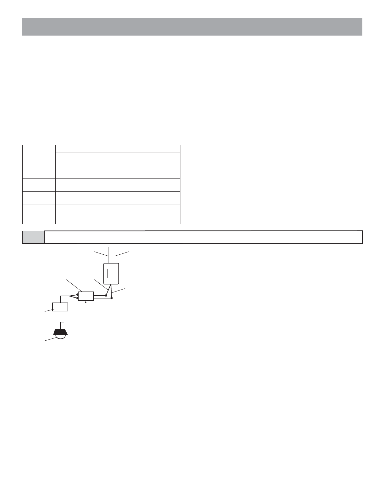
● Emergency alarm
The emergency alarm switch can be connected.
N/C contact (locked type)
DC 12 V/0.1 A or higher
● Call notification
Using the external signaling relay GT-RY allows for the external buzz-
er to be linked during calling.
● Option contact output
External units such as lights can be operated with the option button.
Contact capacity: Maximum overload AC/DC 24 V, 1 A
Minimum overload DC 5 V, 100 mA
● Security/Utility input 1 to 3
Input method
Detection
confirmation
time
Contact
resistance
Terminal short
current
Voltage
between
terminals
N/O or N/C dry closure contact
External sensor input (start signal only detection method)
100 msec or more
N/O: 1 kΩ or less/N/C: 50 kΩ or more
1 mA or less
DC 3.3 V or less (when open between terminals)
● Video out
Video can be output to DVRs etc.
(NTSC, 1 Vp-p/75 Ω) Wiring distance: 3 m
NOTES: When a video signal is output, residential stations may pro-
duce a sound depending on the installation environment.
(The screen playing recorded pictures is not output.)
● Display transfer
External monitors can be activated via the external signaling relay GT-
RY.
● Doctor call (automatic entry)
This makes it possible to use the doctor call (automatic entry) function
at residential stations.
• GT-1C-L/GT-1C, GT-1M-L, GT-1A
Short the DC terminal.
• GT-1D
Cut (open) the jumper JP4.
● Doorbell
The doorbell can be connected.
N/O contact (non-locked type)
DC 12 V/0.1 A or higher
Buzzer
Entrance
light
External signaling relay connection4-6
B
Lead wire (blue)
Lead wire (orange)Timer relay (not included)
AC
Lead wire (white)
GT-RY
Lead wire (orange)
* When the GT-RY is connected, the separate option connecter (4-5) is re-
quired.
GT-RY contact specification: AC/DC 24 V, 0.5 A
- 31 -
Page 32

5
SETTINGS (COMMON AREA)
Setting list5-1
Perform the following settings at an entrance station or security guard station.
Depending on the setting item, some items are set by switching DIP switches and some are set using the program mode menu.
After any DIP switches are switched or any changes are made in the program mode, turn the power supply off and on again. In some
cases, the settings may not be changed.
• The program menu varies according to the unit.
Inst.Setting
= Setting that must be set during installation.
○ = These items can be set according to the installation equipment and application.
GT-DMV/GT-DM
Setting item
GT-NS-V/GT-NS,
GT-DA-L/GT-DA,
GT-VA
2
3
1
D
A
F
B
E
C
5
4
6
M
G
J
I
L
K
H
N
O
8
9
7
W
P
Z
S
T
Q
X
V
U
Y
R
0
GT-MK
Page no.
Entrance station and security guard station ID
setting
Changing the ID code
Writing resident information
Inst.Setting Inst.Setting Inst.Setting
Inst.Setting Inst.Setting Inst.Setting
Inst.Setting Inst.Setting Inst.Setting
Manual setting of residence IDs ○○○36
Setting up the system
Inst.Setting Inst.Setting Inst.Setting
Transferring link information ○○○40
Link check
Inst.Setting Inst.Setting Inst.Setting
Setting the input timeout timer ○○○42
Display language selection
Guidance language selection
Inst.Setting Inst.Setting Inst.Setting
Inst.Setting Inst.Setting
Setting messages and the standby screen ○○ 44
Room number display setting ○○ 45
Scroll speed setting ○○○45
Setting the sort order for searching ○○○46
Access code setting
Inst.Setting Inst.Setting
Entrance monitor setting ○○ 48
Call screen setting ○○ 48
Surveillance camera switching setting ○○ 49
Adjusting screen brightness ○ 49
LCD operation mode setting ○ 50
Security guard station transfer setting ○ 50
Setting prohibition on calls from security guard
stations
○ 50
Entrance zoom picture pre-set ○○ 51
Visibility settings (daytime only) ○○ 52
Entrance night illumination setting ○○ 53
Direct select type light button se
tting ○ 53
34
34
35
37
41
43
43
47
- 32 -
Page 33

Setting method5-2
● Program Mode
Settings can be performed with the GT-NS-V/GT-NS, GT-DMV/GT-DM, and the GT-MK.
Programming cannot be performed from a security guard station if there is a record of an emergency alarm.
1 Check on the display that the unit is in the standby mode.
• When performing the initial settings, "WELCOME" will display at the entrance station and "AIPHONE" will display on the security guard
station GT-MK.
WELCOME
WELCOME
GT-MKGT-NS-V/GT-NS GT-DMV/GT-DM
AIPHONE
2 Press [#], [ ] on the 10 key and enter the 4-digit ID code.
• The initial ID code is "1111".
1 1 1 1
Initial ID code
3 When "RE-ENTER ID CODE" is displayed, re-enter [ ] and the 4-digit ID code.
GT-NS-V/GT-NS GT-DMV/GT-DM
RE-ENTER ID CODE RE-ENTER ID CODE
ENTER ID CODE
RE-ENTER ID CODE
_
GT-MK
1 1 1 1
:CANCEL
4 After entering the program mode, the first setting item displays.
GT-NS-V/GT-NS GT-DMV/GT-DM
SELECT LANGUAGE SELECT LANGUAGE
MENU
SELECT LANGUAGE
GUIDE LANGUAGE
CHANGE ID CODE
:ENTER
GT-MK
Initial ID code
- 33 -
Page 34

Entrance station and security guard station ID setting5-3
IDs for entrance stations and security guard stations are set using the DIP switches of units.
The setting shown with "#1" is the setting at the time of shipment. When installing multiple entrance stations and security guard stations, make sure to
set IDs.
GT-DA-L/GT-DA GT-DMV/GT-DM GT-MK
SW2: 2~4
GT-DMV/GT-DM
SW1: 2~4
ON
1
ON
1
2 3
2 3
#2#1
4
#6#5
4
ON
ON
2
1
A
B
5
4
G
J
I
K
H
8
7
P
S
T
Q
U
#3
ON
2 3
2 3
1
4
#7
ON
1
4
1
1
2 3
2 3
#4
ON
2 3
1
4
4
4
#8
ON
2 3
1
4
R
0
3
D
F
C
E
6
M
L
O
N
9
W
Z
V
X
Y
SW1: 4GT-DA-L/GT-DA
ON
#2#1
ON
2 3
1
1
4
Changing the ID code5-4
Before performing settings, it is recommended that users register an ID code so that other people cannot access the system.
● Enter the program mode with the GT-NS-V/GT-NS, GT-DMV/GT-DM or GT-MK and select "CHANGE ID CODE".
GT-NS-V/GT-NS/GT-MK
CHANGE ID CODE
CHANGE ID CODE
*1111
Current ID code
GT-DMV/GT-DM
MENU
SELECT LANGUAGE
GUIDE LANGUAGE
CHANGE ID CODE
:ENTER
CHANGE ID CODE
ENTER ID CODE
*1111
* + 4 DIGITS
:ENTER
0
2
1
A
B
New ID code
The current ID code is displayed.
Enter the new 4-digit ID code (ex.: 0123) after
3
D
F
C
E
entering [
] on the 10 key.
2 3
4
CHANGE ID CODE
*0123
ID code after change
CHANGE ID CODE
ENTER ID CODE
*0123
Next menu item
* + 4 DIGITS
:ENTER
* If you have forgotten your newly registered ID code, set the switch below to ON for approximately 2 seconds. The ID code will return to the initial
setting of "1111".
GT-NS-V/GT-NS
SW1
1 2 3
ON
4
1
GT-DMV/GT-DM GT-MK
SW2
1 2 3
ON
4
2
1
A
C
B
5
4
G
J
I
L
K
H
8
7
P
S
T
Q
V
U
R
0
4
SW1
1 2 3
3
D
F
E
6
M
O
N
9
W
Z
X
Y
4
ON
1
- 34 -
Page 35

Writing resident information5-5
If the entrance station is a 10 key type or a GT-MK, program the resident information (names and room numbers) before performing the system settings.
Up to 500 resident information entries can be registered.
● Programming with a PC
• You can use a PC to enter data and write in or change resident names.
• In your PC, install the setup tool program from the CD that comes with the GT-BC. A caution scree
• Use the USB cable that comes with the GT-NS-V/GT-NS, GT-DMV/GT-DM, and GT-MK to connect to the PC being used.
* For information on how to use the setup tool, see the text (.txt) file that is installed in the same folder as the setup tool (.exe).
Saving programmed data and resident information data to your PC is recommended.
GT-NS-V/GT-NSGT-DMV/GT-DM GT-MK
Back
n may display, but continue with installation.
2
1
3
A
D
A
B
C
F
C
B
E
4
5
6
M
J
G
K
H
O
L
I
N
7
8
9
P
W
T
S
Z
U
V
X
Q
Y
R
0
● Programming with the GT-NS-V/GT-NS, GT-DMV/GT-DM, or GT-MK.
Enter the program mode and select "RESIDENT INFO." from the menu.
GT-NS-V/GT-NS/GT-MK
RESIDENT INFO.
ROOM #
GT-DMV/GT-DM
MENU
ACCESS CODE
RESIDENT INFO.
SET TIMER
:ENTER
RESIDENT INFO.
ROOM #
MAX 6 DIGITS
:QUIT
:NEXT
0
1 1
Room number
(1 to 6 digits)
USB cable
Enter a room number using 1 to 6 digits.
PC
101
101
SMITH
RESIDENT INFO.
ROOM # 101
_
MAX 32 LETTERS
:QUIT
:ANOTHER NAME
:NEXT
RESIDENT INFO.
ROOM NO. 101
SMITH
MAX 32 LETTERS
:QUIT
:ANOTHER NAME
:NEXT
Register the resident name.
• Resident names can have up to 32 characters.
7
7
P
P
S
Q
Q
R
7
7
P
P
S
R
S
S
Q
Q
R
R
6
M
SM
Resident name (ex. "SMITH")
...
O
N
• Up to 4 names can be registered for one residence (same room number). To register multiple names, press [#] on the 10 key after entering a name and enter t
• Press [
resident name.
Next menu item
- 35 -
he next name.
] to delete the room number and
Page 36

Manual setting of residence IDs5-6
Residential station IDs are automatically assigned during link setting. However, with the GT-2C-L/GT-2C and GT-1C-L/GT-1C units only, they can be
set manually using the switches on the unit. All are set to OFF in the initial settings.
When replacing a residential station due to malfunction, resetting the link is unnecessary as the link can be maintained by adjusting the switches.
1
GT-2C-L
GT-2C
GT-1C-L
GT-1C
Residence ID automatic setting:
"0000 0000"
SW2
ON
2 345 6 7
1
8
Change the decimal notation IDs to binary IDs to set the resi-
dence IDs.
• 1 indicates (ON) and 0 indicates (OFF).
• For the binary notation, refer to the appendix information about the
setup tool and perform settings as shown below.
GT-NS-V/GT-NS
USB cable
PC
GT-DMV/GT-DM GT-MK
Back
2
1
3
A
D
A
B
C
F
C
B
E
4
5
6
M
J
G
K
H
O
L
I
N
7
8
9
P
W
T
S
Z
U
V
X
Q
Y
R
0
2 Create a correlation table with the setup tool between the IDs
set for residences and the resident names and export this to the
entrance station or security guard station.
* For information on how to use the setup tool, see the text (.txt) file that
is installed in the same folder as the setup tool (.exe).
Saving programmed data and resident information data to your PC is
recommended.
Setting up the system5-7
System settings can be performed from an entrance station or security guard station.
1
2
3
4
48
250
Binary notationDecimal notation
00000001
00000010
00000011
00000100
00110000
11111010
DIP switch
If residential stations are mixed, be sure to perform [5-7 Setting up the system] after [5-6 Manual setting of residence IDs]. If a sequence
mistake is made, IDs may be duplicated and operation may not occur.
- 36 -
Page 37

● Performing settings from an entrance station
1
1 Check that all units are mounted and wired correctly, and then
turn on the power switch of the GT-BC.
ON
ON
GT-BC
OFF
2
GT-DMV/GT-DM
2 With the GT-DA/GT-DA-L, loosen the base screw of the frame
and open and remove the front panel.
Remove the rubber cap and use a fine screwdriver to push the program
switch.
With the GT-DMV/GT-DM, enter the program mode and select
"PROGRAMMING" from the menu.
Wait until "CONNECTING..." is displayed.
The in use LED will blink for approximately 6 to 15 seconds.
MENU
CHANGE GREETING
PROGRAMMING
GT-DA-L/GT-DA
TRANSFER DATA
:ENTER
PROGRAMMING
CONNECTING...
3 Once the in use LED is lit solid, press and hold down the door
:QUIT :PRESET
3
release button while holding down the security guard station
call/light button of the residential station.
A beep will sound approximately 5 seconds later and all of the residence IDs will be initialized.
5
GT-SW
CAUTION: Performing the above operation will delete all link data in the resi-
4
4 Check that the in use LED is lit, and press the TALK button of
dential station and return it to the initial settings. Only perform this
operation when performing settings the first time after mounting a
residential station. When changing settings, skip this procedure.
the first residential station. With the handset type module, lift
the handset.
The corresponding communication channel will be established.
5 GT-SW: Press the relevant call button. (Do not press the button
Beep
GT-NS-V/GT-NS
101
SMITH
GT-DMV/GT-DM
Beep
Beep
101
SMITH
longer than 1 second.)
GT-NS-V/GT-NS, GT-DMV/GT-DM: Display the assigned room no.
and press the button. (Do not press the button longer than 1 second.)
An electronic beep will be emitted once. Link setting can be performed for up to 4 stations. (With registration, the electronic beep will
sound a number of times equal to the number of connected stations.)
- 37 -
Page 38

6
6 Press the OFF button to finish programming. With the handset
type module, return the handset. Repeat steps 3 to 6 to program
all residential stations.
7
GT-DA-L/GT-DA
* Erasing links
5
GT-SW
Beep
GT-DMV/GT-DM
PROGRAMMING
CONNECTING...
:QUIT :PRESET
GT-NS-V/GT-NS
101
SMITH
GT-DMV/GT-DM
Next menu item
101
SMITH
Beep
7 Press the program switch of the GT-DA-L/GT-DA to finish
programming.
The in use LED will go out.
For the GT-DMV/GT-DM, press the button.
After step 5, press and hold the
sounds.
A beep will sound and the link to the corresponding residential station
will be erased.
button until the confirmation tone
Beep
- 38 -
Page 39

● Performing settings from a security guard station
1
ON
GT-BC
ON
OFF
GT-MK
2
PROGRAMMING <<
2
3
1
D
A
F
C
B
E
5
4
6
M
G
J
I
L
O
K
H
N
8
9
7
W
P
Z
S
T
Q
V
X
U
Y
R
0
PROGRAMMING <<
CONNECTING...
1 Check that all units are mounted and wired correctly, and then
turn on the power switch of the GT-BC.
2 Enter the program mode at the GT-MK and select "PRO-
GRAMMING" from the menu. Wait until "CONNECTING..."
is displayed.
3
1
2
A
B
C
3
4
D
G
E
H
I
F
5
J
K
L
P
6
7
M
Q
N
S
R
O
8
T
U
V
W
9
X
Z
Y
0
4
3 Lift the handset of the GT-MK.
4 Press and hold down the door release button while holding down
the security guard station call/light button of the residential station.
A beep will sound approximately 5 seconds later and all of the residence IDs will be initialized.
CAUTION: Performing the above operation will delete all link data in the resi-
5
5 Press the talk button on the first residential station.
dential station and return it to the initial settings. Only perform this
operation when performing settings the first time after mounting a
residential station. When changing settings, skip this procedure.
With the handset type module, lift the handset.
The corresponding communication channel will be established.
6
101
SMITH
Beep
1
2
A
B
C
3
4
D
G
E
H
I
F
5
J
K
L
P
6
7
M
Q
N
S
R
O
8
T
U
V
W
9
X
Z
Y
0
6 Display the assigned room no. and press the button. (Do not
press the button longer than 1 second.)
An electronic beep will be emitted once.
Link setting can be performed for up to 4 stations. (With registration,
the electronic beep will sound a number of times equal to the number
of connected stations.)
8
PROGRAMMING <<
CONNECTING...
* Erasing links
7
1
2
A
B
C
3
4
D
G
E
H
I
F
5
J
K
L
P
6
7
M
Q
N
S
R
O
8
T
U
V
W
9
X
Z
Y
0
Next menu item
101
SMITH
7 Return the handset of the GT-MK. Repeat steps 4 to 6 to pro-
gram all residential stations.
8 Press the button to finish programming.
After step 6, press and hold the button until the confirmation tone
sounds.
A beep will sound and the link to the corresponding residential station
1
2
A
B
C
3
4
D
G
E
H
I
F
5
J
K
L
P
6
7
M
Q
N
S
R
O
8
T
U
V
W
9
X
Z
Y
0
will be erased.
- 39 -
Page 40
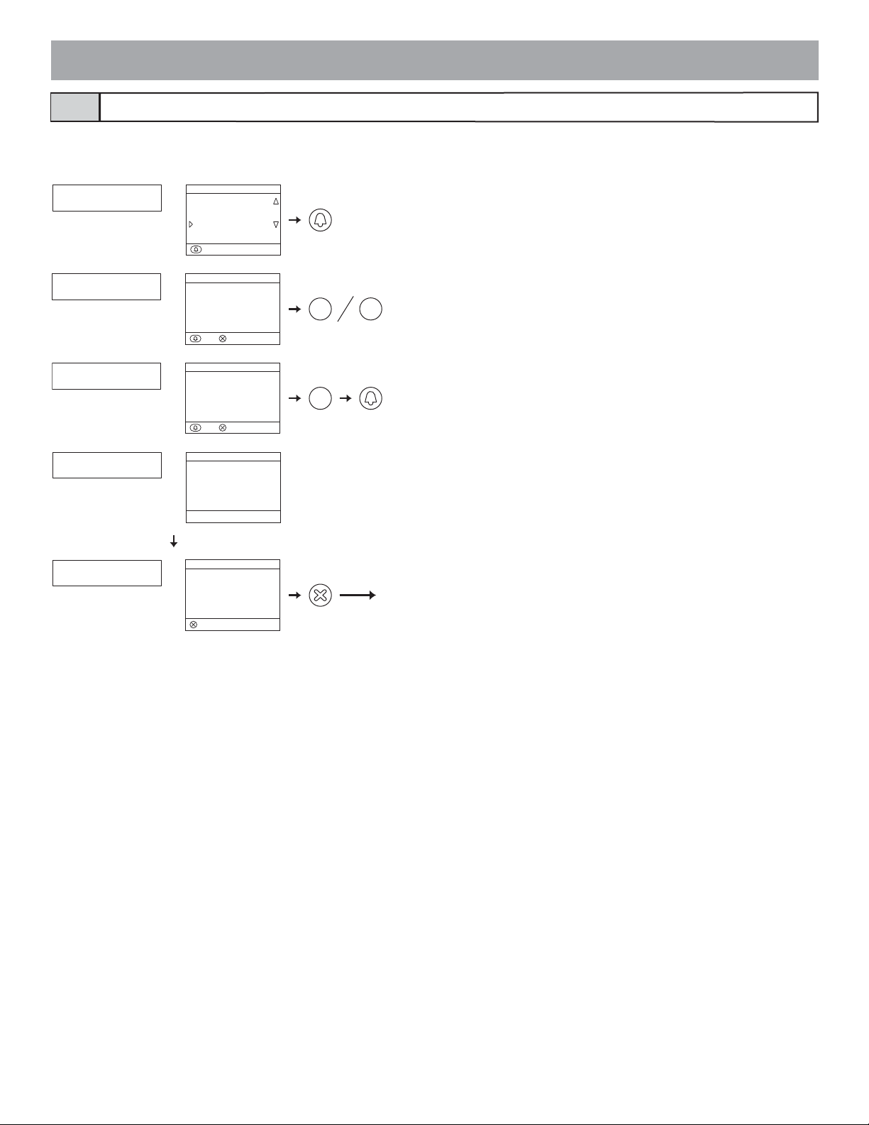
Transferring link information5-8
Transfer link setting information set at an entrance station or security guard station to other entrance stations and security guard stations.
● Enter the program mode and select "TRANSFER DATA".
GT-DMV/GT-DMGT-NS-V/GT-NS, GT-MK
TRANSFER DATA
MENU
CHANGE GREETING
PROGRAMMING
TRANSFER DATA
:ENTER
ENTER UNIT ID#
MAIN ENTRANCE: 2
ENTER UNIT ID#
SECURITY GUARD: 2
TRANSFERRING.
DATA TRANSFERRED
TRANSFER DATA
ENTER UNIT ID#
MAIN ENTRANCE: 2
“0” FOR GUARD
:QUIT
:ENTER
TRANSFER DATA
ENTER UNIT ID#
SECURITY GUARD: 2
:QUIT
:ENTER
TRANSFER DATA
TRANSFERRING...
TRANSFER DATA
DATA TRANSFERRED
:QUIT
0
1
1~4
1
1~16
Next menu item
Enter an entrance station number (1 to 16) for the transferred station. If
"0" is entered, a security guard station will be the transferred station.
With an expanded system, the entrance stations IDs are as shown below.
• Connected to same common line: ID remains the same (Ex.: Enter "2"
to transfer to #2)
• Connected to separate common line: ID + 8 (Ex.: Enter "9" to transfer
to #1)
Enter a security guard station number (1 to 4) for the transferred station.
With an expanded system, the security guard station IDs are as shown
below.
• Connected to same common line: ID remains the same (Ex.: Enter "2"
to transfer to #2)
• Connected to separate common line: ID + 2 (Ex.: Enter "3" to transfer
to #1)
During transfer, "TRANSFERRING..." is displayed.
- 40 -
Page 41

Link check5-9
● Performing settings from an entrance station (Unit type)
Press the program switch of the GT-DA-L/GT-DA for at least 5 seconds.
The in use LED will light up after blinking.
GT-SW: Press the relevant call button.
GT-NS-V/GT-NS: Select the room and press the
button.
GT-DA-L/GT-DA
is abnormal, an error sound will be emitted.
● Performing settings from an entrance station (Integrated type), security guard station
An electronic sound will be emitted once if the link is normal. If the link
MENU
VERIFY PROGRAM
SCROLL SPEED
MONITOR ENTRANCE
:ENTER
VERIFY PROGRAM
VERIFYING...
:QUIT
GT-MKGT-DMV/GT-DM
VERIFY PROGRAM
VERIFYING...
Next menu item
Enter the program mode and select "VERIFY PROGRAM".
Select the room and press the
VERIFY PROGRAM
ROOM NO. 101
SMITH
101
SMITH
With a security guard station, an electronic sound will be emitted once if
the link is normal. If the link is abnormal, an error sound will be emitted.
With an entrance station (Integrated type), "CORRECT" will display if
:VERIFY
:QUIT
the link is normal and "ERROR" will display if it is not normal.
button.
- 41 -
GT-DMV/GT-DM GT-DMV/GT-DM
VERIFY PROGRAM
CORRECT
:QUIT
VERIFY PROGRAM
ERROR
:QUIT
Page 42

Setting the input timeout timer5-10
● Enter the program mode with the GT-NS-V/GT-NS, GT-DMV/GT-DM or GT-MK and select "SET TIMER".
• Operation timer: If the operation panel is not operated for a certain period of time, the system returns to standby mode. The initial setting is 15
seconds.
• Program timer: If an operation is not performed for a certain period of time in the program mode, the program mode will automatically be can-
celled. The initial setting is 60 seconds.
• Call timer: Calls from entrance stations and security guard stations will expire after a certain period of time. The initial setting is 45 seconds.
• Door release timer: Set the time for when the door is locked again after a door release operation. The initial setting is 0 seconds.
GT-DMV/GT-DMGT-NS-V/GT-NS, GT-MK
SET TIMER
MENU
ACCESS CODE
RESIDENT INFO.
SET TIMER
:ENTER
OPERATION TIMER
15
PROGRAM TIMER
60
CALL DURATION
45
SET TIMER
OPERATION TIMER
15 s
INPUT 15-99
:QUIT
:NEXT
SET TIMER
3
D
E
15~99
0
F
PROGRAM TIMER
60 s
INPUT 30-99
:QUIT:NEXT
SET TIMER
W
X
9
Z
Y
30~99
0
CALL DURATION
45 s
INPUT 30-99
:QUIT
:NEXT
6
M
N
30~99
0
O
* Entrance stations (Integrated type) only
SET TIMER
RELEASE TIMER
15 s
INPUT 00-20
00=WHILE PRESSED
:QUIT
:NEXT
2
A
B
00~20
0
C
Set the operation timer in the range from 15 to 99 seconds.
Set the program timer in the range from 30 to 99 seconds.
Set the call timer in the range from 30 to 99 seconds.
Set the door release timer in the range from 00 to 20 seconds.
If the timer is set at 00 seconds, the door will be released only
while the button is pressed.
Next menu item
● Entrance station (Unit type) door release timer: Set the GT-DA-L/GT-DA
GT-DA-L/GT-DA
20
0.5 M
103
0.5 to 20: 0.5 to 20 seconds
M: While door release button is pressed
- 42 -
with volume VR1.
Page 43
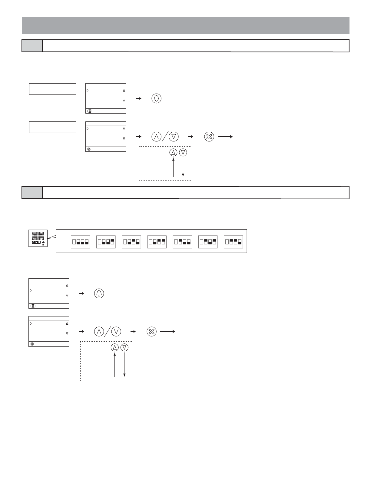
5-11
Display language selection
● Start the program mode with the GT-NS-V/GT-NS, GT-DMV/GT-DM or GT-MK and select "SELECT LANGUAGE".
The initial setting is English.
Select English, French, German, Spanish, Dutch, or Italian.
GT-DMV/GT-DMGT-NS-V/GT-NS, GT-MK
SELECT LANGUAGE
MENU
SELECT LANGUAGE
GUIDE LANGUAGE
CHANGE ID CODE
:ENTER
SELECT LANGUAGE
ENGLISH
SELECT LANGUAGE
ENGLISH
FRANÇAIS
DEUTSCH
:ENTER
Next menu item
ENGLISH
FRANÇAIS
DEUTSCH
ESPAÑOL
NEDERLANDS
ITALIANO
5-12
Guidance language selection
Select the guidance language that will be heard when a call is received, etc. The initial setting is for no guidance.
● GT-DA-L: Perform settings using combinations of 2 to 4 with SW3.
Select English, French,
GT-DA-L
SW3
German, Spanish, Dutch, Italian or no guidance.
No guidance English French German Spanish Dutch Italian
ON
2 3
1
ON
2 3
1
4
ON
2 3
1
4
ON
2 3
1
4
ON
2 3
1
4
ON
2 3
1
4
ON
2 3
1
4
4
● GT-DMV/GT-DM: Start the program mode and select "GUIDE LANGUAGE".
Select English, French, German, Spanish, Dutch, Italian or no guidance.
GT-DMV/GT-DM
MENU
SELECT LANGUAGE
GUIDE LANGUAGE
CHANGE ID CODE
:ENTER
GUIDE LANGUAGE
NO GUIDANCE
ENGLISH
FRANÇAIS
:ENTER
Next menu item
NO GUIDANCE
ENGLISH
FRANÇAIS
DEUTSCH
ESPAÑOL
NEDERLANDS
ITALIANO
- 43 -
Page 44

Setting messages and the standby screen5-13
● GT-NS-V/GT-NS: Use 3 of SW1 to change the greeting message to an operation message. The initial setting is for a greeting message.
GT-NS-V/GT-NS
● GT-DMV/GT-DM: Start the program mode and select "STANDBY SCREEN".
GT-DMV/GT-DM
MENU
STANDBY SCREEN
BRIGHTNESS
SORT SETTING
:ENTER
SW1
ON
2 3
1
Operation message
Greeting message
3
4
STANDBY SCREEN
GREETING
OPERATION
PICTURE
:ENTER
Select from the following in the standby screen display.
• Greeting message
• Operation message
• Picture
* Changing the greeting message
GT-NS-V/GT-NS, GT-DMV/GT-DM: Start the program mode and select "CHANGE GREETING".
Greetings can have up to 160 characters.
Press [
] to delete the greeting message.
GT-NS-V/GT-NS GT-DMV/GT-DM
CHANGE GREETING
CHANGE GREETING
WELCOME
CHANGE GREETING
WELCOME TO ...
MENU
CHANGE GREETING
PROGRAMMING
TRANSFER DATA
:ENTER
CHANGE GREETING
WELCOME
MAX 160 LETTERS
:ENTER
CHANGE GREETING
WELCOME TO ...
MAX 160 LETTERS
:ENTER
9
W
X
3
Z
Y
3
D
D
F
E
E
......
F
EW
Ex.: "WELCOME TO..."
Next menu item
* Uploading an picture
For details, see the text (.txt) file that is installed in the same folder as the setup tool (.exe).
- 44 -
Page 45
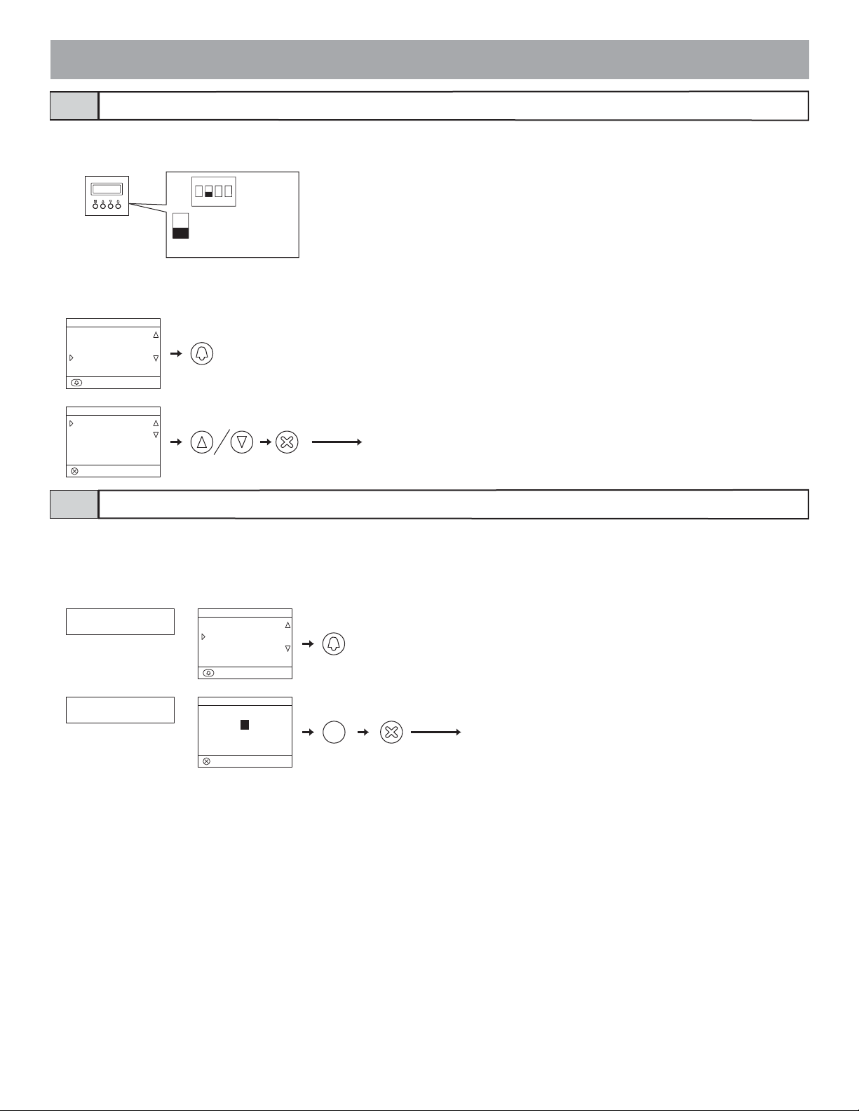
5-14
Room number display setting
Set the entrance station display to show room numbers or to display only resident names. The initial setting is for the room number to also display.
● GT-NS-V/GT-NS: Switch this setting with 2 of SW1.
GT-NS-V/GT-NS
SW1
ON
2 3
1
4
Display only resident name
Display room number also
2
● GT-DMV/GT-DM: Enter the program mode and select "DISPLAY ROOM NO.". Select ON (room number also displays) or OFF (only resident
name displays).
GT-DMV/GT-DM
MENU
CALL-IN DISPLAY
LIGHT OR CCTV
DISPLAY ROOM NO.
:ENTER
DISPLAY ROOM NO.
OFF
ON
:ENTER
Next menu item
5-15
Scroll speed setting
The scroll speed for messages and resident names (17 characters or more) that display on entrance station and security guard station displays can be
changed. The initial setting is "5".
● GT-NS-V/GT-NS
, GT-DMV/GT-DM, GT-MK: Enter the program mode and select "SCROLL SPEED".
Set a digit from 0 to 9. 0 = Slow 9 = Fast.
GT-NS-V/GT-NS/GT-MK
SCROLL SPEED
SCROLL SPEED
5
GT-DMV/GT-DM
MENU
VERIFY PROGRAM
SCROLL SPEED
MONITOR ENTRANCE
:ENTER
SCROLL SPEED
5
SLOW 0----9 FAST
:ENTER
7
P
S
Q
R
0-9
Next menu item
- 45 -
Page 46

Setting the sort order for searching5-16
Select either name order or room number order for searching at entrance stations and security guard stations. The initial setting is name order.
● GT-NS-V/GT-NS, GT-DMV/GT-DM, GT-MK: Enter the program mode and select "SORT SETTING".
GT-NS-V/GT-NS/GT-MK
SORT SETTING
GT-DMV/GT-DM
MENU
STANDBY SCREEN
BRIGHTNESS
SORT SETTING
:ENTER
SORT SETTING
SORT BY NAME
SORT SETTING
SORT BY NAME
SORT BY ROOM NO.
:ENTER
Next menu itemCurrent search order
- 46 -
Page 47

Access code setting5-17
Up to 500 access codes can be set for door release at an entrance station.
The number of digits for access codes can be set anywhere in the range from 4 to 6. The initial setting is 4 digits.
* Setting the access code number of digits
GT-NS-V/GT-NS, GT-DMV/GT-DM: Enter the program mode and select "ACCESS CODE".
GT-NS-V/GT-NS GT-DMV/GT-DM
ACCESS CODE
MENU
ACCESS CODE
RESIDENT INFO.
SET TIMER
:ENTER
ACCESS CODE
NO. OF DIGIT : 4
Current digit
ACCESS CODE : 001
ACCESS CODE : 001
1111
Current access code
ACCESS CODE : 002
ACCESS CODE
NO. OF DIGIT 4
INPUT 4-6
:ENTER:NEXT
ACCESS CODE
ACCESS CODE 001
INPUT 001-500
:QUIT
:NEXT
ACCESS CODE
ACCESS CODE 001
_
1111
:ENTER
:NEXT
ACCESS CODE
ACCESS CODE 002
:ENTER
:NEXT
6
M
O
N
4-6
0 9
W
Z
X
Y
1 1 1 1 1 1
Access code 001
Next menu item
Set the number of digits in the range from 4 to 6.
Select the access code to set from "001" to "500".
Enter the number directly using the number keys or select it
by using the
and buttons.
Enter the access code.
* Codes with more digits than the set number of digits for
access codes cannot be entered.
- 47 -
Page 48

5-18
Entrance monitor setting
Monitoring with the entrance station camera from a residential station can be set to be possible or not possible. The initial setting makes this not possible.
● GT-DA-L/GT-DA: Switch this setting with 1 of SW2.
GT-DA-L/GT-DA
SW2
ON
2 3
1
Monitoring possible
Monitoring not possible
4
1
● GT-DMV/GT-DM: Enter the program mode and select "MONITOR ENTRANCE".
GT-DMV/GT-DM
MENU
VERIFY PROGRAM
SCROLL SPEED
MONITOR ENTRANCE
:ENTER
MONITOR ENTRANCE
OFF
ON
:ENTER
Next menu item
5-19
Call screen setting
Screen switching during a call can be set to "ZOOM", "WIDE", "ZOOM 3s >> WIDE", or "WIDE 3s >> ZOOM". The initial setting is "ZOOM".
● GT-VA: Switch this setting with 3 and 4 of SW1.
GT-VA
● GT-DMV/
GT-DMV/GT-DM
MENU
CALL-IN DISPLAY
LIGHT OR CCTV
DISPLAY ROOM NO.
:ENTER
CALL-IN DISPLAY
ZOOM
WIDE
ZOOM 3s >> WIDE
:ENTER
GT-DM: Enter the program mode and select "CALL-IN DISPLAY".
SW1
ON
1
ZOOM
2 3
WIDE
ON
2 3
1
4
4
ZOOM3s>>WIDE
ON
2 3
1
4
WIDE3s>>ZOOM
ON
2 3
1
4
Next menu item
- 48 -
Page 49

5-20
Surveillance camera switching setting
Select "LIGHT CONTROL" or "CCTV SWITCH" for the operation performed when the light button on a residential station is pressed. The initial setting is OFF ("LIGHT CONTROL").
● GT-VA: Switch this setting with 2 of SW1.
SW1
GT-VA
ON
2 3
1
4
Surveillance camera
switching
Light control
2
● GT-DMV/GT-DM: Enter the program mode and select "LIGHT OR CCTV". Select using the
GT-DMV/GT-DM
MENU
CALL-IN DISPLAY
LIGHT OR CCTV
DISPLAY ROOM NO.
:ENTER
LIGHT OR CCTV
LIGHT CONTROL
CCTV SWITCH
:ENTER
5-21
Adjusting screen brightness
Next menu item
and buttons.
Screen brightness can only be adjusted with the GT-DMV/GT-DM.
● Start the program mode and select "BRIGHTNESS". Set a digit from 0 to 9. 0 = Dark 9 = Bright. The initial setting is "6"
GT-DMV/GT-DM
MENU
STANDBY SCREEN
BRIGHTNESS
SORT SETTING
:ENTER
BRIGHTNESS
4
DARK 0----9 BRIGHT
:ENTER
0 9
W
Z
X
Y
Next menu item
.
- 49 -
Page 50

LCD operation mode setting5-22
The LCD screen automatic ON function can only be set with the GT-DMV/GT-DM. The initial setting is sensor mode.
• Sensor mode: The LCD will automatically turn ON due to the sensor when a person approaches. The detection distance changes depending on the
direction that the person approaching is facing.
• Energy saving mode: Detection is not performed by the sensor. When a button is operated, the LCD turns ON.
Do not place objects such as plants or trees in places monitored by the sensor. Also, placing the unit in very bright sunlit areas may prevent the sen-
sor from working properly.
● Switch this setting with 2 and 3 of SW1.
GT-DMV/GT-DM
5-23
Security guard station transfer setting
Sensor mode
SW2
ON
2 3
1
Energy saving mode
ON
2 3
1
170 cm tall person is detected at
approximately 1 to 3 meters
4
4
Sensor
Adjust the detection distance with the sensor control switch on the back. When
the switch is in the center, a person 170 cm tall is detected at approximately 1
to 3 meters. If the switch is pressed up, people are detected in a longer range. If
the switch is pressed down, people are detected in a short
adjust the setting in accordance with the installation environment.
Short
range
H
L
H
L
er range. Be sure to
H
L
Long
range
Perform settings for whether calls to security guard stations and emergency alarms are transferred from the RY-RY terminal. The initial settings are for
calls and alarms to be transferred.
● GT-MK: Enter the program mode and select "OPTIONAL OUTPUT".
GT-MK
OPTIONAL OUTPUT
OPTIONAL OUTPUT
CALL OFF
Current setting
OPTIONAL OUTPUT
ALARM ON
Current setting
Select whether calls are transferred or not transferred.
Select whether emergency alarms are transferred or not transferred.
OPTIONAL OUTPUT
CALL ON
5-24
Security guard stations can
Setting prohibition on calls from security guard stations
be set only to receive calls. The initial setting allows outgoing calls.
● GT-MK: Switch this setting with 3 of SW1.
GT-MK
2
1
A
C
B
5
4
G
J
I
L
K
H
8
7
P
S
T
Q
V
U
R
0
3
D
F
E
6
M
O
N
9
W
Z
X
Y
SW1
3
ON
2 3
1
Calling
prohibited
Calling
allowed
Next menu item
4
- 50 -
Page 51

Entrance zoom picture pre-set5-25
The picture can be set to display at the position set for zoom picture display when a residential station is called from an entrance station. The initial setting is for display at the center.
Perform this setting in the pre-set mode.
In the case of direct select type entrance stations and residential stations without a ZOOM/WIDE function, this pre-set is not possible.
Setting using an entrance station 10 key
Entrance Station (Unit type)
● Start the pre-set mode
1 Loosen the base screw of the frame and open and remove the
front panel.
2 Remove the rubber cap and use a fine screwdriver to push the
program switch.
The in use LED will stay lit after blinking for approximately
6 to 15 seconds.
3 Press the [#] button on the GT-10K.
GT-DA-L/GT-DA
GT-DA-L/GT-DA
Entrance Station (Integrated type)
● Start the pre-set mode
1 Enter the program mode and select "PROGRAMMING".
2 After the in use LED lights up, press [#] on the 10 key.
GT-DMV/GT-DM
MENU
CHANGE GREETING
PROGRAMMING
TRANSFER DATA
:ENTER
PROGRAMMING
CONNECTING...
:QUIT :PRESET
● Perform the pre-set settings
Enter the pre-set position using [1] to [9] on the 10 key.
• At this time, the pictu
or lifting the handset on the residential station.
re can be checked by pressing the talk button
● Perform the pre-set settings
Enter the pre-set position using [1] to [9] on the 10 key.
• At this time, the picture can be checked by pressing the talk button
or lifting the handset on the residential station.
GT-NS-V/GT-NS
CAMERA PRESET: 5
CONNECTING...
3
6
97
9
W
1
Z
X
Y
12
45
8
GT-DMV/GT-DM
CAMERA PRESET
CONNECTING...
5
ZOOM BY NO. 1-9
:ENTER
9
W
1
3
6
97
Z
X
Y
12
45
8
- 51 -
Page 52

● Quit the pre-set mode
1 Press the button to register the pre-set position.
2 Press the program switch of the GT-DA-L/GT-DA to finish
programming.
GT-NS-V/GT-NS
CAMERA PRESET: 5
CONNECTING...
GT-DA-L/GT-DA
CONNECTING...
● Quit the pre-set mode
1 Press the button to register the pre-set position.
2 Press the button to return to the menu.
GT-DMV/GT-DM
CAMERA PRESET
CONNECTING...
5
ZOOM BY NO. 1-9
:ENTER
PROGRAMMING
CONNECTING...
:QUIT :PRESET
Setting using a residential station (limited to stations with a zoom/wide function)
The picture can be set to display using a set zoom picture position for when a call is received from an entrance station.
When switching from the wide screen to the zoom screen, the zoom screen displays starting from the pre-set position.
1 Enter the pre-set mode from an entrance station.
2 Start communication from a residential station to display the picture at the currently set pre-set zoom position.
3 Adjust the camera zoom position using the [S], [T], [W], and [X] buttons on the residential station.
4 Press the [ ZOOM/WIDE] button (for at least 2 seconds). A beep will sound and the position setting will be completed.
5 End residential station communication.
6 Exit the pre-set mode from the entrance station.
* Setting can be performed in the same manner even if the entrance station is in programming mode.
* Pressing the entrance station call button will set a link with a residence, but pre-set settings cannot be performed.
* The position set at one entrance station will be displayed at all linked residential stations.
NOTES:
1. To change the zoom screen position that has been set, perform the zoom screen settings again.
The previous settings will be overwritten.
2. The set zoom screen position will also be displayed at the sub master monitor station.
* Pre-sets cannot be set from a sub master monitor station.
Visibility settings (daytime only)5-26
When entrance station is installed at a location where backlighting makes viewing difficult, settings can be performed for easier viewing.
1 Enter the pre-set mode from an entrance station.
2 Start communication from a residential station to display the picture at the currently set pre-set zoom position.
3 Press the [ ADJUST] button to adjust the daytime brightness.
4 Press the [ ADJUST] button (for at least 2 seconds). A beep will sound and the setting will be completed.
5 End residential station communication.
6 Exit the program mode from the entrance station.
- 52 -
Page 53

5-27
Entrance night illumination setting
At night, the illuminator LED automatically lights up during an entrance station call. It can be set to always be off if night illumination is unnecessary
or it is too bright.
The initial setting is for the LED to automatically light up.
● GT-VA, GT-DMV/GT-DM: Switch this setting with 1 of SW1.
GT-VA
SW1
ON
2 3
1
4
Always off Always off
Automatically
lights up
1
GT-DMV/GT-DM
SW1
Automatically
lights up
1
ON
2 3
1
4
5-28
Direct select type light button setting
One of the call buttons on the GT-SW can be set as the light button.
1 Loosen the base screw of the speech module and open and remove the front panel.
2 Remove the rubber cap and use a fine screwdriver to push the setting switch.
The in use LED will blinks.
3 While the in use LED is blinking (approximately 15 seconds), press the call button to assign it as the light button. An electronic
beep will be emitted once.
* A button cannot be simultaneously used as a residence call button and a light button.
12 3
GT-DA-L/GT-DA
GT-DA-L/GT-DA
Press the call button assigned as the light button to light up the light connected to the entrance.
Beep
GT-SW
- 53 -
Page 54

6
Setting (GT-2C-L/GT-2C)
1. See the operation manual included with the GT-2C-L/GT-2C for the name and operating method for each part.
2. Actual screens may vary depending on the system.
3. When settings are changed, turn the unit power supply off and on again. In some cases, the settings may not be changed.
6-1
1 In the standby mode, press the [ ADJUST] button and [
How to use the MENU
ZOOM/WIDE] button until the warning screen displays. Press
the [ MENU] button in accordance with the warning screen.
MOVE ON TO INSTALLATION SETTING?
CHANGING SOME SETTING MAY CAUSE
MALFUNCTION.
CANCEL OK
2 Press the [S], [T], [W], and [X] buttons in the "INSTALLA-
TION" screen to select the item to be set and confirmed, and
press the [
3 To finish changing settings, press the [ OFF] button to return
to the standby mode. In other cases, set by pressing the [
MENU] button. Press the [
the settings and return to the previous screen.
6-2
Change the names of the security guard stations that display with the GT-2C-L/GT-2C.
Security guard station settings
MENU] button.
INSTALLATION
ALARM INPUT PRESS TO TALK
EXTERNAL INPUT INITIALIZE
GUARD SETTING DOCTOR CALL
REC/PLAY] button to cancel
1 After performing steps 1 in section 6-1, select "GUARD SET-
TING" in the "INSTALLATION" screen and press the [
MENU] button.
2 In the "GUARD SETTING" screen, make a selection from
"GUARD1" to "GUARD4" and press the [ MENU] button.
Select from "GUARD/CONCIERGE/RECEPTION/NOT DISPLAYED" for each. Press the [ MENU] button to complete the
settings.
GUARD SETTING
GUARD1 [ GUARD1 ]
GUARD2 [ RECEPTION2 ]
GUARD3 [ CONCIERGE3 ]
GUARD4 [ NOT DISPLAYED ]
- 54 -
Page 55

6-3
Emergency input settings
Set emergency input to be enabled or disabled.
1 After performing steps 1 in section 6-1, select "ALARM IN-
PUT" in the "INSTALLATION" screen and press the [
MENU] button.
6-4
Set external input (3 circuits) to security sensor or utility sensor.
External input setting
1 After performing steps 1 in section 6-1, select "EXTERNAL
INPUT" in the "INSTALLATION" screen and press the [
MENU] button.
2 In the "EXTERNAL INPUT SETTING" screen, make a selec-
tion from "SENSOR1" to "SENSOR3" and press the [
MENU] button.
EXTERNAL INPUT SETTING
SENSOR 1
SENSOR 2
SENSOR 3
2 Select "DISABLE", "N/O", or "N/C" in the "ALARM INPUT"
screen. Press the [ MENU] button to complete the settings
and return to the previous screen.
ALARM INPUT
DISABLE
N/O
N/C
3 Select from "DISABLE/UTILITY/SECURITY" in each screen
from "SENSOR1 SETTING" to "SENSOR3 SETTING" and
then press the [ MENU] button.
SENSOR1 SETTING
DISABLE
UTILITY
SECURITY
- 55 -
Page 56

Utility sensor setting (detection method)
4 When "UTILITY" is selected, select "N/O" or "N/C" in the
"UTILITY-SENSOR DETECTION METHOD" screen and
press the [
MENU] button.
Security sensor (alarm transfer)
5 When [SECURITY] is selected, in the [EXTERNAL INPUT
SETTING] screen, select [ALARM TRANSFER] and press
MENU] button.
the [
UTILITY-SENSOR DETECTION METHOD
N/O
N/C
Security sensor setting (detection method)
4 When "SECURITY" is selected, select "N/O" or "N/C" in the
"SECURITY-SENSOR DETECTION METHOD" screen and
press the [
MENU] button.
SECURITY-SENSOR DETECTION METHOD
N/O
N/C
EXTERNAL INPUT SETTING
SENSOR 1
SENSOR 2
SENSOR 3
ALARM TRANSFER
6 Select from "ENABLE/DISABLE" in the "SECURITY ALARM
TRANSFER" screen. Press the [ MENU] button to complete
the settings.
SECURITY ALARM TRANSFER
ENABLE
DISABLE
NO TRANSFER FOR UTILITY ALARM
- 56 -
Page 57

6-5
Set Doctor call to be enabled or disabled.
Doctor call setting
1 After performing steps 1 in section 6-1, select "DOCTOR
CALL" in the "INSTALLATION" screen and press the [
MENU] button.
6-6
Set press-to-talk during communication to be enabled or disabled.
Press-to-talk setting
1 After performing steps 1 in section 6-1, select "PRESS TO
TALK" in the "INSTALLATION" screen and press the [
MENU] button.
2 Select from "ENABLE/DISABLE" in the "DOCTOR CALL"
screen. Press the [ MENU] button to complete the settings.
DOCTOR CALL
ENABLE
DISABLE
2 Select from "ENABLE/DISABLE" in the "PRESS TO TALK"
screen. Press the [
MENU] button to complete the settings.
PRESS TO TALK
ENABLE
DISABLE
- 57 -
Page 58
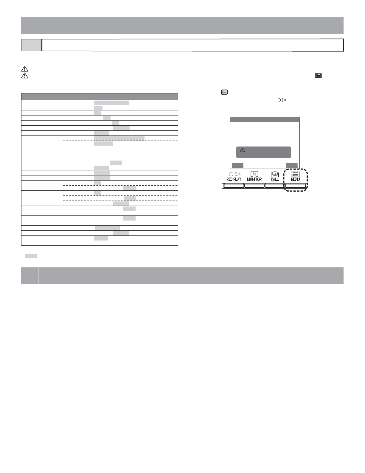
Initializing6-7
All settings can be restored to their condition at the time of purchase.
1. Recorded pictures are erased and settings are reset.
2. Pre-set functions are not reset.
Settings reset with "Restor default setting"
DATE/TIME JAN/01/2011 00 : 00
LANGUAGE ENG FRA DEU ITA NED ESP
ENTRANCE CALL TONE
DOOR CALL TONE
GUARD CALL TONE ♪1 •♪2 • ♪3 •♪4 •♪5
DOCTOR CALL
PRESS TO TALK
PICTURE MEMORY Pictures
CALL DURATION
NIGHT ILLUMINATION
ALARM INPUT
EXTERNAL INPUT (S1 to S3)
UTILITY-SENSOR Detection N/O • N/C
SECURITY-SENSOR Detection
DEPARTURE TIMER SETTING
ARRIVAL TIMER SETTING 0 sec. • 30 sec. • 60 sec. • 120 sec. • 300 sec. •
SECURITY PIN
RESET SETTING
GUARD (GUARD 1 to 4)
Setting name Description
♪1 • ♪2 •♪3 •♪4 •♪5
♪1 • ♪2 •♪3 •♪4 •♪5
ENABLE DISABLE
ENABLE DISABLE
Screen
Alarm timer
Alarm timer
Alarm Transfer
All saved pictures are erased.
• Zoom X 6
• Wide X 6
• Zoom X 3, Wide X 3
• Wide X 3, Zoom X 3
30 sec. • 45 sec. • 60 sec. • 90 sec. • 120 sec.
ENABLE • DISABLE
DISABLE • N/O • N/C
DISABLE • UTILITY • SECURITY
10 sec. • 1 min. • 10 min. • 1HOUR • CONT
N/O • N/C
10 sec. • 1 min. • 10 min. • 1HOUR • CONT
ENABLE • DISABLE
0 sec. • 30 sec. • 60 sec. • 120 sec. • 300 sec. •
600 sec.
600 sec.
S • X • T • W
ENABLE • DISABLE
GUARD • RECEPTION • CONCIERGE • NOT
DISPLAYED
1 After performing steps 1 in section 6-1, select "INITIALIZE"
in the "INSTALLATION" screen and press the [ MENU]
button.
2 Press the [ MENU] button in the "INITIALIZE" screen to
perform initialization. Press the [ REC/PLAY] button to
cancel initialization and return to the previous screen.
INITIALIZE
RETURNING TO DEFAULT ?
THIS OPERATION CANNOT BE CANCELED.
NO YES
3 The status LED and tone off LED light up during initialization.
The screen goes out when initialization is complete. (The status LED blinks.)
* are initial settings.
7
TECHNICAL PRECAUTIONS
TECHNICAL PRECAUTIONS
• Operating temperature: Entrance station: -10 ℃ to +60 ℃ (+14 °F to +140 °F)
Residential station: 0 ℃ to +40 ℃ (+32 °F to +104 °F)
Security guard station: 0 ℃ to +40 ℃ (+32 °F to +104 °F)
Control unit: 0 ℃ to +40 ℃ (+32 °F to +104 °F)
• Mounting location: Do not install the entrance station in a place where there would be a bright light behind a visitor (or where there would be
a bright background) or in a place where the camera lens would be directly exposed to sunlight or a bright light.
Entrance stations (integrated type) include a people sensor. Do not places objects such as plants or trees in places moni-
tored by the sensor.
Also, placing the unit in very bright sunlit areas may prevent the sensor from working properly.
• Rain hood (option): Although the entrance station is weather resistant, it is recommended that it not be directly exposed to weather conditions.
The rain hood can be installed to protect the entrance station from rainfall.
• Post-replacement setup: After all wiring is completed and the residential station has been replaced, turn off the power to the GT-BC temporarily
and then turn it back on.
Next, reprogram the relevant residential station.
• Cleaning: Clean the units with a soft cloth dampened with a neutral household cleanser. Do not use any abrasive cleaner or cloth.
The sensitivity of the sensor on an entrance station (Integrated type) will be reduced if it is dirty. Periodically perform
cleaning.
• Repair requests: When units do not operate properly, request a qualified technician for repairs.
- 58 -
Page 59

- 59 -
Page 60

Aiphone warrants that its products have no material or workmanship defects under normal use conditions for two years after delivery to the end user. Aiphone will perform repair or replacement
free of charge if the product is defective and the warranty applies to the defect. Aiphone reserves unto itself the sole right to make the final decision whether there
workmanship and whether or not the product is under warranty. This warranty shall not apply to any Aiphone product which has been subject to misuse, neglect, accident, or to use in violation of
instructions furnished, nor extended to units which have been repaired or altered outside of the factory. This warranty does not cover batteries or damage caused by batterie
with the unit. Any repairs must be made at the shop or place designated in writing by Aiphone. Aiphone will not be responsible for any costs incurred during on-site service calls. Aiphone will not
provide compensation for any loss or damage incurred by the breakdown or malfunction of its products during use, or for any consequent inconvenience or losses that may result.
is a defect in materials and/or
s used in connection
(WEEE) indicates applicability to the EU.
This equipment has been tested and found to comply with the limits for a Class B digital device, pursuant to Part 15 of the FCC Rules. These limits are designed to provide
reasonable protection against harmful interference in a residential installation. This equipment generates, uses, and can radiate radio frequency energy, and if not installed and used
in accordance with the instructions, may cau
installation. If this equipment does cause harmful interference to radio or television reception, which can be determined by turning the equipment off and on, the user is encouraged
to try to correct the interference by one or more of the following measures: • Reorient o
from that to which the receiver is connected. Increase the separation between the equipment and receiver. • Consult the dealer or an experienced radio/TV technician for help.
se harmful interference to radio communications. However, there is no guarantee that interference will not occur in a particular
r relocate the receiving antenna • Connect the equipment into an outlet on a circuit different
- 60 -
http://www.aiphone.net/
AIPHONE CORPORATION, BELLEVUE, WA, USA
AIPHONE CO., LTD., NAGOYA, JAPAN
AIPHONE S.A.S., LISSES-EVRY, FRANCE
 Loading...