

Ag Spray PHS500 User Manual
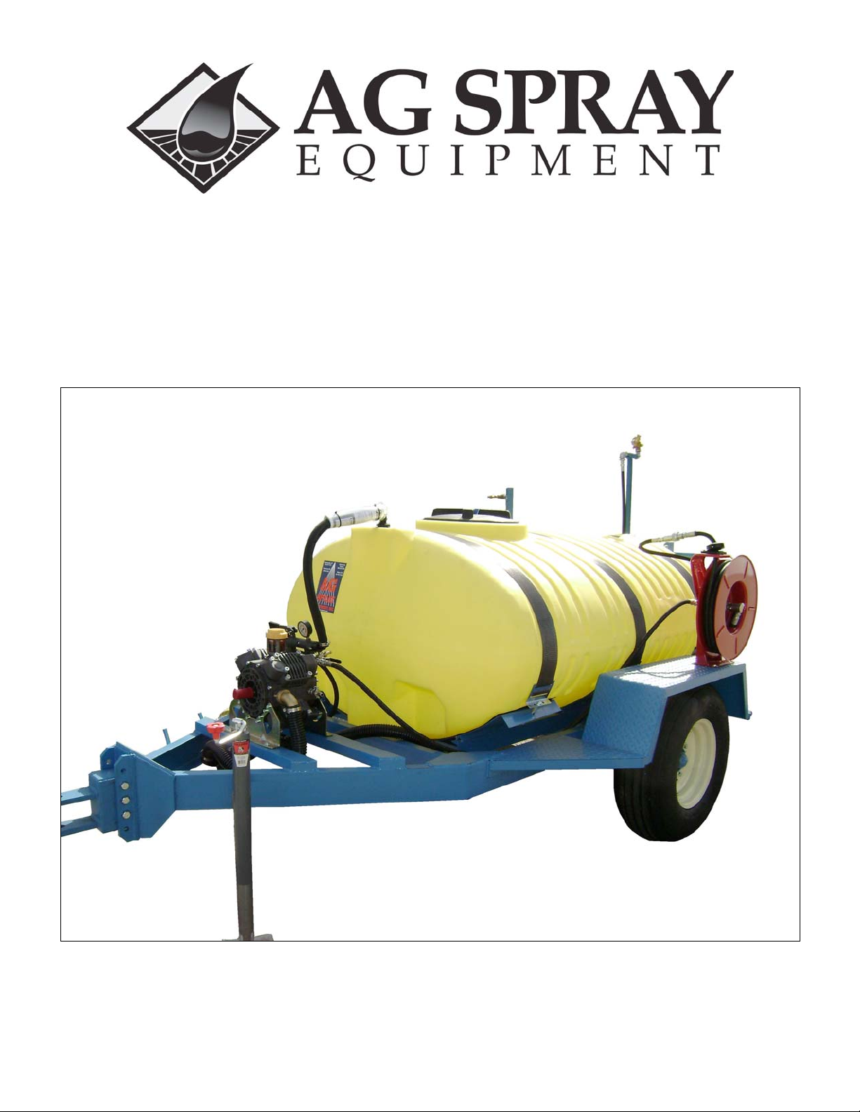
OWNER’S MANUAL
TR500PHS
500 Gallon Poultry House Cleaner
1

AG SPRAY EQUIPMENT OWNER’S MANUAL
Welcome to Ag Spray’s line of sprayers and a special thanks for buying the TR500PHS. The TR500PHS stands for Poultry
House Sprayer with a 500-gallon tank. The sprayer is built with quality, dependability, and service after the sale.
This sprayer is designed to clean and disinfect even the dirtiest of poultry houses. The TR500PHS is built with a boom in a
vertical position on the right hand side, direction of travel, so that it will spray the walls from the floor to the ceiling, and it has an
easy to move boom pipe so you can spray the floor as well. Also, the TR500PHS is built with a boom jet nozzle that will clean
the ceiling and is located on the very back and in the center of the sprayer so that it is easy to change the direction of the spray.
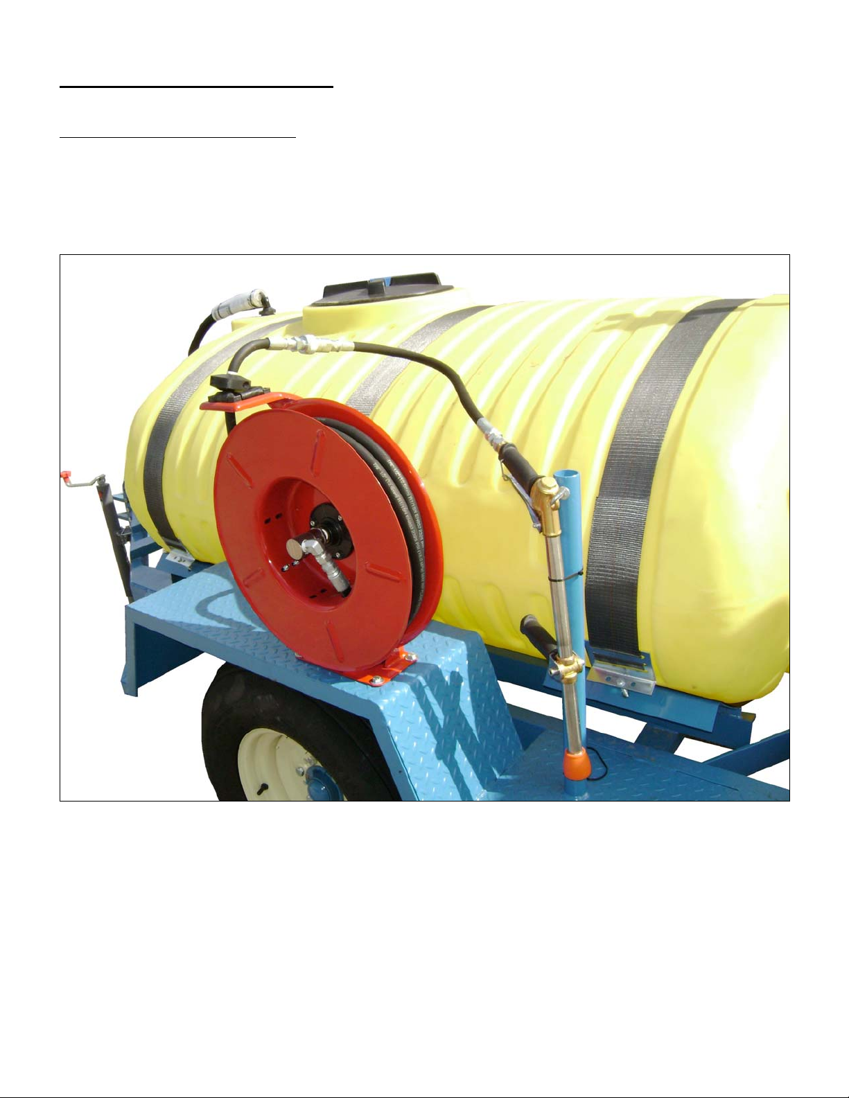
Another great feature of the TR500PHS is the 800 psi handgun with a hose reel to clean and disinfect those hard to reach places
where the booms may not be able to reach very well. Further more, this sprayer is designed to do all this and maneuver in the
poultry house with the greatest of ease.
This booklet is made to inform you of the maintenance and operation needed to use this sprayer. This booklet’s intention is to
familiarize the owner with the machine before operation. So, please, take time to read over this booklet and take the proper
precautions before using the TR500PHS.
Ag Spray Equipment would like to thank you again for choosing this product and if you have any questions feel free to give us a
call at 1-800-637-7172. Make your poultry house a clean one.
WARRANTY
All Field Sprayers are under warranty by Ag Spray Equipment for a one year period from the date of purchase. This warranty
only applies to defects in workmanship or manufactures defects in their components. This warranty does not cover any misuse,
abuse, or parts that may freeze & break. Owners are responsible for these issues. Parts proven defective within the one-year
period will be replaced at no charge.
Ag Spray Equipment must be notified immediately of any defects or parts broken due to shipping on the sprayer. After the oneyear period all warranty is void. No product will be accepted for return without authorization. All returned goods must be
packaged securely and shipped with transportation charges prepaid.
For further information regarding parts or warranty, contact:
Ag Spray Equipment
1100 New Industry Lane
Hopkinsville, KY 42240
Phone: 1-800-637-7172
2

Operation & Instructions of New Sprayer
Check for OVERHEAD clearance – pay special attention if the center boom is up.
Before starting work, analyze the area to determine the best – and safest – operating procedure. Plan your
travel straight forward, whenever possible. Avoid sharp turns at high speeds.
TR500PHS comes equipped with slip resistant steps for use when loading water or chemicals. Always use
them when mounting or dismounting.
WARNING! Never stand or allow anyone else to stand between the tractor and the sprayer
unless the engine is turned off and parking brake is engaged and the transmission is in park (or
neutral). For stationary PTO operation such as setting the pressure regulator, always place
transmission in park (neutral), engage parking brake and block both tractor and the sprayer tires.
Hitching and Unhitching
All towed loads including the TR500PHS must be hitched to the drawbar.
WARNING! Never allow anyone to stand between the tractor and the TR500PHS while the
tractor is backing up.
To unhitch, move to level ground, block the tires and set the jack before unhitching. Be sure to unlatch and
disengage PTO to complete unhitching. Make sure you use a proper safety hitch pin with safety clip
retainer.
Chemical Operations
Always wear the proper clothing and equipment when handling chemicals. The chemical package should
tell you what is needed.
When dry chemicals are to be used, they should be added when the tank is partially filled and the bypass
agitation valve will start mixing. By the time the tank is filled, the chemicals should be thoroughly mixed.
(The return flow from the pressure regulating valve, while the pump is running, is enough to keep chemicals
mixed during operation.)
It is important to keep dry chemicals mixed because when you do not, they settle out forming a hard, crusty
sediment in:
-The diaphragm pump - if this happens the pump may lock up the next time you try to spray possibly
causing pump damage, PTO shaft damage and grave personal injury.
-The tank – always thoroughly flush the system after chemical operations.
NOTE: Do not use chlorine or Chlorinated liquids or products (like Clorox) to flush the pumps or circuits.
3

Operating Procedures
Tractor Selection
Power
The Diaphragm Pump requires 20 h.p. min. Your tractor should have 25-30 horsepower available on the
PTO shaft. It also needs to have the ability to stop the TR500PHS when full of water. A small tractor is
more maneuverable in a poultry house. We recommend using a tractor with a 45 to 60 HP available on the
PTO.
PTO
Our PHS500 comes equipped with a constant velocity drive shaft. The diaphragm pump is designed to
operate at a 540 rpm speed. Tractors come standard with a maximum PTO Speed of either 540 or 1000 rpm.
The shape of the PTO Shaft usually indicates the PTO Speed.
Small tractors (80 hp or less) generally come standard with 540 rpm PTO (1 3/8” shaft with six splines).
Large tractors (80 hp or more) generally come stock with 1000 rpm PTO (1 3/8” or 1 _” shaft with 21
splines).
WARNING! Do not try to operate your TR500PHS with a 1000 RPM PTO!
4
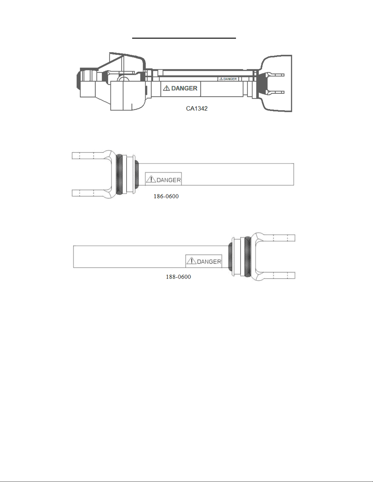
PTO COMPONENTS
COMPLETE PTO SHAFT ASSEMBLY
Part # DS13854037
YOKE AND TUBE ASSEMBLY - FEMALE
YOKE AND BAR ASSEMBLY - MALE
5

Pre-Start Conditions
A. Check that the tank is full if using water only, half full if you are to add chemicals.
B. Check that the PTO shaft and attached pump shaft turns freely by hand (DO NOT
attach PTO shaft or operate the pump if the pump does not turn freely by hand
because it may be locked up and may cause serious injury).
C. Attach PTO shaft and lock it.
D. Check that all shields are in place.
E. Check that there is oil showing in the sight glass of the pump. If low, add
SAE30HD.
F. Clean and inspect strainer screen.
G. Check all hoses and fittings for tightness, wear and leakage.
H. Set the following valve lineup:
1) Pump suction valve OPEN
2) Pressure control valve – pressure adjusting handle in the UP position
3) Hose reel ball valve CLOSED
4) Rear boom ball valve OPEN
5) All individual nozzle isolation valves set to achieve desired pattern
I. Check the oil, water and fuel on the tractor.
J. Check lug nuts and check tire pressure (40 psi cold inflation)
6
TR500PHS Specifications
500 Gallon Polyethylene Tank
It comes with:
A. Large fill cap for easy fill and chemical mixing
B. Rectangular sump with the tank drained through the strainer drain
7

Spray Booms
All nozzles have individual valve cutoffs for differing spray patterns.
Center vertical boom – cluster nozzle (20 GPM with a 20 ft. radius range) creates a circular
spray pattern generally used to clean the rafters, but in the inverted position and at reduced pressure
(100 psi) can be used to disinfect the floor.
Lateral spray boom – has spring loaded and self-centering breakaway feature. Five individual
50-20 spray nozzles (50 degree spray angle and a 2 GPM spray rate each) for a possible 10 GPM.
This boom can also be rotated down to the horizontal position for disinfecting the floor at reduced
pressure (100 psi). All side boom nozzles can be adjusted vertically and the valve bodies can rotate
270 degrees for varied spray patterns.
On ball valves, handle position indicates whether the valve is open or closed (handle parallel with
valve body, valve is open – handle across valve body, valve is closed.)
1. Disconnect the quick coupled hi pressure hose feeding boom.
2. Loosen the 4 T bolts on the two horizontal pipes and slide boom out.
3. Loosen inside T bolts on vertical pipes to remove the two short vertical pipes.
4. Place the two short vertical pipes on the boom horizontally and hand tighten T bolts.
5. Insert the boom into the short horizontal pipes with nozzles facing down.
6. Adjust the nozzles to the desired height and retighten all T bolts.
7. Reconnect hi pressure hose feeding boom.
8
9101112131415161718192021
 Loading...