

Page 1
CONTINUING TO
MANUFACTURE AND SELL
QUALITY SCHABEN PRODUCTS.
operation & maintenance manual
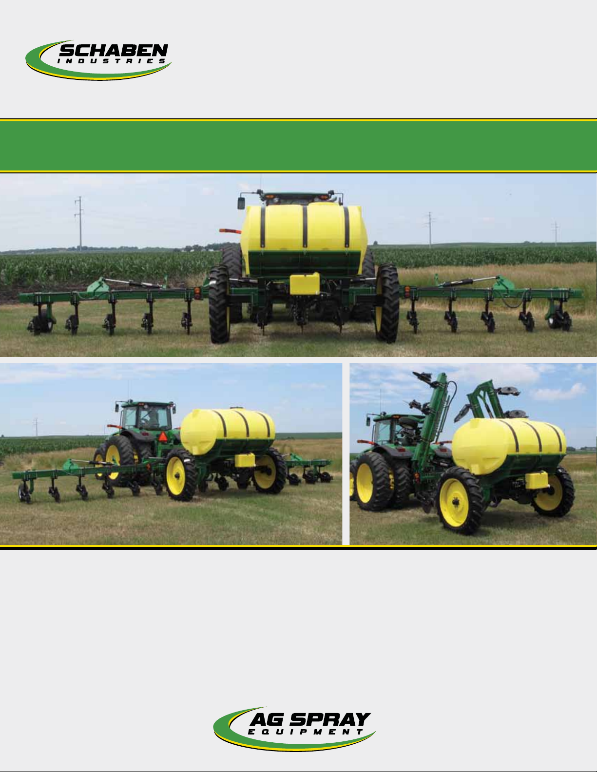
LA5000
BAKERSFIELD, CA
4450 STATE RD, 93308
877.724.2236
COLUMBUS, NE
5834 E 23RD ST, 68601
800.274.1025
VISIT US ONLINE @ WWW.AGSPRAY.COM
DOTHAN, AL
1563 S OATES ST, 36301
800.227.4098
GREENWOOD, MS
104 EASTMAN ST, 38930
800.844.4524
HOPKINSVILLE, KY
1100 NEW INDUSTRY LN, 42240
LIQUID
APPLICATOR
800.637.7172
NEWTON, KS
7000 SCHABEN CT, 67114
800.394.7662
OTHELLO, WA
81 E PINE ST, 99344
800.634.2026
TEMPE, AZ
8464 S KYRENE RD, 85284
877.974.7166
Page 2

INTRODUCTION
1. Read and understand the Operators Manual and all
safety signs before using.
2. Place all controls in neutral, stop tractor engine, turn
monitor off, set park brake, remove ignition key, wait
for nozzles to stop spraying before servicing,
adjusting, or repairing.
3. Before using it in a field, be familiar with all potential
hazards: trees, rocks, ditches, gullies, etc. Plan the
spraying route to avoid hazards. Remember you are
driving a wide machine. USE CAUTION WHEN
CORNERING.
4. Keep hands, feet, hair and clothing away from all
moving and/or rotating parts.
5. Do not allow riders on the applicator or tractor during
operation or transporting.
6. Clear the area of all bystanders, especially children,
before starting or filling with water or chemical.
7. Stay away from wing pinch points when folding or
extending wings. Keep others away.
8. Stay away from power lines when extending or
folding wings. Electrocution can occur without
direct contact.
13. In case of poisoning, get immediate medical attention.
15. Do not eat in the field when side dressing.
16. Before applying pressure to the hydraulic system,
make sure all components are tight and that steel
lines, hoses and couplings are in good condition.
17. Before applying pressure to fertilizer system make
sure that all connections are tight and that all hoses
and fittings are in good condition.
18. Review safety instructions annually.
PRE-OPERATION CHECKLIST
Before operating the Applicator and each time thereafter,
the following areas should be checked off:
1. Lubricate the machine per the schedule outlined in
the “Maintenance Section”.
2. Use only a tractor of adequate power and weight to
operate the Applicator.
3. Ensure that the machine is properly attached to the
tractor. Be sure that a mechanical retainer is installed
through the drawbar pin and the safety chain is
attached to the drawbar cage. Jack is in full up
position.
4. Check the hydraulic system. Ensure that the
hydraulic reservoir in the tractor is filled to the
required specifications.
5. Inspect all hydraulic lines, hoses, fittings and couplers
for tightness. Use a clean cloth to wipe any
accumulated dirt from the couplers before
connecting to the hydraulic system of the tractor.
7. Calibrate the Applicator if it is the start of the season
or a new chemical is being used. Calibrate as
specified in rate control manual.
8. Check the condition and routing of all chemical hoses
and lines. Replace any that are damaged. Re-route
those that are rubbing pinched or crimped.
9. Check the spray pattern of each nozzle. Remove and
clean or replace any that have an unusual pattern.
10. Remove the steel mesh line filters and wash with
clean water. Reinstall.
11. Check that all connections in the electrical system are
connected and tight.
13. Before unfolding boom remove transport wing lock
pins (Figure 7) and tower cylinder Transport stop
(Figure 6) Reinstall lock pins and tower stop
before parking sprayer.
6. Check the tires and ensure that they are inflated to
the specified pressure.
1 - LA5000 LIQUID APPLICATOR OPERATION & MAINTENANCE MANUAL
Page 3

PLACING IN STORAGE
At the end of the spray season, the machine should be thoroughly inspected and prepared for storage. Repair or replace
any worn or damaged components to prevent any unnecessary
down time at the beginning of the next season. Follow this
procedure:
1. Thoroughly wash the machine using a hose or a
pressure washer to remove all dirt, mud, debris or
residue.
2. Thoroughly wash the inside of the tank.
3. In climates that encounter freezing temperatures
during the storage period, the following
preparation should be done:
a. Add 10 gallons (40 liters) of a potable RV
antifreeze to the tank.
b. Run unit for 5 minutes in the spray cycle to
circulate solution to all parts of the circuit.
c. While circulating the fluid, open and close all the
valves in the system to flush all the water from
the system.
e. Flush the solution out the booms.
f. Open all disconnects and drain hoses, pumps,
filters, solenoids and tanks.
g. Remove nozzles from boom Disassemble and
wash nozzle, Spring, diaphragm and housing.
Store inside.
4. Lubricate all grease points. Make sure all grease
cavities have been filled with grease to remove
any water residue from the washing.
5. Inspect all the hydraulic hoses, couplers and fittings.
Tighten any loose fittings. Replace any hose that
is badly cut, nicked, abraded or is separating from
the crimped end of a fitting.
6. Inspect all the spray hoses and fittings. Tighten any
loose fittings. Replace any hose That is badly
cut, nicked, abraded or is separating from a fitting.
7. Touch up all paint nicks and scratches to prevent
rusting.
**STORAGE SAFETY**
1. Store unit in an area away from human activity.
2. Do not permit children to play on or around the
stored applicator.
3. Unhook and store in the transport configuration.
REMOVING FROM STORAGE
When removing from storage and preparing to use,
follow this procedure.
1. Clear the area of bystanders, especially small
children, and remove foreign objects from the
machine and the working area.
2. Check
a. Tank for cracks
b. Tank hold down hardware
c. All hardware. Tighten as required.
d. Tire pressure.
e. All sprayer and hydraulic lines, fittings and
connections. Tighten as required.
3. Lubricate all grease fittings.
4. Replace any defective parts.
5. Fill the tank with 20 gallons (75 liters) of clean water
and run for 5 minutes. Open and close all valves
several times. Flush water through the booms.
6. Repeat step 5.
7. Calibrate the pump, nozzles and sprayer before using.
8. Go through the pre-operation checklist before using.
AGSPRAY.COM 2
Page 4
LIMITED WARRANTY
Ag Spray Equipment warrants to the buyer that the new machinery is free from defects in material and workmanship.
This warranty is only effective as to any new machinery which
has not been altered, changed, repaired or treated since its
delivery to the buyer, other than by Ag Spray Equipment or its
authorize dealers or employees, and does not apply to accessories, attachments, tools or parts, sold or operated with the
new machinery, if they have not been manufactured by Ag Spray
Equipment.
Ag Spray Equipment shall only be liable for defects in the materials or workmanship attributable to faulty material or bad
workmanship that can be proved by the buyer, and specifically
excludes liability for repairs arising as a result of normal wear
and tear of the new machinery or in any other manner whatsoever, and without limiting the generality of the foregoing,
excludes application or installation of parts not completed in
accordance with Ag Spray Equipment operator’s manual, specifications or printed instructions.
Written notice shall be given by registered mail, to Ag Spray
Equipment within seven (7) days after the defect shall have
become apparent or the repairs shall have become necessary,
addressed as follows: Ag Spray Equipment, 5834 East 23rd
Street, Columbus, NE 68601.
This warranty shall expire 2 years after the date of delivery of
the new machinery.
If these conditions are fulfilled, Ag Spray Equipment shall at
its own cost and at its own option either repair or replace any
defective parts provided that the buyer shall be responsible for
all expenses incurred as a result of repairs, labor, parts, transportation or any other work, unless Ag Spray Equipment has
authorized such expenses in advance.
The warranty shall not extend to any repairs, changes, alterations, or replacements made to the new equipment other than
by Ag Spray Equipment or its authorized dealers or employees.
This warranty extends only to the original owner of the new
equipment.
Rubber parts are not warranted. (including tires, hoses, grommets)
This warranty is limited to the terms stated herein and is in lieu
of any other warranties whether express or implied, and without
limiting the generality of the foregoing, excluded all warranties,
express or implied or conditions whether statutory or otherwise
as to quality and fitness for any purpose of the new equipment.
Ag Spray Equipment disclaims all liability for incidental or consequential damages.
This sprayer is subject to design changes and Ag Spray Equipment
shall not not be required to retro-fit or exchange items on previously sold units except at its own option.
OPERATING INSTRUCTIONS
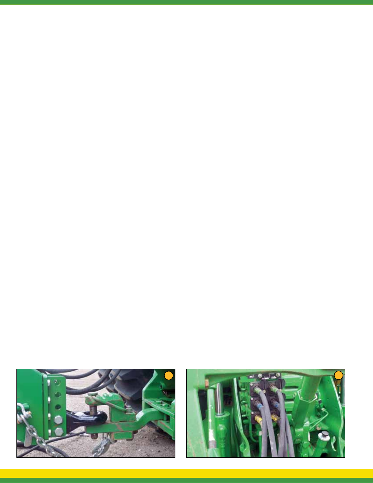
1. Ensure applicator is connected securely to tractor draw bar
with clevis pin and safety chain (Figure 1).
1
3 - LA5000 LIQUID APPLICATOR OPERATION & MAINTENANCE MANUAL
2. Connect applicator hydraulic hoses to the tractor remote
couplers. The blue hoses are for the main bar height control.
The green hoses are for the main wing fold. The yellow hoses
are for secondary wing fold on 35’ bar (Figure 2).
2
Page 5
3. Connect wiring harness if using hydraulic pump with rate
control.
4. Grease Applicator (Refer to Mainentance).
8. After unfolding main wing, engage hydraulic lever in “constant
pressure.” This is necessary to allow wings to maintain
constant depth and follow uneven terrain, as well as the ability
to “gullwing” (Lift both wings evenly when turning. See #9).
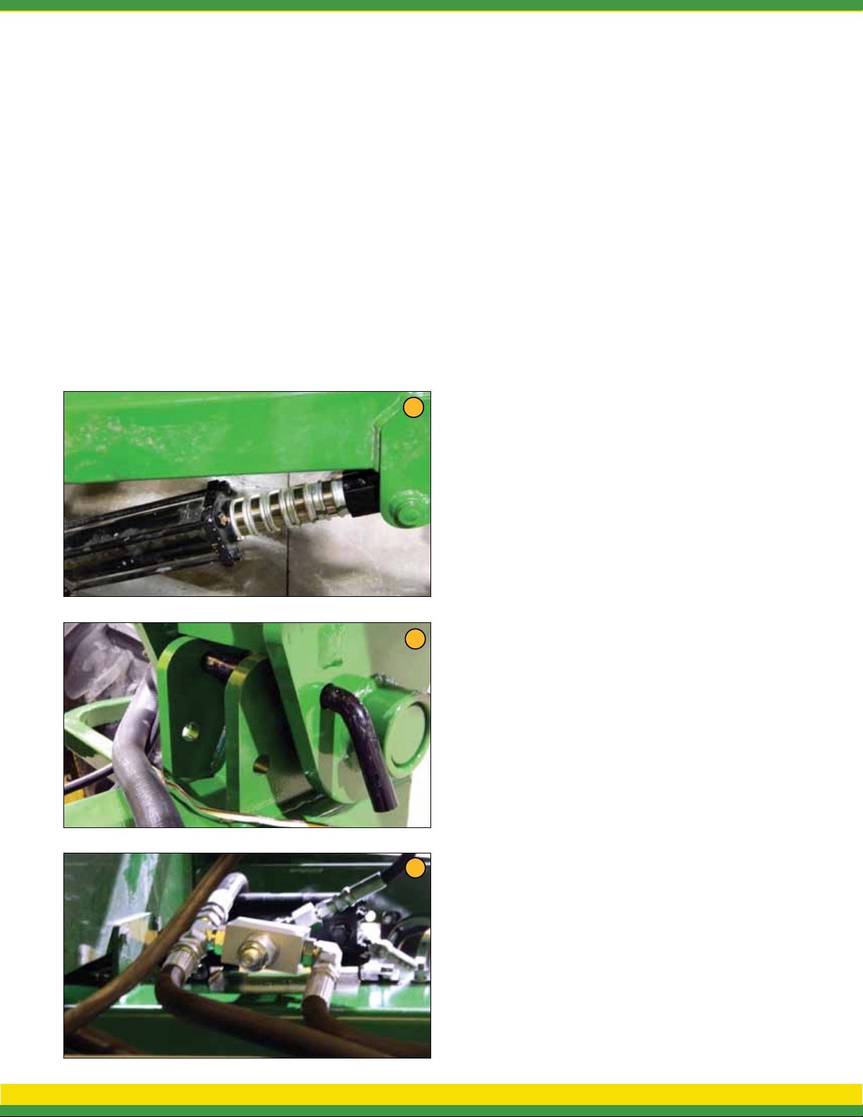
5. Before road travel, install all locking collars on toolbar
cylinders and safety pins on wings.
6. Remove locking collars as needed to maintain a depth of
4 to 5 inches. Constant down pressure on main lift is not
recommended (weight of toolbar will keep unit in the ground).
Leave hydrualic selector in neutral for field operation.
7. Remove safety pins on wing cylinders. Wing cylinders remote
will run in constant while down (Figure 7).
The Applicator is equipped with adjustable down pressure relief
valve on wing cylinders. The valve is preset at 800 PSI. This may
be adjusted as needed. The relief valve is located under tongue,
and requires an allen wrench to adjust (clockwise to increase
pressure and counterclockwise to decrease pressure.) (Figure 8).
6
9. Field Operation: When you come to the end of the field.
1. Lift main section
2. Pull back on main wing lever long enough to lift both
wings slightly (“gullwing”).
3. After turning, lower main section and wing section
and return wing hydraulics to constant pressure.
10. Check and clean screens as needed.
11. Pump Settings
Optional Ground Drive Pump
11a - Remove tranport pin
11b - Use John Blue pump setting slide chart. Loaded radius is
9.75 and sprocket ratio is 32 drive and 18 driven.
11c - Set pump to recommended setting.
Optional Hydraulic Drive Pump
a. Hydraulic pump hoses supplied on the applicator
include (1) 1/2” line and (1) 3/4” line. The 1/2” hose
is the hydraulic supply (in/pressure) and the 3/4”
hose is the return (out/non-pressure).
NOTE: It is recommended for optimal pump performance that
the 3/4” return line connect directly to the tractor hydraulic
reservoir (not tractor SCV port). Doing so eliminates possible
back pressure restriction on the 3/4” return line. Excessive
back pressure restriction can cause hydraulic orbital motor
damage/failure.
b. Proper hydraulic pump disengagement. When shutting off
the pump, move the selector to the FLOAT position to allow
the centrifugal pump to come to a gradual stop. Standard
7
8
spool valves, which are found on all tractor hydraulic systems,
can cause potentially damaging high peak pressures in the
hydraulic system when closed, because of abrupt shutoff of
oil flow in both the supply and return lines.
c. Close and lock down the bypass adjusting screw in the
hydraulic motor (if applicable).
Switch rate controller to manual and press the “+” button on
TeeJet or “Increase” button on Raven, hold for 8 seconds. Then
press the “-” button on TeeJet or “Decrease” button on Raven for
4 seconds.
Set the tractor hydraulic flow control valve for minimum hydraulic
oil flow to the remote outlet (Tortoise position).
Start the tractor and allow the hydraulic oil to circulate for
approximately 10 to 15 minutes or until adequately warmed.
Prime the centrifugal pump with all valves open.
Open the sprayer control regulating valve and the boom shut-off
valves.
Slowly adjust the tractor hydraulic flow control valve until the
desired boom pressure is attained.
NOTE: See manufacture pump operators manual for further
setup and maintenance.
AGSPRAY.COM 4
Page 6

BREAK-IN
Although there are no operational restrictions on the applicator when used for the first time, it is recommended that
the following mechanical items be checked:
A. After operating for 1/2 hour
1. Re-torque all the wheel bolts.
2. Re-torque all other fasteners and hardware.
3. Check that all electrical connections are tight.
4. Check that no fertilizer or hydraulic lines are
being pinched or crimped. Re-align as required.
5. Check that all nozzles are working properly.
Clean or replace as required.
6. Lubricate all grease fittings.
B. After 5 hours and 10 hours of operation
1. Retorque all wheel bolts, fasteners and hardware.
2. Check fertilizer and hydraulic line routing.
3. Check that all nozzles are working properly.
4. Then go to the normal servicing and maintenance
schedule as defined in the Maintenance Section.
5. Lift right hand side of machine and check main
wheel bearing for proper play (slight wobble when pulling
on top of wheel). Repeat for left hand side.
! MAINTENANCE SAFETY !
1 Review the Operator’s Manual and all safety items
before working with, maintaining or operating the
Applicator.
SERVICE AND MAINTENANCE
2. Place all controls in neutral, stop the tractor engine,
turn monitor off, set park brake, remove ignition key,
wait for nozzles to stop spraying before servicing,
adjusting, repairing or unplugging.
3. Follow good shop practices:
- Keep service area clean and dry
- Be sure electrical outlets and tools are properly
grounded
- Use adequate light for the job at hand.
4. Before applying pressure to a hydraulic system, make
sure all components are tight and that steel lines,
hoses and coupling are in good condition.
5. Before applying pressure to fertilized system, make
sure that all connection are tight and that all hoses
and fittings are in good condition.
6. Install wing lock pins and tower stops before relieving
pressure from hydraulic circuit to service Applicator.
9. Place stands or blocks under the frame before
working beneath the machine.
10. Wear safety goggles, neoprene gloves and protective
clothing when working on the Applicator filled with
active chemical.
11. Wash machine to remove all chemical residue before
working on unit. Wear appropriate protective gear at
all times.
12. Protect yourself from chemical contamination.
7. Keep hands, feet, clothing and hair away from all
moving and/or rotating parts.
8. Clear the area of bystanders, especially children,
when carrying out any maintenance and repairs or
making any adjustments or filling.
5 - LA5000 LIQUID APPLICATOR OPERATION & MAINTENANCE MANUAL
Page 7
GREASING
- Wipe grease fitting with a clean cloth before greasing
to prevent injecting dirt and grit into joint.
- Replace and repair broken fittings immediately.
- If a fitting will not take grease, remove and clean
thoroughly. Also clean lubricant passageway.
Replace fitting if necessary.
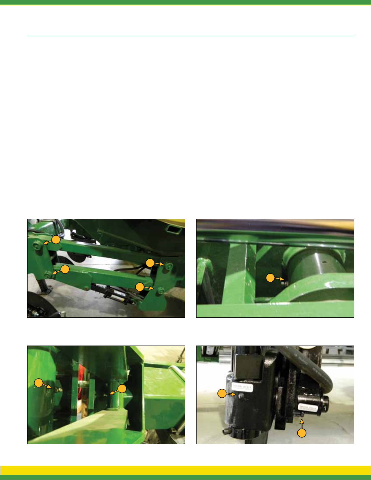
*Note: Grease 20 points 8 hours or daily.
Along with 2 points per coulter. Hubs and
spindles should be greased biannually.
*Note: It is best to grease the machine at
the end of the day to ensure that fertilizer/
chemicals do not have time to start corroding parts.
FIG. 20a
L/R GREASE LOCATIONS
Apply adequate grease to the following:
1. L/R Main Wing Hinge (Fig. 20b)
2. L/R Flip Wing (35’) (Fig. 20c)
3. Coulter Pivots (Fig. 20d)
4. Parallel Hinge Bushings (Fig. 20a)
5. Piston Pump (Refer to pump operators manual)
FIG. 20b
4
4
4
1
4
FIG. 20c
2
2
3
FIG. 20d
3
AGSPRAY.COM 6
Page 8
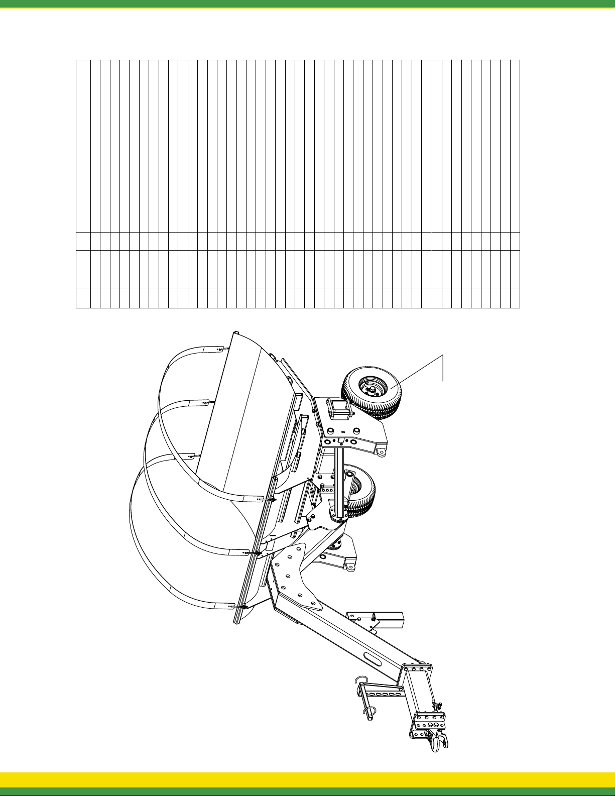
MAIN FRAME PARTS KEY
Description
1/2"-13 Hex Nut
1/2"-13 Hex Locknut
Qty.
Part
Number
2 5006091 34
3 5006092 8
1 50060114
No
Item
3/8"-16 Hex Locknut
5/8"-11 Hex Locknut
3/4"-10 Hex Locknut
3/8"-16 Hex Whiz (Flange) Locknut
3/4"-10 Hex Flange Serrated Locknut
(Plain) Flatwasher, 3/4"
4 5006201 4
5 5006203 21"-8 Hex Locknut
7 5006259 6
8 5006359 32
9 5016183 2
6 5006215 23
3/8" x 6" L-Head Hook Bolt
H.H.C.S. 3/8"-16nc x 1" Long
H.H.C.S. 5/8"-11nc x 4 1/2" Long
H.H.C.S. 3/4"-10nc x 8" Long
H.H.C.S. 3/4"-10nc x 9" Long
10 5034079 8
11 5034147 4
12 5034295 2
13 5034298 6
14 5034470 4
15 5034510 16
Square U-Bolt, 3/4" Dia. x 7 1/8" x 8 1/2"
H.H.C.S. 3/4"-10nc x 2 1/2" Long
H.H.C.S. 1"-8nc x 6 1/2" Long
H.H.C.S., 3/4"-10 x 2" Flange Head (GR8) (ZP)
H.H.C.S. 3/4"-10nc x 7" Long
16 5034547 2
17 5034588 24
18 5034589 4
19 5034590 1
5-Stud Hub Assembly For 1 3/4" Dia Spindle
Gauge Wheel Mount Plate (7" Tube)
S.H.S.S. 1/2-13nc x 1 1/2" Long Cup Pt.
H.H.C.S. 1/2"-13nc x 1 3/4" Long
Machinery Bushing, 3/4" ID x 1-1/4" OD
1/2" Safety Anchor Shackle w/Screw Pin
20 5034591 34
21 5037745 2Axle Brace
22 5041094 2
23 5052019 2
24 5085060 2
25 5095287 4
Cast Hitch
Hitch Pin
1000 Gallon Elliptical TankStrap
26 5101327 1
27 5117104 4
28 5133272 3
29 5274832 1
30 5277451 1LA-5000 Tongue Weldment
31 5277456 1LA-5000 Axle Frame Weldment
Side Brace Weldment
32 5277458 2
Tongue Extension Weldment
Bolt On Hitch Weldment
33 5277462 1
34 5277463 1
LA5000 Jack Swing Tube Weldment
1000 Gallon Elliptical Saddle Weldment
36 5277548 1
35 5277467 1
Hydraulic Pump Mount
37 5277551 1Tank Support Weldment
38 5277568 1
Safety Chain, 3/8" x 37" w/.4375" Clevis Hook
Hose Guide Weldment LA5000
1.750 Spindle Assembly For 545 Hub
39 5277569 2 Gauge Tube Wheel Weldment
40 5277636 1
41 5049042 2
42 5021048 2PROTOUR Wheel
43 5024125 2
GAUGE WHEELS
Wheel Driven Pump Mount Assembly (LA-5000)
44 5277867 1
USED FOR TRANSPORTATION
7 - LA5000 LIQUID APPLICATOR OPERATION & MAINTENANCE MANUAL
Page 9
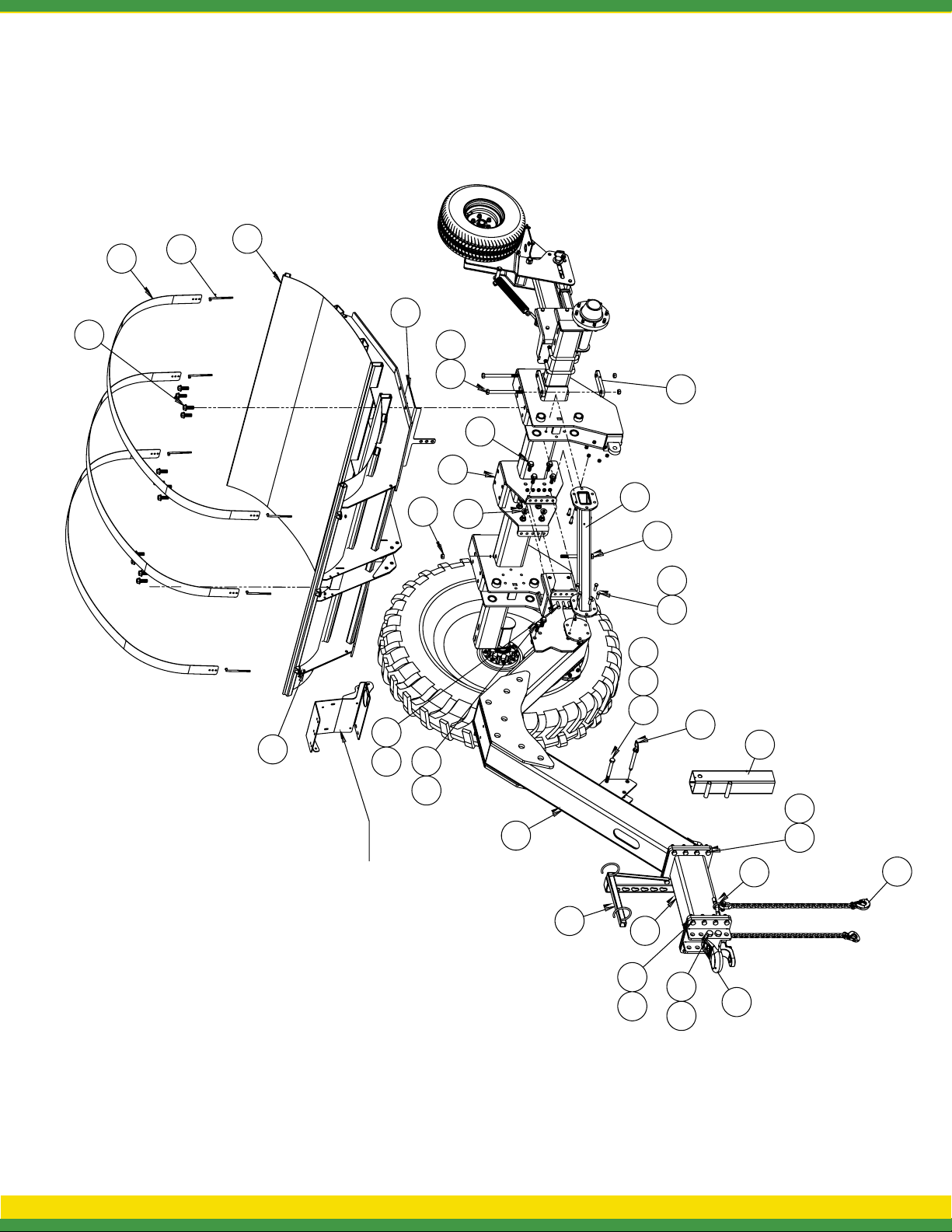
MAIN FRAME FRONT VIEW
17
28
13
36
38
14 6
17
31
6
8
21
32
12
20 2
19 622
7
202
178
SHOWN FOR
VALVE BRACKET
REFERENCE ONLY
30
40
33
156
26
35
15 6
23
165
29
41
AGSPRAY.COM 8
Page 10
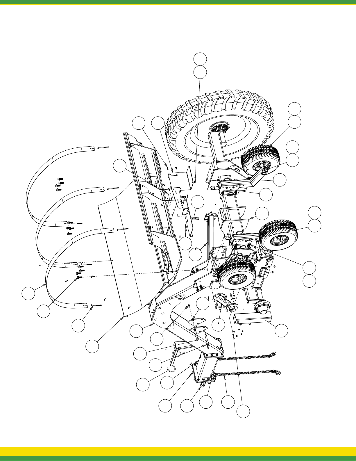
MAIN FRAME REAR VIEW
612
10
3
37
25
38
31
10
32
42 43
27 1
39
11 4
188
28
22
17
23
32
35
41
2
13
36
9 - LA5000 LIQUID APPLICATOR OPERATION & MAINTENANCE MANUAL
30
19
40
6
26
33
34
29
Page 11
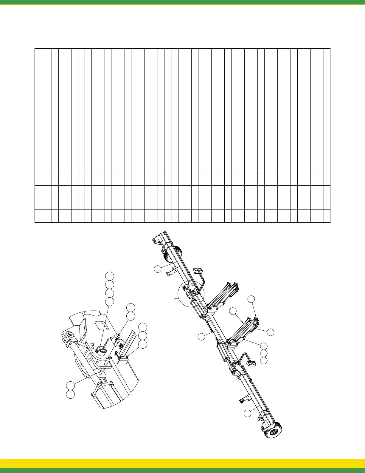
TOOLBAR MOUNT & HINGE ASSEMBLY
Description
3/4"-10 Hex Nut
5/8"-11 Hex Locknut
3/8"-16 Hex Locknut
1/4"-20 Hex Nut
1/2"-13 Hex Nut
1/2"-13 Hex Locknut
4
4
16416
Qty.
3/4"-10 Hex Flange Locknut
3/4"-10 Hex Jam Nut
4
4
Spring Lockwasher 1/4"
Grease Zerk, 1/4"-28 Thread
PROTOUR Wheel
10
15
2
8
H.H.C.S., 5/8"-11 x 4 1/2"
H.H.C.S. 3/8"-16nc x 1" Long
1.750 Spindle Assembly For 545 Hub
4
2
8
Square U-Bolt, 3/4" Dia. x 7 1/8" x 8 1/2"
Square U-Bolt, 1/4" x 1 9/16" x 2 1/8"
H.H.C.S. 3/8"-16nc x 2 3/4" Long
8
8
H.H.C.S 3/4” - 10nc x 3.5” Long (Full Thread)
H.H.C.S. 1/2"-13nc x 3 3/4" Long
Machinery Bushing, 1 1/2" O.D. x 1" I.D. x 10 Ga.
444
2504111320
5-Stud Hub Assembly For 1 3/4" Dia Spindle
Gauge Wheel Mount Plate (7" Tube)
Nozzle Tube (96")
Hyd. Cyl. - 5" x 20" x 2" Rod
Hyd. Cyl., 3" x 8", 1.25" Rod
2
2
Nozzle Tube (59 3/4")
Hair-Pin Cotter (0.120" Dia.)
4
2
2
2
2
Cotter Pin, 3/16" x 2"
Lift Arm Pivot Pin
2
8
S.H.S.S. 1/2-13nc x 1 1/2" Long Cup Pt.
Bent Pin 3/4 Dia. x 9 1/4 Usable Length
Inner Wing Pivot Pin
4
2
2
Short Hose Guide Weldment (R.H.)
Lift Arm Cylinder Pin Weldment
Hose Deflector Strap (Long)
2
8
1
Short Hose Guide Weldment (L.H.)
Center Toolbar Weldment (LA 5000)
Light Mount Weldment
Lower 4-Bar Weldment
Middle Toolbar Weldment R.H. (LA 5000)
2
2
137 5277382
1
1
Middle Toolbar Weldment L.H. (LA 5000)
Upper 4-Bar Weldment (LA-5000)
212
Gauge Tube Wheel Weldment
Part
Number
No
Item
5006041
5006011
2
1
5006093
5006092
5006091
4
5
3
50062016
5006260
7
5016035
5012015
5006359
8
9
101312
3017 3
35
5034079
5024125
5021048
11
7
19
5034473
5034288
5034147
14
16
15
39
4
13
5034589
5034594
5034569
18
19
17
38
5061037
21
A
5095287
5085060
5061046
24
23
22
37
5101065
5100706
5100705
27
26
25
5101315
5101273
5101230
29
28
30
41
5117104
5101322
5133256
33
32
31
40
34
2028
5275425
5275469
5275468
343635
21
5277388
5277391
5277394
384039
5277395
5277437
5277569
414243
3127
DETAIL A
42
AGSPRAY.COM 10
Page 12
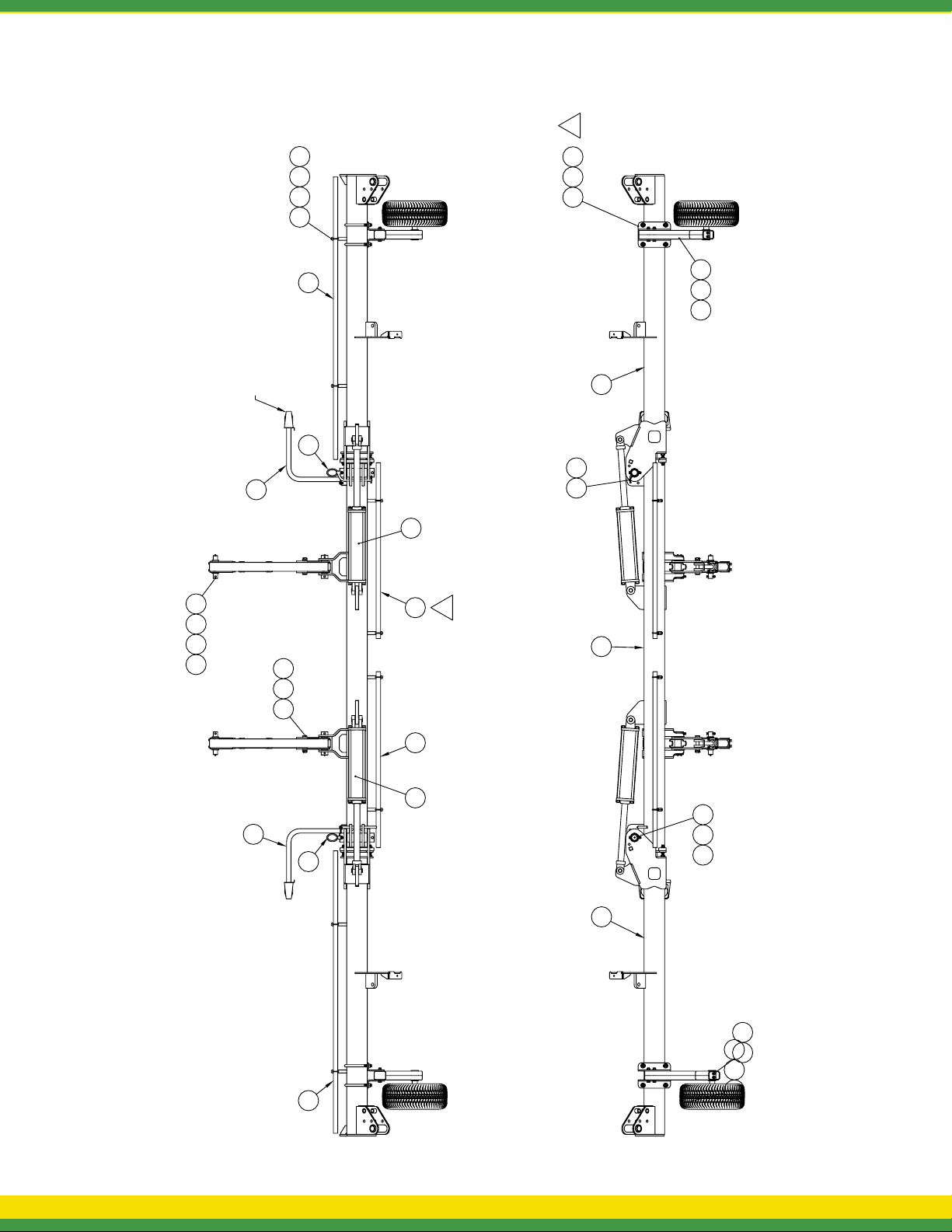
TOOLBAR PARTS KEY - 8 & 12 ROW NARROW SPACING
16
33 10 2
26
SHOWN FOR REF.
36
39
22
2915 9
4
25
1
2418 8 2
14 643
42
3127
37
39
34 20 28
35
26
22 25
38
303
17
23
1211
32 1
11 - LA5000 LIQUID APPLICATOR OPERATION & MAINTENANCE MANUAL
Page 13
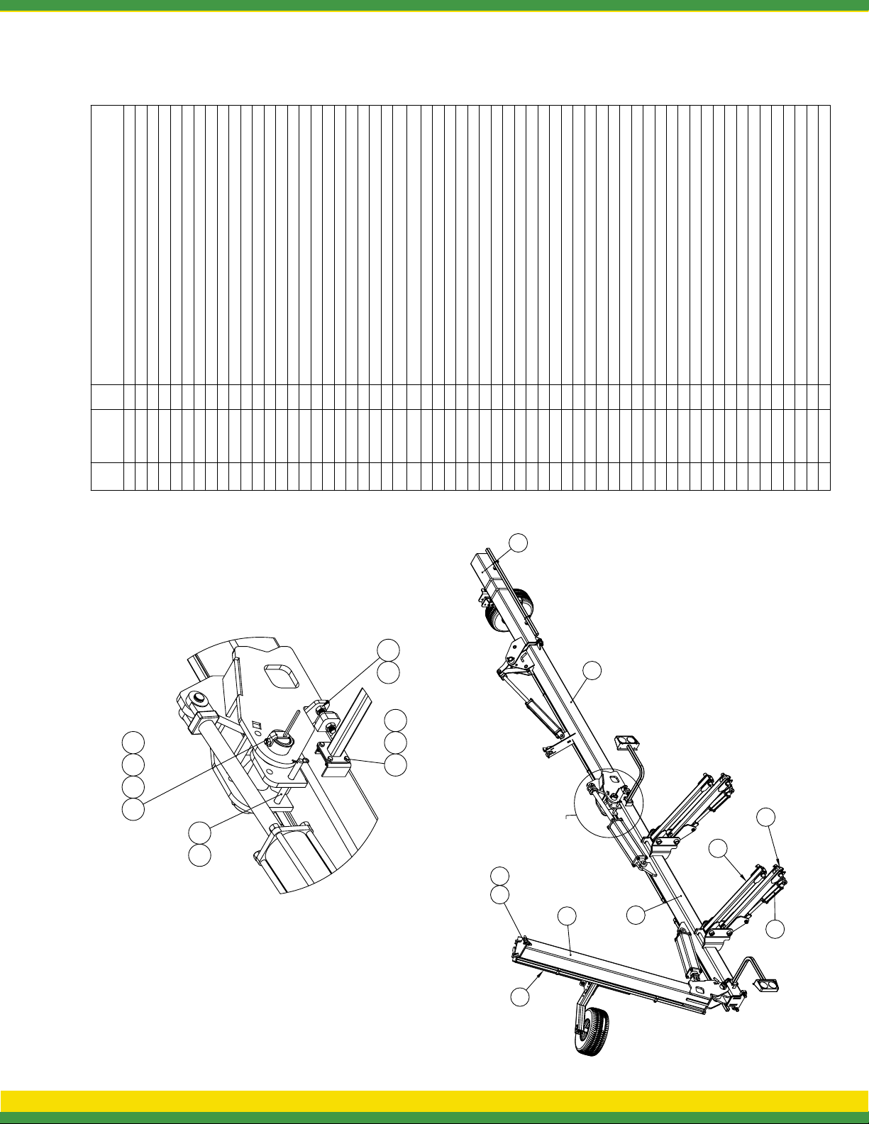
TOOLBAR PARTS LIST
Description
5/16"-18 Hex Locknut
1/2"-13 Hex Locknut
1/4"-20 Hex Nut
1/2"-13 Hex Nut
4
4
8
Number
5006035
5006011
2
1
No
24
5006091
5006041
4
3
Qty.
Part
Item
4
5/8"-11 Hex Locknut
3/4"-10 Hex Jam Nut
3/8"-16 Hex Locknut
3/4"-10 Hex Nut
4
4
6
18
5006260
5006201
5006093
5006092
6
8
5
7
3/4"-10 Hex Flange Locknut
Spring Lockwasher 1/4"
Grease Zerk, 1/4"-28 Thread
850063599
23
14
5016035
5012015
11
10
PROTOUR Wheel
2
5021048
12
H.H.C.S. 3/8"-16nc x 1" Long
H.H.C.S. 3/8"-16nc x 3" Long
H.H.C.S. 5/16"-18nc x 1" Long
1.750 Spindle Assembly For 545 Hub
4
2
2
8
5034079
5034078
5034042
5024125
15
16
14
13
Square U-Bolt, 1/4" x 1 9/16" x 2 1/8"
H.H.C.S., 3/4"-10 x 2 1/2"
H.H.C.S. 3/8"-16nc x 2 3/4" Long
H.H.C.S., 5/8"-11 x 4 1/2"
H.H.C.S. 5/16"-18nc x 2" Long (Full Thread)
4
4
5034082
17
2
8
12
5034510
5034473
5034288
5034147
21
20
19
18
Square U-Bolt, 3/4" Dia. x 7 1/8" x 8 1/2"
H.H.C.S 3/4” - 10nc x 3.5” Long (Full Thread)5034594
Bumper4
4
4
5040015
5034589
25
24
23
Machinery Bushing, 1 1/2" O.D. x 1" I.D. x 10 Ga.
6
5041113
26
H.H.C.S. 1/2"-13nc x 3 3/4" Long
4
5034569
22
5-Stud Hub Assembly For 1 3/4" Dia Spindle
Gauge Wheel Mount Plate (7" Tube)
Nozzle Tube (59 3/4")
Hyd. Cyl. - 3" x 20" x 1.5" Rod
Hyd. Cyl. - 5" x 20" x 2" Rod
Hyd. Cyl., 3" x 8", 1.25" Rod
4
2
2
2
2
2
5085060
5061048
5061046
5061037
28
27
29
30
5100705
509528731
32
Cotter Pin, 3/16" x 2"
Nozzle Tube (56")
Nozzle Tube (96")
2
2
5100707
5100706
34
33
Lift Arm Pivot Pin
Hair-Pin Cotter (0.120" Dia.)
Front Cylinder Pin
4
2
2
8
5101273
5101256
5101230
5101065
37
38
36
35
52
824
5
16 53
Outer Wing Pivot Pin
Linkage Pivot Pin
Inner Wing Pivot Pin
222
2
5101315
5101316
5101317
41
40
39
S.H.S.S. 1/2-13nc x 1 1/2" Long Cup Pt.
Linkage Pivot Pin
Bent Pin 3/4 Dia. x 9 1/4 Usable Length
4
5101318
5101322
43
42
Lift Arm Cylinder Pin Weldment
External Snap Ring 1"
Hose Deflector Strap (Long)
4
4
2
12
5110316
5117104
5275425
5133256
454448
47
46
51
Short Hose Guide Weldment (R.H.)
Short Hose Guide Weldment (L.H.)
Outer Toolbar Weldment R.H. (LA 5000)
Center Toolbar Weldment (LA 5000)
Light Mount Weldment
Middle Toolbar Weldment R.H. (LA 5000)
111
1
5275468
5275469
49
2
1
5277382
5277388
5277389
5277391
515054
53
52
Link Arm Double Weldment
2
5277392
Middle Toolbar Weldment L.H. (LA 5000)
Link Arm Weldment
Lower 4-Bar Weldment
Upper 4-Bar Weldment (LA-5000)
2
2
212
1
5277393
5277394
5277395
5277437
55
5657596058
Outer Toolbar Weldment L.H. (LA 5000)
Gauge Tube Wheel Weldment
5277438
5277569
48 39 22
35 43
A
56
57
821
58
50
27
DETAIL A
59
AGSPRAY.COM 12
Page 14
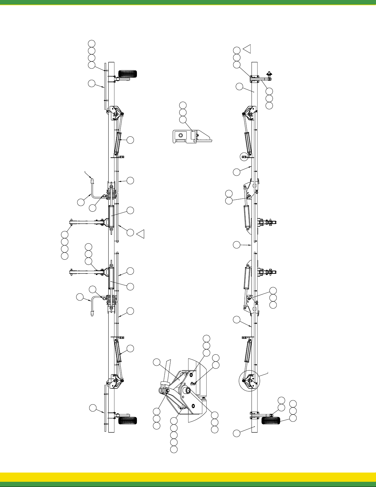
TOOLBAR PARTS KEY - 12 & 16 ROW WIDE SPACING
2
92331
3810
19
5
53
34 46 20 311
2
1425
29
DETAIL B
SHOWN FOR REF.
3332
49
36
26
47
28
1
3543
B
58
50
59
60
7
18
53
48
34
2833 32
29
55
37
44
26
54
4110 17 2
21742
3543
DETAIL C
15 40
5
51
52
C
39
4
22
1
45
301312
13 - LA5000 LIQUID APPLICATOR OPERATION & MAINTENANCE MANUAL
Page 15
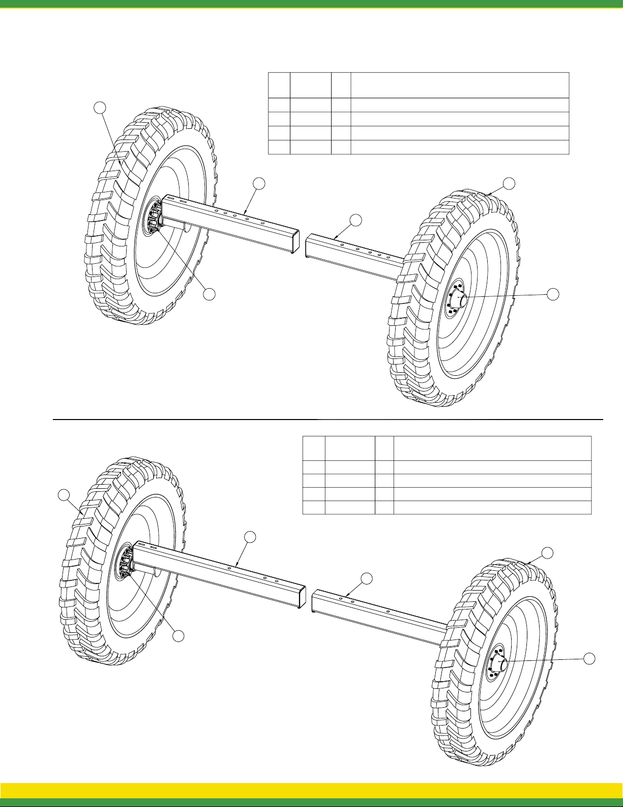
AXLE & TIRE ASSEMBLY
Item Part
Number
No
5277397
4
2
1
5085016
2
5275413
3
4
1
Description
Qty.
2
Axle Weldment 3" Spindle - 96", 102",110" & 120"
2
Hub Assembly (758) (8-Bolt)
1
Wheel/Tire Assembly (LH)
15275414
Wheel/Tire Assembly (RH)
3
1
2
Item
1
2
3
4
1
3
4
Part
NumberNo
5085016
5275413
5275414
Description
Qty.
2
Hub Assembly (758) (8-Bolt)
1
Wheel/Tire Assembly (LH)
1
Wheel/Tire Assembly (RH)
25277662
Axle Weldment 3" Spindle - 120", 144" & 152"
2
4
1
AGSPRAY.COM 14
Page 16
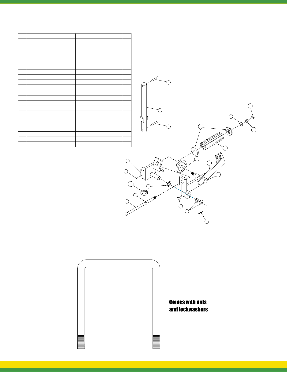
8
COULTER ASSEMBLY
Item
Part #
KSC-466360-RP7161
2
KSC-466315 (20" & 24")
3
KSC-466320
4
KSC-466360-MB10
5
MF6H
6
106-N1
7
KSC-466360-MB14
8
KSC-466360-CP
9
KSC-466360-GF
10
KSC-466300-HUB
11
KSC-531020
12
SPR-1 (20"&24")
13
S1244SL-SPC
14
N6
15
N6J
16
KSC-466300-SPL
17
KSC-466315-C
20 PL COMBO (NOT SHOWN)
20 FL COMBO (NOT SHOWN)
20 FLC COMBO (NOT SHOWN)
20 NO COMBO (NOT SHOWN)
Spring Pin, 7/16 X 3
COULTER SHAFT
COULTER PIVOT ASSEMBLY
Machine Bushing 10 ga
Washer, Flat, 3/4" High Strength
HHCS,3/4" X 14" BOLT GR.5
Machine Bushing, 14 ga
Cotter Pin, 1/4 X 2
Drive Zerk
N633 Hub Assembly With Bearings
COLTER ARM ASSEMBLY
MAIN SPRING
SPRING CAP WELDMENT
NUT, HEX, 3/4" High Strength
NUT, HEX, JAM, 3/4" PLAT ED
N633 Spindle W/ Hardware
COLLAR
20" SMOOTH BLADE
20" FLUTED BLADE
20" CRUCIBLE BLADE
20" NOTCHED BLADE
QTYDESCRIPTION
2
1
1
1
2
1
2
1
2
1
1
1
2
1
1
1
1
1
15
2
5
1
13
14
12
3
9
10
11
16
17
4
5
6
9
7
3/4” U-BOLT FOR 7 X 7 TOOLBAR
15 - LA5000 LIQUID APPLICATOR OPERATION & MAINTENANCE MANUAL
Page 17
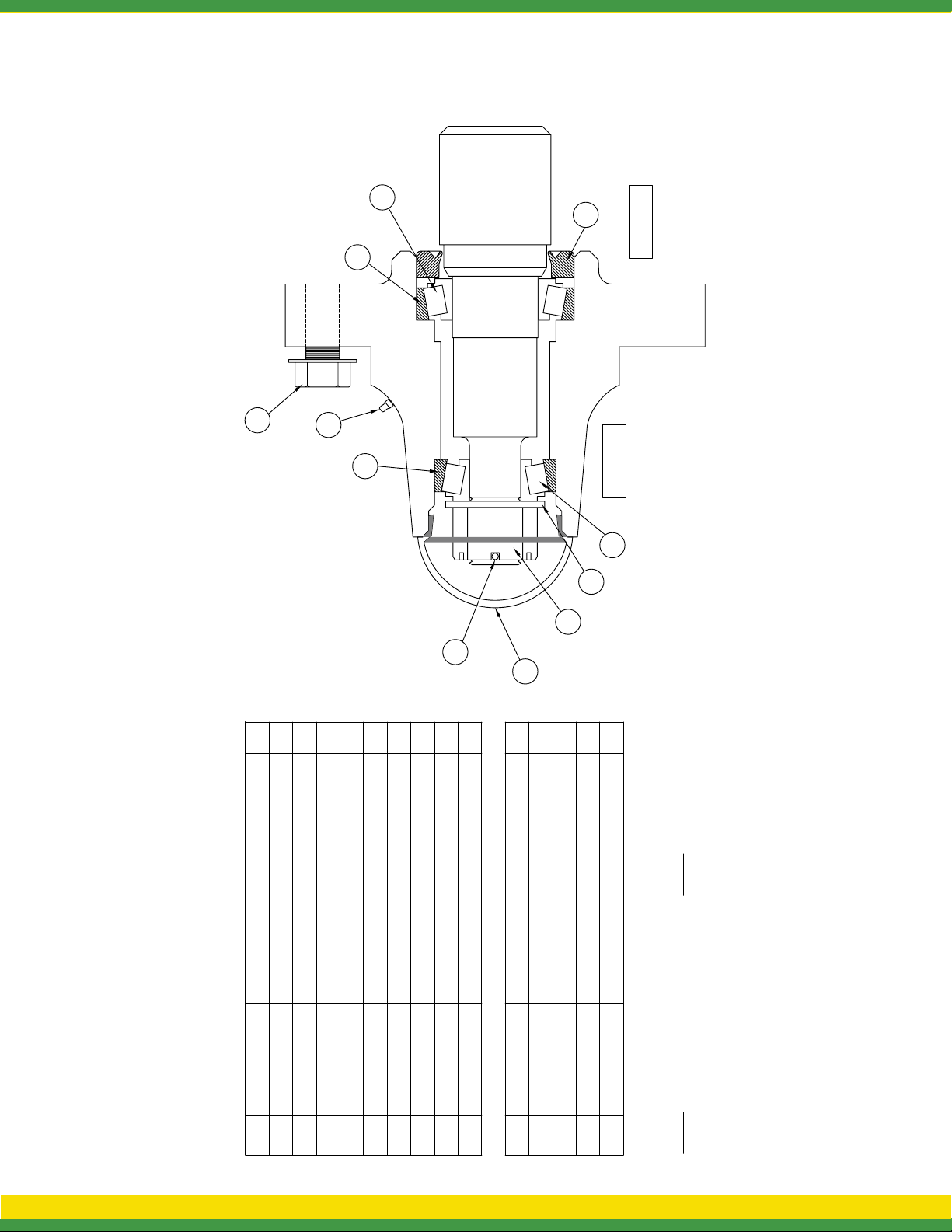
COULTER HUB
3
6
1
7
8
INNER
2
OUTER
4
9
10
11
5
QTY
Description
Part #
Item
1
Inner Bearing Cup(large race)
Comes Complete With Items 1-8
KSC-466300-HUB
1 KSC-LM67010
1
1
1
1
Outer Bearing Cup(small race)
Inner Bearing Cone (large rollers/cage)
2 KSC-LM11910
3 KSC-LM67048
4 KSC-LM11949
1
4
Outer Bearing Cone (small rollers/cage)
Hub Cap
Seal
Flange Head Bolts (each)
KSC-909911
KSC-906296
KSC-913572
5
7
6
1
KSC-G1641-B
8
QTY
Description
1/4-28 X 35/64 Grease Zerk
Part #
Item
1
Spindle Washer
Comes Complete With Items 9-11
KSC-913608
KSC-466300-SPL
9
1
1
Spindle Castle Nut
Spindle Cotter Pin
KSC-912953
KSC-905936
10
11
Spindle P/N KSC-466300-SPL
Comes Complete With Items 9-11
Note:
Comes Complete With Items 1-8
Note: HUB P/N KSC-466300-HUB
AGSPRAY.COM 16
Page 18
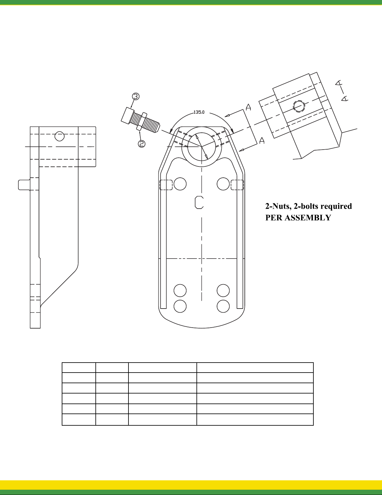
7 X 7 STANDARD COULTER MOUNT
ITEM# QTY. PART# DESCRIPTION
1 1 KSC-466670C Casting
2 2 N6J 3/4 - 10 Jam Nut
3 2 106-B1 3/4 - 10 x 2 Square Head Set Screw
1 1 KSC-466571-4R 4” Right Hand Off-set Mount
1 1 KSC-466571-4L 4” Left Hand Off-set Mount
17 - LA5000 LIQUID APPLICATOR OPERATION & MAINTENANCE MANUAL
Page 19
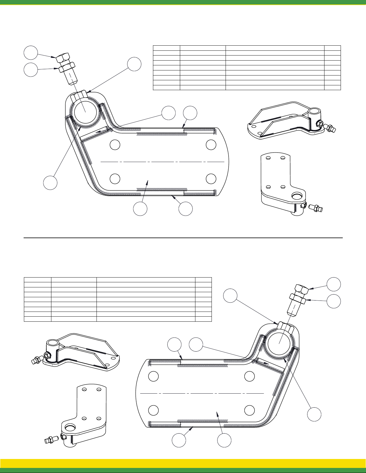
7 X 7 OFFSET COULTER MOUNT
8
ITEM NO.
6
7
PART NUMBER
1
KSC-466571-4MP
KSC-466340-BMT
2
KSC-466571-4GL
3
4
KSC-466571-4G1L
5
KSC-466340-4G2
6
N6H
7
N6J
8106-B1
5
4
DESCRIPTION
COULTER MOUNT PLATE, 7", 4" OFFSET
BAR MTG TUBE
KSC-466571-4G FORMED OFFSET GUSSET
KSC-466571-4G1 FORMED OFFSET GUSSET
OFFSET COULTER MOUNT GUSSET
NUT, HEX 3/4-10 GR 2
NUT, HEX JAM
SET SCREW 3/4-10 X 2 SQ HEAD CUP PT
QTY.
1
1
1
1
1
1
1
1
2
31
ITEM NO.
PART NUMBER
KSC-466571-4MP
1
KSC-466340-BMT
2
3 KSC-466571-4GR
4 KSC-466571-4G1R
KSC-466340-4G2
5
6
N6H
N6J
7
8 106-B1
DESCRIPTION
COULTER MOUNT PLATE, 7", 4" OFFSET
BAR MTG TUBE
KSC-466571-4G FORMED OFFSET GUSSET
KSC-466571-4G1 FORMED OFFSET GUSSET
OFFSET COULTER MOUNT GUSSET
NUT, HEX 3/4-10 GR 2
NUT, HEX JAM
SET SCREW 3/4-10 X 2 SQ HEAD CUP PT
4
31
5
QTY.
1
1
1
1
1
1
1
1
8
6
7
2
AGSPRAY.COM 18
Page 20
LIQUID
LA5000
APPLICATOR
operation & maintenance manual
BAKERSFIELD, CA
4450 STATE RD, 93308
877.724.2236
P: 661.391.9081 • F: 661.391.9085
HOPKINSVILLE, KY
1100 NEW INDUSTRY LN, 42240
800.637.7172
P: 270.885.0296 • F: 270.885.7392
COLUMBUS, NE
5834 E 23RD ST, 68601
800.274.1025
P: 402.564.4544 • F: 402.564.0549
NEWTON, KS
7000 SCHABEN CT, 67114
800.394.7662
P: 316.283.4444 • F: 316.283.4646
DOTHAN, AL
1563 S OATES ST, 36301
800.227.4098
P: 334.673.0580 • F: 334.673.1974
OTHELLO, WA
81 E PINE ST, 99344
800.634.2026
P: 509.488.6631 • F: 509.488.2927
GREENWOOD, MS
104 EASTMAN ST, 38930
800.844.4524
P: 662.453.4524 • F: 662.455.4442
TEMPE, AZ
8464 S KYRENE RD, 85284
877.974.7166
P: 480-705-8047 • F: 480-705-8048
FM 3024
 Loading...