

Ag Spray BA7SQK User Manual
Owner's Manual
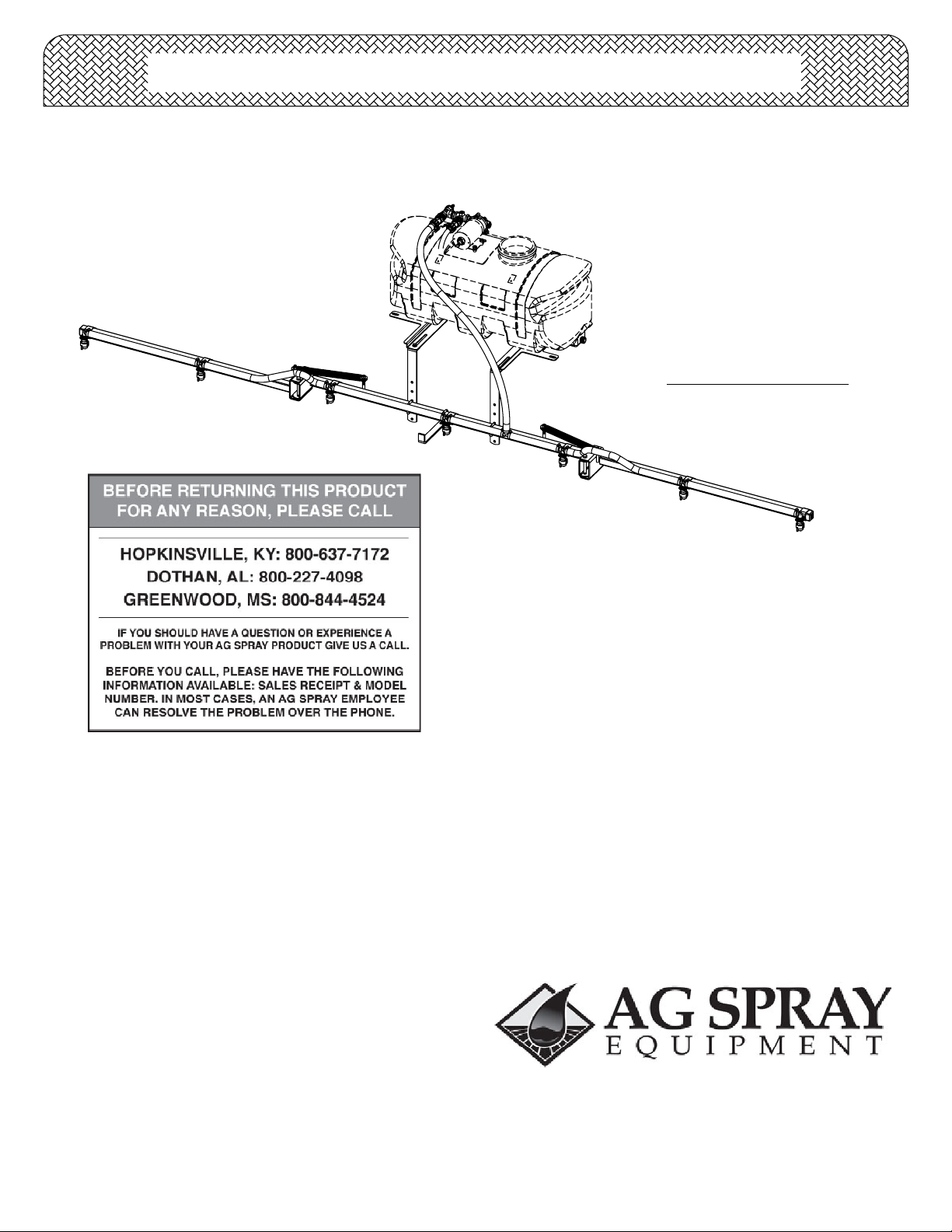
(7-Nozzle Boom Assembly with Brackets/Hardware & Connecting Fittings)
NOTE:
Tank & pump are shown, but
NOT included in this assembly.
Technical Specifications
7-Nozzle Boom Assembly
•
140" Spray Coverage
•
Corrosion-Resistant Nozzles
•
Mounting brackets/hardware
•
General Information
Thank you for purchasing this Ag Spray product. The purpose
of this manual is to assist you in operating and maintaining
your boom kit. Please read it carefully, as it furnishes
information which will help you achieve years of trouble-free
operation.
Warranty/Parts/Service
Products are warranted for one year from date of purchase
against manufacturer or workmanship defects.
Commercial users have a 90 day warranty.
Your authorized dealer is the best source of replacement parts
and service. To obtain prompt, efficient service, always
remember to give the following information...
Assembly
Remove the parts to the boom assembly from the
carton. Refer to the parts list and exploded view
drawing to help identify all the components.
1. Attach the tank to the brackets loosely.
2. Place the sprayer onto the carrier rack of the ATV.
Use the u-bolts and hardware to secure the tank mount
to the rack.
3. Connect the boom mounting brackets to the tank
mounting brackets with hardware provided as shown.
Note these brackets will be located about 16 1/4" apart
on most ATV's. Now tighten all bolts and nuts.
4. Center the center section of the boom onto your
boom mounts, and secure in place with the hardware
provided. Be sure that the outer booms will fold
'backwards'. The boom should be about 17"-19" above
the ground.
5. Attach the nozzle harness assembly to the boom.
6. Route your boom feeder hose to the back end of the
sprayer. Join the hose to the tee barb. Then clamp in
place with a hose clamp.
CAUTION: Never use a metal object or other sharp
item for cleaning a nozzle tip. It is better to use a
nozzle brush (NOT wire brush) or compressed air
for tip cleaning.
- Correct Part Description and/or part number.
- Model number/Serial number of your sprayer.
Part descriptions and part numbers can be obtained from the
illustrated parts list section(s) of this manual.
Whenever you need parts or repair service, contact your
distributor/dealer first. For warranty work, always take your
original sales slip, or other evidence of purchase date, to your
distributor/dealer.
www.agspray.com
1100 New Industry Lane
Hopkinsville, KY 42240
P: 800-637-7172
F: 270-885-7392
Form No. 1912 [5008225 (11/09)] Printed in the U.S.A.
104 Eastman Street
Greenwood, MS 38930
P: 800-844-4524
F: 662-455-4442
1563 S. Oates Street
Dothan, AL 36301
P: 800-227-4098
F: 334-673-1974
Testing the Sprayer
NOTE:
It is VERY important for you to test your sprayer with
plain water before actual spraying is attempted. This
will enable you to check the sprayer for leaks, without
the possibility of losing any expensive chemicals.
Add water to the tank & drive to the starting place for
spraying. When you are ready to spray, turn the boom
valve to the "on" position. This will start solution spraying
from the tips of the boom. The pressure will decrease
slightly when the boom is spraying. Adjust the pressure by
turning the "ON/OFF" valve lever on the bypass line valve.
Read the operating instructions, and Initially begin spraying
by closing the 'bypass' valve and opening the boom line
valve. This will enable the air in the line to be eliminated
(purged) through all the tips, while building pressure. When
everything tests all right (no leaks, & good pressure), add
the desired chemicals to the mixture and water
combination and start your spraying operation. Adjust the
pressure and spray as you did in the testing procedure.
Conditions of weather and terrain must be considered
when setting the sprayer. Do not spray on windy days.
Protective clothing must be worn in some cases.
Be sure to read the chemical label(s) correctly!
After Spraying
After use, fill the sprayer tank part way with water. Start the
sprayer, and allow the clear water to be pumped through
the plumbing system and out through the spray nozzles.
Refill the tank about half full with plain water and use a
chemical neutralizer, such as 'Nutra-Sol', or equivalent, and
repeat cleaning instructions above. A mix of water and
some detergent, such as 'Dawn' dish soap would be a
sufficient alternative.
Flush the entire sprayer with the neutralizing/cleaning
agent, then flush out one more time with plain water. Follow
the chemical manufacturer's disposal instructions of all
wash or rinsing water.
For the boom, (if applicable) remove the tips and screens
from the nozzle assemblies. Wash these items out
thoroughly. Blow the orifice clean and dry. If the orifice
remains clogged, clean it with a fine bristle (NOT WIRE)
brush, or with a toothpick. Do not damage the orifice. Water
rinse and dry the tips before storing.
WARNING: Some chemicals will damage the pump
valves if allowed to soak untreated for a length of time!
ALWAYS flush the pump as instructed after each use.
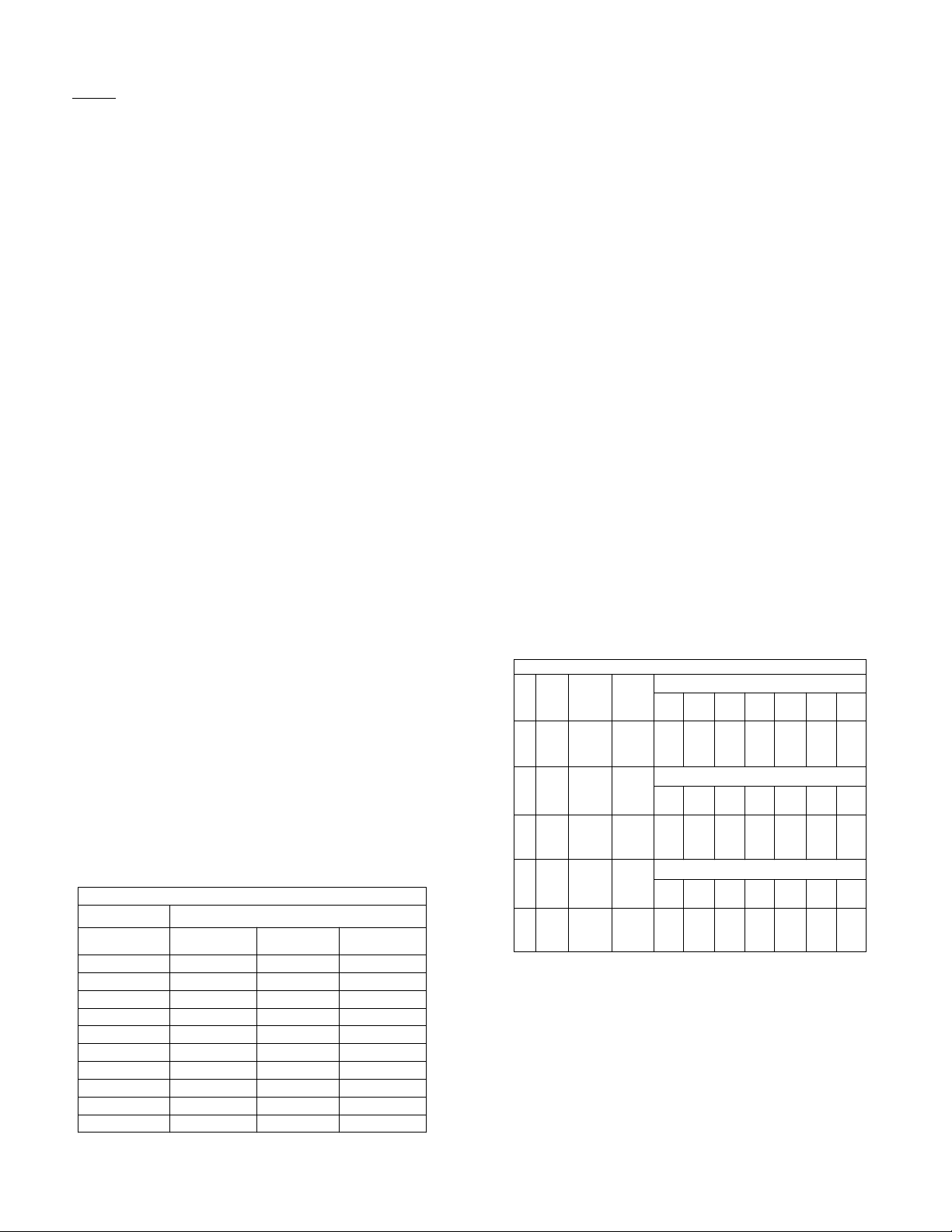
Speed Chart
Time Required in seconds to travel a distance of:
Speed in M.P.H.
(Miles per Hour)
1.0
2.0
3.0
4.0
5.0
6.0
7.0
8.0
9.0
10.0
100 Ft.
68 sec.
34
23
17 34
14
11
9.7
8.5
7.6
6.8
200 Ft.
136 sec.
68
45
27
23
19
17
15
14
300 Ft.
205 sec.
102
68
51
41
34
29
26
23
20
Calibration
Chemical labels may show application rates in gallons per
acre, gallons per 1000 square feet, or gallons per 100
square feet. You will note that the tip chart shows all 3 of
these rating systems.
Once you know how much you are going to spray, then
determine (from the tip chart) the spraying pressure (PSI),
and the spraying speed (MPH).
Determining the proper speed of the pulling vehicle can be
done by marking off 100, 200, & 300 feet. The speed chart
indicates the number of seconds it takes to travel the
distances. Set the throttle and with a running start, travel the
distances. Adjust the throttle until you travel the distances in
the number of seconds indicated by the speed chart. Once
you have reached the throttle setting needed, mark the
throttle location so you can stop and go again, returning to
the same speed.
Add water and proper amount of chemical to the tank and
drive to the starting place for spraying.
Winter Storage
Drain all water out of your sprayer, paying special attention
to the pump, handgun, and valve(s). These items are
especially prone to damage from chemicals and freezing
weather.
The sprayer should be winterized before storage by pumping
a solution of RV antifreeze through the entire plumbing
system. This antifreeze solution should remain in the
plumbing system during the winter months. When spring
time comes and you are preparing your sprayer for the spray
season, rinse the entire plumbing system out, clearing the
lines of the antifreeze solution. Proper care and maintenance
will prolong the life of your sprayer.
Rate Chart for 8002 Spray Tip
Tip
No.
Tip
No.
Tip
No.
2
2
2
Spray
Height
18"
Spray
Height
18"
Spray
Height
18"
Pressure
(psi)
20
30
40
50
Pressure
(psi)
20
30
40
50
Pressure
(psi)
20
30
40
50
Gallons Per Acre - Based on Water
Capacity
(GPM)
Capacity
(GPM)
Capacity
(GPM)
1
MPH
41.8
.14
51.2
.17
59.2
.20
Gallons Per 1000 Sq. Ft. - Based on Water
1
MPH
.96.14
1.18
.17
1.36
.20
1.52
.23
Gallons Per 100 Sq. Ft. - Based on Water
1
MPH
.14
.096
.17
.118
.136.20
.23 .152
MPH
20.9
25.6
29.6
MPH
.48
.59
.68
.76
MPH
.048
.059
.068
.076
3 2
MPH
MPH
14.0
10.5
12.9
17.2
14.9
19.8
16.622.233.266.4.23
3 2
MPH
MPH
.39
.45
.51
3 2
MPH
MPH
.024
.032
.030
.039
.034.045
.051 .038
.24.32
.30
.34
.38
4
4
4
7.5 5
MPH
MPH
8.4
5.6
10.3
6.9
11.9
7.9
7.5
MPH5 MPH
.13.19
.24
.16
.27
.18
.20
.31
7.5
5
MPH
MPH
.013
.019
.016
.024
.018.027
.031 .020
10
MPH
4.2
5.1
5.9
6.68.813.3
10
MPH
.10
.12
.14
.15
10
MPH
.010
.012
.014
.015
Page 2
 Loading...