

Owner's Manual
Boom Assemblies (with Carrier Support)
6-Row Boom Assembly
w/QJ Nozzles
8-Row Boom Assembly
w/QJ Nozzles
General Information
Thank you for purchasing this Ag Spray product. The
purpose of this manual is to assist you in operating and
maintaining your boom assembly. Please read it carefully,
as it furnishes information which will help you achieve
years of trouble-free operation.
Warranty/Parts/Service
Products are warranted for one year from date of purchase
against manufacturer or workmanship defects.
Commercial users have a 90 day warranty.
Your authorized dealer is the best source of replacement parts
and service. To obtain prompt, efficient service, always
remember to give the following information...
- Correct Part Description and/or part number.
- Model number/Serial number of your sprayer.
Part descriptions and part numbers can be obtained from the
illustrated parts list section(s) of this manual.
Whenever you need parts or repair service, contact your
distributor/dealer first. For warranty work, always take your
original sales slip, or other evidence of purchase date, to your
distributor/dealer.
Technical Specifications
Model
BA6D
•
(6 Row - 21 Ft. Wide)
Model
•
(8 Row - 28 Ft. Wide)
All Models:
•
- Adjustable Spacing Nozzles
•
- Height Adjustment
•
- 4-Way Hinge for Boom Protection
•
- Cross-Over Folding
•
- Tips/Caps/Strainers are Standard
•
- Fits all Various Carriers
•
- Square Boom Tube Construction
•
www.agspray.com
1100 New Industry Lane
Hopkinsville, KY 42240
P: 800-637-7172
F: 270-885-7392
Form No. 1916 [5008228 (11/09)] Printed in the U.S.A.
Boom Assembly
BA8D
Boom Assembly
104 Eastman Street
Greenwood, MS 38930
P: 800-844-4524
F: 662-455-4442
1563 S. Oates Street
Dothan, AL 36301
P: 800-227-4098
F: 334-673-1974

Assembly
Calibration
1. Mount the upright angles to the inside of the mounts on the
carrier, using the supplied bolts/nuts. Attach the backrack to the
upright angles using the square u-bolts & nuts. NOTE: The
backrack can be mounted in either a high or low position and the
uprights can be adjusted for desired height. Attach the UBrackets as shown in the exploded view drawing.
2. Loosen the eye-bolts and remove the 7" hinge bolt(s). Line up
the outer booms and reassemble the hinge bolt through the outer
boom yoke, the hinge casting, and the spring connector. Tighten
the eye-bolt until the spring is at the desired tension. Lock the
eye-bolt in place with the inner whiz flange locknut. The 8-Row
booms use extensions on the outer booms. Bolt on the boom
extensions using the bolts/nuts provided. (see exploded view
drawing)
3. Hook an end of each boom chain on an "S" hook attached to
the top bar tube. Place a slide clamp onto each outer boom.
Place the other end of the boom chain between the ears of the
slide clamp and secure with the bolt/nut per the exploded view.
Level the outer booms by moving the slide clamps in or out as
needed. Tighten the bolts in the slide clamps to hold the clamps
in place.
4. Attach the appropriate hose assemblies onto each of the three
boom sections. the center section has (5) nozzles with "L"
connectors on each end. Starting at the center, the nozzles
should be placed about 20 inches apart.
5. Join the designated feeder hose to each boom section and
secure in place with hose clamps.
Tip Selection
Important note:
The tips supplied as standard with this boom assembly are
number 8003VP tips. when you refer to the rate charts found in
this owners manual, you will note that they have a GPA range of
15.4 to 22 GPA (Gallons Per Acre). This is tabulated at 5 MPH,
and from 30 to 60 psi and 20 inch nozzle spacing. These rates
are based on water. Please read this tip selection section
carefully before attempting to operate your boom assembly
The selection of proper tips for the boom is determined by the
gallon per acre (GPA) requirement which is specified on the
chemical label. The following characteristics also have a
determining factor and must be considered:
Chemical labels may show application rates in gallons per
acre, gallons per 1000 square feet, or gallons per 100
square feet. You will note that the tip chart shows all 3 of
these rating systems.
Once you know how much you are going to spray, then
determine (from the tip chart) the spraying pressure (PSI),
and the spraying speed (MPH).
Determining the proper speed of the pulling vehicle can be
done by marking off 100, 200, & 300 feet. The speed chart
indicates the number of seconds it takes to travel the
distances. Set the throttle and with a running start, travel the
distances. Adjust the throttle until you travel the distances in
the number of seconds indicated by the speed chart. Once
you have reached the throttle setting needed, mark the
throttle location so you can stop and go again, returning to
the same speed.
Add water and proper amount of chemical to the tank and
drive to the starting place for spraying.
Testing the Sprayer
NOTE:
It is VERY important for you to test your sprayer with
plain water before actual spraying is attempted. This will
enable you to check the sprayer for leaks, without the
possibility of losing any expensive chemicals.
Add water to the tank & drive to the starting place for
spraying. When you are ready to spray, turn the boom valve
to the "on" position. This will start solution spraying from the
tips of the boom. The pressure will decrease slightly when the
boom is spraying. Adjust the pressure by turning the
"ON/OFF" valve lever on the bypass line valve.
Read the operating instructions and Initially begin spraying by
closing the 'bypass' valve (this is the center ON/OFF valve
located at the center port of your manifold assembly) and
opening the boom line valve (this is the 'other' valve on the
manifold). This will enable the air in the line to be eliminated
(purged) through all the tips, while building pressure. When
everything tests all right (no leaks, & good pressure), add the
desired chemicals to the mixture and water combination and
start your spraying operation. Adjust the pressure and spray
as you did in the testing procedure.
Speed of spraying (MPH)
1.
Boom nozzle spacing (specified in inches)
2.
Solution weight and conversion factor (CF)
3.
Gallons of solution to be sprayed per acre
4.
Spraying pressure
5.
Useful Formulas:
GPM - Gallons Per Minute
GPA - Gallons Per Acre
MPH - Miles Per Hour
Speed Chart
Time Required in seconds to travel a distance of:
100 Ft.
68 sec.
34
23
17 34
14
11
9.7
8.5
7.6
6.8
200 Ft.
136 sec.
Page 2
Speed in M.P.H.
(Miles per Hour)
1.0
2.0
3.0
4.0
5.0
6.0
7.0
8.0
9.0
10.0
Conditions of weather and terrain must be considered when
setting the sprayer. Do not spray on windy days. Protective
clothing must be worn in some cases.
Be sure to read the chemical label(s) correctly!
Suggested Minimum Spray Heights
Nozzle Height
Nozzle Type
300 Ft.
68
45
27
23
19
17
15
14
205 sec.
102
68
51
41
34
29
26
23
20
TeeJet (Flat Spray)
TeeJet (XR TeeJet)
TeeJet (XR TeeJet)
FloodJet
* Not Recommended
*** Wide angle spray tip is influenced by nozzle orientation
The critical factor is to achieve a double spray pattern overlap.
Spray
Angle
65
80
110
120
20"
Spacing
°
22"-24"
°
17"-19"
°
12"-14"
*** ***
°
30"
Spacing
33"-35"
26"-28"
16"-18"
***
40"
Spacing
NR*
NR*
NR*
Nozzle Spacing
If the nozzle spacing on your boom is different
from those tabulated, multiply the tabulated
GPA coverage by one of the following factors.
Where Tables are Based on 20" Nozzle Spacing
Other Spacing
Conversion
Factor
8"
2.5
1.67
1.43
1.25
18"10" 12" 16"14" 30"22" 24"
1.11
.91
.83
.66
Where Tables are Based on 30" Nozzle Spacing
Other Spacing
Conversion
Factor
26"
1.15
28"232"
1.07
.94
34"
.88
36"
.83
38"
.79
40"
.75
42"
.71
44"
.68
Where Tables are Based on 40" Nozzle Spacing
Other Spacing
Conversion
Factor
28"
1.43
30"
1.33
32"
1.25
34"
1.18
36"
1.11
38"
1.05
42"
.95
44"
.91
48"
.83
Spraying Solutions Other Than Water
Flow Rate
Nozzle flow rate varies with spraying pressure. In general,
the relationship between GPM and pressure is as follows:
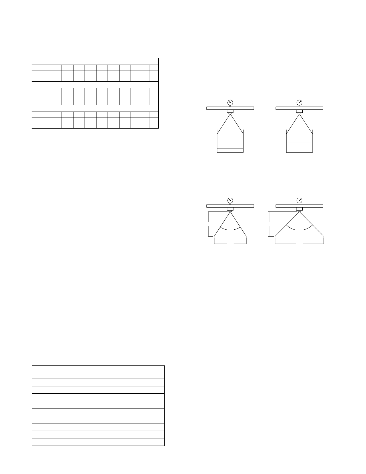
This equation is explained by the illustration below. Simply
stated, to double the flow through a nozzle, the pressure be
increased four times.
Effect of Pressure on Volume
8002
@ 10 psi @ 40 psi
8002
Since all the tabulations are based on spraying water, which
weighs 8.34 lbs per USA gallon, conversion factors must be
used when spraying solutions which are heavier or lighter than
water. To determine the proper size nozzle for the solution to be
sprayed, first multiply the desired GPM or GPA of solution by
the rate conversion factor. Then use the new converted GPM or
GPA rate to select the proper size nozzle.
Example:
Desired application rate is 20 GPA of 28% Nitrogen.
Determine the correct nozzle size as follows:
GPA (Solution) x Conversion Factor = GPA
20 GPA (28%) x 1.13 = 22.6 GPA (Water)
The applicator should choose a nozzle size that will supply 22.6
GPA of water at the desired pressure.
Miscellaneous Conversion Factors
One Acre = 43,560 square feet = 0.405 Hectacre
One Hectacre = 2.471 Acres
One Gallon Per Acre = 9.35 Liters Per Hectacre
One Mile = 5280 Feet = 1610 Meters = 1.61 Kilometers
One Gallon = 128 Fluid Ounces = 8 Pints = 4 Quarts = 3.79
Liters = 0.83 Imperial Gallons
One Pound Per Square Inch = 0.069 bar. = 6.895 Kilo-Pascals
One Mile Per Hour = 1.609 Kilometers Per Hour
Higher pressure not only increases the flow rate of the nozzle,
but it also influences the droplet size and the rate of orifice
wear. As pressure is increased, the droplet size decreases
and the rate of orifice wear is increased.
The values given in the tabulation section of this owners
manual indicate the most commonly used pressure ranges for
the associated spray tips.
Weight of Solution
7.0 lbs per gallon
8.0 lbs per gallon
8.834 lbs per gallon (Water)
9.0 lbs per gallon
10.0 lbs per gallon
10.65 lbs per gallon (28% Nitrogen)
11.0 lbs per gallon
12.0 lbs per gallon
14.0 lbs per gallon
Specific
Gravity
.84 .92
.96 .98
1.00 1.00
1.08 1.04
1.20 1.10
1.28 1.13
1.32 1.15
1.44 1.20
1.68 1.30
Conversion
Factors
0.1 gpm 0.2 gpm
Effect of Pressure on Spray Angle
8002 8002
18"
@ 15 psi
18"
60°
23"
@ 40 psi
80°
30"
Higher pressure not only increases the flow rate of the
nozzle, but it also influences the droplet size and the rate of
orifice wear. As pressure is increased, the droplet size
decreases, and the rate of orifice wear is increased.
The values given in the tabulation section of this owner's
manual indicate the most commonly used pressure ranges
for the associated spray tips.
Spray Angle and Coverage
Depending on the nozzle type and size, the operating
pressure can have a significant effect on spray angle and
quality of spray distribution. As shown above for an 8002 flat
spray tip, lowering the pressure results in a smaller spray
angle and a significant reduction in spray coverage.
Tabulations for spray tips shown in this owner's manual are
based on spraying water. Generally, liquids more viscous
than water form relatively smaller spray angles. Whereas,
liquids with surface tensions lower than water will produce
wider spray angles. In situations where the uniformity of
spray distribution is important, be careful to operate your
spray tips within the proper pressure range.
NOTE: Suggested minimum spray heights for broadcast
spraying are based upon nozzles spraying water at the
rated spray angle.
Page 3

After Spraying
Winter Storage
After use, fill the sprayer tank part way with water. Start the
sprayer, and allow the clear water to be pumped through the
plumbing system and out through the spray nozzles.
Refill the tank about half full with plain water and use a chemical
neutralizer, such as 'Nutra-Sol', or equivalent, and repeat
cleaning instructions above. A mix of water and some detergent,
such as 'Dawn' dish soap would be a sufficient alternative.
Flush the entire sprayer with the neutralizing/cleaning agent,
then flush out one more time with plain water. Follow the
chemical manufacturer's disposal instructions of all wash or
rinsing water.
For the boom, (if applicable) remove the tips and screens from
the nozzle assemblies. Wash these items out thoroughly. Blow
the orifice clean and dry. If the orifice remains clogged, clean it
with a fine bristle (NOT WIRE) brush, or with a toothpick. Do not
damage the orifice. Water rinse and dry the tips before storing.
WARNING: Some chemicals will damage the pump valves if
allowed to soak untreated for a length of time! ALWAYS
flush the pump as instructed after each use.
Drain all water out of your sprayer, paying special attention to
the pump, handgun, and valve(s). These items are especially
prone to damage from chemicals and freezing weather.
The sprayer should be winterized before storage by pumping a
solution of RV antifreeze through the entire plumbing system.
This antifreeze solution should remain in the plumbing system
during the winter months. When spring time comes and you
are preparing your sprayer for the spray season, rinse the
entire plumbing system out, clearing the lines of the antifreeze
solution. Proper care and maintenance will prolong the life of
your sprayer.
Page 4

8.16
8.7
8.4
8.11
3
2
3
6
4
1
2
Back Rack
(w/Vertical Mounts)
5
Item NoFIMCO Part
Number
1
5006307
2
5022238
3
5038317
4
5101065
5
5101231
6
5117300
7
5275256
7.1 5022255 1
7.2 5006337 2
7.3 5006307 4
7.4 5034159 2
7.5 5034019 2
Center Rack
8
Assembly
8.1 5006054 4
8.2 5006091 4
8.3 5006142 2
8.4 5006307 8
8.5 5034074 2
8.6 5034107 2
8.7 5034159 4
8.8 5034308 4
8.9 5273315 1
8.10 5009635 1
8.11 5022256 2
8.12 5080012 2
8.13 5080011 2
8.14 5271580 2
8.15 5019097 2
8.16 5082006 2
8.4
Qty
Description
2
5/16"-18 Hex Whiz (Flange) Locknut
2
Mounting Angle
2
U-Bracket
2
Hair-Pin Cotter (0.120" Dia.)
2
Pin
2
5/16"-18 x 1" Flange Whiz Lock Screw
2
Upright Assembly
Boom Mounting Angle
1/2"-13 Hex Whiz (Flange) Locknut
5/16"-18 Hex Whiz (Flange) Locknut
Square U-Bolt, 5/16" x 1 5/16" x 1 7/8"
H.H.C.S., 1/2"-13 x 1 1/4"
1
BA6D & BA8D Boom Center Section
3/8"-16 Hex Nut
1/2"-13 Hex Locknut
Hex Jam Locknut, 1/2"
5/16"-18 Hex Whiz (Flange) Locknut
H.H.C.S., 1/2"-13 x 7"
3/8" x 4" Eyebolt, Turned, Zinc-Plated
Square U-Bolt, 5/16" x 1 5/16" x 1 7/8"
H.H.C.S., 1/2"-13 x 2 1/4"
Center Boom Weldment
Top Bar Tube (257 Boom)
End Angle (257 Boom)
Center Hinge Section
Outer Hinge Section
Spring Connector Weldment
Hinge Spring
"S" Hook
List
Price
.25
3.10
7.64
.40
3.50
.22
27.50
17.60
.30
.25
.65
.48
.25
.25
.25
.25
1.90
1.52
.65
.68
63.57
15.78
5.11
12.45
18.93
6.75
3.50
.55
8.10
7.4
8.7
7.1
8.9
8.11
8.4
7.4
7.2
7.5
8.1
8.6
8.15
8.2
NOTE:
Mounting angles (Item 2) are used when the boom
is positioned in the "high" position. Otherwise the Ubracket (Item 3) is bolted to the top holes in the upright
angle (Item 7.1).
8.4
8.5
8.16
8.8
8.12
8.13
8.3
8.14
Center "Back Rack" Mounted
in the "High" Position
3
2
3
2
Center "Back Rack" Mounted
in the "Low" Position
Mounting Angles are NOT Used
Mounting Angles ARE Used
Page 5

18
Model: BA6D (5301957)
7
14
22
16
7
20
Item NoFIMCO Part
Number
1 5006092 4 4
2 5006259 2 2
3 5006307 2 2
4 5022238 2 2
5 5034101 4 4
6 5038317 2 2
7 5049018 2 2
8 5051085 2 2
9 5101065 2 2
10 5101231 2 2
11 5117300 2 2
12 5117307 2 2
13 5272165 13 17
14 5273313 2 2
15 5275256 2 2
16 5275736
17 5277032 1 1
18 5277033 1
19 5277034 1
20 5277035
21 5277036
Center Rack
22
Assembly
BA6D
(5301957)/QTY.
-
-
-
1 1
BA8D
(5301958)/QTY.
Components and their quantities for the 'Center Rack Assembly'
& 'Upright Assembly' are called out on Page 5.
14
Description
3/8"-16 Hex Locknut
3/8"-16 Hex Whiz (Flange) Locknut
5/16"-18 Hex Whiz (Flange) Locknut
Mounting Angle
H.H.C.S., 3/8"-16 x 1 3/4"
U-Bracket
Boom Chain (7 Ft.)
Slide Clamp
Hair-Pin Cotter (0.120" Dia.)
Pin
5/16"-18 x 1" Flange Whiz Lock Screw
3/8"-16 x 1" Whiz (Flange) Lockscrew
Vari-Quick Clamp (1 1/4" Sq. Tube)
End Boom Weldment
Upright Assembly
2
Boom Extension (for 8-Row)
1/2" QJ Center Nozzle Harness
-
1/2" QJ (LH) Nozzle Harness (BA6D)
-
1/2" QJ (RH) Nozzle Harness (BA6D)
1
1/2" QJ (LH) Nozzle Harness (BA8D)
1
1/2" QJ (RH) Nozzle Harness (BA8D)
BA6D & BA8D Boom Center Section
15
17
17
22
List
Price
.25
.25
.25
3.10
.50
7.64
3.25
8.72
.40
3.50
.22
.46
2.57
38.16
27.50
14.50
14
7
19
Model: BA8D (5301958)
14
21
Typ. Boom Extension Attachment
7
14
1
5
(BA8D Boom)
7
12
14
F
16
13
16
2
8
Page 6
DETAIL F

BA6D (5301957) & BA8D (5301958) Nozzle Assemblies
4.2.1
4.2.2
4.2.3
4.2.4
4.2.5
5.1.1
5.1.2
5.1.3
5.1.4
5.1.5
Center Harness Assembly #5277032 (BA6D & BA8D Boom Assemblies)
1.5 1.5
LH Harness Assembly #5277033 (BA6D Boom)
2.2.1
2.2.3
2.2.5
2.2.2
2.2.4
2.3
RH Harness Assembly #5277034 (BA6D Boom)
3.1.1
3.1.3
3.1.5
3.1.2
3.1.4
3.3
LH Harness Assembly #5277035 (BA8D Boom)
4.3
4.3
RH Harness Assembly #5277036 (BA8D Boom)
5.3
5.3 5.3
1.4
2.3
3.3
4.3
1.3 1.4
2.4
3.4
4.4
5.4
3.3
2.3
4.3
5.3
1.1.1
1.1.2
1.1.3
1.1.4
1.1.5
2.1.1
2.1.2
2.1.3
2.1.4
2.1.5
3.2.1
3.2.2
3.2.3
3.2.4
3.2.5
1.5
5.3
4.3
1.6
1.2.1
1.2.2
1.2.3
1.2.4
1.2.5
4.1.1
4.1.2
4.1.3
4.1.4
4.1.5
5.2.1
5.2.2
5.2.3
5.2.4
5.2.5
Item
No
1
1.1
1.1.1
1.1.2
1.1.3
1.1.4
1.1.5
1.2
1.2.1
1.2.2
1.2.3
1.2.4
1.2.5
1.3
1.4
1.5
1.6
2
2.1
2.1.1
2.1.2
2.1.3
2.1.4
2.1.5
2.2
2.2.1
2.2.2
2.2.3
2.2.4
2.2.5
2.3
2.4
3
3.1
3.1.1
3.1.2
3.1.3
3.1.4
3.1.5
FIMCO Part
Number
5277032
5277031
5056067
5116019
5016157
5018266
5046219
5277030
5056065
5116019
5016157
5018266
5046219
5086003
5020144
5020416
5051114
5277033
5277031
5056067
5116019
5016157
5018266
5046219
5277030
5056065
5116019
5016157
5018266
5046219
5020416
5051114
5277034
5277031
5056067
5116019
5016157
5018266
5046219
Description
Qty
1
1/2" QJ Center Nozzle Harness
3
1/2" TEE QJ Nozzle Assembly
1
Double Hose Shank (1/2" Hose)
1
50 Mesh Nozzle Strainer, Red
1
Seat Washer
1
Flat Spray Tip, Blue
1
Quick TeeJet Cap (Yellow)
2
1/2" ELL QJ Nozzle Assembly
1
Single Hose Shank (1/2" Hose)
1
50 Mesh Nozzle Strainer, Red
1
Seat Washer
1
Flat Spray Tip, Blue
1
Quick TeeJet Cap (Yellow)
1
Nylon Hose Tee, 1/2" HB
2
Hose, 1/2"-1 Brd. x 10"
3
Hose, 1/2"-1 Brd. x 19 3/8"
10
Hose Clamp, 3/8"
1
1/2" QJ (LH) Nozzle Harness
3
1/2" TEE QJ Nozzle Assembly
1
Double Hose Shank (1/2" Hose)
1
50 Mesh Nozzle Strainer, Red
1
Seat Washer
1
Flat Spray Tip, Blue
1
Quick TeeJet Cap (Yellow)
1
1/2" ELL QJ Nozzle Assembly
1
Single Hose Shank (1/2" Hose)
1
50 Mesh Nozzle Strainer, Red
1
Seat Washer
1
Flat Spray Tip, Blue
1
Quick TeeJet Cap (Yellow)
3
Hose, 1/2"-1 Brd. x 19 3/8"
6
Hose Clamp, 3/8"
1
1/2" QJ (RH) Nozzle Harness
3
1/2" TEE QJ Nozzle Assembly
1
Double Hose Shank (1/2" Hose)
1
50 Mesh Nozzle Strainer, Red
1
Seat Washer
1
Flat Spray Tip, Blue
1
Quick TeeJet Cap (Yellow)
List
Price
3.84
1.05
.40
.84
.61
3.84
1.05
.40
.84
.61
.88
1.77
2.17
.63
3.84
1.05
.40
.84
.61
3.84
1.05
.40
.84
.61
2.17
.63
3.84
1.05
.40
.84
.61
Item
No
3.2
3.2.1
3.2.2
3.2.3
3.2.4
3.2.5
3.3
3.4
4
4.1
4.1.1
4.1.2
4.1.3
4.1.4
4.1.5
4.2
4.2.1
4.2.2
4.2.3
4.2.4
4.2.5
4.3
4.4
5
5.1
5.1.1
5.1.2
5.1.3
5.1.4
5.1.5
5.2
5.2.1
5.2.2
5.2.3
5.2.4
5.2.5
5.3
5.4
FIMCO Part
Number
5277030
5056065
5116019
5016157
5018266
5046219
5020416
5051114
5277035
5277031
5056067
5116019
5016157
5018266
5046219
5277030
5056065
5116019
5016157
5018266
5046219
5020416
5051114
5277036
5277031
5056067
5116019
5016157
5018266
5046219
5277030
5056065
5116019
5016157
5018266
5046219
5020416
5051114
Description
Qty
1
1/2" ELL QJ Nozzle Assembly
1
Single Hose Shank (1/2" Hose)
1
50 Mesh Nozzle Strainer, Red
1
Seat Washer
1
Flat Spray Tip, Blue
1
Quick TeeJet Cap (Yellow)
3
Hose, 1/2"-1 Brd. x 19 3/8"
6
Hose Clamp, 3/8"
1
1/2" QJ (LH) Nozzle Harness (BA8D)
5
1/2" TEE QJ Nozzle Assembly
1
Double Hose Shank (1/2" Hose)
1
50 Mesh Nozzle Strainer, Red
1
Seat Washer
1
Flat Spray Tip, Blue
1
Quick TeeJet Cap (Yellow)
1
1/2" ELL QJ Nozzle Assembly
1
Single Hose Shank (1/2" Hose)
1
50 Mesh Nozzle Strainer, Red
1
Seat Washer
1
Flat Spray Tip, Blue
1
Quick TeeJet Cap (Yellow)
5
Hose, 1/2"-1 Brd. x 19 3/8"
10
Hose Clamp, 3/8"
1
1/2" QJ (RH) Nozzle Harness (BA8D)
5
1/2" TEE QJ Nozzle Assembly
1
Double Hose Shank (1/2" Hose)
1
50 Mesh Nozzle Strainer, Red
1
Seat Washer
1
Flat Spray Tip, Blue
1
Quick TeeJet Cap (Yellow)
1
1/2" ELL QJ Nozzle Assembly
1
Single Hose Shank (1/2" Hose)
1
50 Mesh Nozzle Strainer, Red
1
Seat Washer
1
Flat Spray Tip, Blue
1
Quick TeeJet Cap (Yellow)
5
Hose, 1/2"-1 Brd. x 19 3/8"
10
Hose Clamp, 3/8"
List
Price
3.84
1.05
.40
.84
.61
2.17
.63
3.84
1.05
.40
.84
.61
3.84
1.05
.40
.84
.61
2.17
.63
3.84
1.05
.40
.84
.61
3.84
1.05
.40
.84
.61
2.17
.63
Page 7
 Loading...