

Page 1
DirectCommand
Norac UC5
TM
Setup UC5
Automatic
Setup
Sensors and
Valve Drivers
Boom Control
Module
Advanced
Settings
Retune
Norac UC5
Controller #300
Firmware Version Unknown
Hardware Version Unknown
Sprayer Conguration Sprayer Model 1
Conguration Product
Application
Press to Highlight Conguration
4930rx
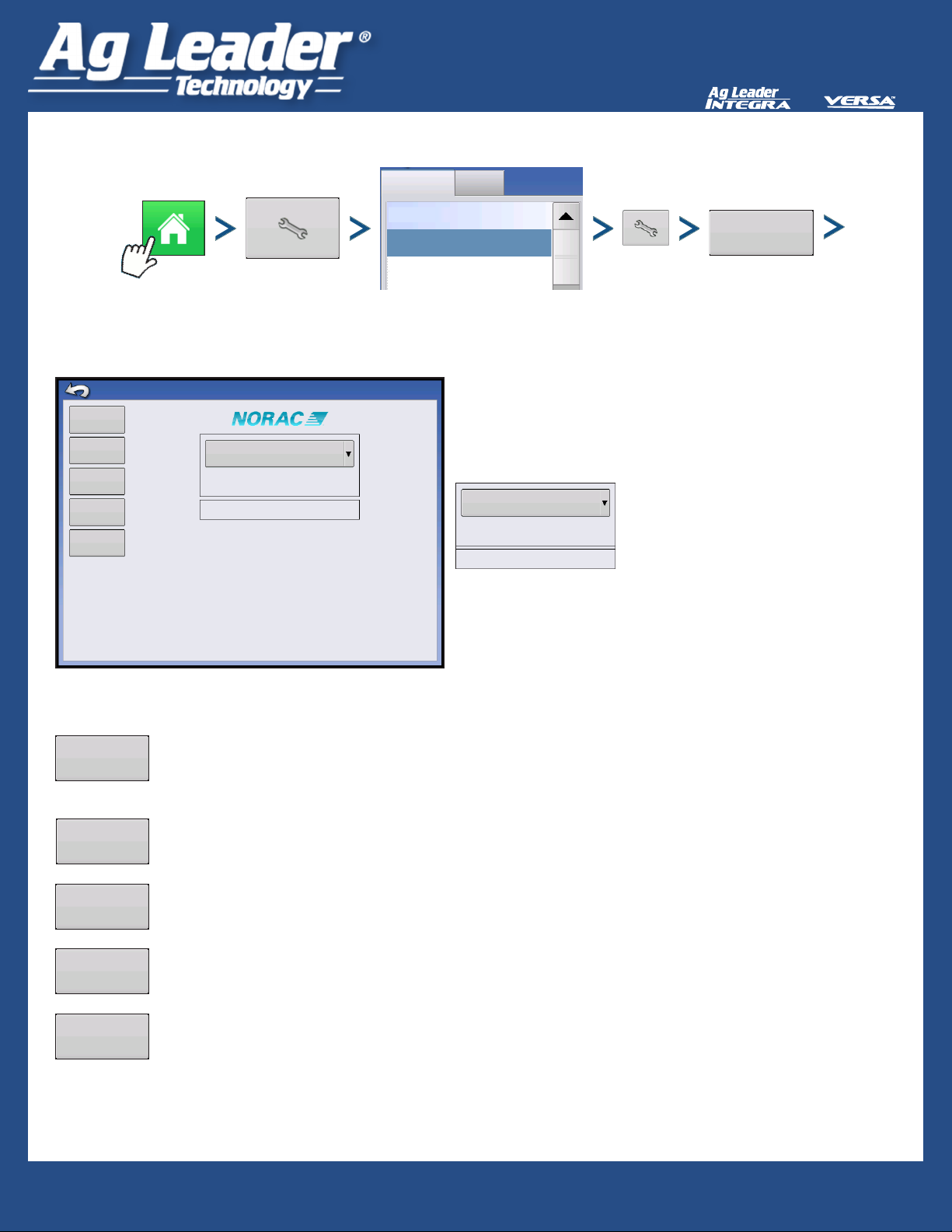
Norac Devices drop-down menu
Controller #300
Firmware Version Unknown
Hardware Version Unknown
Sprayer Conguration Sprayer Model 1
Norac
UC5
shows devices communicating
on NORAC UC5 CAN Bus
Firmware Version and Hardware
Revisions shown underneath
Automatic
Setup
Sensors and
Valve Drivers
Boom Control
Module
Advanced
Settings
Retune
Automatic Setup
steps that congure the NORAC system with the sprayer hydraulic functions must perform
this routine after system is installed
Sensors and Valve Drivers
setup of sensors and valve (explained on next page)
Boom Control Module tab
turn motion detection on/off, choose source as GPS or Aux.
Advanced Settings tab
NORAC non-user menu, password required.
Retune tab
recalibrates hydraulic settings and boom geometry
Quick Reference Guide
PN ?????? Rev A
AL: 2006313 - ENG Rev C
PN 2006313 Rev A
1
1
Page 2
DirectCommand
Norac UC5
TM
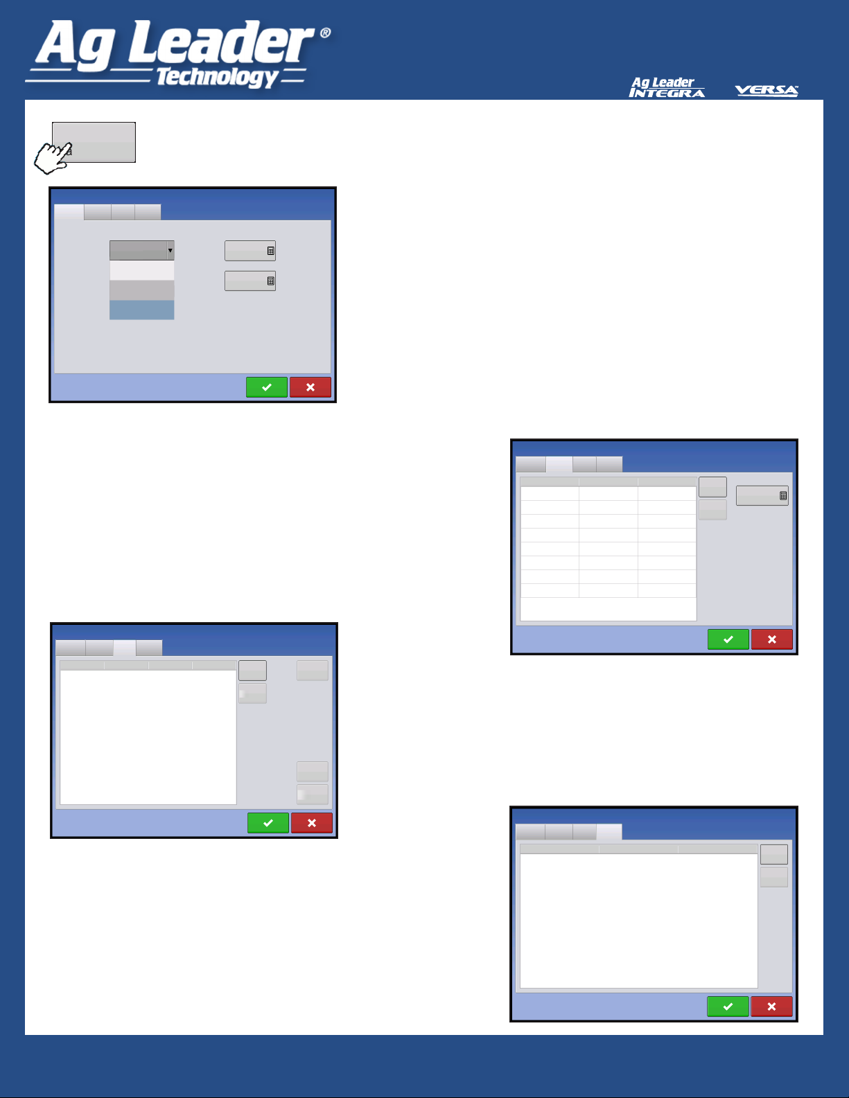
Sensors and
Sensors and Valve Drivers
Valve Drivers
General Tab
Minimum Height Mode:
Absolute - no sensors allowed to move closer to target
than minimum height setting
Relative - no sensors allowed to move closer to the
target than distance of the target height minus the
minimum height setting.
Disabled - disables minimum height mode
General
Sensor
Minimum Height Mode
Absolute
Disabled
Relative
Absolute
Norac UC5 Setup
SwitchValve
Minimum Height
Soil Mode
24 in
Crop Mode
24 in
Target: Soil Mode= ground, Crop Mode=crop
canopy.
Minimum Height:
Soil Mode - minimum height setting in Soil Mode
Crop Mode - minimum height setting in Crop Mode.
Sensor tab
list of each sensor type and serial number, add or remove
a sensor, input nozzle height
Norac UC5 Setup
General
Sensor
Type Sensor Serial Number
Height Left Outer 100
Height Main Lift 101
Height Right Outer 102
Height Left Inner 103
Height Right Inner 104
Roll Boom Frame 105
Roll Intermediate Frame 106
Roll Reference Frame 107
SwitchValve
Add
Remove
Nozzle Height
0
Norac UC5 Setup
General
Sensor
Valve Type Serial Output
Left Up Valve 200 2
Left Down Valve 200 3
Right Up Valve 200 4
Right Down Valve 200 5
Main Up Valve 200 6
Main Down Valve 200 7
Roll Up Valve 200 8
Roll Down Valve 200 9
Bypas Valve 200 1
SwitchValve
Add
Remove
Test
Valve
Valve tab
list of each valves, type, serial number, and output
add or remove a valve, test valve, adjust gain and deadzone
Gain
Deadzone
Switch tab
list of switches, function, serial number, and input
add or remove a switch.
Norac UC5 Setup
General
Sensor
Function Serial Input
Left Up 108 1
Left Down 108 2
Right Up 108 3
Right Down 108 4
Main Up 108 5
Main Down 108 6
Roll Up 108 7
Roll Down 108 8
SwitchValve
Add
Remove
Quick Reference Guide
PN ?????? Rev A
AL: 2006313 - ENG Rev C
PN 2006313 Rev A
2
2
Page 3

Load Conguration
Engage button enables boom height control.
When enabled button turns green and display beeps three times.
When disabled button turns white and display beeps twice.
Start Field Operation
Run Screen
DirectCommand
Norac UC5
TM
Mode: Crop
8.0 50 F13.1
Boom Height Control Options Button
White Arrows
direction boom section is moving
Mode
Crop Mode or Soil Mode
Target Height - desired boom height:
Soil Mode - distance above ground
Crop Mode - distance above crop canopy
Sensitivity
higher values make height control more responsive
9.2
Sensitivity: 5Target Height: 12 in
Distance Between Boom and Target
distance between boom and target
Temperature
air temperature
Quick Reference Guide
PN ?????? Rev A
AL: 2006313 - ENG Rev C
PN 2006313 Rev A
3
3
Page 4

DirectCommand
Norac UC5
TM
Mode: Crop
Boom Height Diagnostics
Target Height: 12 in
8.0 50 F
9.2
Sensitivity: 5
13.1
Boom Height Control Options Screen
Mode
Crop Mode or Soil Mode
Crop Mode
Target Height
desired boom height:
Target HeightSensitivity
12
5
Sensitivity
higher values make height control more responsive
Settings range from 0-10
Soil Mode - distance above ground
Crop Mode - distance above crop canopy
CAN A
Boom Height Diagnostics
Control Mode
Target Height (cm)
Remote Switch
1 Left Outer 100 0 cm 21.1 C
2 Left Inner 103 0 cm 21.1 C
3 Main Lift 101 0 cm 21.1 C
4 Right Inner 104 0 cm 21.1 C
5 Right Outer 102 0 cm 21.1 C
6 Boom Frame 105 0 cm N/A
7 Intermediate Frame 106 0 cm N/A
8 Reference Frame 107 0 cm N/A
General Boom Control State
Location Serial Height/Roll Temperature
Crop
30.4
Left
Center
Right
Roll
127 NORAC UC5
Automatic
Automatic
Automatic
Automatic
Boom Height Diagnostics
shows all data for individual sensors, including
height, roll, and temperature
Diagnostics
Quick Reference Guide
PN ?????? Rev A
AL: 2006313 - ENG Rev C
PN 2006313 Rev A
4
4
 Loading...