

Page 1
VT Quick Reference Guide
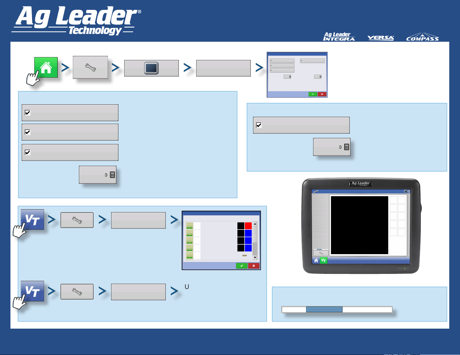
Enable Virtual Terminal
Virtual Teminal
Enable Virtual Terminal
Broadcast GPS Speed
Auxiliary Module Support
Functional Instance
Used to map implement
functions to OEM switches.
ISOBUS Settings
VT button appears in task bar once
button is checked.
Allows implement to use GPS ground
speed gathered by the display.
Assign implement functions to ISO
campatible inputs.
Always set to 0 except when there
are multiple VTs on the ISOBUS. Use
keypad to change instance. Reboot
display.
Auxiliary
Assignment
Function
VT Demo
VT Demo
VT Demo
VT Demo
VT Demo
Auxiliary Assignment
M
1
2
3
4
Virtual Terminal
Enable Virtual Terminal
Broadcast GPS Speed
Auxiliary Module Support
Function Instance
Task Controller
Enable Task Controller
Functional Instance
Input
Aux
M
Aux
F1
Aux
F2
F3
Aux
ISOBUS Settings
0
Task Controller
Enable Task Controller
Function Instance
0
Supported on compatible
equipment ECU’s.
Always set to 0 except when
there are multiple VTs on the
ISOBUS. Use keypad to change
instance. Reboot display.
Clear
Virtual Terminal
Used to clear object pools
from internal memory.
Status Bar
Quick Reference Guide
AL: 2006300 - ENG Rev C
Appears while Object Pool is in the
process of loading.
1
Page 2
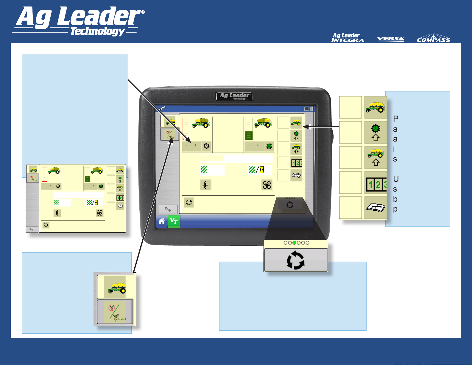
Object Pool
Graphical UI elements
sent by Working Set
Master (WSM) on rst
connection with VT.
Size is dependent on
complexity of module UI.
The Object Pool is stored
locally in VT display
memory.
0 . 0 0 . 0
50 . 0
Rate
98 . 5
1
ac
Command received. Front Meter
Clutch OFF!
a c / h r
0 . 0
74 . 0
r / min
l b s / acl b s / ac
0
VT Quick Reference Guide
Virtual Terminal Screen
0 . 0
lbs / ac
Rate
98 . 5
ac
Command received. Front Meter
Clutch OFF!
50 . 0
ac / hr
0 . 8
r / min
0 . 0
lbs / ac
74 . 0
8
Softkeys
Press to
access
and adjust
implement
settings.
Up to 10
softkeys can
be populated
per screen.
ISOBUS Working Set
One or more
ISOBUS
modules that
control an
implement’s
functionality.
Arrow Button
Advance through multiple screens of
Softkeys.
This button remains hidden unless
more than 10 softkeys are present.
Quick Reference Guide
AL: 2006300 - ENG Rev C
2
Page 3
VT Quick Reference Guide
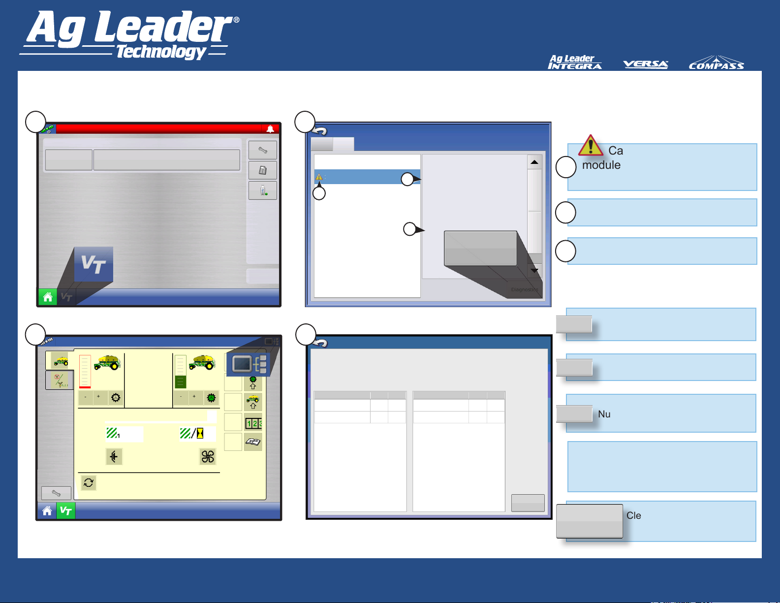
ISO Node Diagnostics
1
2
Conguration
Operator:
Virtual Terminal Alarm
Start Field Operation
0 . 0
lbs / ac
Rate
98 . 5
50 . 0
ac
Command received . Front Meter
Clutch OFF!
ac / hr
0 . 0
74 . 0
r / min
0
0 . 0
lbs / ac
11:37:10 AM
03/11/2011
3
CAN B
CAN A
233 ISO NODE
134 ISO NODE
A
4
ECU: 5000218*1547854*IMPLEMENT*VT MODULE*AG LEADER TECHNOLOGY*
Software ID: ALTECH, VT ODULE; 01.00.00.00;VT_MODULE_FW;01.00.00.00*
Active Errors:
SPN
522102
52366
FMI
12 12
3
Devices
CAN Name: 4E 9E 37OC OO
Self Congurable: Yes
Industry Group: Agriculture and Fo
B
Device Class: Sprayers
Device Class Instance: 0
Function: 128
Function Instance: 0
ECU Instance: 0
Identity Number: 1547854
Manufacturer Code: 97
C
Ag L
Firmwar
Firmwar
Diagnostics
Hardwar
Serial N
Revision:
ISO Node Diagnostics
Previously Active Errors:
522102
523666
SPN
FMI
3
OC OC
1
2 2
Caution Icon indicates
module has active trouble
A
codes (DTCs)
Equipment Type
B
ECU Manufacturer
C
SPN
FMI
1
OC
Clear Prev
Active Errors
Clear Prev
Active Errors
Suspect Parameter Number
Error Number
Fault Mode Indicator
Error State
Occurrence Count
Number of times error has occurred
Diagnostic Trouble Code (DTC)
This is SPN + FMI. Reference this
number in the implement owners
manual to diagnose error.
Clears previous active errors
from the history.
Quick Reference Guide
AL: 2006300 - ENG Rev C
3
Page 4
VT Quick Reference Guide
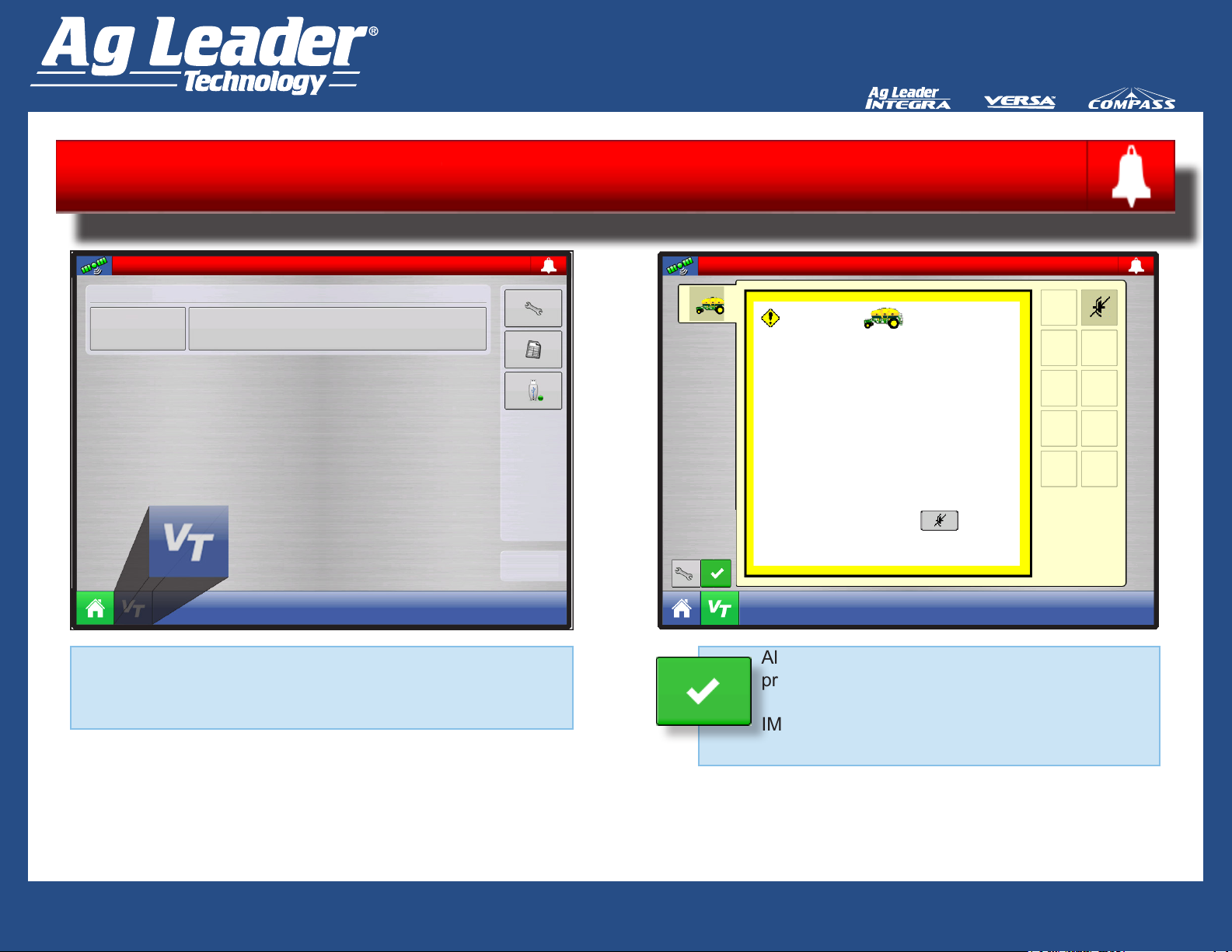
Virtual Terminal Alarm
Virtual Terminal Alarm
Conguration
Operator:
Start Field Operation:
11:37:10 AM
03/11/2011
When an alarm is activated on the VT, the display will
indicate the alarm by ashing “Virtual Terminal Alarm” in
the status bar.
Virtual Terminal Alarm
Low fan speed detected
Disable Main
Drive Shutoff
Alarms are acknowledged and cleared by
pressing the green check mark button.
IMPORTANT: This button is only present when
a virtual terminal alarm has been activated.
Quick Reference Guide
AL: 2006300 - ENG Rev C
4
Page 5
VT Quick Reference Guide
Connecting the System
Existing Tractor
ISOBUS
CAN B IN
CAN B OUT
Generic ISOBUS Installation
Display - Main
Power Control Relay
GPS
Power Out
ISOBUS/PareDyme Installation
Display - Main
Existing Tractor
ISOBUS
Power Control Relay
Power Out
CAN B IN
GPS
CAN B OUT
Guidance
Existing Tractor
ISOBUS
Power
CONNECT
NO
Ethernet
Power
In
Existing Tractor
ISOBUS
CAN
A
Quick Reference Guide
AL: 2006300 - ENG Rev C
Guidance Power
Ethernet
Power
In
CAN
A
5
Page 6

VT Quick Reference Guide
Ethernet
CAN B
Guidance
Power
Connection
CAN B IN
CAN B
OUT
Power In
Power Out
Power Control Relay
GPS
CAN A
OnTrac 2
Controller
Harness
Display - Main
Connecting the System
OnTrac 2+ ISOBUS Installation
Display - Main
Existing Tractor
ISOBUS
CAN B IN
CAN B OUT
Existing Tractor
ISOBUS
Guidance
Power
Ethernet
Power Control Relay
Power Out
GPS
OnTrac 2+
Controller
Harness
CAN A
Power In
OnTrac 2
NOT supported with
ISOBUS.
CAN A
Quick Reference Guide
AL: 2006300 - ENG Rev C
6
Page 7

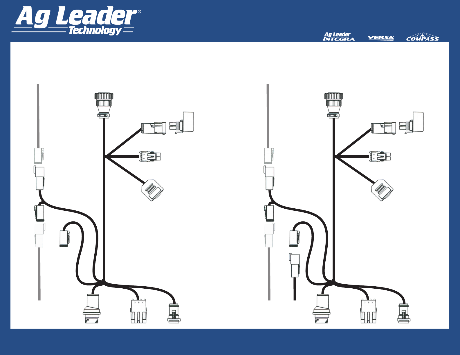
VT Quick Reference Guide
Cooper Bussman Relay Module
Pin#3=AWG8 (60A) from
Rear View of
2-pin Metri-Pak
High Current
Relay Module
60
amp
fuse
30
amp
fuse
Retrot Cable Kit (Generic Tractor) Wiring Diagram
Active
Termination
Cable PN
LED
2
4002587
LED
3
CAN A
Relay
3
4
1
ISO Plug
2
Pin#2=AWG10 (30A)
to Ground
to Ground
Pin#1=AWG8 (60A)
Weather
Pack Square
Shroud 4-pin
Power Control
ISOBUS CAN Extension PN 4002586-8,16
LED
1
CAN
POWER
MODULE
CAN B
Relay
Ground
Pin#4=AWG10(30A) +12
ECU Power from Circuit Board
Aux
Power
ISO T
ISO T
Aux Power of
ISOBUS display
cable in cab
CAN B of
ISOBUS display
cable in cab
Weather Pack
Square Shroud
4-pin power
Control of
ISOBUS display
cable in cab
LED
1
Solid blue LED indicates module
is receiving +12V from the
display energizing the High
Current Relay controlling High
Current across pins 1 and 3 of
ISO plug.
LED
2
Solid green LED indicates CAN
A is receiving +12V from the
display when CAN A relay is
closed.
LED
3
Solid green LED indicates CAN
B is receiving +12V from the
module circuit board across pins
2 and 4 of ISO Plug when CAN
B relay is closed.
ISOBUS Battery Cable
PN 4002865-8,16,22
Quick Reference Guide
AL: 2006300 - ENG Rev C
100 amp
Fuse
Battery
7
Page 8

VT Quick Reference Guide
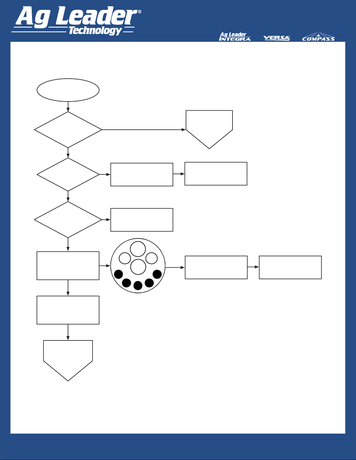
Troubleshooting Step 1: Virtual Terminal
Start
Latest display
rmware?
Yes
VT
button present
on lower left of
screen?
Yes
Press VT button located in
lower left screen.
Object
Pool(s) loaded
on screen?
Yes
No
No
No No
Upgrade rmware.
Enable Virtual Terminal
button from General tab of
Display Setup screen.
Status
Bar present
in the lower left of
display?
Yes
Has
Status Bar been
active for more than 15
minutes while object pool
loaded?
No
Wait while Object Pool(s)
nishes loading.
Go to Step 2:
Cables and
Power
Do
Object
Pool(s) look
right and function
correctly?
Yes
Troubleshooting Complete.
System should be in eld-ready
state.
Clear saved devices by
pressing Clear Saved
Device Interfaces button in
upper right corner of Virtual
No
Terminal Settings screen.
Leaving display POWERED
ON, cycle power to Tractor
ECU by turning key off to
tractor and turning back on.
Quick Reference Guide
Yes
look right and function
AL: 2006300 - ENG Rev C
Do
Object Pool(s)
correctly?
Yes
No
Go to Step 9:
ECU
8
Page 9
VT Quick Reference Guide
Troubleshooting Step 2: Cables and Power
Start
Go to Step 3:
OEM BUS
or Ag Leader ISOBUS
Retrot Cable?
OEM
Is
Ag
Leader display
cable T’d into OEM
cable?
Ag Leader ISOBUS Retrot Cable Kit
No
Connect display cable to
OEM BUS.
ISOBUS Retrot
Cable
Have Ag Leader dealer
consult ISOBUS System
Reference for support.
Yes
Is
the
implement
plugged into the ISO plug
on the rear of the
tractor?
Using voltmeter, check for
12VDC across pins 2 and 4;
and across pins 1 and 3 of
ISOBUS module plug.
Yes
Reconnect ISO Connector.
Go to Step 8:
Reload Implement
Object Pools
Plug implement into the ISO
No
plug on the rear of the tractor.
3/B
4/J
1/A
2/C
No
Check fuses and relays in
cab.
Contact your Tractor Dealer
for further diagnosis of tractor
circuitry.
Quick Reference Guide
AL: 2006300 - ENG Rev C
9
Page 10

VT Quick Reference Guide
Troubleshooting Step 3: ISOBUS Retrot Cable
Start
Is
4-pin
Power Control
Extension Cable plugged
into display cable and
fully seated?
Yes
Is
ISOBUS
CAN Extension
Cable T’d into Display
Cable and fully
seated?
Yes
Is
the
Active
Termination Cable
plugged into power on ISO
Display Cable and
fully seated?
Yes
Leaving the display power
ON, go to ISOBUS Retrot
Cable Module Mounting
Location.
Plug 4-pin Power Control
Extension Cable into the
No
display cable unit it clicks to
make sure it is fully seated.
No
Plug the ISOBUS CAN
Extension Cable into the
Display Cable until it clicks to
make sure it is fully seated.
Plug the Active Termination
No
Cable into power on the ISO
Display Cable until it clicks to
make sure it is fully seated.
Are
the 3
LEDs on the
CAN Power Module
Illuminated?
No
Yes
Is
the
implement
plugged into the ISO plug
on the rear of the
tractor?
No
Enable Virtual Terminal
button from General tab of
Yes
Go to Step 8:
Cycle Power to
ECU
Quick Reference Guide
AL: 2006300 - ENG Rev C
Step 4:
High Current
Relay Module
Setup screen.
10
Page 11

VT Quick Reference Guide
Troubleshooting Step 4: High Current Relay Module
Start
Is
battery
connected: (+)to
Pin A and (-) to ground of
High Current Relay
Module?
Connect (+Pos) battery
No
cable to Pin A and (-Neg)
battery cable to ground of
High Current Relay Module.
B
B
C
Yes
Are
battery cables
connected to battery?
Yes
Use a voltmeter and check
for 12V across Pin A and high
current relay module and
ground.
Yes
12V
across
Pin A and Ground
of Relay Module?
Yes
Check voltage across Pin B
and ground of Relay Module.
Yes
Are
12V present?
Yes
Check voltage across Pin C
and ground of Relay Module.
No
Connect battery cables to
battery.
No
No
Check 100 amp fuse on
battery cable.
Check 60 amp fuse of High
Current Relay Module.
2-pin Metri-Pak
High Current
Relay Module
60
amp
fuse
30
amp
fuse
A
Check That High Current
Relay on the High Current
Relay Module is energized.
Unplug the 2-pin Metri-Pak
from the relay. Unplugging
the connector removes
power and opens relay. Plug
connector back in and listen
for Relay to “Click” Closed.
If no “Click” is heard, the relay
has failed. Contact Ag Leader
Dealer for a replacement
High Current Relay Module.
Ground
Yes
Are
12V
present?
Yes
Check 30 Amp Fuse of High
No
Current Relay Module.
Quick Reference Guide
AL: 2006300 - ENG Rev C
Go to Step 5
CAN Power
Module
LED 1
11
Page 12

VT Quick Reference Guide
Troubleshooting Step 5: CAN Power Module LED 1
LED #1 (Blue) Indicates that the module is receiving high current power (+12 VDC) from the
display energizing the High Current Relay Controlling High Current across Pins 1 and 3 of the ISO
plug.
Start
Verify Display is Powered
On and
Tractor Key is On
Is
LED #1
Illuminated BLUE?
Yes
Go to Step 6
CAN Power
Module
LED 2
Disconnect 4 Pin Power
Control Extension Cable from
No
module.
Check voltages across
Pins A and D
Pins C and D
of Extension Cable.
Correct
Voltages?
12V across A and D
5V across C and
D
Yes
Contact Ag Leader Dealer for
Module Replacement.
4-pin Square
Weather
Pack with
Towers
Power
Control
CAN
POWER
MODULE
No
Disconnect 4 Pin Power
Control Extension Cable
From Display Cable In Cab.
Check voltages across
Pins A and D
Pins C and D
of Display Cable.
Correct
Voltages?
12V across A and D
5V across C and
Replace Power Control
Extension
Cable.
D
LED
1
Yes
LED
2
LED
3
CAN A
Relay
CAN B
Relay
Replace ISO Display Cable.
No
Quick Reference Guide
AL: 2006300 - ENG Rev C
12
Page 13

VT Quick Reference Guide
Troubleshooting Step 6: CAN Power Module LED 2
LED #2 (Green) Indicates CAN A is being provided high current power (+12V) from the CAN A
Relay of the CAN Power Module.
Start
LED#2
Illuminated
GREEN?
Yes
Leaving the Power Control
Extension Cable plugged into
the CAN Power Module, back
No
Probe Pins B (Pink Wire)
and D (Black Wire) of Power
Control Extension Pigtail on
CAN Power Module for 12V
by removing seals on the
backside of 4 Pin Weatherpack
and inserting voltmeter probes
into Pins B and D.
4-pin Square
Weather
Pack with
Towers
Power
Control
LED
1
CAN
POWER
MODULE
LED
2
LED
3
CAN A
Relay
CAN B
Relay
Go to Step 7:
CAN Power
Module
LED 3
Is voltage
correct?
No
CAN A Relay Failed
Contact Ag Leader
Dealer to Replace Module.
Yes
LED Failed.
Contact Ag Leader
Dealer to Replace Module.
Quick Reference Guide
AL: 2006300 - ENG Rev C
13
Page 14

VT Quick Reference Guide
Troubleshooting Step 7: CAN Power Module LED 3
LED #3 (Green) indicates ISOBUS/CAN B is being provided high current power (+12V) across
pins 2 and 4 of ISO Plug from CAN B relay.
4-pin Square
Start
LED#3
Illuminated
GREEN?
Weather
Pack with
Towers
Power
Control
CAN
POWER
MODULE
Using a Voltmeter Check for
No
12v Across Pins 2 and 4 of
ISO Connector
LED
1
LED
2
LED
CAN A
Relay
CAN B
Relay
4/J
3
3/B
1/A
2/C
2-pin Metri-Pak
High Current
Relay Module
60
amp
fuse
30
amp
fuse
Ground
Yes
Troubleshooting
complete. System should be
in eld-ready state.
Is voltage
correct?
Yes
Check for 12V across Pin C
of High Current Relay Module
and Ground.
Is
voltage correct?
Yes
LED Failed.
Contact Ag Leader Dealer to
replace module.
Quick Reference Guide
AL: 2006300 - ENG Rev C
No
No
CAN B Relay Failed.
Contact Ag Leader
Dealer to Replace Module.
Check 30 Amp Fuse of High
Current Relay Module.
14
Page 15

VT Quick Reference Guide
Troubleshooting Step 8:
Reload Implement Object Pools
Start
Leaving display POWERED
ON, Cycle Power to Tractor
ECU by turning OFF Key to
tractor and turning back On.
Object Pool(s)
on Screen?
Yes
Object
Pool(s) look
right
and function
correctly?
Yes
Troubleshooting
complete.
System should be in eld-
ready state.
No
lower left of display?
Been Active over 15
minutes while
Object Pool(s)
Go to Step 9:
No
Status
Bar in
Yes
Has
Status Bar
Load?
Yes
ECU
No
No
Wait while Object Pool(s)
nishes loading.
Quick Reference Guide
AL: 2006300 - ENG Rev C
15
Page 16

VT Quick Reference Guide
Troubleshooting Step 9: ECU Troubleshooting
ECU
Problem
Verify latest Firmware with
OEM, Update if
needed.
Did
Firmware
update x problem?
Yes
No
Is
Implement
UI
Ok and Malfunction
Limited to Implement High
Current Components
Not Functioning?
No
Call Ag Leader
Tech Support.
Check high current related
Yes
per steps 2-4 of
troubleshooting.
problem xed?
circuitry
Was
Yes
No
Troubleshooting
Complete. System should
be in eld-ready state.
Quick Reference Guide
AL: 2006300 - ENG Rev C
16
 Loading...