

Page 1

Agilent Technologies
Z5623A Option H48
Multiport Test Set
User’s and Service Guide
Manufacturing Part Number: Z5623-90016
Printed in USA
June 2005
© Copyright 2000-2002, 2005 Agilent Technologies, Inc. All rights reserved.
Page 2

Warranty Statement
THE MATERIAL CONTAINED IN THIS DOCUMENT IS PROVIDED “AS IS,” AND IS
SUBJECT TO BEING CHANGED, WITHOUT NOTICE, IN FUTURE EDITIONS. FURTHER,
TO THE MAXIMUM EXTENT PERMITTED BY APPLICABLE LAW, AGILENT DISCLAIMS
ALL WARRANTIES, EITHER EXPRESS OR IMPLIED WITH REGARD TO THIS MANUAL
AND ANY INFORMATION CONTAINED HEREIN, INCLUDING BUT NOT LIMITED TO THE
IMPLIED WARRANTIES OF MERCHANTABILITY AND FITNESS FOR A PARTICULAR
PURPOSE. AGILENT SHALL NOT BE LIABLE FOR ERRORS OR FOR INCIDENTAL
OR CONSEQUENTIAL DAMAGES IN CONNECTION WITH THE FURNISHING, USE, OR
PERFORMANCE OF THIS DOCUMENT OR ANY INFORMATION CONTAINED HEREIN.
SHOULD AGILENT AND THE USER HAVE A SEPARATE WRITTEN AGREEMENT WITH
WARRANTY TERMS COVERING THE MATERIAL IN THIS DOCUMENT THAT CONFLICT
WITH THESE TERMS, THE WARRANTY TERMS IN THE SEPARATE AGREEMENT WILL
CONTROL.
DFARS/Restricted Rights Notice
If software is for use in the performance of a U.S. Government prime contract or
subcontract, Software is delivered and licensed as “Commercial computer software” as
defined in DFAR 252.227-7014 (June 1995), or as a “commercial item” as defined in
FAR 2.101(a) or as “Restricted computer software” as defined in FAR 52.227-19 (June
1987) or any equivalent agency regulation or contract clause. Use, duplication or
disclosure of Software is subject to Agilent Technologies’ standard commercial license
terms, and non-DOD Departments and Agencies of the U.S. Government will receive no
greater than Restricted Rights as defined in FAR 52.227-19(c)(1-2) (June 1987). U.S.
Government users will receive no greater than Limited Rights as defined in FAR
52.227-14 (June 1987) or DFAR 252.227-7015 (b)(2) (November 1995), as applicable in
any technical data.
ii
Page 3

Safety Notes
The following safety notes are used throughout this document. Familiarize yourself
with each of these notes and its meaning before performing any of the procedures in
this document.
WARNING Warning denotes a hazard. It calls attention to a procedure
which, if not correctly performed or adhered to, could result in
injury or loss of life. Do not proceed beyond a warning note
until the indicated conditions are fully understood and met.
CAUTION Caution denotes a hazard. It calls attention to a procedure that, if not
correctly performed or adhered to, could result in damage to or
destruction of the instrument. Do not proceed beyond a caution sign
until the indicated conditions are fully understood and met.
Statement of Compliance
This instrument has been designed and tested in accordance with IEC Publication 1010, Safety
Requirements for Electronic Measuring Apparatus, and has been supplied in a safe condition. The
instruction documentation contains information and warnings which must be followed by the user to
ensure safe operation and to maintain the instrument in a safe condition.
Definitions
• Specifications describe the performance of parameters covered by the product warranty
(temperature –0 to 55 °C, unless otherwise noted.)
• Typical describes additional product performance information that is not covered by the
product warranty. It is performance beyond specification that 80% of the units exhibit
with a 95% confidence level over the temperature range 20 to 30 °C. Typical
performance does not include measurement uncertainty.
• Nominal values indicate expected performance or describe product performance that is
useful in the application of the product, but is not covered by the product warranty.
iii
Page 4

iv
Page 5

Contents
1. Instrument Description
Overview . . . . . . . . . . . . . . . . . . . . . . . . . . . . . . . . . . . . . . . . . . . . . . . . . . . . . . 1-2
Specifications . . . . . . . . . . . . . . . . . . . . . . . . . . . . . . . . . . . . . . . . . . . . . . . . . . . 1-3
Guaranteed Performance. . . . . . . . . . . . . . . . . . . . . . . . . . . . . . . . . . . . . . . . . 1-4
Typical Performance. . . . . . . . . . . . . . . . . . . . . . . . . . . . . . . . . . . . . . . . . . . . 1-5
Electrical Requirements . . . . . . . . . . . . . . . . . . . . . . . . . . . . . . . . . . . . . . . . . . . 1-6
Environmental Requirements. . . . . . . . . . . . . . . . . . . . . . . . . . . . . . . . . . . . . . . 1-6
Operating Environment. . . . . . . . . . . . . . . . . . . . . . . . . . . . . . . . . . . . . . . . . . 1-6
Non-Operating Storage Conditions . . . . . . . . . . . . . . . . . . . . . . . . . . . . . . . . 1-6
General Characteristics. . . . . . . . . . . . . . . . . . . . . . . . . . . . . . . . . . . . . . . . . . . . 1-7
Weight. . . . . . . . . . . . . . . . . . . . . . . . . . . . . . . . . . . . . . . . . . . . . . . . . . . . . . . 1-7
Cabinet Dimensions . . . . . . . . . . . . . . . . . . . . . . . . . . . . . . . . . . . . . . . . . . . . 1-7
Miscellaneous Characteristics. . . . . . . . . . . . . . . . . . . . . . . . . . . . . . . . . . . . . 1-7
Available Options. . . . . . . . . . . . . . . . . . . . . . . . . . . . . . . . . . . . . . . . . . . . . . . . 1-7
UK6. . . . . . . . . . . . . . . . . . . . . . . . . . . . . . . . . . . . . . . . . . . . . . . . . . . . . . . . . 1-7
Rack Ear Mounts . . . . . . . . . . . . . . . . . . . . . . . . . . . . . . . . . . . . . . . . . . . . . . 1-7
Cleaning and Shipping Instructions . . . . . . . . . . . . . . . . . . . . . . . . . . . . . . . . . . 1-8
2. Installation
Checking the Shipment. . . . . . . . . . . . . . . . . . . . . . . . . . . . . . . . . . . . . . . . . . . . 2-2
Recommended Additional Equipment . . . . . . . . . . . . . . . . . . . . . . . . . . . . . . . . 2-3
Familiarization with Safety Requirements. . . . . . . . . . . . . . . . . . . . . . . . . . . . . 2-4
Electrical Preparations . . . . . . . . . . . . . . . . . . . . . . . . . . . . . . . . . . . . . . . . . . . . 2-4
Environmental Preparations . . . . . . . . . . . . . . . . . . . . . . . . . . . . . . . . . . . . . . . . 2-7
Test Set Familiarization . . . . . . . . . . . . . . . . . . . . . . . . . . . . . . . . . . . . . . . . . . . 2-9
Front Panel . . . . . . . . . . . . . . . . . . . . . . . . . . . . . . . . . . . . . . . . . . . . . . . . . . . 2-9
Rear Panel. . . . . . . . . . . . . . . . . . . . . . . . . . . . . . . . . . . . . . . . . . . . . . . . . . . 2-11
Setting the GPIB Address of the Test Set . . . . . . . . . . . . . . . . . . . . . . . . . . . . 2-13
Connecting and Turning on the Test Set . . . . . . . . . . . . . . . . . . . . . . . . . . . . . 2-14
3. Using the Network Analyzer to Control the Test Set
Preparing the Analyzer to Control the Test Set . . . . . . . . . . . . . . . . . . . . . . . . . 3-2
How to Send a Manual Command . . . . . . . . . . . . . . . . . . . . . . . . . . . . . . . . . . . 3-7
Common Errors in Manual Commands . . . . . . . . . . . . . . . . . . . . . . . . . . . . . . . 3-8
A List of GPIB Commands . . . . . . . . . . . . . . . . . . . . . . . . . . . . . . . . . . . . . . . . 3-9
Restoring the Analyzer to its Normal Configuration . . . . . . . . . . . . . . . . . . . . 3-12
Disaster Recovery. . . . . . . . . . . . . . . . . . . . . . . . . . . . . . . . . . . . . . . . . . . . . . . 3-13
Contents-1
Page 6

Malfunctioning Command Window. . . . . . . . . . . . . . . . . . . . . . . . . . . . . . . 3-13
Malfunctioning Network Analyzer. . . . . . . . . . . . . . . . . . . . . . . . . . . . . . . . 3-18
4. Calibrating the Network Analyzer
Performing the Calibration. . . . . . . . . . . . . . . . . . . . . . . . . . . . . . . . . . . . . . . . . 4-2
Renaming the Calibration File . . . . . . . . . . . . . . . . . . . . . . . . . . . . . . . . . . . . . . 4-7
Recalling and Examining Calibrations. . . . . . . . . . . . . . . . . . . . . . . . . . . . . . . 4-14
How to Recall a Calibration . . . . . . . . . . . . . . . . . . . . . . . . . . . . . . . . . . . . . 4-14
Method 1. Calibration File Is Not On “Quick Recall” List. . . . . . . . . . . . 4-14
Method 2. Calibration File Is On “Quick Recall” List . . . . . . . . . . . . . . . 4-16
How to Turn a Calibration On and Off. . . . . . . . . . . . . . . . . . . . . . . . . . . . . 4-16
How to Examine the Properties of a Calibration . . . . . . . . . . . . . . . . . . . . . 4-18
5. Performance Verification
Setting Test Limits . . . . . . . . . . . . . . . . . . . . . . . . . . . . . . . . . . . . . . . . . . . . . . . 5-2
Test Strategy. . . . . . . . . . . . . . . . . . . . . . . . . . . . . . . . . . . . . . . . . . . . . . . . . . . . 5-4
Insertion Loss . . . . . . . . . . . . . . . . . . . . . . . . . . . . . . . . . . . . . . . . . . . . . . . . . 5-5
Return Loss. . . . . . . . . . . . . . . . . . . . . . . . . . . . . . . . . . . . . . . . . . . . . . . . . . . 5-5
Crosstalk . . . . . . . . . . . . . . . . . . . . . . . . . . . . . . . . . . . . . . . . . . . . . . . . . . . . . 5-6
Setting Up Limit Testing . . . . . . . . . . . . . . . . . . . . . . . . . . . . . . . . . . . . . . . . . . 5-7
Limit Testing for Insertion Loss . . . . . . . . . . . . . . . . . . . . . . . . . . . . . . . . . . . 5-8
Recalling the Calibration. . . . . . . . . . . . . . . . . . . . . . . . . . . . . . . . . . . . . . . 5-8
Specifying Measurement Type, Title, and Scaling . . . . . . . . . . . . . . . . . . . 5-8
Setting Up the Limit Table . . . . . . . . . . . . . . . . . . . . . . . . . . . . . . . . . . . . 5-12
Turning On Limit Lines and Limit Testing. . . . . . . . . . . . . . . . . . . . . . . . 5-14
Saving the Limit Test File. . . . . . . . . . . . . . . . . . . . . . . . . . . . . . . . . . . . . 5-15
Checking the Limit Test File. . . . . . . . . . . . . . . . . . . . . . . . . . . . . . . . . . . 5-17
Limit Testing for Return Loss (Port Active) . . . . . . . . . . . . . . . . . . . . . . . . 5-19
Recalling the Calibration. . . . . . . . . . . . . . . . . . . . . . . . . . . . . . . . . . . . . . 5-19
Specifying Measurement Type, Title, and Scaling . . . . . . . . . . . . . . . . . . 5-19
Setting Up the Limit Table . . . . . . . . . . . . . . . . . . . . . . . . . . . . . . . . . . . . 5-20
Turning On Limit Lines and Limit Testing. . . . . . . . . . . . . . . . . . . . . . . . 5-21
Saving the Limit Test File. . . . . . . . . . . . . . . . . . . . . . . . . . . . . . . . . . . . . 5-22
Checking the Limit Test File. . . . . . . . . . . . . . . . . . . . . . . . . . . . . . . . . . . 5-22
Limit Testing for Return Loss (Port Off) . . . . . . . . . . . . . . . . . . . . . . . . . . . 5-24
Recalling the “Port Active” Limit Test File . . . . . . . . . . . . . . . . . . . . . . . 5-24
Specifying the Title. . . . . . . . . . . . . . . . . . . . . . . . . . . . . . . . . . . . . . . . . . 5-24
Setting Up the Limit Table . . . . . . . . . . . . . . . . . . . . . . . . . . . . . . . . . . . . 5-24
Saving the Limit Test File. . . . . . . . . . . . . . . . . . . . . . . . . . . . . . . . . . . . . 5-25
Recalling the Limit Test File. . . . . . . . . . . . . . . . . . . . . . . . . . . . . . . . . . . 5-25
Contents-2
Page 7

Contents
Limit Testing for Crosstalk . . . . . . . . . . . . . . . . . . . . . . . . . . . . . . . . . . . . . 5-26
Specifying Output Power . . . . . . . . . . . . . . . . . . . . . . . . . . . . . . . . . . . . . 5-26
Specifying IF Bandwidth and Averaging . . . . . . . . . . . . . . . . . . . . . . . . . 5-28
Specifying Measurement Type, Title, and Scaling . . . . . . . . . . . . . . . . . . 5-32
Setting Up the Limit Table . . . . . . . . . . . . . . . . . . . . . . . . . . . . . . . . . . . . 5-34
Turning On Limit Lines and Limit Testing. . . . . . . . . . . . . . . . . . . . . . . . 5-35
Saving the Limit Test File. . . . . . . . . . . . . . . . . . . . . . . . . . . . . . . . . . . . . 5-35
Recalling the Limit Test File. . . . . . . . . . . . . . . . . . . . . . . . . . . . . . . . . . . 5-35
Verifying Return Loss and Insertion Loss Specifications . . . . . . . . . . . . . . . . 5-36
Measurements Using The Reflection Port . . . . . . . . . . . . . . . . . . . . . . . . . . 5-36
Measurements Using The Transmission Port . . . . . . . . . . . . . . . . . . . . . . . . 5-37
Verifying Crosstalk Specs . . . . . . . . . . . . . . . . . . . . . . . . . . . . . . . . . . . . . . . . 5-39
6. Measuring Multiport Devices
Calibrating the Test System . . . . . . . . . . . . . . . . . . . . . . . . . . . . . . . . . . . . . . . . 6-2
7. Advanced Topics
Using an External Computer to Control the Test Set. . . . . . . . . . . . . . . . . . . . . 7-2
GPIB Queries . . . . . . . . . . . . . . . . . . . . . . . . . . . . . . . . . . . . . . . . . . . . . . . . . 7-2
Box Identification . . . . . . . . . . . . . . . . . . . . . . . . . . . . . . . . . . . . . . . . . . . . 7-3
Switch Count . . . . . . . . . . . . . . . . . . . . . . . . . . . . . . . . . . . . . . . . . . . . . . . 7-3
Languages . . . . . . . . . . . . . . . . . . . . . . . . . . . . . . . . . . . . . . . . . . . . . . . . . . . . 7-3
Using Rocky Mountain Basic (RMB). . . . . . . . . . . . . . . . . . . . . . . . . . . . . 7-3
Using Quick Basic or Visual Basic. . . . . . . . . . . . . . . . . . . . . . . . . . . . . . . 7-3
Using HPVEE . . . . . . . . . . . . . . . . . . . . . . . . . . . . . . . . . . . . . . . . . . . . . . . 7-4
Using National Instruments VISA . . . . . . . . . . . . . . . . . . . . . . . . . . . . . . . 7-5
Using the Control Lines Connector . . . . . . . . . . . . . . . . . . . . . . . . . . . . . . . . . . 7-6
Control Line Commands for 9-Pin Connector:. . . . . . . . . . . . . . . . . . . . . . . . 7-6
Suggested External Circuitry . . . . . . . . . . . . . . . . . . . . . . . . . . . . . . . . . . . . . 7-7
8. Service
Adjustments . . . . . . . . . . . . . . . . . . . . . . . . . . . . . . . . . . . . . . . . . . . . . . . . . . . . 8-2
Theory of Operation . . . . . . . . . . . . . . . . . . . . . . . . . . . . . . . . . . . . . . . . . . . . . . 8-3
System Theory . . . . . . . . . . . . . . . . . . . . . . . . . . . . . . . . . . . . . . . . . . . . . . . . 8-3
A1 Power Supply Theory . . . . . . . . . . . . . . . . . . . . . . . . . . . . . . . . . . . . . . . . 8-3
A2 Controller and A3 Switch Driver Board Theory. . . . . . . . . . . . . . . . . . . . 8-4
A4 Front Panel Display Theory . . . . . . . . . . . . . . . . . . . . . . . . . . . . . . . . . . . 8-4
Contents-3
Page 8

Connector Replacement . . . . . . . . . . . . . . . . . . . . . . . . . . . . . . . . . . . . . . . . . 8-4
Troubleshooting . . . . . . . . . . . . . . . . . . . . . . . . . . . . . . . . . . . . . . . . . . . . . . . . . 8-5
General Troubleshooting Notes . . . . . . . . . . . . . . . . . . . . . . . . . . . . . . . . . . . 8-5
Troubleshooting Power Supply Problems . . . . . . . . . . . . . . . . . . . . . . . . . . . 8-5
Troubleshooting the Front Panel Board . . . . . . . . . . . . . . . . . . . . . . . . . . . . . 8-6
Troubleshooting the Controller and Switch Driver Boards . . . . . . . . . . . . . . 8-6
List of Replaceable Parts . . . . . . . . . . . . . . . . . . . . . . . . . . . . . . . . . . . . . . . . . . 8-7
9. Safety and Regulatory Information
Safety Information . . . . . . . . . . . . . . . . . . . . . . . . . . . . . . . . . . . . . . . . . . . . . . . 9-2
Warnings. . . . . . . . . . . . . . . . . . . . . . . . . . . . . . . . . . . . . . . . . . . . . . . . . . . . . 9-2
Cautions . . . . . . . . . . . . . . . . . . . . . . . . . . . . . . . . . . . . . . . . . . . . . . . . . . . . . 9-3
Instrument Markings. . . . . . . . . . . . . . . . . . . . . . . . . . . . . . . . . . . . . . . . . . . . 9-4
Regulatory Information . . . . . . . . . . . . . . . . . . . . . . . . . . . . . . . . . . . . . . . . . . . 9-5
Statement of Compliance with IEC 1010 . . . . . . . . . . . . . . . . . . . . . . . . . . . . 9-5
Declaration of Compliance with German Noise Requirements . . . . . . . . . . . 9-5
10. Contacting Agilent
Contacting Agilent . . . . . . . . . . . . . . . . . . . . . . . . . . . . . . . . . . . . . . . . . . . . . . 10-2
Contents-4
Page 9

1 Instrument Description
This chapter contains the following sections:
• Overview
• Specifications
• Electrical Requirements
• Environmental Requirements
• General Characteristics
• Available Options
• Cleaning and Shipping Instructions
Agilent Technologies Z5623A Option H48 1-1
Page 10
Instrument Description
Overview
Overview
The Agilent Z5623A Option H48 Multiport Test Set is designed for use
with 50 Ω Network Analyzers such as the Agilent PNA Series (Models
E8356A, E8357A, and E8358A). Figure 1-1 shows a typical equipment
setup.
The test set reduces the time required to test multiport devices having
up to eight ports (distribution amplifiers, taps, switches, couplers, etc.).
It does this by reducing the number of device reconnects the operator
must perform. The test set can connect each of its test ports to any of
the following:
• Reflection Port
• Transmission Port
• 50 Ω termination internal to the test set.
Switching is performed with mechanical switches.
The test set is controlled by means of its GPIB interface. The control
can be performed either by a PNA Series network analyzer or by an
external computer.
NOTE
This User's and Service Guide documents the use of the test set with an
Agilent E8358A network analyzer.
Figure 1-1 Typical Equipment Setup
Network Analyzer
Port 1
RF Cables
Reflection
Port
1
Z5623A Option H48
Test Ports
2
3
4
56
Port 2
Transmission
8
7
Port
1-2 Agilent Technologies Z5623A Option H48
Page 11

Instrument Description
Specifications
Specifications
Agilent provides two different types of specifications for the test set:
• Guaranteed performance specs
• Typical performance specs
Typical performance specs have been benchmarked during product
development, but are not tested by the factory and are not guaranteed.
Agilent Technologies Z5623A Option H48 1-3
Page 12

Instrument Description
Specifications
Guaranteed Performance
Table 1-1 Agilent Z5623A Option H48 Guaranteed Performance Specs
Parameter Specification
Frequency Range 300 kHz to 9.0 GHz
Crosstalk
a
Return Loss (port active)
Return Loss (port off)
Insertion Loss
h
g
1) –110 dB
2) –105 dB
3) –95 dB
4) –90 dB
f
1) 24 dB
2) 18 dB
3) 14 dB
4) 9 dB
1) 26 dB
2) 20 dB
3) 16 dB
4) 14 dB
1) 1.5 dB
2) 2.0 dB
3) 2.5 dB
4) 3.5 dB
b
c
d
e
b
c
d
e
b
c
d
e
b
c
d
e
Switch Lifetime 5 million cycles
Maximum Input Power
1 Watt (RF + DC)
i
a.Between any two non-connected signal paths
b. Band 1 (300 kHz to 1.3 GHz)
c. Band 2 (1.3 GHz to 3.0 GHz)
d. Band 3 (3.0 GHz to 6.0 GHz)
e. Band 4 (6.0 GHz to 9.0 GHz)
f.When using an external termination on the Reflection or
Transmission port
g.When using one of the 50 Ω internal terminations
h.From any test set port to the Reflection or Transmission port
i. Set by the power handling capability of the 50 Ω internal
terminations
1-4 Agilent Technologies Z5623A Option H48
Page 13

Typical Performance
Table 1-2 Agilent Z5623A Option H48 Typical Performance Specs
Parameter Typical Performance
Instrument Description
Specifications
Source Power (max)
a
1) –8.0 dBm
2) –8.0 dBm
3) –7.0 dBm
4) –1.0 dBm
Dynamic Range (max)f1) 110 dB
2) 105 dB
3) 95 dB
4) 90 dB
Cycle Time (minimum;
IF BW = 35 kHz)
g
1) 430 mS (Dynamic Range = 86 dB)
2) 430 mS (Dynamic Range = 89 dB)
b
c
d
e
b
c
d
e
3) 430 mS (Dynamic Range = 78 dB)
4) 430 mS (Dynamic Range = 71 dB)
Cycle Time (@ 100 dB
Dynamic Range; IF
BW = 3 kHz)
g
2) 900 mS
3) 900 mS
c
d
Switching Time 11 mS
a. Power measured at test ports 1-8 on Z5623A Option
H48 when connected to the E8358A using the
8120-4782 RF Jumper cables supplied.
b. Band 1 (300 kHz to 1.3 GHz)
c. Band 2 (1.3 GHz to 3.0 GHz)
d. Band 3 (3.0 GHz to 6.0 GHz)
e. Band 4 (6.0 GHz to 9.0 GHz)
f. IF Bandwidth set to 10 Hz
g. Conditions: 2 Windows, 4 Channels, 8 Traces,
2-port cal, no band crossings, 201points.
b
c
d
e
Agilent Technologies Z5623A Option H48 1-5
Page 14

Instrument Description
Electrical Requirements
Electrical Requirements
The alternating-current (AC) power that is supplied to the test set must
meet the following requirements:
Voltage: 90 to 250 Vac
Frequency: 48 to 66 Hz
Available power: 40 watts minimum
If the available AC line voltage is outside the 90 to 250 Vac range, an
autotransformer that provides third wire continuity to earth ground
may be used.
Environmental Requirements
CAUTION
Operating Environment
Indoor use only
Operating temperature: 0 to 55 °C
Maximum relative humidity: 80 percent for temperatures up to 31 °C
decreasing linearly to 50 percent relative humidity at 40 °C
Altitude: up to 15,000 feet (4,572 meters)
Enclosure protection: IP 20, according to IEC 529
This product is designed for use in INSTALLATION CATEGORY II,
and POLLUTION DEGREE 2, per IEC 101 and 664 respectively.
Non-Operating Storage Conditions
Temperature: –40 °C to +70 °C
Humidity: 0 to 90 percent relative at +65 °C (non-condensing)
Altitude: 0 to 15,240 meters (50,000 feet)
1-6 Agilent Technologies Z5623A Option H48
Page 15

Instrument Description
General Characteristics
General Characteristics
Weight
Net: Approximately 9 kg
Shipping: Approximately 20 kg
Cabinet Dimensions
These dimensions exclude front and rear panel protrusions.
89 mm H by 425 mm W by 500 mm D (3.5 in by 16.75 in by 19.7 in)
Miscellaneous Characteristics
RF connectors: Type N female
Switch type: Mechanical
I/O Control: GPIB
Available Options
UK6
Option UK6 provides a commercial calibration certificate including
actual test data. Data includes test results including reflection,
transmission, and crosstalk for all test ports.
Rack Ear Mounts
Option 908, part number 5062-3974, provides rack mounts that make it
quick and easy to install or remove the test set from a mainframe.
For further information on these options, please contact Agilent
Technologies. Refer to Chapter 10 , “Contacting Agilent.”
Agilent Technologies Z5623A Option H48 1-7
Page 16

Instrument Description
Cleaning and Shipping Instructions
Cleaning and Shipping Instructions
Cleaning
Clean the instrument cabinet using a damp cloth only.
Shipping
Always transport or ship the instrument using the original packaging if
possible. If not, comparable packaging must be used.
1-8 Agilent Technologies Z5623A Option H48
Page 17

2 Installation
This chapter contains the following sections:
• Checking the Shipment
• Recommended Additional Equipment
• Familiarization with Safety Requirements
• Electrical Preparations
• Environmental Preparations
• Test Set Familiarization
• Setting the GPIB Address of the Test Set
• Connecting and Turning on the Test Set
Agilent Technologies Z5623A Option H48 2 -1
Page 18

Installation
Checking the Shipment
Checking the Shipment
After the test set has been unpacked, keep the original packaging
materials so they can be used if you need to transport the instrument.
Check the items received against Table 2-1 to make sure you have
received everything.
Inspect the test set and all accessories for any signs of damage that may
have occurred during shipment. If your test set or any accessories
appear to be damaged or missing, call Agilent Technologies. Refer to
Chapter 10 , “Contacting Agilent.”
Table 2-1 Accessories Supplied with Z5623A Option H48
Description Agilent Part Number Quantity
Power Cord See Figure 2-2 on page 2-6 1
Front Handle Kit 5063-9226 1
Rack Mount Kit 5063-9232 1
RF Cable 8120-4782 2
GPIB Cable .5M HP 10833D 1
User’s and Service Guide Z5623-90016 1
2 -2 Agilent Technologies Z5623A Option H48
Page 19

Recommended Additional Equipment
Recommended Additional Equipment
The equipment listed in Table 2-2 is not shipped with the test set, but is
recommended for use with it. The remainder of this User’s and Service
Guide assumes that the user has the listed equipment (or its
equivalent) available.
Table 2-2 Recommended Equipment Not Supplied With Test Set
Description Model Or Part Number Quantity
Installation
PNA Series Network
Analyzer
Electronic Calibration
Module
Keyboard with USB
cable
Mouse with USB cable Hewlett-Packard Model No.
USB Quad Hub Peracom Model No.
USB Cable
RF Cable (24”)
9/16” Wrench Agilent Part No. 8710-1770 1
3/4” Torque Wrench Agilent Part No. 8710-1766 1
Type N 50 Ohm Male
Short
Type N 50 Ohm Female
Short
Agilent Model No.
E8356A, E8357A, or E8358A
Agilent Part No. 85072-60007 1
Hewlett-Packard Model No.
SK-2502U
M-UB48
UH4000A
Peracom Model No. CA2000A
Agilent Part No. 8120-4781
Agilent Part No. 85032-60016 2
Agilent Part No. 85032-60015 2
a
a
a,b
a,b
a
1
1
1
1
3
Type N 50 Ohm Female
Termination
Type N 50 Ohm
Female-Female Adapter
Agilent Part No. 85032-60018 2
Agilent Part No. 85032-60021 1
a. Or equivalent
b. Available from Peracom Networks, Inc., Cary, North Carolina
(www.peracom.com).
Agilent Technologies Z5623A Option H48 2 -3
Page 20

Installation
Familiarization with Safety Requirements
Familiarization with Safety Requirements
This document contains two types of safety notices: Warnings and
Cautions.
A Warning denotes a hazard that may endanger the operator.
A Caution denotes a hazard that may endanger the instrument.
Before proceeding to the Electrical Preparations described in the next
section, turn to Chapter 9, “Safety and Regulatory Information,” and
review the Warnings, Cautions, and safety markings that apply to this
instrument.
Electrical Preparations
1. Ensure that the “Electrical Requirements” on page 1-6 are met.
2. Verify that the power cable is not damaged and that the power
source outlet provides a protective earth ground contact. Note that
Figure 2-1 on page 2-5 depicts only one type of power source outlet.
Refer to Figure 2-2 on page 2-6 to see the different types of power
cord plugs that can be used with your test set.
Cables are available in different lengths. For descriptions and part
numbers of cables other than those described in Figure 2-2, call
Agilent Technologies. Refer to Chapter 10 , “Contacting Agilent.”
3. If this product is to be powered by autotransformer, make sure the
common terminal is connected to the neutral (grounded) side of the
ac power supply.
2 -4 Agilent Technologies Z5623A Option H48
Page 21
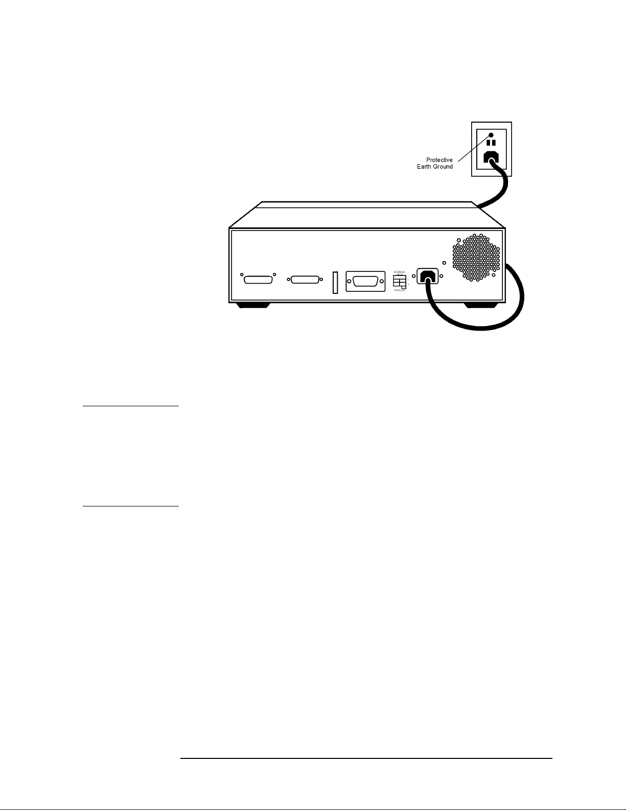
Figure 2-1 Protective Earth Ground
Installation
Electrical Preparations
WARNING
This is a Safety Class I product (provided with a protective
earthing ground incorporated in the power cord). The mains
plug shall only be inserted into a socket outlet provided with a
protective earth contact. Any interruption of the protective
conductor, inside or outside the instrument, is likely to make
the instrument dangerous. Intentional interruption of the
protective conductor is prohibited.
Agilent Technologies Z5623A Option H48 2 -5
Page 22
Installation
Electrical Preparations
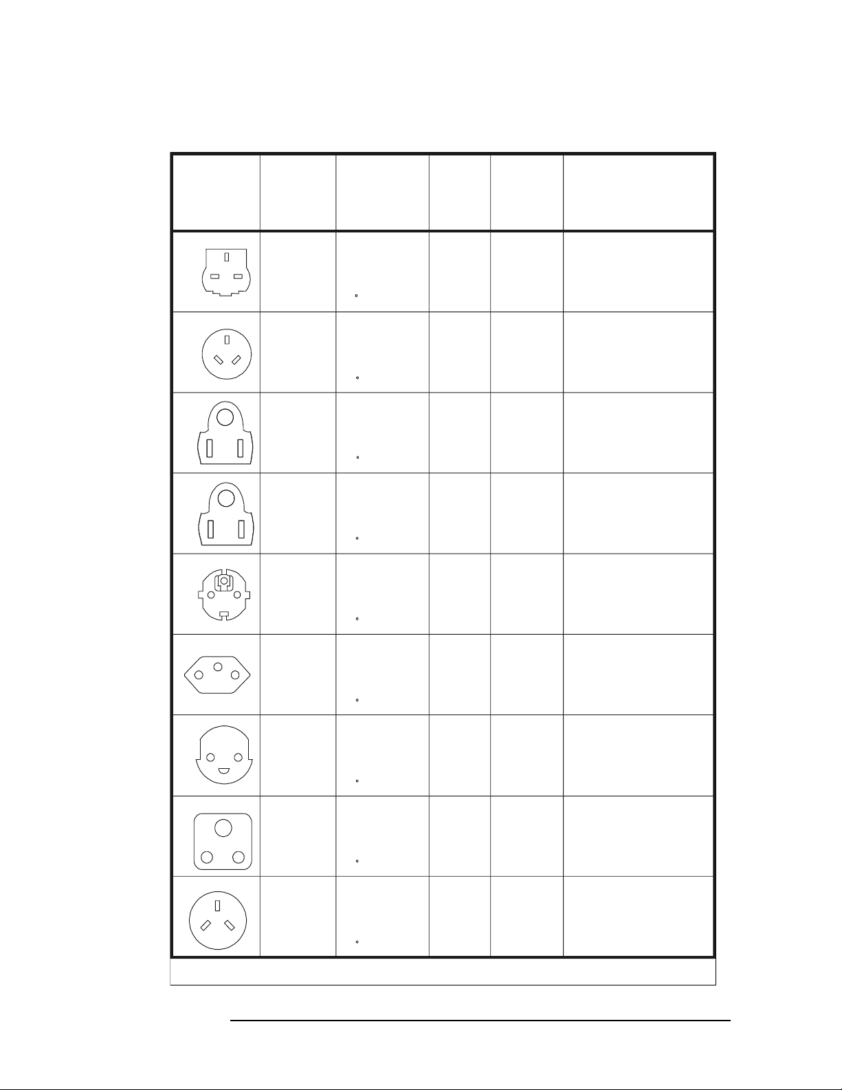
Figure 2-2 Power Cables
Plug Type
250V
250V
125V
125V
250V
230V
220V
E
LN
E
LN
EE
NNLLEENNLL
EE
NNLLEENNLL
E
E
L
N
NL
E
LN
a
Number
8120-8705
8120-8709
8120-1369
8120-0696
8120-1378
8120-1521
8120-4753
8120-4754
8120-1689
8120-1692
8120-2104
8120-2296
8120-2956
Cable
Part
b
Plug
Description
Straight
BS 1363A
90
Straight
AS 3112
90
Straight
NEMA 5-15P
90
Straight
NEMA 5-15P
90
Straight
CEE 7/VII
90
Straight
SEV Type 12
90
Straight
SR 107-2-D
Length
cm (in.)
229 (90)
229 (90)
210 (79)
200 (78)
203 (80)
203 (80)
229 (90)
229 (90)
200 (78)
200 (78)
200 (78)
200 (78)
200 (78)
Cable
Color
Mint Gray
Mint Gray
Gray
Gray
Jade Gray
Jade Gray
Gray
Gray
Mint Gra y
Mint Gray
Gray
Gray
Gray
For Use
in Country
Option 900
United Kingdom, Hong
Kong, Cyprus, Nigeria,
Singapore, Zimbabwe
Option 901
Argentina, Australia,
New Zealand, Mainland
China
Option 903
United States, Canada,
Brazil, Colombia,
Mexico,Philippines,
Saudi Arabia, Taiwan
Option 918
Japan
Option 902
Continental Europe,
Central African Republic,
United Arab Republic
Option 906
Switzerland
Option 912
Denmark
8120-2957
250V
E
L
8120-4211
N
8120-4600
250V
E
N
8120-5182
L
8120-5181
a. E =earth ground, L = line, and N = neutral.
b. Plug identifier numbers describe the plug only. The Agilent Technologies part number is for the complete cable assembly.
90
Straight
IEC 83-B1
90
Straight
SI 32
90
200 (78)
200 (78)
200 (78)
200 (78)
200 (78)
Gray
Mint Gray
Mint Gray
Jade Gray
Jade Gray
Option 917
South Africa, India
Option 919
Israel
2 -6 Agilent Technologies Z5623A Option H48
Page 23

Environmental Preparations
1. Ensure that the “Environmental Requirements” on page 1-6 are met.
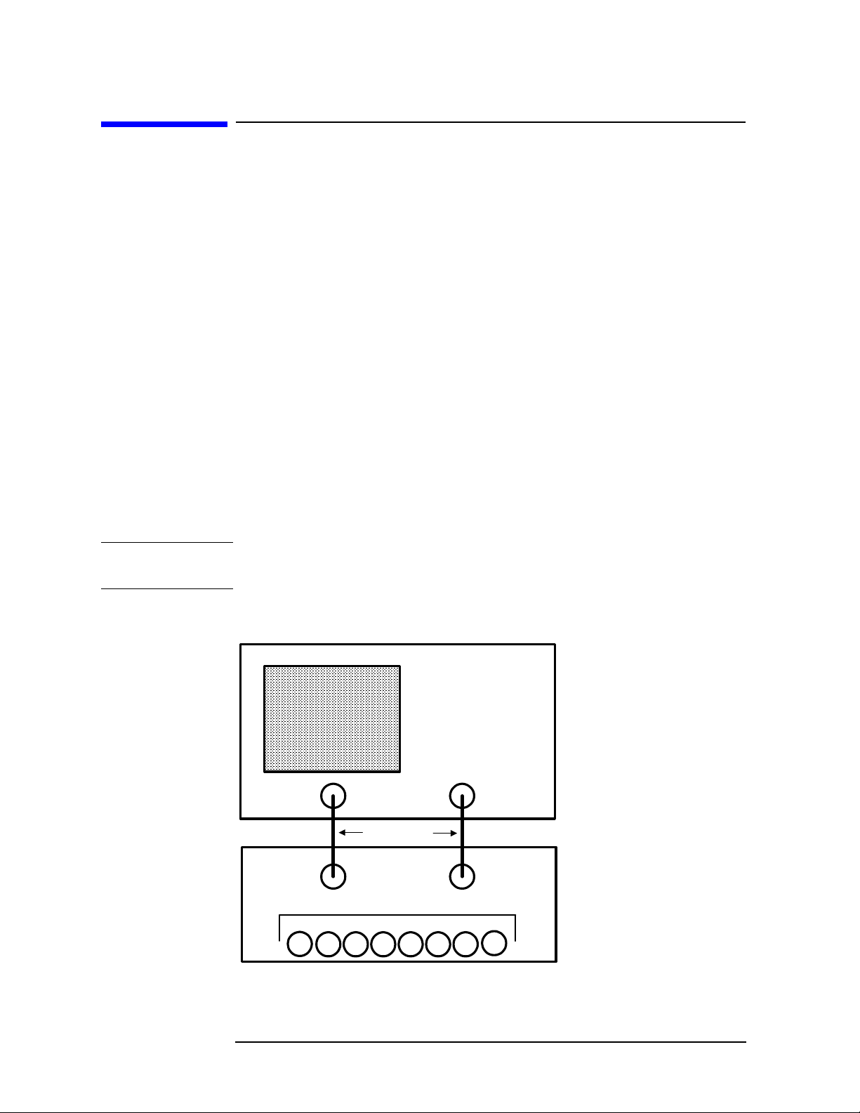
2. If you are installing the test set into a cabinet, ensure there are at
least two inches of clearance around the sides and back of the test
set and the system cabinet. See Figure 2-3. The convection into and
out of the test set must not be restricted. The ambient temperature
(outside the cabinet) must be less than the maximum operating
temperature of the test set by 4 °C for every 100 watts dissipated in
the cabinet.
Figure 2-3 Ventilation Clearance Requirements
Installation
Environmental Preparations
CAUTION
If the total power dissipated in the cabinet is greater than 800 watts,
forced convection must be used.
Agilent Technologies Z5623A Option H48 2 -7
Page 24
Installation
Environmental Preparations
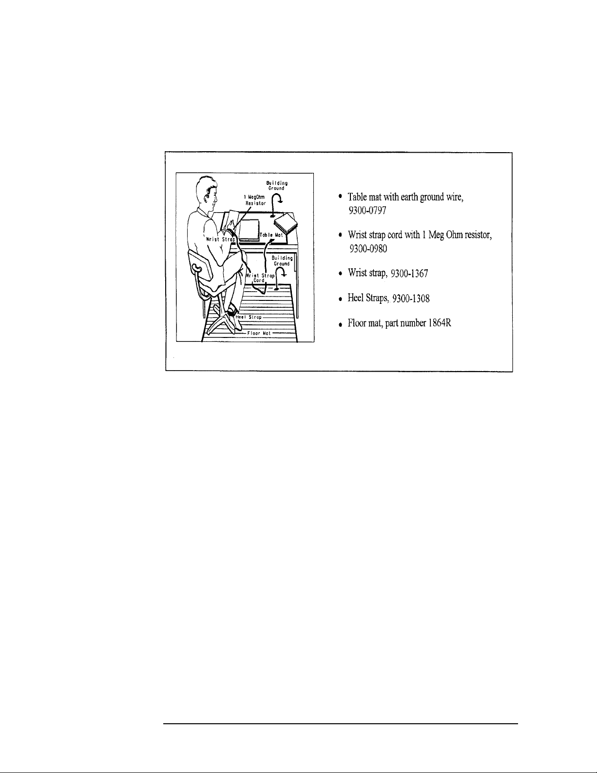
3. Set up a static safe workstation such as the one shown in Figure 2-4.
Electrostatic discharge (ESD) can damage or destroy electronic
components.
Figure 2-4 Example of an Antistatic Workstation
2 -8 Agilent Technologies Z5623A Option H48
Page 25
Test Set Familiarization
This section familiarizes the user with various front and rear panel
features of the test set.
Front Panel
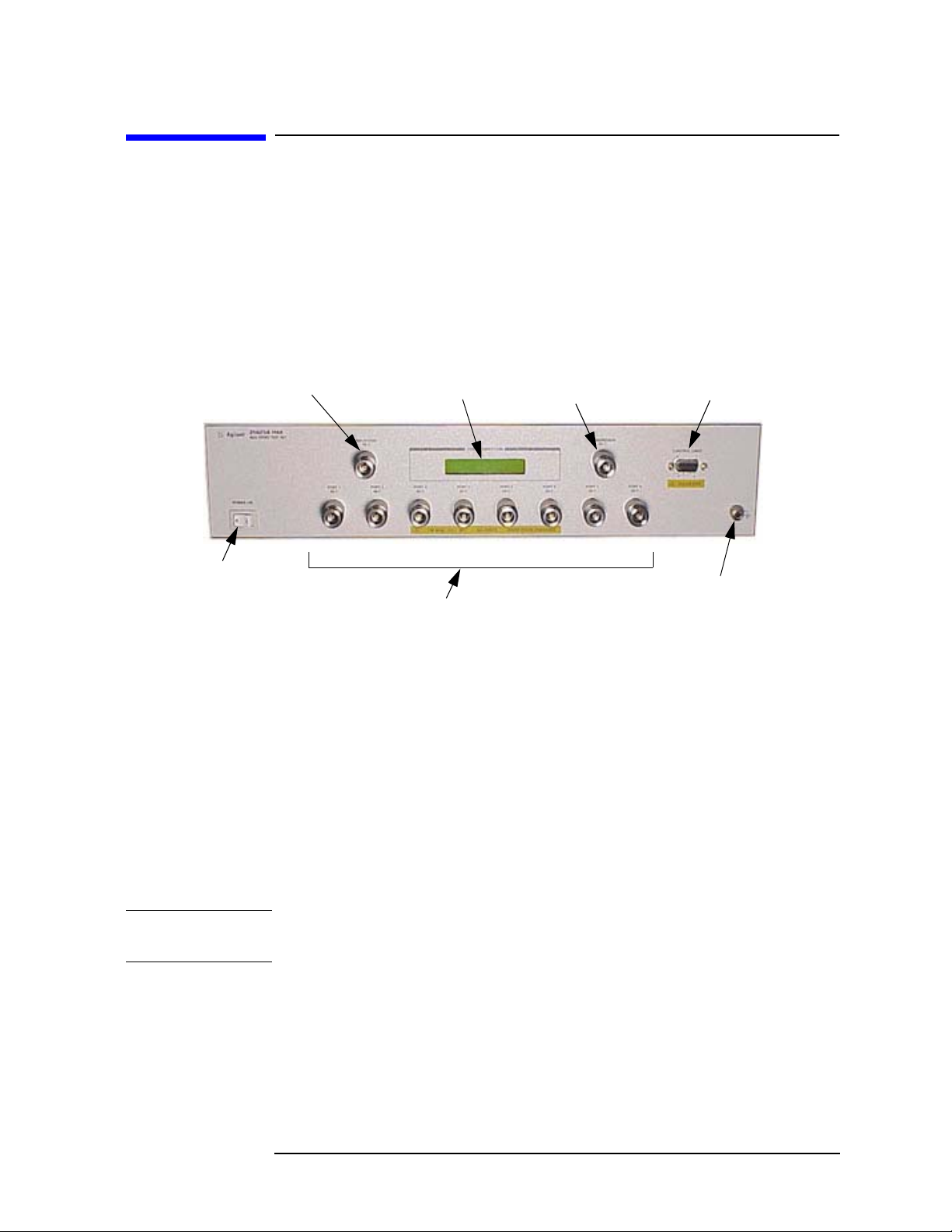
Figure 2-5 Front Panel Features
Installation
Test Set Familiarization
REFLECTION
Port
POWER ON
Switch
POWER ON Switch
The POWER ON Switch turns the AC power to the test set on and off.
The switch is located at the bottom left corner of the front panel. See
Figure 2-5.
The switch disconnects the mains circuits from the mains supply after
the EMC filters and before other parts of the instrument.
PORT
CONNECTION
Status LCD
Test Ports 1 through 8
TRANSMISSION
Port
CONTROL
LINES
Connector
GROUND
Connector
CAUTION
REFLECTION Port, TRANSMISSION Port, and Test Ports 1–8
The REFLECTION Port, the TRANSMISSION Port, and Test Ports 1
through 8 are 50 Ω connectors that are used to connect to the device
under test.
Do not input more than 1 Watt maximum RF+DC to these ports or
damage to the internal RF switches or the analyzer may occur.
The GROUND Connector
The GROUND Connector provides a convenient front panel ground
connection for a standard banana plug.
Agilent Technologies Z5623A Option H48 2 -9
Page 26

Installation
Test Set Familiarization
The PORT CONNECTION Status LCD
The PORT CONNECTION Status LCD displays the following:
• Which test port is connected to the REFLECTION port
• Which test port is connected to the TRANSMISSION port
• The status (O = “Open”, L = “Low”) of each of the five control lines
(C5 through C1)
All test ports not displayed on the Status LCD are internally
terminated in 50 Ω.
The CONTROL LINES Connector
The 9-pin CONTROL LINES Connector provides the user with a way of
controlling either the Device Under Test (DUT) or other equipment. The
test set cannot source any current from this connector. Therefore, the
user must provide an external power supply and some additional
circuitry if he wishes to use the connector. Refer to“Using the Control
Lines Connector” on page 7-6 for further details.
CAUTION
CAUTION
Do not apply more than +22 Vdc to pins 1 through 5 of the CONTROL
LINES Connector.
Do not employ external circuitry that forces the test set to sink more
than 250 mA on any control line (pins 1 through 5 of the CONTROL
LINES Connector) when that line is commanded to the “Low” state
(+0.63 Vdc).
2 -10 Agilent Technologies Z5623A Option H48
Page 27
Rear Panel
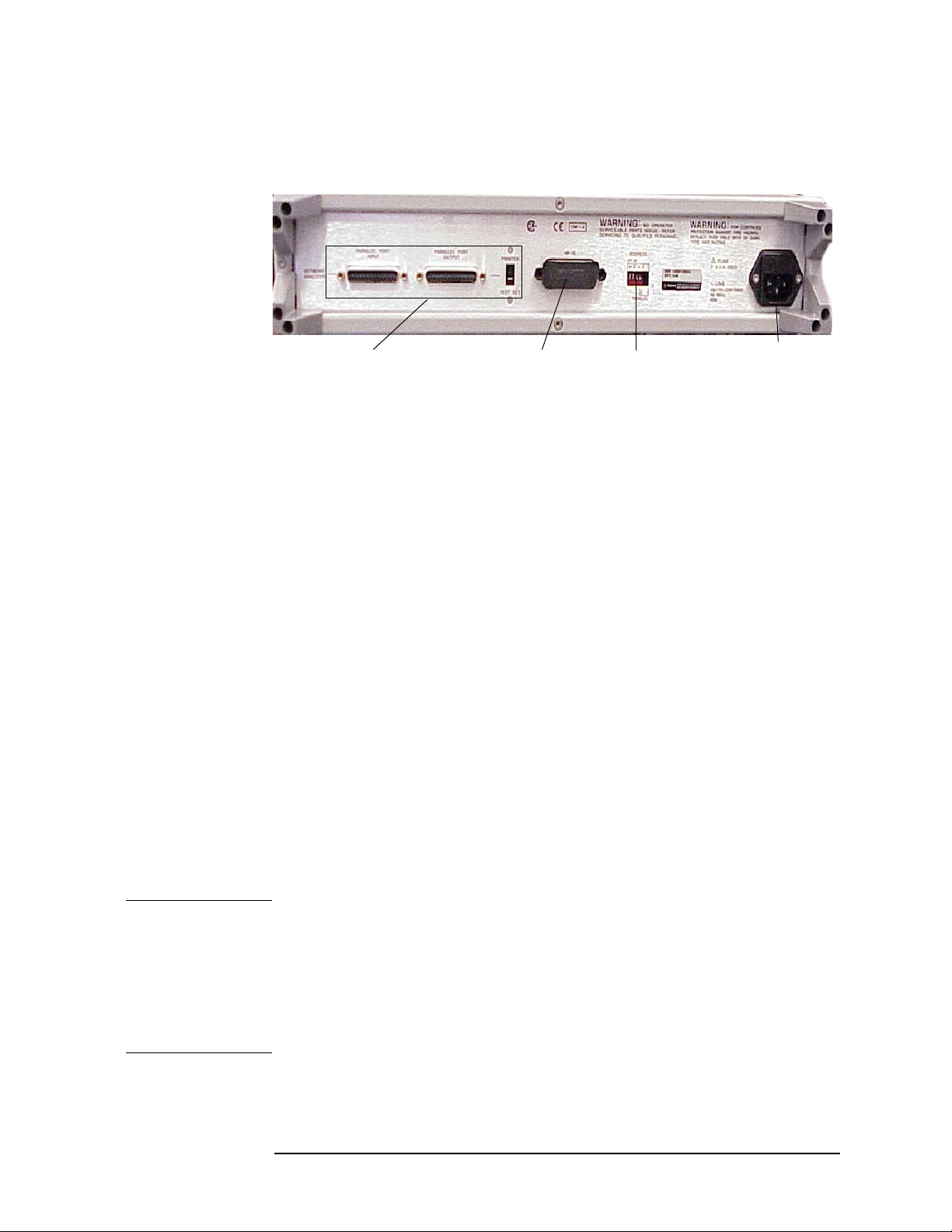
Figure 2-6 Rear Panel Features
Installation
Test Set Familiarization
Not Used
GPIB
Connector
GPIB
Address
Line Module
Switches
GPIB Connector
This connector allows the test set to be controlled either by the network
analyzer or by an external controller.
GPIB Address Switches
The GPIB Address Switches set the GPIB address of the test set. See
“Setting the GPIB Address of the Test Set” on page 2-13 for
information.
Line Module
The line module contains the power cable receptacle and the line fuse.
Power Cables
The line power cable is supplied in one of several configurations,
depending on the destination of the original shipment.
Each instrument is equipped with a three-wire power cable. When
connected to an appropriate ac power receptacle, this cable grounds the
instrument chassis. The type of power cable shipped with each
instrument depends on the country of destination. See Figure 2-2,
“Power Cables,” on page 2-6 for the part numbers of these power cables.
WARNING
This is a Safety Class I product (provided with a protective
earthing ground incorporated in the power cord). The mains
plug shall only be inserted in a socket outlet provided with a
protective earth contact. Any interruption of the protective
conductor, inside or outside the instrument, is likely to make
the instrument dangerous. Intentional interruption is
prohibited.
Agilent Technologies Z5623A Option H48 2 -11
Page 28
Installation
Test Set Familiarization
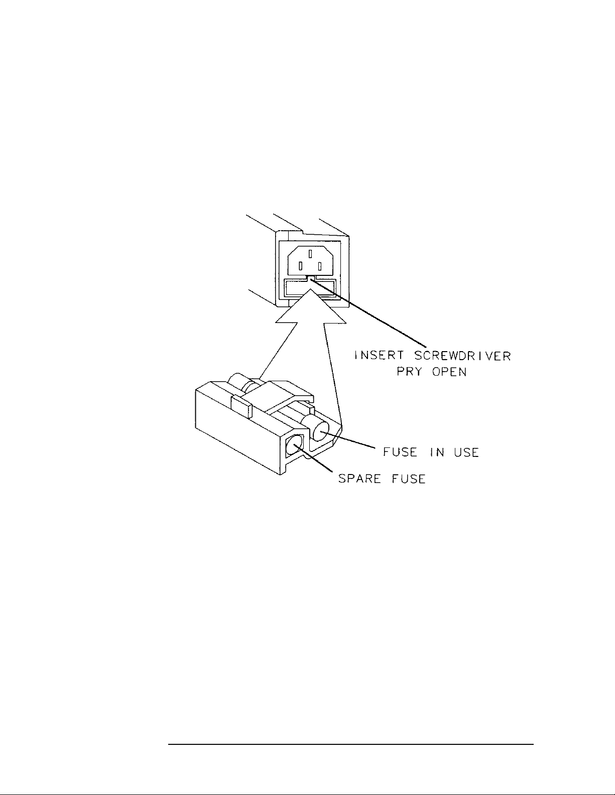
The Line Fuse
The line fuse (F 3 A/250 V, part number 2110-0780) and a spare reside
within the line module. Figure 2-7 illustrates where the fuses are and
how to access them.
Figure 2-7 Location of Line Fuses
2 -12 Agilent Technologies Z5623A Option H48
Page 29
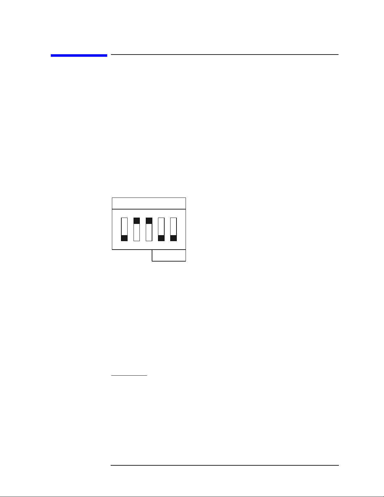
Setting the GPIB Address of the Test Set
A bank of five switches is used to set the GPIB address of the test set.
The switch bank is located on the rear panel of the test set and is shown
in Figure 2-6 on page 2-11. A diagram of the switch bank is presented
in Figure 2-8.
The switch bank sets the GPIB address in binary (base 2) format. Each
switch controls one bit of the address. To set a bit to 1, move the
corresponding switch to the up position. To set a bit to 0, move the
corresponding switch to the down position. The binary address shown
in Figure 2-8 is 01100.
Figure 2-8 GPIB Address Switches
ADDRESS:
HP-IB
168421
Installation
Setting the GPIB Address of the Test Set
Equation 2-1
1
0
12
PARALLEL
To convert the binary address to decimal (base 10) format, just multiply
each bit by the decimal value of that bit, then add the results. The
decimal value of each bit is shown above the corresponding switch.
Applying this conversion method to Figure 2-8 we obtain
016× 0=
18× 8=
14× 4=
02× 0=
02× 0=
Sum 12=
Therefore, the binary GPIB address (01100) shown in Figure 2-8 is
equal to 12 in decimal (base 10) format.
If all bits are set to 1, the GPIB address is 11111 in binary format, or 31
in decimal format. (16 + 8 + 4 + 2 + 1 = 31.) Therefore, the GPIB address
can have any value from 0 to 31 inclusive.
Agilent Technologies Z5623A Option H48 2 -13
Page 30

Installation
Connecting and Turning on the Test Set
NOTE
The test set is shipped from the factory with the GPIB address set to 12.
Connecting and Turning on the Test Set
Make the connections shown in Figure 2-9, “Detailed Equipment
Connection Diagram.” The figure shows two RF cables connecting the
network analyzer to the test set. If you intend to verify the performance
of the test set, use the long RF cables listed in Table 2-3. Otherwise, use
the short ones.
Table 2-3 RF Cables Connecting Network Analyzer to Test Set
Length Part No. Purpose
Long 8120-4781 Verification of test set performance
Short 8120-4782 Measurement of multiport devices
Plug power cords into the test set. Turn both instruments on.
NOTE
Allow the test set to warm up for at least 2 hours. For the most stable
and accurate measurements, leave the test set turned on at all times.
2 -14 Agilent Technologies Z5623A Option H48
Page 31

Connecting and Turning on the Test Set
Figure 2-9 Detailed Equipment Connection Diagram
USB Quad Hub
Port 1 Port 2 Port 3 Port 4
Up Link
Installation
USB Cable
To USB Port
on Rear Panel
To GPIB Connector
on Rear Panel
Port 1
Mouse with
USB Cable
Keyboard with USB Cable
Network Analyzer
USB Port
Port 2
GPIB Cable
To GPIB Connector
on Rear Panel
Agilent Technologies Z5623A Option H48 2 -15
Reflection
Port
1
RF Cables
Z5623A Option H48
Test Ports
2
3
4
Electronic
Calibration
Module
Transmission
Port
8
7
6
5
USB Cable
Page 32

Installation
Connecting and Turning on the Test Set
2 -16 Agilent Technologies Z5623A Option H48
Page 33

3 Using the Network Analyzer to
Control the Test Set
This chapter assumes the following:
• The instructions in Chapter 2 , “Installation,” have been
performed.
• The test set and associated equipment are connected as shown in
Figure 2-9 on page 2-15.
This chapter shows you how the network analyzer can be used to
manually control the test set. The method presented here is considered
a manual one because the user manually enters individual commands
on a keyboard connected to the network analyzer. The chapter includes
the following sections:
• Preparing the Analyzer to Control the Test Set
• How to Send a Manual Command
• Common Errors in Manual Commands
• A List of GPIB Commands
• Restoring the Analyzer to its Normal Configuration
• Disaster Recovery
Agilent Technologies Z5623A Option H48 3-1
Page 34

Using the Network Analyzer to Control the Test Set
Preparing the Analyzer to Control the Test Set
Preparing the Analyzer to Control the Test Set
Step 1. Make sure that all connections shown in Figure 2-9 on page 2-15 have
been made.
Step 2. Make sure that both the PNA Series analyzer and the test set are
turned on.
Step 3. On the network analyzer, click the System menu, scroll down to
Configure, and click SICL/GPIB. See Figure 3-1, “System Menu.”
Figure 3-1 System Menu
3-2 Agilent Technologies Z5623A Option H48
Page 35

Step 4. In the SICL/GPIB window, click System Controller and then OK. See
Figure 3-2, “SICL/GPIB Window.”
Figure 3-2 SICL/GPIB Window
Using the Network Analyzer to Control the Test Set
Preparing the Analyzer to Control the Test Set
Step 5. Locate the Minimize button (“_”) in the top right corner of the window.
See the upper right-hand corner of Figure 3-2. See also the magnified
view shown in Figure 3-3, “Minimize Window.” If the button is not
visible, click on the View menu, then scroll down to Title Bars and click
on it. When the Minimize button is visible, minimize the analyzer
window by clicking on the button.
Figure 3-3 Minimize Window
Click on
Agilent Technologies Z5623A Option H48 3-3
Page 36

Using the Network Analyzer to Control the Test Set
Preparing the Analyzer to Control the Test Set
Step 6. On the desktop, double-click the Measurement & Automation icon.
See Figure 3-4, “PNA DeskTop.”
Figure 3-4 PNA DeskTop
Step 7. From the Measurement & Automation window, click on the Devices
and Interfaces folder to expand the directory.
Step 8. Right
-click GPIBO (AT-GPIB/TNT), then click Interactive Control.
See Figure 3-5, “Interactive Control window.”
Figure 3-5 Interactive Control window
3-4 Agilent Technologies Z5623A Option H48
Page 37

Step 9. When the C:\Progam Files\National Instruments\ NI-488.2\
bin\ibic.exe
window appears, type ibdev. See Figure 3-6, “User
Controller Window.”. Then you will be prompted to:
Enter board index: “0”
Enter primary address: “12”
Enter secondary address: “0”
Enter timeout: “0”
Enter ‘EOI on last byte’ flag: “0”
Enter end-of-string byte/mode: “1”
Figure 3-6 User Controller Window
Using the Network Analyzer to Control the Test Set
Preparing the Analyzer to Control the Test Set
Step 10. If you make a mistake, close the window and repeat steps 7, 8, and 9.
Step 11. When the prompt
ud0: appears in the window, enter ibclr. This
command clears the internal bus. When the ud0: prompt is returned
after the ibclr command has been issued, you are ready to issue
commands to the test set from this window.
Agilent Technologies Z5623A Option H48 3-5
Page 38
Using the Network Analyzer to Control the Test Set
Preparing the Analyzer to Control the Test Set
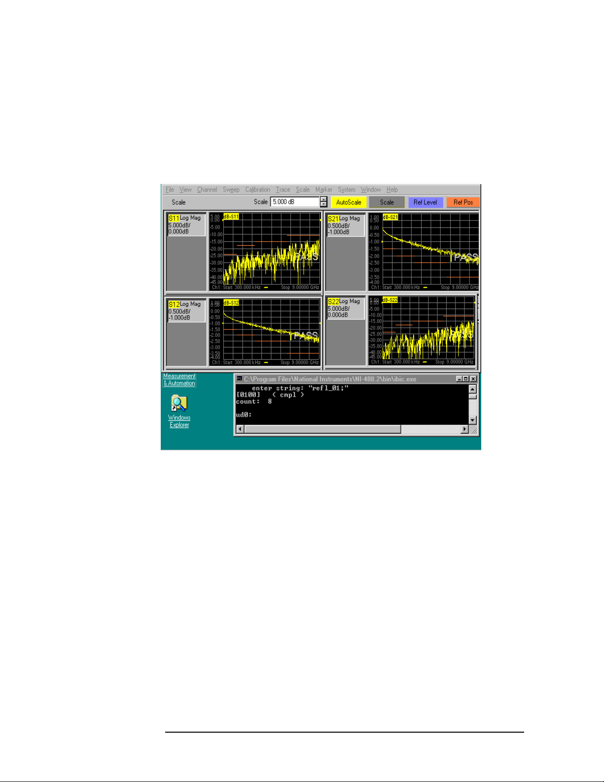
Step 12. Use the mouse to size and position the PNA Series Network Analyzer
window and the command window (
Instruments \NI-488.2\bin\ibic.exe) so that both
visible on the network analyzer screen. See Figure 3-7, “Manual
Control Window.”
Figure 3-7 Manual Control Window
C:\Progam Files\National
windows are
3-6 Agilent Technologies Z5623A Option H48
Page 39

Using the Network Analyzer to Control the Test Set
How to Send a Manual Command
How to Send a Manual Command
This procedure assumes the following:
• The instructions in the previous section (“Preparing the Analyzer
to Control the Test Set”) have been performed.
• The command window (C:\Program Files\
National Instruments\NI-488.2\bin\ibic.exe) shown at the
bottom of Figure 3-7 is visible on the analyzer.
Step 1. Select a command from Table 3-2 or Table 3-3.
Step 2. Click in the command window once to ensure that it is active.
Step 3. Verify that the last line of text appearing in the window is the ud0:
prompt with nothing after it.
Step 4. Type ibwrt and then press the <Enter> key.
NOTE
Step 5. When the prompt enter string: appears, type all
of the following in
exactly the order listed here:
• a double quotation mark (")
• the command selected in Step 1
•a semicolon
• another double quotation mark (")
• the <Enter> key
For example, to connect the Reflection port of the network analyzer to
Test Port #3, type “refl_03;”<Enter>. To connect the Transmission port of
the network analyzer to Test Port #7, type “tran_07;”<Enter>. See Figure
3-6, “User Controller Window.”
Step 6. Look at the PORT CONNECTION display on the test set to verify that
the command was received.
Step 7. If the message on the PORT CONNECTION display is, “ERR: Invalid
Command”, type ibclr<Enter> to clear the bus. Next, repeat Steps 3
through 5.
Use the <Up Arrow> key to recall previous commands. This will
decrease typing time and errors.
NOTE
The test set waits until it receives a semicolon before executing any
command. Once the semicolon is received, the test set combines into a
single string all of the characters it has received since the previous
semicolon. The test set then treats the string as a single command.
Agilent Technologies Z5623A Option H48 3-7
Page 40

Using the Network Analyzer to Control the Test Set
Common Errors in Manual Commands
NOTE
It is possible to issue several commands in a single line. For example,
the following string connects the Reflection port to Test Port #2,
connects the Transmission port to Test Port #5, and sets the Control
Lines to OLOOL: “refl_02;tran_05;00001001;”<Enter>.
Common Errors in Manual Commands
This section explains several common errors.
Table 3-1 Common Errors in Manual Commands
Command(s) Issued Explanation of Error Solution
“refl_01” Missing semicolon. Send a semicolon:
“;”
“refl_01”
“tran_08;”
Missing semicolon in first
command causes both
commands to be interpreted
as a single invalid
command: “refl_01tran_08;”
Resend both
commands with a
semicolon in each:
“refl_01;”
“tran_08;”
“10101;” Three leading zeroes are
missing. (This is a binary
Control Line command. It
needs three leading zeroes.)
(Decimal Control Line
commands don’t need
leading zeroes.)
Resend the command
with leading zeroes
included:
“00010101;”
3-8 Agilent Technologies Z5623A Option H48
Page 41

A List of GPIB Commands
Tab l e 3- 2 Te s t P o rt C om m and s
Connection Path GPIB
Reflection to Port 1 refl_01
Reflection to Port 2 refl_02
Reflection to Port 3 refl_03
Reflection to Port 4 refl_04
Reflection to Port 5 refl_05
Reflection to Port 6 refl_06
Reflection to Port 7 refl_07
Reflection to Port 8 refl_08
Using the Network Analyzer to Control the Test Set
A List of GPIB Commands
Command
NOTE
Transmission to Port 1 tran_01
Transmission to Port 2 tran_02
Transmission to Port 3 tran_03
Transmission to Port 4 tran_04
Transmission to Port 5 tran_05
Transmission to Port 6 tran_06
Transmission to Port 7 tran_07
Transmission to Port 8 tran_08
Reset *rst
Reflection Termination *r_term
Transmission
Termination
All Termination *all_term
*t_term
Every Test Port is connected to one and only one of the following at any
instant:
• Reflection port of the test set.
• Transmission port of the test set.
• 50 Ω termination inside the test set.
Agilent Technologies Z5623A Option H48 3-9
Page 42

Using the Network Analyzer to Control the Test Set
A List of GPIB Commands
Table 3-3 Control Line Commands
GPIB Command
Resulting
Control Line States
(C5, C4, C3, C2, C1)
Mnemonic Decimal Binary
c1_on xxxxL
c1_off xxxxO
c2_on xxxLx
c2_off xxxOx
c3_on xxLxx
c3_off xxOxx
c4_on xLxxx
c4_off xOxxx
c5_on Lxxxx
c5_off Oxxxx
0 00000000 OOOOO
1 00000001 OOOOL
a
2 00000010 OOOLO
3 00000011 OOOLL
4 00000100 OOLOO
5 00000101 OOLOL
6 00000110 OOLLO
7 00000111 OOLLL
8 00001000 OLOOO
9 00001001 OLOOL
10 00001010 OLOLO
11 00001011 OLOLL
12 00001100 OLLOO
13 00001101 OLLOL
14 00001110 OLLLO
15 00001111 OLLLL
16 00010000 LOOOO
3-10 Agilent Technologies Z5623A Option H48
Page 43

Table 3-3 Control Line Commands
Using the Network Analyzer to Control the Test Set
A List of GPIB Commands
GPIB Command
Mnemonic Decimal Binary
17 00010001 LOOOL
18 00010010 LOOLO
19 00010011 LOOLL
20 00010100 LOLOO
21 00010101 LOLOL
22 00010110 LOLLO
23 00010111 LOLLL
24 00011000 LLOOO
25 00011001 LLOOL
26 00011010 LLOLO
27 00011011 LLOLL
28 00011100 LLLOO
Resulting
Control Line States
(C5, C4, C3, C2, C1)
a
29 00011101 LLLOL
30 00011110 LLLLO
31 00011111 LLLLL
a. L = “Low”; O = “Open”; x = “Unchanged”
To connect all test ports to their internal 50 Ω loads, send the following
command:
OUTPUT 712;"*all_term"
Agilent Technologies Z5623A Option H48 3-11
Page 44

Using the Network Analyzer to Control the Test Set
Restoring the Analyzer to its Normal Configuration
Restoring the Analyzer to its Normal
Configuration
It is a good idea to restore the analyzer to its normal configuration once
you are finished using the analyzer to control the test set. To
accomplish this, use the following procedure:
Step 1. Type q in the command window, then press the <Enter> key. This
terminates the interactive control session on the analyzer.
Step 2. In the analyzer window, click System on the menu bar, then scroll
down to Configure, then click SICL/GPIB.
Step 3. In the SICL/GPIB window, click Talke r/ Listener and then OK. This
allows other devices to control the analyzer.
3-12 Agilent Technologies Z5623A Option H48
Page 45

Using the Network Analyzer to Control the Test Set
Disaster Recovery
Disaster Recovery
This section provides recovery procedures for the following problems:
• Malfunctioning Command Window
• Malfunctioning Network Analyzer
Malfunctioning Command Window
Symptoms
Any of the following symptoms indicates a malfunctioning command
window.
• No ud0: prompt is returned when the ibclr command is executed.
• An error message is returned when the ibdev command is
properly executed.
• Upon turning on the network analyzer, the following message
appears: “The device at ‘AT-GPIB/TNT’ cannot be stopped because
a program is still accessing it.”
• When the Recovery Procedure described below is performed, the
“AT-GPIB/TNT” icon observed in Step 6 has a red slash through it
(indicating that the device is presently disabled). However, when
Step 7 is performed, the pop-up menu has “Disable” as a menu
item (indicating that the device is presently enabled!).
Recovery Procedure
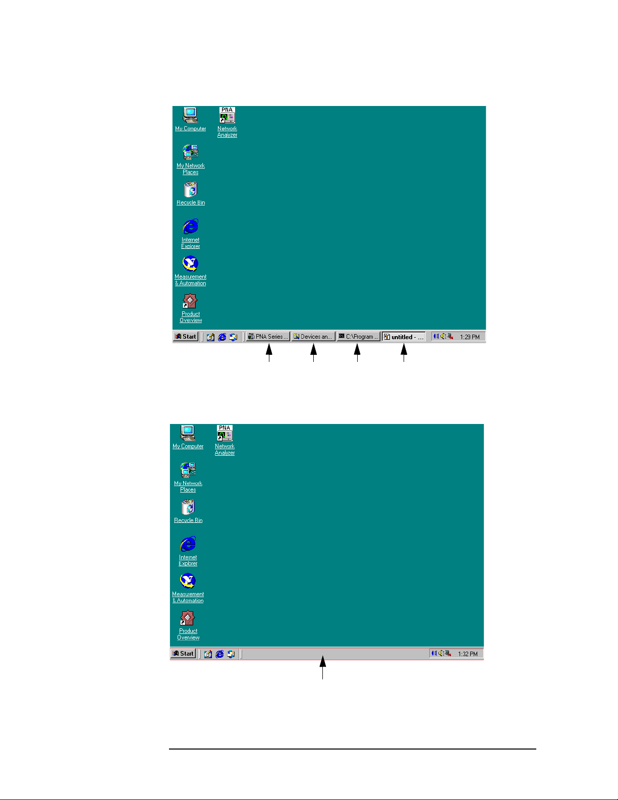
Step 1. Close every application that is running.
a. If an application’s window is open, click on the X in the upper
right-hand corner of the window.
b. If an application’s window has been minimized, locate its icon on the
task bar at the bottom of the network analyzer screen. See Figure
3-8. Click on the icon. This will open the application’s window. Next,
click on the X in the upper right-hand corner of the window to close
the application.
c. When all applications are closed, the task bar will look like the one
in Figure 3-9.
Agilent Technologies Z5623A Option H48 3-13
Page 46
Using the Network Analyzer to Control the Test Set
Disaster Recovery
Figure 3-8 Network Analyzer Screen With Four Applications Running
Four applications running
Figure 3-9 Network Analyzer Screen With No Applications Running
No applications running
3-14 Agilent Technologies Z5623A Option H48
Page 47

Using the Network Analyzer to Control the Test Set
Disaster Recovery
Step 2. Right-click on the “My Computer” icon on the network analyzer screen.
A drop-down menu will appear as shown in Figure 3-10.
Figure 3-10 Analyzer Screen After Right-Click On “My Computer” Icon
Step 3. Click Properties in the drop-down menu. A “System Properties”
window will appear as shown in Figure 3-11.
Figure 3-11 “System Properties” Window
Agilent Technologies Z5623A Option H48 3-15
Page 48

Using the Network Analyzer to Control the Test Set
Disaster Recovery
Step 4. Click the Hardware tab shown in Figure 3-11. The result is shown in
Figure 3-12.
Figure 3-12 “Hardware” Tab In “System Properties” Window
Click this button.
Step 5. Click the Device Manager button. After you do so, there will be a
10-second delay before the “Device Manager” window appears. This
window is shown in Figure 3-13 and Figure 3-14.
Step 6. Check to see if the “AT-GPIB/TNT” icon is visible as shown in Figure
3-14. If it is not, click on the “National Instruments GPIB Interfaces”
icon as in Figure 3-13.
3-16 Agilent Technologies Z5623A Option H48
Page 49

Figure 3-13 Device Manager Window
Using the Network Analyzer to Control the Test Set
Disaster Recovery
Figure 3-14 Device Manager Window With “AT-GPIB/TNT” Icon Visible
Step 7. Right
-click on the “AT-GPIB/TNT” icon. A menu will pop up.
Step 8. Click Disable on the menu.
Step 9. The following message will pop up: “Disabling this device will cause it
to stop functioning. Do you really want to disable it?” Click “Yes.” See
Figure 3-15.
Agilent Technologies Z5623A Option H48 3-17
Page 50

Using the Network Analyzer to Control the Test Set
Disaster Recovery
Figure 3-15 GPIB Device Disabling Message
Step 10. Right
-click on the “AT-GPIB/TNT” icon once again. A menu will pop up.
Step 11. Click Enable on the menu.
Step 12. Close the Device Manager window by clicking on the X in the upper
right-hand corner of the window.
Step 13. Close the System Properties window by clicking on the X in the upper
right-hand corner of the window.
The recovery procedure is now complete. To resume control of the test
set, perform the procedure described in “Preparing the Analyzer to
Control the Test Set” on page 3-2.
Malfunctioning Network Analyzer
Symptoms
Any abnormality in the network analyzer’s behavior indicates a
malfunction of the analyzer. An example would be the failure of icons to
appear on the screen of the analyzer.
Recovery Procedure
Perform a Hard Reset on the PNA Series network analyzer as follows:
First, make sure the power is on (indicated by the power switch being
green). Next, hold the power switch in for about 20 seconds, or until the
color of the switch changes from green to orange. Release the switch,
then press it again and release it immediately.
3-18 Agilent Technologies Z5623A Option H48
Page 51

4 Calibrating the Network
Analyzer
This chapter shows you how to calibrate the network analyzer so that it
can be used to verify the performance of the test set.
The calibration technique presented in this chapter uses an Electronic
Calibration (ECal) Module and is by far the easiest of all 2-port
calibration techniques. Consult the Help facility built into the PNA
Series Network Analyzer for a comprehensive tutorial on this
calibration method and on many others.
This chapter contains the following sections:
• Performing the Calibration
• Renaming the Calibration File
• Recalling and Examining Calibrations
Agilent Technologies Z5623A Option H48 4-1
Page 52

Calibrating the Network Analyzer
Performing the Calibration
Performing the Calibration
Step 1. Make the connections shown in Figure 4-1.
The figure shows two RF cables connecting the two ports of the network
analyzer to the two ports of the ECal Module. The 24” RF cables
(Agilent Part No. 8120-4781 or equivalent) listed in Table 2-2 on
page 2-3 should be used. Make sure the connectors are snugly tightened
but not overtorqued. A torque wrench set to 12 inch-pounds (Agilent
Part No. 8710-1766 or equivalent) is recommended.
Figure 4-1 Calibrating the Network Analyzer
USB Quad Hub
Port 1 Port 2 Port 3 Port 4
Up Link
USB Cable
To USB Port
on Rear Panel
Port 1
Mouse with
USB Cable
Keyboard with USB Cable
Network Analyzer
USB Port
Port 2
RF Cables
Electronic
Calibration
Module
USB Cable
4-2 Agilent Technologies Z5623A Option H48
Page 53

Step 2. Press the Preset button on the Network Analyzer.
Step 3. Verify that the Ready light on the ECal Module is green.
Step 4. On the network analyzer, click Calibration on the menu bar, then click
the Calibration Wizard button. See Figure 4-2.
Figure 4-2 Calibration Menu on Network Analyzer
Calibrating the Network Analyzer
Performing the Calibration
Step 5. When the window shown in Figure 4-3 comes up, click the Cal Type
button. The Cal Type window shown in Figure 4-4 will then pop up.
Figure 4-3 Cal Wizard Window
The currently selected calibration type is “None”.
Agilent Technologies Z5623A Option H48 4-3
Page 54

Calibrating the Network Analyzer
Performing the Calibration
Figure 4-4 Cal Type Window When It Is First Opened
Step 6. Click the Full SOLT 2-Port button. The result is shown in Figure 4-5.
Figure 4-5 Cal Type Window After Selecting “Full SOLT 2-Port”
Step 7. Click the OK button. The Cal Type window will then close and the Cal
Wizard window will pop back up as shown in Figure 4-6.
Figure 4-6 Cal Wizard Menu After Selection Of Cal Type Is Complete
Step 8. Verify that the currently selected calibration type shown in the Cal
Wizard window is “Full SOLT 2-Port (Omit Isolation)” as shown in
Figure 4-6.
Step 9. Click the Measure ECal Stds button in the Cal Wizard window. The
window shown in Figure 4-7 will then pop up.
4-4 Agilent Technologies Z5623A Option H48
Page 55

Figure 4-7 Electronic Calibration Window
Step 10. Click the Module button. The window shown in Figure 4-8 will then
pop up.
Figure 4-8 Module Connection Message
Calibrating the Network Analyzer
Performing the Calibration
Step 11. Click the OK button. (The connections requested in Figure 4-8 were
made in Step 1 of “Performing the Calibration” on page 4-2.) This
window will close, the window shown in Figure 4-7 will pop back up,
and the calibration will begin.
The network analyzer will complete the calibration with no further
operator actions required. The calibration will take about 5 seconds.
Step 12. Verify that the calibration has been completed. This is shown by a check
mark over the Module button as shown in Figure 4-9.
Figure 4-9 Electronic Calibration Window After Cal Is Complete
Step 13. Click the OK button shown in Figure 4-9. The window will close; the
Cal Wizard window will pop back up with the following message as
shown in Figure 4-10: “Done. Save your settings now by pressing OK”.
Agilent Technologies Z5623A Option H48 4-5
Page 56

Calibrating the Network Analyzer
Performing the Calibration
Or repeat your cal.”
Figure 4-10 Cal Wizard Window After Cal Is Complete
Step 14. Get a pen or pencil and a piece of paper. Step 16 will ask you to write
down a filename.
Step 15. Click the OK button. The calibration will now be saved to disk in the
following directory: C:\Program Files\Agilent\Network
Analyzer\Documents. The file will have a “.cst” suffix.
Step 16. Copy down the name of the file into which the calibration is saved. The
name will appear on the screen for about 10 seconds. Copy the filename,
not the path. (The path is listed in Step 15 above.) A typical filename
would be, “at006.cst”. Record also the date and time that the calibration
was performed. (The date and time can be used to locate the file in case
the filename you write down is incorrect or incomplete.)
4-6 Agilent Technologies Z5623A Option H48
Page 57

Renaming the Calibration File
In this section you will rename the calibration file to make it easier to
identify and retrieve.
Step 1. Minimize the network analyzer window. (If you are not sure how to do
this, refer to Step 5 of “Preparing the Analyzer to Control the Test Set”
on page 3-2.)
Step 2. Double-click the “My Computer” icon on the network analyzer display.
This icon can be seen in the upper left-hand corner of Figure 3-8 on
page 3-14.
Step 3. The window shown in Figure 4-11 will pop up. Click the Hard Disk (C:)
icon in that window.
Figure 4-11 “My Computer” Window
Calibrating the Network Analyzer
Renaming the Calibration File
Agilent Technologies Z5623A Option H48 4-7
Page 58

Calibrating the Network Analyzer
Renaming the Calibration File
Step 4. The window shown in Figure 4-12 will pop up. Click the “Program
Files” icon.
Figure 4-12 Root Directory of the C: Drive
Step 5. The window shown in Figure 4-13 will pop up. Click the “Agilent” icon.
Figure 4-13 “C:\Program Files” Directory
4-8 Agilent Technologies Z5623A Option H48
Page 59

Step 6. The window shown in Figure 4-14 will pop up. Click the “Network
Analyzer” icon.
Figure 4-14 “C:\Program Files\Agilent” Directory
Step 7. The window shown in Figure 4-15 will pop up. Click the “Documents”
icon.
Calibrating the Network Analyzer
Renaming the Calibration File
Figure 4-15 “C:\Program Files\Agilent\Network Analyzer” Directory
Agilent Technologies Z5623A Option H48 4-9
Page 60

Calibrating the Network Analyzer
Renaming the Calibration File
Step 8. The window shown in Figure 4-16 will pop up. It contains all of the
calibration files. Click the Type button above the files so that they will
be listed by file type. The result is shown in Figure 4-17.
Figure 4-16 Directory Containing Cal Files
Figure 4-17 Directory Containing Cal Files After Clicking “Type” Button
4-10 Agilent Technologies Z5623A Option H48
Page 61

Step 9. Move the cursor over the filename that was copied down in Step 16 of
“Performing the Calibration” on page 4-6. (If you were not able to copy
down the filename, select the “.cst” file whose date and time correspond
to when you completed the calibration.) Do not
have selected. Just keep the cursor positioned over the filename for
about two seconds (until it is highlighted as shown in Figure 4-18).
Figure 4-18 Cal File Highlighted
Calibrating the Network Analyzer
Renaming the Calibration File
click the filename you
Step 10. Move the cursor off the selected filename (either to the left or to the
right). The selected filename will remain highlighted.
Agilent Technologies Z5623A Option H48 4-11
Page 62

Calibrating the Network Analyzer
Renaming the Calibration File
Step 11. Click File on the menu bar, then scroll down and click the Rename
button as shown in Figure 4-19.
Figure 4-19 Preparing to Rename the Cal File
4-12 Agilent Technologies Z5623A Option H48
Page 63

Step 12. Give the file a new name that includes the following:
• The date the cal was performed
• The suffix “.cst”
For example, if the calibration was performed on 6/17/01, a filename of
“cal_06_17_01.cst” would be appropriate. See Figure 4-20.
Figure 4-20 The Cal File After It Has Been Renamed
Calibrating the Network Analyzer
Renaming the Calibration File
Step 13. Record the new name of the calibration file in Table 4-1. The file must
have a suffix of “.cst”.
Table 4-1 Name of Calibration File
Agilent Technologies Z5623A Option H48 4-13
.cst
Page 64

Calibrating the Network Analyzer
Recalling and Examining Calibrations
Recalling and Examining Calibrations
This section contains the following subsections:
• How to Recall a Calibration
• How to Turn a Calibration On and Off
• How to Examine the Properties of a Calibration
How to Recall a Calibration
There are two methods of recalling a calibration. The first and more
general method is used when the calibration file is not on the “quick
recall” list that appears whenever File is clicked on the menu bar. The
second method is used when the calibration file is on the “quick recall”
list. (This list displays the last eight files that were recalled.)
The examples shown here assume that the desired calibration file is
named, “cal_06_17_01.cst”.
Method 1. Calibration File Is Not On “Quick Recall” List
Step 1. In the network analyzer window, click File on the menu bar, then scroll
down and click the Recall button. See Figure 4-21.
Figure 4-21 File Recall Button
4-14 Agilent Technologies Z5623A Option H48
Page 65

Step 2. The Recall window shown in Figure 4-22 will pop up. Move the
horizontal scroll box until the desired calibration file is visible, then
click on it. The window will momentarily appear as shown in Figure
4-23. The file will then be recalled and the window will close.
Figure 4-22 File Recall Window
Calibrating the Network Analyzer
Recalling and Examining Calibrations
Figure 4-23 File Recall Window After Clicking the Desired Calibration File
Agilent Technologies Z5623A Option H48 4-15
Page 66

Calibrating the Network Analyzer
Recalling and Examining Calibrations
Method 2. Calibration File Is On “Quick Recall” List
Click File on the menu bar, then scroll down to the desired calibration
file and click it. See Figure 4-24. The file will immediately be recalled.
Figure 4-24 Recalling a Calibration File That Is On the “Quick Recall” List
How to Turn a Calibration On and Off
Click Calibration on the menu bar, then scroll down to the
Correction On/Off button.
• If the calibration is turned on, the button will have a check mark in
front of it and the text will read, “Correction ON/off ” as in Figure
4-25.
• If the calibration is turned off, the button will have no
front of it and the text will read, “Correction on/OFF” as in Figure
4-26.
To change from one state to the other, just click the button. Try it! The
trace will change instantaneously. (Compare the trace in Figure 4-25
with the trace in Figure 4-26.)
4-16 Agilent Technologies Z5623A Option H48
check mark in
Page 67

Figure 4-25 Calibration Turned On
Calibrating the Network Analyzer
Recalling and Examining Calibrations
Figure 4-26 Calibration Turned Off
Agilent Technologies Z5623A Option H48 4-17
Page 68

Calibrating the Network Analyzer
Recalling and Examining Calibrations
How to Examine the Properties of a Calibration
Step 1. Click Calibration on the menu bar, then scroll down to the Properties
button and click it. See Figure 4-27.
Figure 4-27 Calibration Properties Button
Step 2. The window shown in Figure 4-28 will pop up. Examine it carefully.
Figure 4-28 Calibration Properties Window
4-18 Agilent Technologies Z5623A Option H48
Page 69

5 Performance Verification
This chapter contains the following sections:
• Setting Test Limits
• Test Strategy
— Insertion Loss
— Return Loss
— Crosstalk
• Setting Up Limit Testing
— Limit Testing for Insertion Loss
— Limit Testing for Return Loss (Port Active)
— Limit Testing for Return Loss (Port Off)
— Limit Testing for Crosstalk
• Verifying Return Loss and Insertion Loss Specifications
• Verifying Crosstalk Specs
Agilent Technologies Z5623A Option H48 5 -1
Page 70

Performance Verification
Setting Test Limits
Setting Test Limits
A test limit is the pass/fail criterion for a measurement. A test limit can
be either a maximum limit or a minimum limit. With a maximum limit,
the measurement must not go above the limit in order for the Device
Under Test (DUT) to pass. With a minimum limit, the measurement
must not go below the limit in order for the DUT to pass.
Test limits are derived from the specifications of the DUT, but are
usually different from them because every measurement has some
uncertainty associated with it. In order to ensure that a performance
specification is met, a “guard band” must be added to account for the
uncertainty in the measurement. This can be done by applying
Equation 5-1.
Equation 5-1 How to Set Test Limits
Test Limit Specification Measurement Uncertainty±=
In Equation 5-1, the plus sign is selected if the limit is a minimum
limit, and the minus sign is selected if the limit is a maximum limit. For
example, if a specification is 20 dB minimum and the measurement
uncertainty is 2 dB, then the test limit should be set to 22 dB. In other
words, the measured value in this example must be 22 dB or greater to
insure that the actual value is 20 dB or greater. Similarly, if a
specification is 20 dB maximum and the measurement uncertainty is 2
dB, then the test limit should be set to 18 dB. In other words, the
measured value in this example must be 18 dB or less to insure that the
actual value is 20 dB or less.
The measurement uncertainties listed in Table 5-1 apply to the
performance tests described in this document. The uncertainties are
derived from the equipment used and the specific measurements
performed.
Table 5-1 Measurement Uncertainties for Performance Verification Tests
Measurement
(dB)
Crosstalk 5 557
Return Loss
(port active)
(300 kHz - 1.3 GHz)
Band 1
1.5 1.0 0.5 0.5
Band 2
(1.3 - 3 GHz)
Band 3
(3 - 6 GHz)
(6 - 9 GHz)
Band 4
Return Loss
(port off)
Insertion Loss 0.3 0.3 0.3 0.3
5 -2 Agilent Technologies Z5623A Option H48
1.5 1.5 1.0 0.5
Page 71

Performance Verification
Setting Test Limits
Applying Equation 5-1 to the uncertainties listed in Table 5-1 and to the
guaranteed specifications listed in Table 1-1 on page 1-4, we obtain the
test limits in Table 5-2:
Table 5-2 Derivation of Test Limits for Performance Verification of Test
Set
Parameter Specification Measurement
Uncertainty
Crosstalk
a,b
Return Loss
(port active)
Return Loss
(port off)
h
Insertion
i
Loss
g
1) –110 dB
2) –105 dB
3) –95 dB
4) –90 dB
1) 24 dB
2) 18 dB
3) 14 dB
4) 9 dB
1) 26 dB
2) 20 dB
3) 16 dB
4) 14 dB
1) 1.5 dB
2) 2.0 dB
3) 2.5 dB
4) 3.5 dB
c
d
e
f
c
d
e
f
c
d
e
f
c
d
e
f
1) 5 dB
2) 5 dB
3) 5 dB
4) 7 dB
1) 1.5 dB
2) 1.0 dB
3) 0.5 dB
4) 0.5 dB
1) 1.5 dB
2) 1.5 dB
3) 1.0 dB
4) 0.5 dB
0.3 dB
(all bands)
c
d
e
f
c
d
e
f
c
d
e
f
Test Limit
1) –115 dB
2) –110 dB
3) –100 dB
4) –97 dB
f
1) 25.5 dB
2) 19 dB
d
3) 14.5 dB
4) 9.5 dB
f
1) 27.5 dB
2) 21.5 dB
3) 17 dB
e
4) 14.5 dB
1) 1.8 dB
2) 2.3 dB
3) 2.8 dB
4) 3.8 dB
c
d
e
f
c
d
e
c
e
c
d
f
a. Between any two non-connected signal paths
b. Conditions: IF Bandwidth = 100 Hertz, Averaging = 10
c. Band 1 (300 kHz to 1.3 GHz)
d. Band 2 (1.3 GHz to 3.0 GHz)
e. Band 3 (3.0 GHz to 6.0 GHz)
f. Band 4 (6.0 GHz to 9.0 GHz)
g. When using an external termination on the Reflection or
Transmission port
h.When using one of the 50 Ω internal terminations
i. From any test set port to the Reflection or Transmission port
Agilent Technologies Z5623A Option H48 5 -3
Page 72

Performance Verification
Test Strategy
Test Strategy
The overall test strategy of this chapter is to verify each guaranteed
specification by means of a limit test that is stored and recalled on the
network analyzer. This strategy minimizes the number of cable
connections and the amount of time required to complete the
performance verification. It also minimizes the likelihood of operator
error.
Whenever one of the limit test files is recalled, it will do the following to
the network analyzer:
• Select the correct S-parameter measurement
• Activate the proper calibration
• Put a title on the screen
•Scale the axes
• Load a limit table
• Display limit lines
• Turn on limit testing
Limit testing tells the user immediately whether the Device Under Test
passes or fails the test. The pass / fail limits are set by the limit table.
In a manner to be described later in this section, the limit table for each
test will be derived from the test limits presented in Table 5-2.
Once the limit test file has been created for a test, the user will run the
test as follows:
• Make the necessary cable connections.
• Issue any needed commands to the test set.
• Recall the limit test file.
Test results will be immediately displayed on the screen of the network
analyzer.
The specifications that are to be verified fall into three general
categories:
• Insertion Loss
• Return Loss
•Crosstalk
The remainder of this section describes, for each category, the Sparameter measurement that will be used to verify the specifications.
The test limits of Table 5-2 will be converted to S-parameter test limits
for each category.
5 -4 Agilent Technologies Z5623A Option H48
Page 73

Performance Verification
Test Strategy
Insertion Loss
For this measurement, Port 1 of the network analyzer will be connected
to one of the test ports of the test set, and Port 2 of the network
analyzer will be connected either to the Reflection port or to the
Transmission port of the test set. By definition,
Insertion Loss = − S
21
where Insertion Loss and S21 are both in units of dB.
The network analyzer will be configured to measure S
. Limit lines
21
will be set up in such a way that each limit equals the negative of the
corresponding insertion loss test limit shown in Table 5-2. For example,
if an insertion loss test limit happens to be 1.0 dB, the corresponding
S
limit will be −1.0 dB.
21
Insertion loss is a maximum spec. Therefore, each S
limit will be set
21
up as a minimum limit. For example, if an insertion loss test limit
happens to be 1.0 dB, the limit table will be set up so that S
above −1.0 dB in order for the instrument to pass. (S
will always be
21
must be
21
zero or negative because the test set provides no amplification. In units
of dB, S
can range from zero to minus infinity.)
21
Return Loss
For this measurement, Port 1 of the network analyzer will be connected
to one of the test ports of the test set, and Port 2 of the network
analyzer will be connected to the Reflection port of the test set. By
definition,
Return Loss = − S
11
where Return Loss and S11 are both in units of dB.
The network analyzer will be configured to measure S
. Limit lines
11
will be set up in such a way that each limit equals the negative of the
corresponding return loss test limit shown in Table 5-2. For example, if
a return loss test limit happens to be 20 dB, the corresponding S
11
limit
will be −20 dB.
Return loss is a minimum spec. Therefore, each S
limit will be set up
11
as a maximum limit. For example, if a return loss test limit happens to
be 20 dB, the limit table will be set up so that S
in order for the instrument to pass. (S
will always be zero or negative
11
because the test set provides no amplification. In units of dB, S
must be below −20 dB
11
can
11
range from zero to minus infinity.)
Agilent Technologies Z5623A Option H48 5 -5
Page 74

Performance Verification
Test Strategy
Return loss is specified for two different conditions:
• Test port active (this means that the test port is internally connected
either to the Reflection port or to the Transmission port)
• Test port off (this means that the test port is internally connected to
a 50-ohm termination)
Return loss is specified for the test ports, but not for the Reflection and
Transmission ports.
Crosstalk
This measurement will be performed between each of the test set’s
pairs of adjacent test ports (1 and 2, 2 and 3, 3 and 4, etc.). The test set
will be commanded to connect its Reflection port to one of the test ports
in the pair, and to connect its Transmission port to the other test port in
the pair. An RF cable will connect Port 1 of the network analyzer to the
Reflection port of the test set. Another RF cable will connect Port 2 of
the network analyzer to the Transmission port of the test set. Network
analyzer calibration will be turned off for this measurement. (The
reason is that the isolation calibration achievable with the Electronic
Calibration module is not good enough.) A Type N 50-ohm male short
will be mounted on each test port in the pair.
The network analyzer will be configured to measure S
Crosstalk = S
21
. By definition,
21
for the setup described above. Limit lines will be set up in such a way
that each S
limit equals the corresponding crosstalk test limit shown
21
in Table 5-2.
Crosstalk is a maximum spec. Therefore, each S
limit will be set up as
21
a maximum limit. For example, if a crosstalk test limit happens to be
−100 dB, the corresponding S
limit will be set up so that S21 must be
21
below −100 dB in order for the instrument to pass.
5 -6 Agilent Technologies Z5623A Option H48
Page 75

Setting Up Limit Testing
In this section, you will create the limit test files described in “Test
Strategy” on page 5-4. As you work through this section, record the
names of the files you create in Table 5-3.
Table 5-3 Limit Test Files
Test Name File Name
Insertion Loss
Return Loss (Port Active)
Return Loss (Port Off)
Crosstalk
This section contains the following subsections:
Performance Verification
Setting Up Limit Testing
• Limit Testing for Insertion Loss
• Limit Testing for Return Loss (Port Active)
• Limit Testing for Return Loss (Port Off)
• Limit Testing for Crosstalk
Agilent Technologies Z5623A Option H48 5 -7
Page 76
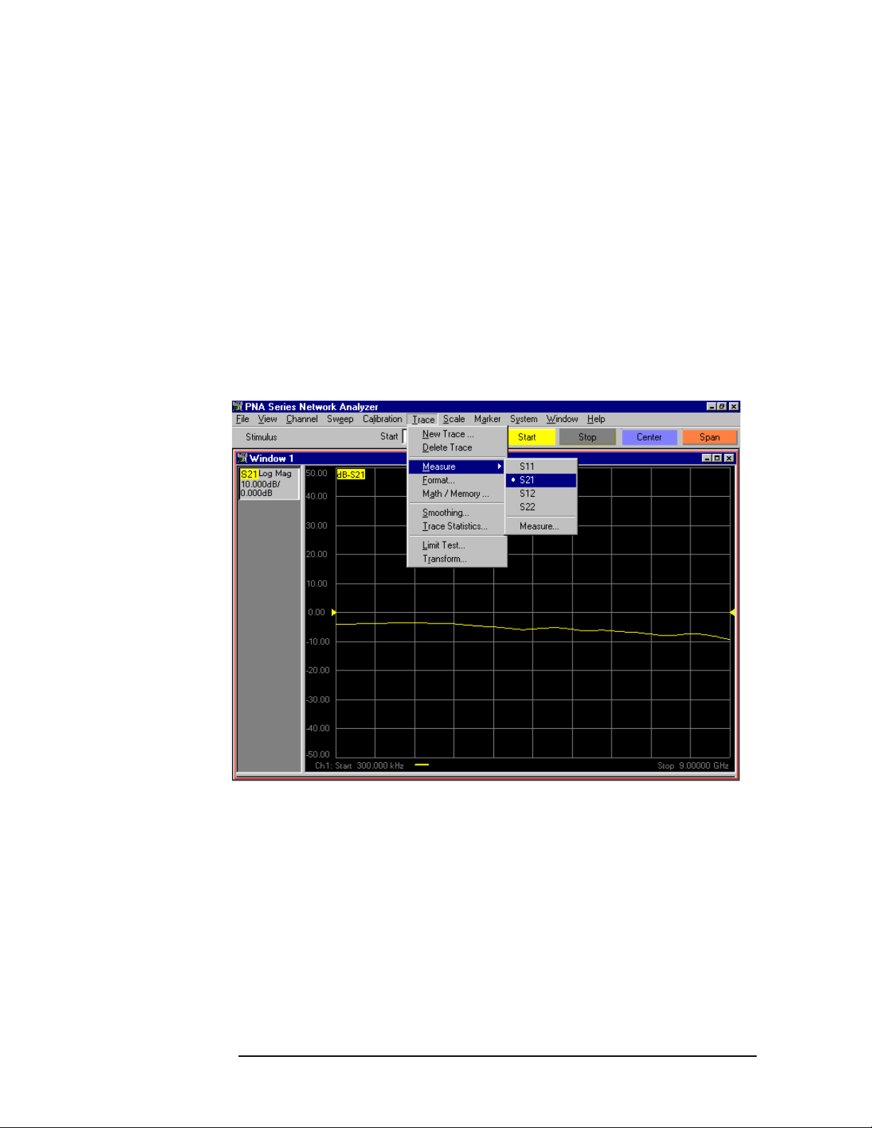
Performance Verification
Setting Up Limit Testing
Limit Testing for Insertion Loss
Recalling the Calibration
Recall the calibration file listed in Table 4-1 on page 4-13. (Consult
“How to Recall a Calibration” on page 4-14.)
Specifying Measurement Type, Title, and Scaling
Step 1. Click Trace on the menu bar. When the Trace menu appears, scroll
down to the Measure button and pause momentarily. When the
Measure menu appears, scroll down to the S21 button and click it. See
Figure 5-1.
Figure 5-1 Specifying an S
Measurement
21
5 -8 Agilent Technologies Z5623A Option H48
Page 77

Step 2. Click View on the menu bar. When the View menu appears, scroll down
to the Meas Display button and pause momentarily. When the Meas
Display menu appears, scroll down to the Title... button and click it.
See Figure 5-2.
Figure 5-2 The “Title...” Button
Performance Verification
Setting Up Limit Testing
Step 3. The Title Entry window is shown in Figure 5-3. When this window pops
up, use the mouse to click anywhere in the white rectangle to the right
of the word, “Entry:”. (The white rectangle is referred to as the Entry
field.) A text entry cursor (a vertical line) will then appear in the white
rectangle.
Figure 5-3 Title Entry Window
Agilent Technologies Z5623A Option H48 5 -9
Page 78

Performance Verification
Setting Up Limit Testing
Step 4. Type “Insertion Loss” in the Entry field as shown in Figure 5-4. You can
do this with the keyboard shown in the Title Entry window if you want,
but an easier way is to use the USB keyboard shown in Figure 2-9 on
page 2-15. After typing “Insertion Loss”, press the Enter key on the
USB keyboard (or the OK button in the Title Entry window) to close the
window and display the new title.
Figure 5-4 Title Entry Window With “Insertion Loss” Entered
Step 5. Click Scale on the menu bar. When the Scale menu appears, scroll
down to the Scale... button and click it. See Figure 5-5.
Figure 5-5 The “Scale...” Button
5 -10 Agilent Technologies Z5623A Option H48
Page 79

Step 6. The Scale window shown in Figure 5-6 will pop up. When it does, set
the following values:
•Scale Per Division = 1 dB
• Reference Level = 0 dB
• Reference Position = 9 Divisions
When these values have been entered, the Scale window will look like
Figure 5-7. Click the OK button.
Figure 5-6 The Scale Window With Default Values
Performance Verification
Setting Up Limit Testing
Figure 5-7 The Scale Window With Desired Values For Insertion Loss
Agilent Technologies Z5623A Option H48 5 -11
Page 80

Performance Verification
Setting Up Limit Testing
Setting Up the Limit Table
Step 1. Click Trace on the menu bar. When the Trace menu appears, scroll
down to the Limit Test... button and click it. See Figure 5-8.
Figure 5-8 The “Limit Test...” Button
Step 2. When the Limit Test window pops up as shown in Figure 5-9, click the
Show Table button, then click the OK button.
Figure 5-9 The “Limit Test” Window
Step 3. When the Limit Table pops up as shown in Figure 5-10, transfer entries
from Table 5-4 to the Limit Table on the network analyzer. The result is
shown in Figure 5-11.
5 -12 Agilent Technologies Z5623A Option H48
Page 81

Performance Verification
Setting Up Limit Testing
Shortcuts:
a. To specify a Segment Type, click the Segment Type box in the
desired row, then use the drop-down menu.
b. To specify a Beginning Stimulus or an Ending Stimulus, click the
respective box in the desired row, then enter the desired value
followed by “k” if the value is in kilohertz, or by “g” if the value is in
gigahertz. For example, to specify a Beginning Stimulus of 300 kHz,
type, “300k” (without the quotation marks). To specify an Ending
Stimulus of 1.3 GHz, type, “1.3g” (without the quotation marks).
c. To specify a Beginning Response or an Ending Response, click the
respective box in the desired row, then enter the desired value in dB,
then hit the space bar. For example, to specify a Beginning Response
of −1.8 dB, type, “−1.8<space>”.
d. Use the tab key to advance from left to right across a row. Use
<shift><tab> to advance from right to left across a row. (When
moving from right to left, the cursor will not move until you release
the shift key.)
Figure 5-10 Empty Limit Table
Table 5-4 Limit Table Entries for Insertion Loss
Segment
Number
1 Min 300 KHz 1.3 GHz −1.8 dB −1.8 dB
2 Min 1.3 GHz 3 GHz −2.3 dB −2.3 dB
3 Min 3 GHz 6 GHz −2.8 dB −2.8 dB
4 Min 6 GHz 9 GHz −3.8 dB −3.8 dB
Limit
Type
Beginning
Stimulus
Ending
Stimulus
Figure 5-11 Completed Limit Table for Insertion Loss
Beginning
Response
Ending
Response
Agilent Technologies Z5623A Option H48 5 -13
Page 82

Performance Verification
Setting Up Limit Testing
Turning On Limit Lines and Limit Testing
Step 1. Click Trace on the menu bar. When the Trace menu appears, scroll
down to the Limit Test... button and click it as shown in Figure 5-8.
The Limit Test window shown in Figure 5-9 will pop up.
Step 2. Click the Limit Test ON and Limit Line ON boxes. The result is
shown in Figure 5-12.
Figure 5-12 Turning On Limit Testing and Limit Line Display
Step 3. Click the Hide Table button, then click the OK button. The result is
shown in Figure 5-13. The trace shown in the figure is an S
21
measurement of the Electronic Calibration (ECal) module. Notice that
the ECal module does not meet the insertion loss specifications of the
test set.
5 -14 Agilent Technologies Z5623A Option H48
Page 83

Performance Verification
Setting Up Limit Testing
Figure 5-13 Insertion Loss Limit Test Being Run On ECal Module
Saving the Limit Test File
Step 1. Click File on the menu bar. When the File menu appears, scroll down to
the Save As... button and click it. See Figure 5-14.
Figure 5-14 “Save As...” Button
Agilent Technologies Z5623A Option H48 5 -15
Page 84

Performance Verification
Setting Up Limit Testing
Step 2. When the Save As window comes up as shown in Figure 5-15, type a file
name that includes the words, “insertion loss,” and the date of the
calibration listed in Table 4-1 on page 4-13. For example, if the
calibration file is named, “cal_06_17_01”, an appropriate file name for
this step would be, “insertion_loss_with_06_17_01_cal”. See Figure
5-16. After entering the file name, record it in Table 5-3 on page 5-7.
Next, click the Save button.
Figure 5-15 “Save As...” Window
Figure 5-16 Specifying The Name Of The Limit Test File For Insertion Loss
5 -16 Agilent Technologies Z5623A Option H48
Page 85

Checking the Limit Test File
Step 1. Connect an RF cable from Port 1 of the network analyzer to Test Port 1
of the test set. Connect an RF cable from Port 2 of the network analyzer
to the Reflection Port of the test set.
Step 2. If the test set is turned off, turn it on. If the test set is already turned
on, turn it off, then back on again. This causes the test set to execute
the “*rst;” command, which is equivalent to the “refl_01;” command
combined with the “tran_08;” command.
Step 3. Recall the calibration file listed in Table 4-1 on page 4-13. (Consult
“How to Recall a Calibration” on page 4-14.) The resulting display
should look something like Figure 5-17.
Figure 5-17 Insertion Loss Test Setup, Cal File Recalled
Performance Verification
Setting Up Limit Testing
Agilent Technologies Z5623A Option H48 5 -17
Page 86

Performance Verification
Setting Up Limit Testing
Step 4. Recall the limit line file for insertion loss. The file name should be listed
in Table 5-3 on page 5-7. The resulting display should look something
like Figure 5-18.
Figure 5-18 Insertion Loss Test Setup, Limit Test File Recalled
5 -18 Agilent Technologies Z5623A Option H48
Page 87

Performance Verification
Setting Up Limit Testing
Limit Testing for Return Loss (Port Active)
Recalling the Calibration
Recall the calibration file listed in Table 4-1 on page 4-13. (Consult
“How to Recall a Calibration” on page 4-14.)
Specifying Measurement Type, Title, and Scaling
The desired measurement type for the Return Loss test is S
network analyzer is already configured to measure S
11
.
. The
11
Step 1. Click View on the menu bar. When the View menu appears, scroll down
to the Meas Display button and pause momentarily. When the Meas
Display menu appears, scroll down to the Title... button and click it.
See Figure 5-2.
Step 2. The Title Entry window is shown in Figure 5-3. When this window pops
up, use the mouse to click anywhere in the white rectangle to the right
of the word, “Entry:”. (The white rectangle is referred to as the Entry
field.) A text entry cursor (a vertical line) will then appear in the white
rectangle.
Step 3. Type “Return Loss (Port Active)” in the Entry field as shown in Figure
5-19. You can do this with the keyboard shown in the Title Entry
window if you want, but an easier way is to use the USB keyboard
shown in Figure 2-9 on page 2-15. After typing “Return Loss (Port
Active)”, press the Enter key on the USB keyboard (or the OK button in
the Title Entry window) to close the window and display the new title.
Figure 5-19 Title Entry Window With “Return Loss (Port Active)” Entered
Step 4. Click Scale on the menu bar. When the Scale menu appears, scroll
down to the Scale... button and click it. See Figure 5-5.
Agilent Technologies Z5623A Option H48 5 -19
Page 88

Performance Verification
Setting Up Limit Testing
Step 5. The Scale window shown in Figure 5-6 will pop up. When it does, set
the following values:
•Scale Per Division = 5 dB
• Reference Level = 0 dB
• Reference Position = 9 Divisions
When these values have been entered, the Scale window will look like
Figure 5-20. Click the OK button.
Figure 5-20 The Scale Window With Desired Values For Return Loss
Setting Up the Limit Table
Step 1. Click Trace on the menu bar. When the Trace menu appears, scroll
down to the Limit Test... button and click it. See Figure 5-8.
Step 2. When the Limit Test window pops up as shown in Figure 5-9, click the
Show Table button, then click the OK button.
Step 3. When the Limit Table pops up as shown in Figure 5-10, transfer entries
from Table 5-5 to the Limit Table on the network analyzer. (Consult the
shortcuts listed on page 5-13.) The result is shown in Figure 5-21.
Table 5-5 Limit Table Entries for Return Loss (Port Active)
Segment
Number
1 Max 300 kHz 1.3 GHz −25.5 dB −25.5 dB
2 Max 1.3 GHz 3 GHz −19 dB −19 dB
3 Max 3 GHz 6 GHz −14.5 dB −14.5 dB
4 Max 6 GHz 9 GHz −9.5 dB −9.5 dB
Segment
Type
Beginning
Stimulus
Ending
Stimulus
Beginning
Response
Ending
Response
5 -20 Agilent Technologies Z5623A Option H48
Page 89

Performance Verification
Setting Up Limit Testing
Figure 5-21 Completed Limit Table for Return Loss (Port Active)
Turning On Limit Lines and Limit Testing
Step 1. Click Trace on the menu bar. When the Trace menu appears, scroll
down to the Limit Test... button and click it as shown in Figure 5-8.
The Limit Test window shown in Figure 5-9 will pop up.
Step 2. Click the Limit Test ON and Limit Line ON boxes. The result is
shown in Figure 5-12.
Step 3. Click the Hide Table button, then click the OK button. The result is
shown in Figure 5-22. The trace shown in the figure is an S
measurement of the Electronic Calibration (ECal) module. Notice that
the ECal module does not meet the return loss specifications of the test
set.
11
Figure 5-22 Return Loss (Port Active) Limit Test On ECal Module
Agilent Technologies Z5623A Option H48 5 -21
Page 90

Performance Verification
Setting Up Limit Testing
Saving the Limit Test File
Step 1. Click File on the menu bar. When the File menu appears, scroll down to
the Save As... button and click it. See Figure 5-14.
Step 2. When the Save As window comes up as shown in Figure 5-15, type a file
name that includes the words, “return loss,” the words, “port active”,
and the date of the calibration listed in Table 4-1 on page 4-13. For
example, if the calibration file is named, “cal_06_17_01”, an appropriate
file name for this step would be, “return_loss_port_active_with_
06_17_01_cal”. See Figure 5-16. After entering the file name, record it
in Table 5-3 on page 5-7. Next, click the Save button.
Checking the Limit Test File
Step 1. Connect an RF cable from Port 1 of the network analyzer to Test Port 1
of the test set. Connect an RF cable from Port 2 of the network analyzer
to the Reflection Port of the test set.
Step 2. If the test set is turned off, turn it on. If the test set is already turned
on, turn it off, then back on again. This causes the test set to execute
the “*rst;” command, which is equivalent to the “refl_01;” command
combined with the “tran_08;” command.
Step 3. Recall the calibration file listed in Table 4-1 on page 4-13. (Consult
“How to Recall a Calibration” on page 4-14.) The resulting display
should look something like Figure 5-17.
5 -22 Agilent Technologies Z5623A Option H48
Page 91

Performance Verification
Setting Up Limit Testing
Step 4. Recall the limit line file for return loss (port active). The file name
should be listed in Table 5-3 on page 5-7. The resulting display should
look something like Figure 5-23.
Figure 5-23 Return Loss (Port Active) Test Setup, Limit Test File Recalled
Agilent Technologies Z5623A Option H48 5 -23
Page 92

Performance Verification
Setting Up Limit Testing
Limit Testing for Return Loss (Port Off)
The limit test for return loss (port off) is identical to the limit test for
return loss (port active) with the following exceptions:
•The title
• The limit table
Recalling the “Port Active” Limit Test File
Recall the limit test file for return loss (port active). It should be
recorded in Table 5-3 on page 5-7.
Specifying the Title
Step 1. Click View on the menu bar. When the View menu appears, scroll down
to the Meas Display button and pause momentarily. When the Meas
Display menu appears, scroll down to the Title... button and click it.
See Figure 5-2.
Step 2. The Title Entry window is shown in Figure 5-3. When this window pops
up, click in the Entry field.
Step 3. Type “Return Loss (Port Off)” in the Entry field, then press the Enter
key on the USB keyboard (or the OK button in the Title Entry window)
to close the window and display the new title.
Setting Up the Limit Table
Step 1. Click Trace on the menu bar. When the Trace menu appears, scroll
down to the Limit Test... button and click it. See Figure 5-8.
Step 2. When the Limit Test window pops up as shown in Figure 5-9, click the
Show Table button, then click the OK button.
Step 3. When the Limit Table pops up, transfer entries from Table 5-6 to the
Limit Table on the network analyzer. (Consult the shortcuts listed on
page 5-13.) The result is shown in Figure 5-24.
Table 5-6 Limit Table Entries for Return Loss (Port Off)
Segment
Number
1 Max 300 kHz 1.3 GHz −27.5 dB −27.5 dB
2 Max 1.3 GHz 3 GHz −21.5 dB −21.5 dB
3 Max 3 GHz 6 GHz −17 dB −17 dB
Segment
Type
Begin
Stimulus
End
Stimulus
Begin
Response
End
Response
4 Max 6 GHz 9 GHz −14.5 dB −14.5 dB
5 -24 Agilent Technologies Z5623A Option H48
Page 93

Setting Up Limit Testing
Figure 5-24 Completed Limit Table for Return Loss (Port Off)
Step 4. Click Trace on the menu bar. When the Trace menu appears, scroll
down to the Limit Test... button and click it as shown in Figure 5-8.
The Limit Test window shown in Figure 5-9 will pop up.
Step 5. Click the Hide Table button, then click the OK button.
Saving the Limit Test File
Step 1. Click File on the menu bar. When the File menu appears, scroll down to
the Save As... button and click it. See Figure 5-14.
Performance Verification
Step 2. When the Save As window comes up as shown in Figure 5-15, type a file
name that includes the words, “return loss,” the words, “port off”, and
the date of the calibration listed in Table 4-1 on page 4-13. For example,
if the calibration file is named, “cal_06_17_01”, an appropriate file
name for this step would be, “return_loss_port_off_with_ 06_17_01_cal”.
See Figure 5-16. After entering the file name, record it in Table 5-3 on
page 5-7. Next, click the Save button.
Recalling the Limit Test File
Recall the limit test file that you have just saved. (Consult “How to
Recall a Calibration” on page 4-14.) This will put it on the “Quick
Recall” list.
Agilent Technologies Z5623A Option H48 5 -25
Page 94

Performance Verification
Setting Up Limit Testing
Limit Testing for Crosstalk
Specifying Output Power
Step 1. Press the Preset button.
Step 2. Click Channel on the menu bar. When the Channel menu appears,
scroll down to the Power... button and click it. See Figure 5-25.
Figure 5-25 The “Power...” Button
5 -26 Agilent Technologies Z5623A Option H48
Page 95

Step 3. The Power window shown in Figure 5-26 will pop up. Set the Test Port
Power to +10 dBm as shown in Figure 5-27. Click the OK button in the
Power window.
Figure 5-26 Power Window with Default Values
Performance Verification
Setting Up Limit Testing
Figure 5-27 Power Window with Values Desired for Crosstalk
Agilent Technologies Z5623A Option H48 5 -27
Page 96

Performance Verification
Setting Up Limit Testing
Specifying IF Bandwidth and Averaging
Step 1. Click Sweep on the menu bar. When the Sweep menu appears, scroll
down to the IF Bandwidth... button and click it. See Figure 5-28.
Figure 5-28 The “IF Bandwidth...” Button
Step 2. When the IF Bandwidth window pops up as shown in Figure 5-29,
change the IF Bandwidth to 100Hz. (Type, “100<space>”, without the
quotation marks.) The result is shown in Figure 5-30. Click the OK
button.
Figure 5-29 IF Bandwidth Window with Default Value
5 -28 Agilent Technologies Z5623A Option H48
Page 97

Performance Verification
Setting Up Limit Testing
Figure 5-30 IF Bandwidth Window with Value Desired for Crosstalk
Step 3. Click Channel on the menu bar. When the Channel menu appears,
scroll down to the Average... button and click on it. See Figure 5-31.
Figure 5-31 The “Average...” Button
Agilent Technologies Z5623A Option H48 5 -29
Page 98

Performance Verification
Setting Up Limit Testing
Step 4. When the Average window shown in Figure 5-32 appears, click the
Average ON box. Next, change the Average Factor to 10. (It is best to
change the Average Factor by using the up arrow.) The results are
shown in Figure 5-33. Click the OK button.
Figure 5-32 Average Window with Default Settings
Figure 5-33 Average Window with Settings Desired for Crosstalk
5 -30 Agilent Technologies Z5623A Option H48
Page 99

Step 5. Click View on the menu bar. When the View menu appears, scroll down
to the Status Bar button and click it as shown in Figure 5-34. The
status bar will appear at the bottom of the screen as shown in Figure
5-35.
Figure 5-34 The “Status Bar” Button
Performance Verification
Setting Up Limit Testing
Agilent Technologies Z5623A Option H48 5 -31
Page 100

Performance Verification
Setting Up Limit Testing
Figure 5-35 The Status Bar Displayed at Bottom of Screen
Specifying Measurement Type, Title, and Scaling
Step 1. Click Trace on the menu bar. When the Trace menu appears, scroll
down to the Measure button and pause momentarily. When the
Measure menu appears, scroll down to the S21 button and click it. See
Figure 5-1.
Step 2. Click View on the menu bar. When the View menu appears, scroll down
to the Meas Display button and pause momentarily. When the Meas
Display menu appears, scroll down to the Title... button and click it.
See Figure 5-2.
Step 3. The Title Entry window is shown in Figure 5-3. When this window pops
up, click in the Entry field.
Step 4. Type “Crosstalk” in the Entry field, then press the Enter key on the
USB keyboard (or the OK button in the Title Entry window) to close the
window and display the new title.
Step 5. Click Scale on the menu bar. When the Scale menu appears, scroll
down to the Scale... button and click it. See Figure 5-5.
5 -32 Agilent Technologies Z5623A Option H48
 Loading...