

Page 1

e
Xcalibur
Gemini
(including Ultra)
Single Crystal Diffractometers
User Manual
Version 2.4, September 2011
Agilent Technologies XRD Products
10 Mead Road, Yarnton, Oxfordshire. OX5 1QU, UK
Tel: +44(0)1865 291600
Fax: +44 (0)1865 291601
http://www.agilent.com/chem
Page 2

Notices
CAUTION
WARNING
© Agilent Technologies, Inc. 2011
No part of this manual may be
reproduced in any form or by any means
(including electronic storage and retrieval
or translation into a foreign language)
without prior agreement and written
consent from Agilent Technologies, Inc.
as governed by United States and
international copyright laws.
For Assistance and Support
http://www.agilent.com/find/assist
Limitation of Warranty
The foregoing warranty shall not apply to
defects resulting from improper or
inadequate maintenance by Buyer, Buyersupplied software or interfacing,
unauthorized modification or misuse,
operation outside of the environmental
specifications for the product, or improper
site preparation or maintenance. No other
warranty is expressed or implied. Agilent
Technologies specifically disclaims the
implied warranties of Merchantability and
Fitness for a Particular Purpose.
Warranty
The material contained in this document
is provided “as is,” and is subject to
being changed, without notice, in future
editions. Further, to the maximum extent
permitted by applicable law, Agilent
disclaims all warranties, either express
or implied, with regard to this manual
and any information contained herein,
including but not limited to the implied
warranties of merchantability and
fitness for a particular purpose. Agilent
shall not be liable for errors or for
incidental or consequential damages in
connection with the furnishing, use, or
performance of this document or of any
information contained herein. Should
Agilent and the user have a separate
written agreement with warranty terms
covering the material in this document
that conflict with these terms, the
warranty terms in the separate
agreement shall control.
Technology Licenses
The hardware and/or software described
in this document are furnished under a
license and may be used or copied only in
accordance with the terms of such
license.
Restricted Rights Legend
If software is for use in the performance
of a U.S. Government prime contract or
subcontract, Software is delivered and
licensed as “Commercial computer
software” as defined in DFAR 252.2277014 (June 1995), or as a “commercial
item” as defined in FAR 2.101(a) or as
“Restricted computer software” as
defined in FAR 52.227-19 (June 1987) or
any equivalent agency regulation or
contract clause. Use, duplication or
disclosure of Software is subject to
Agilent Technologies‟ standard
commercial license terms, and non-DOD
Departments and Agencies of the U.S.
Government will receive no greater than
Restricted Rights as defined in FAR
52.227-19(c)(1-2) (June 1987). U.S.
Government users will receive no greater
than Limited Rights as defined in FAR
52.227-14 (June 1987) or DFAR 252.2277015 (b)(2) (November 1995), as
applicable in any technical data.
Safety Notices
A CAUTION notice denotes a
hazard. It calls attention to an
operating procedure, practice, or
the like that, if not correctly
performed or adhered to, could
result in damage to the product
or loss of important data. Do not
proceed beyond a CAUTION
notice until the indicated
conditions are fully understood
and met.
A WARNING notice denotes a
hazard. It calls attention to an
operating procedure, practice,
or the like that, if not correctly
performed or adhered to, could
result in personal injury or
death. Do not proceed beyond a
WARNING notice until the
indicated conditions are fully
understood and met.
Page 3

Safety Summary
General Safety
Precautions
The following general safety precautions
must be observed during all phases of
operation of this instrument. Failure to
comply with these precautions or with
specific warnings elsewhere in this
manual violates safety standards of
design, manufacture, and intended use of
the instrument.
Agilent Technologies Inc. assumes no
liability for the customer's failure to
comply with these requirements.
Before operation, review the instrument
and manual for safety markings and
instructions. You must follow these to
ensure safe operation and to maintain the
instrument in safe condition.
General
This product is a Safety Class 1
instrument (provided with a protective
earth terminal). The protective features of
this product may be impaired if it is used
in a manner not specified in the operation
instructions.
Environment Conditions
This instrument is intended for indoor use
in an installation category II, pollution
degree 2 environment.
Refer to the specifications tables for the
ac mains voltage requirements and
ambient operating temperature range.
Before Applying Power
Verify that all safety precautions are
taken. The power cable inlet of the
instrument serves as a device to
disconnect from the mains in case of
hazard. The instrument must be
positioned so that the operator can easily
access the power cable inlet. When the
instrument is rack mounted the rack must
be provided with an easily accessible
mains switch.
Ground the Instrument
To minimize shock hazard, the instrument
chassis and cover must be connected to
an electrical protective earth ground. The
instrument must be connected to the ac
power mains through a grounded power
cable, with the ground wire firmly
connected to an electrical ground (safety
ground) at the power outlet. Any
interruption of the protective (grounding)
conductor or disconnection of the
protective earth terminal will cause a
potential shock hazard that could result in
personal injury.
Do Not Operate in an
Explosive Atmosphere
Do not operate the instrument in the
presence of flammable gases or fumes.
Do Not Remove the
Instrument Cover
Operating personnel must not remove
instrument covers. Component
replacement and internal adjustments
must be made only by qualified
personnel.
Instruments that appear damaged or
defective should be made inoperative and
secured against unintended operation
until they can be repaired by qualified
service personnel.
Page 4
This product complies with the WEEE
Directive (2002/96/EC) marketing
requirements. The affixed label indicates
that you must not discard this
electrical/electronic product in domestic
household waste.
Do not dispose in domestic household
waste.
To return unwanted products, contact
your local Agilent office, or see
www.agilent.com/environment/product/
for more information.
Environmental Information
Page 5

Important Information
Product:
Xcalibur or Gemini
Model
Configuration:
X-ray source: ENHANCE and/or ULTRA
Detector: Eos, Atlas or Titan
Electrical Ratings:
1/N AC 230 V 50/60 Hz 4200 Watts
This user manual applies to the Xcalibur systems manufactured in Poland by Agilent Technologies.
Before attempting to operate the system, PLEASE READ THE INSTRUCTIONS.
This product should only be used by persons legally permitted to do so.
If the equipment is used in a manner not specified in the User Manual, the protection provided by the
equipment may be impaired.
Important Health and Safety Notice
When returning components for service or repair it is essential that the item is shipped together with
a signed declaration that the product has not been exposed to any hazardous contamination or that
appropriate decontamination procedures have been carried out so that the product is safe to handle.
Care has been taken to ensure the information in this manual is accurate and at an appropriate level.
Please inform Agilent Technologies if you have any suggestions for corrections or improvements to
this manual.
Xcalibur service and support is available for technical and operational issues as indicated below.
E-mail: XRDSupport@agilent.com
Phone: +44 (0)1865 291600 between 8 a.m. and 4.30 p.m. (UK time), Monday to Friday
Fax: +44 (0)1865 291601
Agilent Technologies acknowledges all trademarks and registrations.
Copyright 2011 Agilent Technologies Limited. All rights reserved. No part of this document may be
reproduced or distributed in any form, or by any means, or stored in a database or retrieval system,
without prior written permission of Agilent Technologies.
Xcalibur/Gemini Version 2.4
USER MANUAL Page v
Page 6

Contents
1. Health and Safety Information .............................................................................. 1
1.1 General ......................................................................................................................................................... 1
1.2 Electrical Safety .......................................................................................................................................... 2
1.2.1. Potential Electrical Hazards ........................................................................................................... 2
1.2.2. Recommended Precautions ........................................................................................................... 2
1.2.3. First Aid ............................................................................................................................................. 3
1.3 Mechanical Handling Safety ..................................................................................................................... 3
1.4 Safe Mechanical Practice ......................................................................................................................... 3
1.5 Moving Parts ............................................................................................................................................... 4
1.6 Extreme Temperatures .............................................................................................................................. 4
1.7 X-ray Radiation ............................................................................................................................................ 4
1.8 Vacuum ........................................................................................................................................................ 5
1.9 High Pressures ............................................................................................................................................ 5
1.10 Hazardous or Toxic Materials ................................................................................................................ 6
1.11 Maintenance ............................................................................................................................................. 6
2. Introduction ............................................................................................................. 7
2.1 Scope ............................................................................................................................................................ 7
2.2 How To Use This Manual .......................................................................................................................... 7
2.3 System Overview ........................................................................................................................................ 7
3. Specifications ......................................................................................................... 8
3.1 Environmental Requirements ................................................................................................................... 8
3.2 Services ........................................................................................................................................................ 8
3.2.1. Electrical Supply .............................................................................................................................. 8
3.2.2. Water Cooling .................................................................................................................................. 9
3.2.3. Helium Gas Supply For Ultra .......................................................................................................... 9
3.3 Performance Data ..................................................................................................................................... 10
3.3.1. X-ray Tube (Typical Operating Conditions) ............................................................................... 10
3.3.2. CCD Detector .................................................................................................................................. 10
3.3.2.1 General .......................................................................................................................................... 10
3.3.2.2 Eos CCD Detector ........................................................................................................................ 11
3.3.2.3 Atlas CCD Detector ..................................................................................................................... 11
3.3.2.4 Titan CCD Detector ..................................................................................................................... 11
3.3.2.5 PC CCD Interface ......................................................................................................................... 11
3.3.2.6. CCD Detector Maximum Theta and Resolution .................................................................... 12
3.3.2.7. CCD Detector Maximum Distance ........................................................................................... 13
3.3.3. Four-circle Kappa Geometry X-ray Goniometer ........................................................................ 14
3.4 Electrical Data ........................................................................................................................................... 14
4. Technical Description .......................................................................................... 15
4.1 Overview of Xcalibur/Gemini ................................................................................................................. 15
4.2 KMW200CCD Chiller and KMW3000C Chiller...................................................................................... 18
4.3 Low Temperature Option ......................................................................................................................... 18
4.4 Safety Features ......................................................................................................................................... 18
5. Handling, Installation, Storage and Transit Information ................................. 20
Xcalibur/Gemini Version 2.4
USER MANUAL Page vi
Page 7

5.1 Reception and Handling .......................................................................................................................... 20
5.1.1. Delivery ............................................................................................................................................ 20
5.1.2. Unpacking ....................................................................................................................................... 20
5.1.3. Mechanical Handling .................................................................................................................... 21
5.2 Installation and Setting to Work ............................................................................................................ 22
5.2.1. Preparation of Site and Services ................................................................................................ 22
5.2.2. Setting to Work .............................................................................................................................. 25
5.3 Storage ....................................................................................................................................................... 25
6. Operation ............................................................................................................... 26
6.1 Controls and Indicators ........................................................................................................................... 26
6.2 System Start-Up ........................................................................................................................................ 28
6.3 X-ray Tube Warm-up Procedure ............................................................................................................ 29
6.4 System Standby and Normal Shutdown Procedure ........................................................................... 29
6.5 Emergency Shutdown .............................................................................................................................. 30
6.5.1. Emergency Shutdown Procedure ............................................................................................... 30
7. Maintenance Schedules ...................................................................................... 31
7.1 Introduction ............................................................................................................................................... 31
7.2 Weekly Maintenance Schedule ............................................................................................................. 31
7.3 Monthly Maintenance Schedule ............................................................................................................ 31
7.4 Six Monthly Maintenance Schedule ..................................................................................................... 32
7.5 Yearly Maintenance Schedule ................................................................................................................ 32
7.6 10,000 Hours Maintenance Schedule ................................................................................................... 32
8. Maintenance Instructions ................................................................................... 34
8.1 Refining the Machine Parameter File ................................................................................................... 34
8.2 Changing the X-ray Tube of Ultra (Horizontal X-ray tubes) ............................................................... 35
8.3 Changing the X-ray Tube of Enhance (Vertical X-ray Tubes)............................................................ 37
8.4 Changing the Collimator of Enhance ..................................................................................................... 38
8.5 Aligning the X-ray Collimator of Enhance ............................................................................................ 39
8.6 Aligning the Video Microscope .............................................................................................................. 39
8.7 Checking the Door Safety Interlocks ..................................................................................................... 41
8.8 Checking the Emergency stop ................................................................................................................ 41
8.9 Checking the X-ray Radiation Levels ..................................................................................................... 42
8.10 CCD Detector – Pumping Out Vacuum ............................................................................................... 42
9. Trouble Shooting .................................................................................................. 45
10. Spares .................................................................................................................. 52
10.1 Fuses......................................................................................................................................................... 52
10.2 Bulbs ......................................................................................................................................................... 52
11. Disposal Instructions ......................................................................................... 53
11.1 X-ray Tube and CCD Detector .............................................................................................................. 53
11.2 Third Party Equipment ........................................................................................................................... 53
12. Additional Information ....................................................................................... 54
12.1 Third Party Information.......................................................................................................................... 54
12.2 Drawings .................................................................................................................................................. 55
12.2.1. Mechanical Drawings ................................................................................................................. 55
Xcalibur/Gemini Version 2.4
USER MANUAL Page vii
Page 8

12.2.2. Electrical Drawings ..................................................................................................................... 57
Table of Figures
Figure 4.1.1 Components of a typical Xcalibur/Gemini system ..................................................................... 15
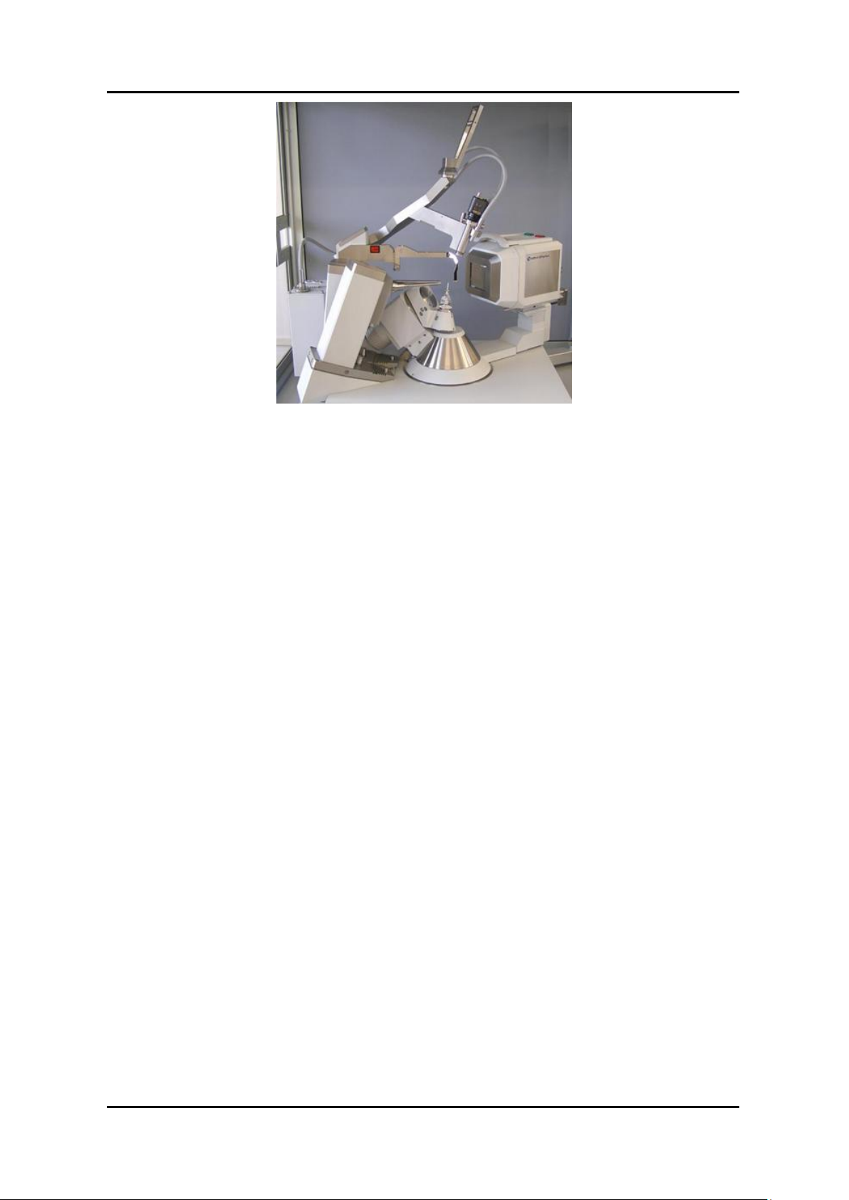
Figure 4.1.2 View of Xcalibur Ultra diffractometer ........................................................................................... 16
Figure 4.1.3 View of Gemini diffractometer ....................................................................................................... 17
Figure 4.1.4 Goniometer phi, kappa, omega and theta axes ........................................................................... 18
Figure 6.1.1 Location of switches ........................................................................................................................ 27
Figure 8.6.1 Goniometer Head Adjustments ...................................................................................................... 39
Figure 8.6.2 Video Microscope Adjustments ..................................................................................................... 39
Figure 8.7.1 View of the access plate and pump out port of the Eos CCD detector .................................. 43
Figure 8.7.2 View of the pump out port of the Atlas/Titan CCD detector.................................................... 43
Figure 12.2.1 Xcalibur / Gemini Suggested Layout .......................................................................................... 55
Figure 12.2.2 System and Component Dimensions .......................................................................................... 56
Xcalibur/Gemini Version 2.4
USER MANUAL Page viii
Page 9
HEALTH AND SAFETY INFORMATION
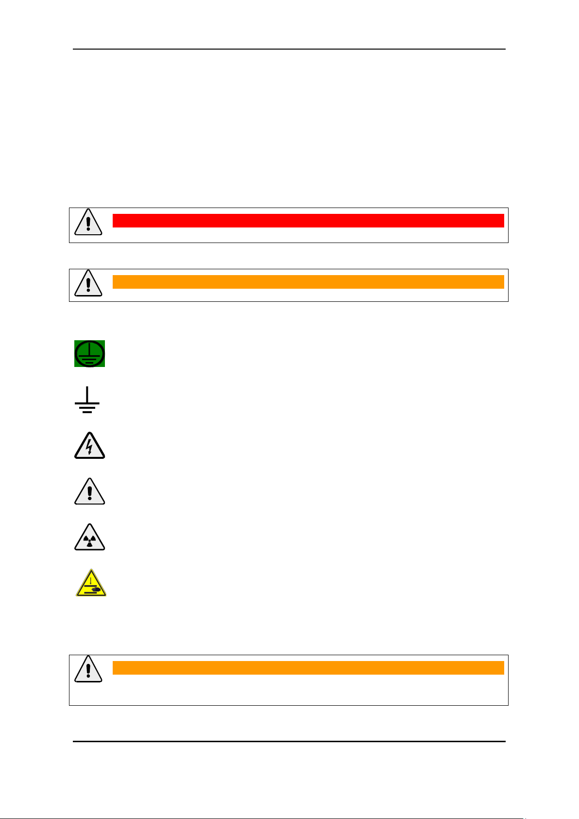
WARNING
Indicates a potential hazard which may result in injury or death
CAUTION
Indicates a potential hazard which may result in damage to equipment
Protective conductor terminal
Earth (ground) terminal
CAUTION
Risk of electric shock
CAUTION
Refer to accompanying documents
WARNING
Radiation Hazard
CAUTION
Risk of finger squeeze between moving parts
CAUTION
Do not take risks. You have a responsibility to ensure the safe condition and safe
operation of equipment.
1. Health and Safety Information
1.1 General
In normal operation the system is designed to operate safely. All users of Xcalibur should be aware of
potential hazards which exist in and around equipment of this type and the ways of avoiding possible
injury and equipment damage which may result from inappropriate ways of working. A description of
such potential hazards and how to avoid them is given in this section.
This manual adopts the following convention:
Warning symbols on the equipment are:
See original manufacturers' manuals for further safety data on third party equipment supplied with the
system. A list of these is given in this manual.
Xcalibur/Gemini Version 2.4
USER MANUAL Page 1
Page 10
HEALTH AND SAFETY INFORMATION
WARNING
The equipment should only be operated and maintained by authorised operators of
the system. An authorised operator is a person who has undergone specialist
radiation training and has been trained in the use of Xcalibur by Agilent
Technologies personnel.
WARNING
All of the electrical equipment supplied as part of the system should be provided
with a protective ground. Do not remove protective grounds as this may give rise
to an electrical safety hazard. It is vitally important that the system is properly
grounded at all times.
Follow local and national electrical regulations and procedures.
Do not defeat interlocks, remove connectors, disconnect equipment, open safety
covers, dismantle or modify equipment unless you are qualified and authorised to
do so and you are fully conversant with its operation and potential hazards, or
have total assurance through your local electrical permit to work system that the
equipment has been made safe.
Ensure that the mains supply is fused at an appropriate rating, or fitted with a
circuit breaker, and that it can be isolated locally via a clearly labelled, clearly
visible and easily accessible isolating switch. Isolate the supply before carrying
out any maintenance work.
Never switch off the CCD detector’s power supply when the KMW200CCD is
operational. To switch off the CCD detector use the KMW200CCD’s front panel
power switch.
1.2 Electrical Safety
In normal use the user is protected from the dangers associated with the voltage, current and power
levels used by the equipment. Only personnel qualified to work with the voltages and currents used by
this equipment should attempt to disconnect, dismantle or modify the equipment.
1.2.1. Potential Electrical Hazards
The following list is not intended as a complete guide to all the electrical hazards on the system, but
serves to illustrate the range of potential hazards that exist:
electric shock
electric burn
fire of electrical origin
electric arcing
1.2.2. Recommended Precautions
Xcalibur/Gemini Version 2.4
USER MANUAL Page 2
Page 11
HEALTH AND SAFETY INFORMATION
WARNING
Do not touch any unshielded wires or connectors while mains power is supplied to
the system.
Do not allow water or any other foreign objects to come into contact with the
equipment’s electrical components.
WARNING
Do not attempt to administer first aid to someone who may have suffered electric
shock until the source of the shock has been isolated.
Mains voltages are present in the system. High voltages are used by the X-ray
tube and power supply. These can cause serious injury or death.
Only personnel qualified to work with high voltages and currents should perform
service or maintenance work on such equipment.
WARNING
Lifting points are provided for safe handling of components and safe handling
practice must be observed to comply with local regulations.
Check that lifting points are used only for the job intended.
The system itself and some components are heavy and require careful handling.
Use safe lifting procedures for heavy items to prevent possible strain injury.
1.2.3. First Aid
A course in first aid to include methods of artificial respiration is recommended for those whose work
involves equipment that may produce a high voltage.
1.3 Mechanical Handling Safety
1.4 Safe Mechanical Practice
In normal use personnel are not required to undertake mechanical work. However, servicing or repair
may necessitate access to any part of the system. Only personnel who have been trained by Agilent
Technologies to carry out service work on this equipment should attempt to dismantle, modify or
repair the equipment.
Water connections should be made and tested in accordance with any local and national safety
regulations.
Xcalibur/Gemini Version 2.4
USER MANUAL Page 3
Page 12
HEALTH AND SAFETY INFORMATION
WARNING
Injury could result if clothing or body parts become caught in moving
mechanisms.
Keep clothing, hands and body parts away from moving mechanisms.
WARNING
Between the moving parts of the goniometer there are a number of places at
which a potential finger squeeze or shearing hazard exists. The warning
triangle shown to the left is visible on the goniometer close to these places.
Keep hands away from the goniometer when parts are moving.
WARNING
1. Systems fitted with the low temperature option use liquid nitrogen and/or
liquid helium as a coolant. Liquid nitrogen and liquid helium are cryogenic
liquids and can cause cold burns. Wear gloves when handling cryogenic
liquids and use eye protection. Refer to the information supplied with the
equipment for more information.
2. During operation both the X-ray tube and the heat sink of the CCD power
supply become hot. In normal use they are located inside a cabinet and hot
parts are not accessible. During maintenance periods, however, it may be
necessary to open the cabinet so that adjustments can be made. Therefore
great care must be taken to avoid touching either the X-ray tube or the heat
sink of the CCD power supply when they are operating and for a period of 20
minutes after operation.
WARNING
This equipment contains an X-ray tube. Ensure that safe working practices
relating to radiation are employed. Follow any local, national or international rules
and guidelines.
Intentional or reckless misuse of the X-ray generator or its safety devices
including safety interlocks and cabinet shielding can result in serious injury or
even death.
1.5 Moving Parts
There are a number of moving parts in the system which are powered by electric motors.
1.6 Extreme Temperatures
1.7 X-ray Radiation
During operation, there is an acceptable level of X-ray radiation as based on the recommendations on
risk published by the International Commission of Radiological Protection (ICRP) and endorsed by the
Health Protection Agency (HPA) in the UK. For use in the UK, the Ionising Radiations‟ Regulations
Xcalibur/Gemini Version 2.4
USER MANUAL Page 4
Page 13
HEALTH AND SAFETY INFORMATION
WARNING
To prevent injury to personnel and possible damage to the equipment, please note
the following guidelines:
1. Only authorised personnel who have received appropriate instruction and are
aware of the laboratory rules that govern the use of this type of system should
operate the system.
2. Never dismount the beam stop when the system is operational.
3. Do not operate the system without the collimator, unless performing the beam
alignment procedure.
4. Use appropriate X-ray detection equipment to perform regular radiation
checks as per any laboratory rules
5. Use only genuine hardware X-ray tubes, X-ray generators, monochromators,
goniometer heads and collimators, as recommended by Agilent Technologies.
Use of other products may compromise the performance of the shielding and
safety system, and may invalidate your warranty.
WARNING
When handling and using X-ray tubes and the CCD detector, particular care
should be taken to avoid injury caused by possible implosion of the vacuum tube.
Wear eye protection.
WARNING
Know the law about high pressure gas cylinders and follow it. High pressure
cylinders are often used to store gases (typically at pressures up to 200 bar). Most
countries have laws about using them.
Chain cylinders to a fixed object or keep them in specially designed trolleys
Only use approved and tested high pressure fittings
1999 should be adhered to. For countries outside the UK the appropriate laws apply such as
registration and inspection.
Customers should be aware of their duty of safety to their employees and visitors.
1.8 Vacuum
1.9 High Pressures
Xcalibur/Gemini Version 2.4
USER MANUAL Page 5
Page 14

HEALTH AND SAFETY INFORMATION
WARNING
If Beryllium is exposed to fire, it may oxidise to highly toxic beryllium oxide
powder. Do not attempt to clear up the remains of any fire, but contact the
relevant local agency stating that there is an incident involving possible beryllium
or beryllium oxide contamination.
1.10 Hazardous or Toxic Materials
Beryllium and beryllium oxide are toxic materials. Follow appropriate handling, shipping, use, storage
and disposal procedures and regulations. Refer to BrushWellman Material Safety Data Sheet No. M10
for further information.
1.11 Maintenance
The manufacturer will not be held responsible for the safety, reliability or performance of the
equipment unless assembly operations, extensions, re-adjustments, modifications and repairs are
carried out only by persons authorised by the manufacturer. Interchangeable parts which are subject
to deterioration during operation must be serviced or interchanged during the intervals given.
Xcalibur/Gemini Version 2.4
USER MANUAL Page 6
Page 15

INTRODUCTION
2. Introduction
2.1 Scope
This manual applies to the Xcalibur system designed and manufactured by Agilent Technologies.
2.2 How To Use This Manual
This manual is aimed at operators and maintenance personnel of the Xcalibur system. Operators of
the system should be computer literate, familiar with X-ray diffraction techniques, have had training in
the use of the Xcalibur system by Agilent Technologies staff, and have had training about radiation
safety.
This manual is intended to provide operators with a practical guide to the system and its operation.
This is intended to familiarise the user with how the system works and provide a better understanding
of the system operation.
All personnel who are likely to operate the system or who are likely to come into contact with any of
the system components should read the HEALTH AND SAFETY INFORMATION section of the manual.
This provides basic information aimed at highlighting the safety hazards associated with the
equipment.
More detailed information and instructions for component parts of the system are given in the third
party manuals supplied with the system, which are listed in this manual. These manuals should also
be read and understood before operating the system.
The purpose of this manual is to:
explain how to operate the equipment
explain how to interface to the equipment
list performance characteristics of the equipment
describe how the equipment operates
assist with simple fault finding and maintenance
2.3 System Overview
The Xcalibur series are single crystal diffractometers that use the property of X-ray diffraction to
determine the crystal structure of materials. They are intended for use with single crystals of chemical
substances (inorganic, organic or organo-metallic), mineralogical and biological samples. The Xcalibur
may also be used in the analysis of powder samples. Intended samples should have a maximum unit
cell dimension of 100 Ångstrom in any direction for small molecule diffractometers and 500 Ångstrom
for macromolecular systems.
The Xcalibur may be used with crystal conditioning devices. Specifically, low and high temperature
attachments and high pressure cells. Some minor modifications may be required by Agilent
Technologies to enable use of these devices.
Xcalibur/Gemini Version 2.4
USER MANUAL Page 7
Page 16

3. Specifications
Ambient temperature during operation
18 – 28 C
Stability of ambient temperature during
operation
1 C
Storage temperature
>10 C
<40 C
Relative humidity
20 - 80 % non – condensing
Location
Clean, dust free environment
>2m from air conditioning or heating units
Floor covering
Conductive or, if carpeted, covered with electrostatic
mats
Floor strength
Able to bear system weight of ~500 kg over an area of
0.64 m2
Total power requirements
230 V 10 % (or 208V for USA) for X-ray generators
and diffractometer
240, 220 or 110V (depending on region) for
temperature attachments and computer monitor.
63 A
All single phase supplies should be connected to the
same phase.
Number of outlets required
1 single-phase outlet (16 A) for diffractometer system
(comprising goniometer, interface, water chillers and
computer etc.)
1 single-phase outlet (32 A) for each X-ray generator
4 single-phase outlets (15 A total) for temperature
attachments and computer monitor.
3.1 Environmental Requirements
SPECIFICATIONS
3.2 Services
3.2.1. Electrical Supply
Xcalibur/Gemini Version 2.4
USER MANUAL Page 8
Page 17

Voltage fluctuation
< 10 % (with line voltage regulator fitted if
necessary)
Location of outlets
On wall behind system (except computer monitor
supply which should be near intended computer table
location)
Protection
Circuit breaker to be fitted to all electrical outlets
3.2.2. Water Cooling
Maximum flow rate
1.8 l/min
Pressure
0.5 – 3 bar gauge
Temperature stability
5 C
Temperature range
5 – 18 C
Composition
Refer to third party manual provided by X-ray tube
manufacturer.
Purity
99.99%
Regulator
low pressure regulator
Minimum pressure
0.5 bar gauge
Flow rate
30 - 40 cm3/min @ ATP
SPECIFICATIONS
3.2.3. Helium Gas Supply For Ultra
Xcalibur/Gemini Version 2.4
USER MANUAL Page 9
Page 18

3.3 Performance Data
Tube
Voltage (kV) setting
Current (mA) setting
Resulting power (kW)
Cu 2.2kW tube
50
40
2.0
Mo 3kW tube
55
40
2.2
Maximum radiation dose due to scattering
at outside surface of the enclosure (door
closed, shutter open)
<0.5 µSv/h (with Mo 3 kW tube operating at 2.2 kW)
Maximum radiation dose due to scattering
(door open, with shutter closed)
<0.5 µSv/h (with Mo 3 kW tube operating at 2.2 kW)
CCD chip
Kodak KAF4320-E
Scintillator material
Gadox
Peltier cooling
-40ºC (two stage cooler)
Temperature stability
± 0.05ºC(micro-processor PID)
Analogue-to-digital resolution
True 18 bit
System noise (so-called read noise)
<10 e- RMS
Dark current
< 0.05 e-/pix.s
Communication
Gigabit Ethernet
Pixel Sampling rate
5.6 MHz
Readout time (complete duty cycle including
chip readout, CDS, analogue-to-digital
conversion, transfer detector-PC, disk storage)
0.22s (4 x 4 binning)
0.46s (2 x 2 binning)
1.59s (1 x 1 binning)
3.3.1. X-ray Tube (Typical Operating Conditions)
SPECIFICATIONS
3.3.2. CCD Detector
3.3.2.1 General
Xcalibur/Gemini Version 2.4
USER MANUAL Page 10
Page 19

3.3.2.2 Eos CCD Detector
Active area
90 – 92 mm diagonal
Overall dimensions (L x W x H)
218 X 178 X 234 MM
Pixel size on scintillator
31 μm
Scintillator material
Gadox
Fibre optic reduction
1.3:1; low distortion reduction taper
Active area
135 mm diagonal
Overall dimensions (L x W x H)
243 X 178 X 234 MM
Weight
16 kg
Pixel size on scintillator
48 μm
Fibre optic reduction
2:1; low distortion reduction taper
Active area
165 mm diagonal
Overall dimensions (L x W x H)
262 X 192 X 241 MM
Weight
20 kg
Pixel size on scintillator
60 μm
Fibre optic reduction
2.5:1; low distortion reduction taper
Communication
Gigabit Ethernet
Drivers
WinXP
Typical host computer
Intel Core 2 Duo class PC
>2 GHz
1.0 Gb RAM
20” colour display
3.3.2.3 Atlas CCD Detector
SPECIFICATIONS
3.3.2.4 Titan CCD Detector
3.3.2.5 PC CCD Interface
Xcalibur/Gemini Version 2.4
USER MANUAL Page 11
Page 20

3.3.2.6. CCD Detector Maximum Theta and Resolution
Mo
Cu
Maximum resolution in 2 theta
155 °
155 °
Maximum resolution in d-value
0.37Å
0.79Å
Mo
Cu
Maximum resolution in 2 theta
133 °
155 °
Maximum resolution in d-value
0.39Å
0.79Å
Mo
Cu
Maximum resolution in 2 theta
155 °
133 °
Maximum resolution in d-value
0.37 Å
0.84 Å
Mo
Cu
Maximum resolution in 2 theta
165 °
163 °
Maximum resolution in d-value
0.36Å
0.78Å
Mo
Cu
Maximum resolution in 2 theta
141 °
163 °
Maximum resolution in d-value
0.38Å
0.78Å
Eos on Xcalibur
Eos on Gemini
SPECIFICATIONS
Eos on Gemini Ultra
Atlas on Xcalibur
Atlas on Gemini
Xcalibur/Gemini Version 2.4
USER MANUAL Page 12
Page 21

Atlas on Gemini Ultra
Mo
Cu
Maximum resolution in 2 theta
165 °
141 °
Maximum resolution in d-value
0.36 Å
0.82 Å
Mo
Cu
Maximum resolution in 2 theta
157 °
156 °
Maximum resolution in d-value
0.37Å
0.79Å
Mo
Cu
Maximum resolution in 2 theta
139 °
156 °
Maximum resolution in d-value
0.38Å
0.79Å
Mo
Cu
Maximum resolution in 2 theta
157 °
138 °
Maximum resolution in d-value
0.37 Å
0.83 Å
CCD detector to sample distance
42 to 150 mm (Eos detector)
52 to 150 mm (Atlas detector)
62 to 150 mm (Titan detector)
Titan on Xcalibur
Titan on Gemini
SPECIFICATIONS
Titan on Gemini Ultra
3.3.2.7. CCD Detector Maximum Distance
Xcalibur/Gemini Version 2.4
USER MANUAL Page 13
Page 22

Type
Four–circle Kappa geometry X-ray goniometer
Sphere of omega, kappa, phi axes
coincidence
10 m
Maximum load Phi axis
2 kg
Reproducibility
0.00125 deg for Omega and Theta
0.0025 deg for Kappa
0.005 deg for Phi
Scanning speed range
0.005 to 3.0 deg/sec
X-ray shutter response time
3 ms
X-ray Generator
System
Power connection
1/N AC 230 V ± 10%
50/60 Hz
1/N AC 230 V ± 10%
50/60 Hz
Maximum mains current at 230V
19 A
4 A
Power outlet fuse
32 A
16A
3.3.3. Four-circle Kappa Geometry X-ray Goniometer
SPECIFICATIONS
3.4 Electrical Data
X-ray Generator and System
Xcalibur/Gemini Version 2.4
USER MANUAL Page 14
Page 23
4. Technical Description
Note:
The numbers on this diagram refer to the numbered list above
1 2 3
4
5
6
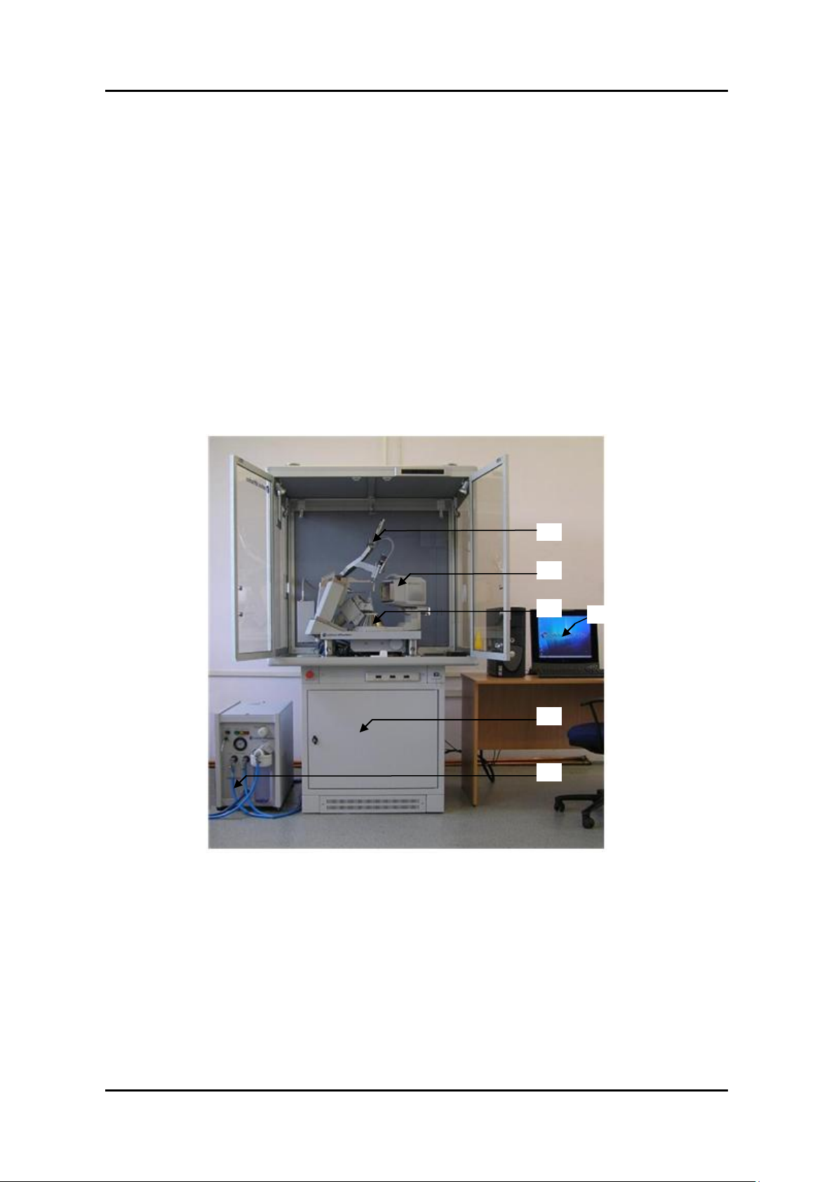
4.1 Overview of Xcalibur/Gemini
The Xcalibur/Gemini system consists of:
1. A kappa geometry, 4-circle diffractometer
2. A CCD area detector
3. An instrument cabinet with electronics rack
4. A stand for optional equipment like high or low temperature attachments
5. System software installed on PC workstation
6. A water chiller for the X-ray tube (type KMW3000C)
TECHNICAL DESCRIPTION
Figure 4.1.1 Components of a typical Xcalibur/Gemini system
The diffractometer and CCD area detector are mounted inside a cabinet. The cabinet experiment area
is mounted on top of the electronics rack. Water chillers for the CCD detector and the X-ray generator
are positioned to the side of the instrument. The PC workstation is located close to the instrument to
allow a clear view of the diffractometer and convenient access to it.
Xcalibur/Gemini Version 2.4
USER MANUAL Page 15
Page 24
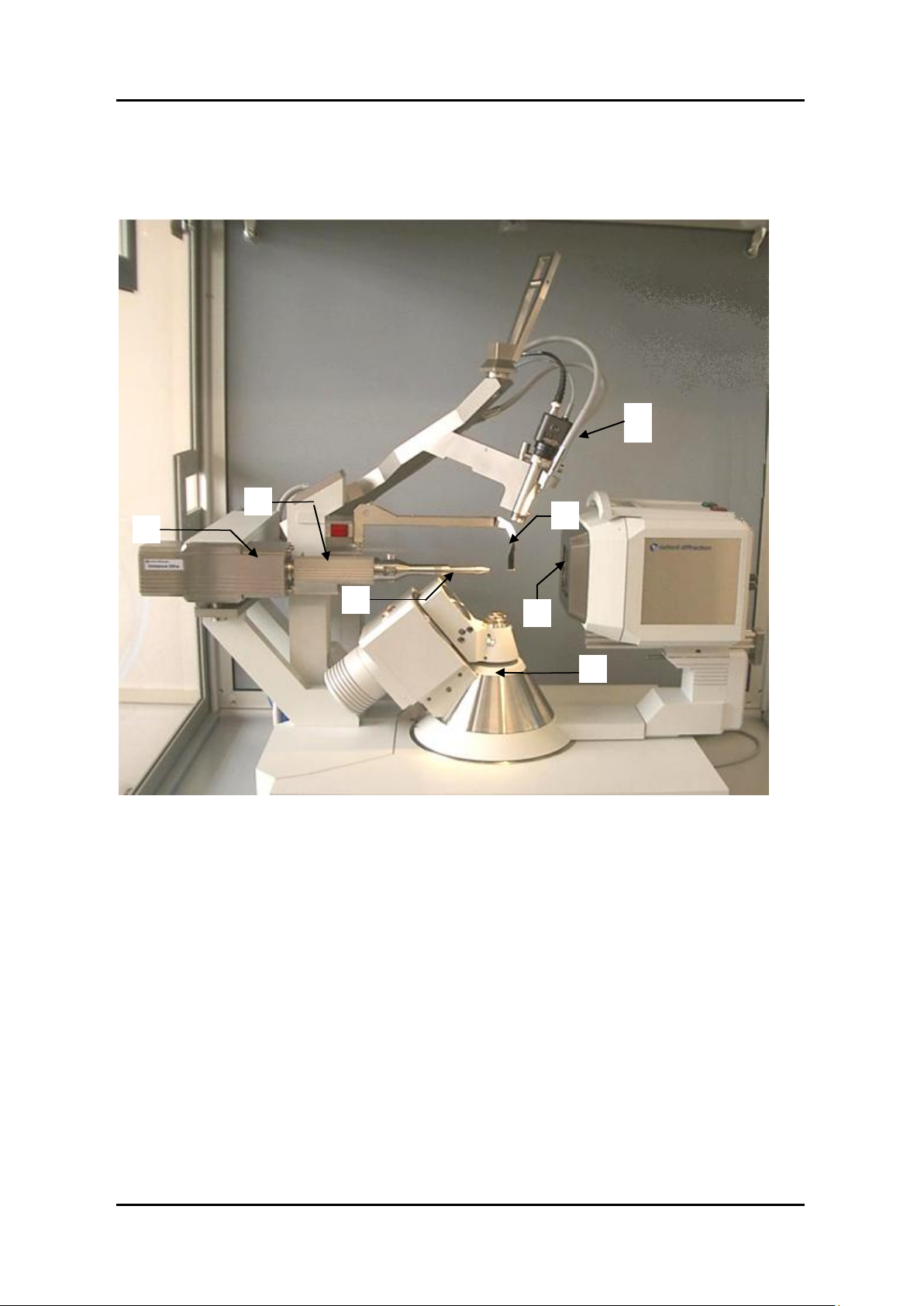
TECHNICAL DESCRIPTION
Key
1. X-ray tube
2. 4-circle Kappa goniometer
3. X-ray Shutter
4. Collimator
5. Beamstop
6. Beryllium Window
7. Video microscope
1 3 4 5 6
2
7
The diffractometer consists of an X-ray tube, a 4-axis Kappa goniometer (omega, kappa, phi and theta
axis) for sample orientation with a detector arm, which has a universal mount capable of supporting
any Agilent Technologies CCD area detector or scintillation point detector. The CCD area detector and
the point detector are used to measure the X-quanta diffracted from the sample.
Figure 4.1.2 View of Xcalibur Ultra diffractometer
The X-rays are generated by a sealed tube, which is mounted on the goniometer and powered by the
high voltage X-ray generator. The X-ray optics consist of a high speed shutter located next to the tube
shield, a monochromator for selecting a specified bandwidth from tube spectrum and a collimator for
limiting beam divergence. The sample can be viewed with the video microscope, which is attached to
the stand doming the instrument. The video image is made available through CrysAlis
the PC monitor just outside the cabinet.
Xcalibur/Gemini Version 2.4
USER MANUAL Page 16
Pro
software on
Page 25
TECHNICAL DESCRIPTION
Figure 4.1.3 View of Gemini diffractometer
The CCD area detector works according to the following principle: The X-rays enter the detector
through a Beryllium window to the vacuum-sealed detector unit. A scintillation screen absorbs the Xrays and emits visible light, which is conducted via a fibre optic reduction taper towards the scientific
grade CCD chip. The CCD signal is digitised to 18-bit resolution by a correlated double sampling circuit
with analog-to-digital converter located in the detector head. The data is then transferred via a gigabit
Ethernet data link to the PC workstation. The control program stores it for further analysis to the hard
disk.
The four-axis goniometer is driven by microprocessor-controlled stepping motors with 12,800
microsteps per revolution.
The sample is aligned using a video microscope. The sample picture is displayed on the control
computer by using the built in frame grabber. The cabinet halogen lighting provides brilliant, high
contrast illumination of the sample at all goniometer positions. Optionally, a fibre optic halogen flood
light system can be ordered to provide additional lighting focussed onto the sample.
The X-ray generator is located in the electronics rack in the instrument cabinet.
The generator power trips out if the X-ray tube overheats and warning lights on the front panel
indicate the operational status of the generator.
The generator is controlled remotely using Crysalis
Pro
software.
Gemini systems contain two generators.
Xcalibur/Gemini Version 2.4
USER MANUAL Page 17
Page 26

TECHNICAL DESCRIPTION
Figure 4.1.4 Goniometer phi, kappa, omega and theta axes
The programs controlling the measurement procedures of the system are WIN32 applications, which
run under Windows XP or Windows 7. The data acquisition and reduction are run concurrently with
the program Crysalis
Pro
.
4.2 KMW200CCD Chiller and KMW3000C Chiller
Information about the Chillers is in separate manuals supplied with this equipment.
4.3 Low Temperature Option
If a cryogenic cooler is to be fitted to the diffractometer system, then the correct adapter must be
used to mount the cooler on the cryo-support stand. Further details can be obtained from Agilent
Technologies.
4.4 Safety Features
In normal operation the X-rays are generated and projected in a totally enclosed cabinet constructed
of lead-doped Perspex called Kyowaglas (equivalent to 0.3mm of lead sheet).
Xcalibur has magnetic switches mounted at the base of the front doors, and at the top of the side and
rear panels of the protective enclosure. During normal operation (i.e. interlocks applied) the X-ray
shutter will not open unless all the cabinet doors are closed. If the doors are then opened whilst the
X-ray shutter is open the X-ray shutter is immediately caused to close.
Access to the interior of the cabinet via the front doors is required when changing samples. When the
doors are opened during sample change and alignment, the X-ray generator remains on for optimum
performance.
Indicator lights mounted on the outside of the enclosure show when the X-ray generator power is on
(orange light) and whether the X-ray shutter is open (red light) or closed (green). If these lights are
Xcalibur/Gemini Version 2.4
USER MANUAL Page 18
Page 27

TECHNICAL DESCRIPTION
defective then the X-ray generator will not operate (in the case of the orange light) and the X-ray
shutter will not open in the case of the red and green shutter lights.
The door of the cabinet should remain locked when the system is unattended to prevent unauthorised
access to the system.
Xcalibur/Gemini Version 2.4
USER MANUAL Page 19
Page 28

HANDLING, INSTALLATION, STORAGE AND TRANSIT INFORMATION
WARNING
The packing crates are heavy and could cause serious injury and damage to the
equipment if not handled correctly. Use suitable lifting equipment and procedures.
Only lift the packing cases from the bottom.
CAUTION
Do not remove the equipment from the packing crates until they have been moved to their
designated installation site. The equipment has been carefully packed to protect the equipment
from damage in transit. Removal of the packing equipment could make the equipment vulnerable to
damage during transit. Do not unpack the equipment until Agilent Technologies personnel are on
site.
5. Handling, Installation, Storage and Transit
Information
5.1 Reception and Handling
5.1.1. Delivery
Carry out the following steps on delivery of the Xcalibur system:
1. When the system arrives, check that there is no visible damage, with the delivery driver present.
If damage has occurred contact the carrier and Agilent Technologies immediately.
2. Check that shock-watch and tilt indicators fitted to the outside of the packing cases have not
been activated. If the indicators have been activated notify Agilent Technologies immediately.
3. Check the number of delivered boxes/crates against the packing list. If any items are missing
contact Agilent Technologies within 3 days.
4. Always lift packing cases from the bottom using suitable lifting equipment (refer to list of
component weights in the following section.
5. Move packing cases into the designated installation site.
6. Contact Agilent Technologies to notify them that the equipment is awaiting installation by a
factory trained service representative.
5.1.2. Unpacking
1. Retain all packing material until installation of the system is completed.
2. Ensure that special tools are stored safely for use during maintenance periods.
Xcalibur/Gemini Version 2.4
USER MANUAL Page 20
Page 29

HANDLING, INSTALLATION, STORAGE AND TRANSIT INFORMATION
Description
NET
Weight
kg
Dimensions
(width x height x depth)
cm
Centre of gravity
Lifting points
Kappa
goniometer
106
43 x 64 x 47
Offset from centre of
unit towards side of
X-ray tube mount
At four corners
(DO NOT lift from
below)
X-ray generator
40
48 x 22 x 69
Centre of unit
From the sides and
below
Enclosure
90
115 x 100 x 100
N/A
N/A
Electronics
rack
60
80 x 85 x 80
Centre of unit
By hand from top
four corners,
otherwise from
below
KMW200CCD
19
60 x 10 x 37
Right hand side of
unit
Underneath at the
four corners
KMW3000C
56
38 x 54 x 96
Centre of unit
At the four corners
and from below
Helijet
10
30 x 25 x 10 (head only)
Centre of component
parts
From below with
transfer tube
removed
Cryojet
15
15 x 35 x 15 (head only)
Centre of component
parts
From below or using
handles whilst
supporting transfer
tube.
Autofill
controller
(ILM210)
5
44 x 10 x 30
Centre of unit
By hand from below
Helijet
controller
(ITC502)
5
44 x 10 x 30
Centre of unit
By hand from below
Helijet gas
flow controller
(GFC1)
12
45 x 26 x 38
Centre of unit
Front panel handles
5.1.3. Mechanical Handling
5.1.3.1 Weights, Dimensions and Lifting Points
Xcalibur/Gemini Version 2.4
USER MANUAL Page 21
Page 30

HANDLING, INSTALLATION, STORAGE AND TRANSIT INFORMATION
Box
(No.)
Item
Length
(cm)
Width
(cm)
Height
(cm)
Weight (kgs)
1
Goniometer
96
61
79
160 2 Protection cabinet
96
116
59
200 3 Electronics rack
91
89
105
170 4 Helijet (option)
100
67
100
110 5 KMW3000C Chiller
105
47
79
100 6 Eos CCD detector
98
85
99
105
Atlas CCD detector
116
94
112
130 Titan CCD detector
116
94
112
145 7 160L LN2 dewar (option)
70
72
155
119 8 21” LCD TFT Monitor
45
28
58
11 9 Cryojet (option)
70
79
189
143
10
X-ray generator
76
60
34
38
11
X-ray generator (for Gemini)
76
60
34
38
5.1.3.2 Boxed Weights, Dimensions and Lifting Points on Delivery
The weights and dimension above are an estimate and should only act as an indication of the lifting
requirements when the system is delivered. All boxes are fitted with the facility to use forks to unload.
There is 15 cm clearance from floor to the base of each box.
It is recommended that a fork lift truck is available to unload the delivery vehicle with a pallet truck to
move the packing cases into the systems final location.
5.2 Installation and Setting to Work
5.2.1. Preparation of Site and Services
5.2.1.1. Environmental Requirements
It is the customer‟s responsibility to ensure that all local building and safety regulations are met.
Ensure that the environmental conditions of the installation site conform to the requirements stated
in the SPECIFICATIONS section of this manual.
USER MANUAL Page 22
Xcalibur/Gemini Version 2.4
Page 31

HANDLING, INSTALLATION, STORAGE AND TRANSIT INFORMATION
5.2.1.2. System Layout
Adequate space is required around the system for servicing. The minimum clearance from the walls
and a suggested system layout are shown in drawing number OD-01-00-15.
When the low temperature option is fitted an extra 100 cm space on the left-hand side of the system
is required.
Unpacked, the largest subassembly will fit through a door aperture of 85 cm. Check the door aperture
to ensure the system can be assembled in its designated area.
5.2.1.3. Electrical Services
A 3-phase 63 A supply, with one or two 32 A outlets (for X-ray generator – one for Xcalibur or two for
Gemini) and one 16 A outlet is required. Additionally four single-phase outlets are required as
described in drawing OD-01-00-015-C.
Use only the power cables supplied.
Do not connect the electrical power supply circuit to any other devices. Limit the electrical noise in
the system by attaching the earth cable exclusively to a system earth terminal with a resistance of
less than 0.5 ohms.
Fit a line voltage regulator if the power supply voltage fluctuates more than ±10%.
Locate the mains outlet on the wall behind the system. The mains outlet should be of the circuit
breaker type. (Outlet and connecting plugs are not supplied). The mains plug should be readily
accessible by the operator when the equipment has been installed.
In areas where the mains power supply is unreliable an „uninterruptible power supply‟ (UPS) is
recommended. The UPS should have specifications of 10 kVA with 3-phase input and single phase
output. For example the following unit from APC will run Xcalibur/Gemini from a 400V 3-phase input
for about 100 minutes:
APC Smart-UPS VT 10kVA 400V w/3 Batt Mod Exp to 4, Start-Up 5X8, Int Maint Bypass, Parallel
Capable + (1)SYBT4 Battery Unit
Xcalibur/Gemini Version 2.4
USER MANUAL Page 23
Page 32

HANDLING, INSTALLATION, STORAGE AND TRANSIT INFORMATION
Description
Voltage
(V)
Frequency
(Hz)
Maximum nominal
mains current
(A)
X-ray generator(s)
1/N AC 230 ±10%
50/60
24
CCD detector
90-130 / 180-260
50/60
2.5
KMW200CCD cooler
100 - 240
50/60
2.5
Goniometer Interface
90-130 / 180-260
50/60
2.5
Cabinet lights, sample illumination
1/N AC 230 ±10%
50/60
2.5
Computer and peripherals
100 - 240
50/60
2.5
Cryojet controller (option)
100 - 240
50/60
2
Autofill controller (option)
100 - 230
50/60
0.6
KMW3000C Cooler
1/N AC 230 ±10%
50/60
1.5
Thermo chiller (option)
208 -240
50/60
5.2.1.4. Water Supply
CCD detector Cooling
The CCD detector is water cooled by the KMW200CCD Cooler. Ten metre long water pipes are
supplied with the system to connect the cooler to an external water supply.
X-ray Tube Cooling
A cooling system is required to dissipate the heat produced by the X-ray tube. A closed circuit cooling
system should be installed to minimise the effects of particles, low pressure and water temperature
fluctuation on the performance of the system from local tap water.
The KMW3000C Chiller is a closed circuit cooling system suitable for this purpose. It is supplied with
two hoses, 10 metres long with 9 mm inner diameter and 15 mm outer diameter. The maximum
distance between the KMW3000C chiller and the system is 10 metres. The distance between the
water supply and the chiller is not limited but the supply must deliver 0.5 – 5 bar gauge pressure with
a minimum 5 litres/min flow and a gravity drain with an elevation that does not exceed 1metre.
The supply should have a wall mounted shut valve.
An additional chiller, such as the ThermoNESLAB, is required when the location of the diffractometer
does not have any running water or lab-cooling system, or if a continuous flow of water cannot be put
down the drain. The KMW3000C is a water-to-water heat exchanger and therefore the heat from the
X-ray tube is removed by the KMW3000C closed water circuit into the main water bath but this heat
load has to be extracted by an additional cold water supply. Refer to the third party ThermoNESLAB
manual for information about this equipment, if supplied.
Xcalibur/Gemini Version 2.4
USER MANUAL Page 24
Page 33

HANDLING, INSTALLATION, STORAGE AND TRANSIT INFORMATION
5.2.1.5. Low Temperature Option
A suitable high vacuum pump, ideally 70 Litres/sec turbo is required to periodically evacuate the
Cryojet head and the heater leg. A KF16 fitting is required for this procedure.
To demonstrate the operation of the Cryojet, 100 litres of liquid nitrogen are required.
The customer should supply a suitable table/rack for both the ILM and the Cryojet controller.
5.2.1.6. CCD Camera Pumping
A high vacuum pump is required to periodically evacuate the CCD camera.
5.2.1.7. Helijet Option
The customer should provide a minimum of 50 litres of liquid helium and a minimum of 1 full helium
gas cylinder of at least 99.99% grade helium gas in order for the operation of the Helijet to be
demonstrated.
5.2.2. Setting to Work
5.2.2.1. Equipment Required
Table for computer (for integration with system)
1 set of Allen keys
Phillips (+) screw drivers (assorted sizes)
Flat headed screw drivers (assorted sizes)
5.2.2.2. Personnel Required for Installation
5 persons for lifting of heavy components
5.2.2.3. Setting up Procedures
Agilent Technologies personnel normally perform installation. The duration of the installation is
typically 4 working days, to include assembly, testing, maintenance and software training.
5.3 Storage
Before installation commences, or when the system is not being used for extended periods, store the
diffractometer in accordance with the environmental conditions for temperature and humidity stated
in the SPECIFICATIONS section of this manual.
Always store Xcalibur in a secure room
Xcalibur/Gemini Version 2.4
USER MANUAL Page 25
Page 34
OPERATION
WARNING
Local rules and regulations may apply to the use of the diffractometer. If these
exist, refer to these local rules before operating the system.
WARNING
Do not operate the diffractometer unless ALL X-ray tubes are fitted. If the X-ray
tube is not present then a high voltage will appear on a bare connector and water
will flow out of the tube shield. When a tube reaches the end of its useful life it
must be left fitted until a new tube is available for exchange.
Control
Type
Location
Effect
Emergency Stop
Red button
Front, left corner of electronics
rack
Shutdown X-ray generator
power and stop goniometer
movement
Remote Control
Key pad
Inside protective enclosure
Control and drive goniometer;
Control must be released from
computer
Cabinet
Illumination
Switch
Front of electronics rack
Illuminate inside of enclosure
Sample
illumination
Switch
Front of electronics rack
Illuminate crystal sample
(optional extra)
Video Microscope
Switch
Front of electronics rack
Switch on / off video
microscope
Flow gauge
(only on systems
fitted with Ultra)
Turn knob
Inside front right of electronics
rack
Control of Helium flow rate
through Ultra optic housing
(should be 30 – 40 cm/min)
6. Operation
Xcalibur is a computer-controlled system. All functions are controlled from the computer terminal
except when control is released from the computer terminal to the remote control unit. Power is
switched on and off via manual switches located on the system.
The KMW200 and KMW3000C chillers must be connected to Xcalibur, before operating the system.
6.1 Controls and Indicators
Control
Xcalibur/Gemini Version 2.4
USER MANUAL Page 26
Page 35
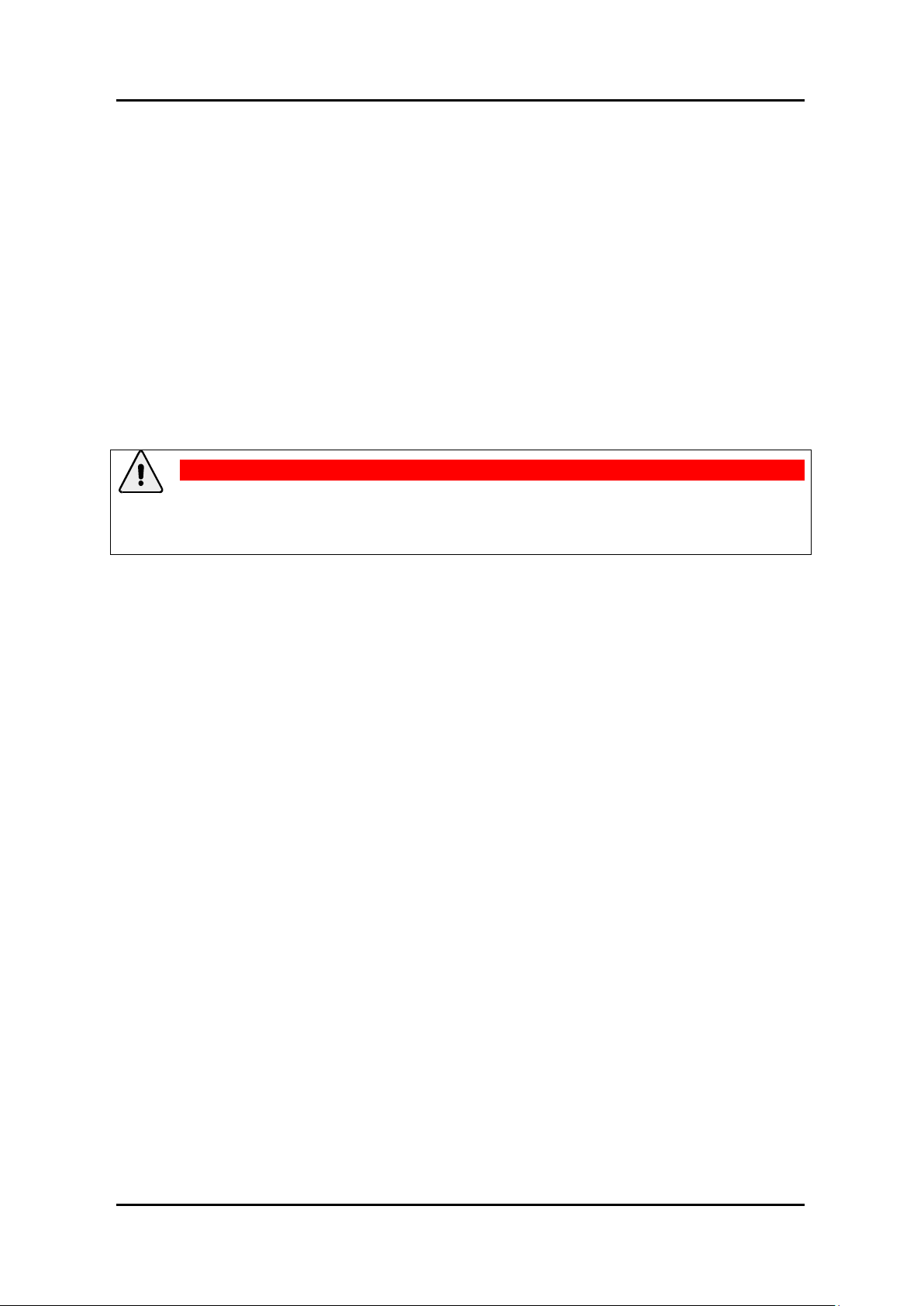
Power
Control
Type
Location
Effect
Diffractometer
goniometer
interface
Red switch
Interface front panel, left;
Inside front door of electronics
rack
Power on / off to goniometer
interface
CCD power supply
Switch
Inside enclosure underneath
power supply box
Power on / off to CCD
detector
Water Cooler (for
CCD)
Red Switch
Cooler front panel, left; Inside
front door of electronics rack
Power on / off to Water
Cooler (also to CCD detector)
Mains power
supply
Switch
Inside left panel, electronics
rack
Power on/off to system
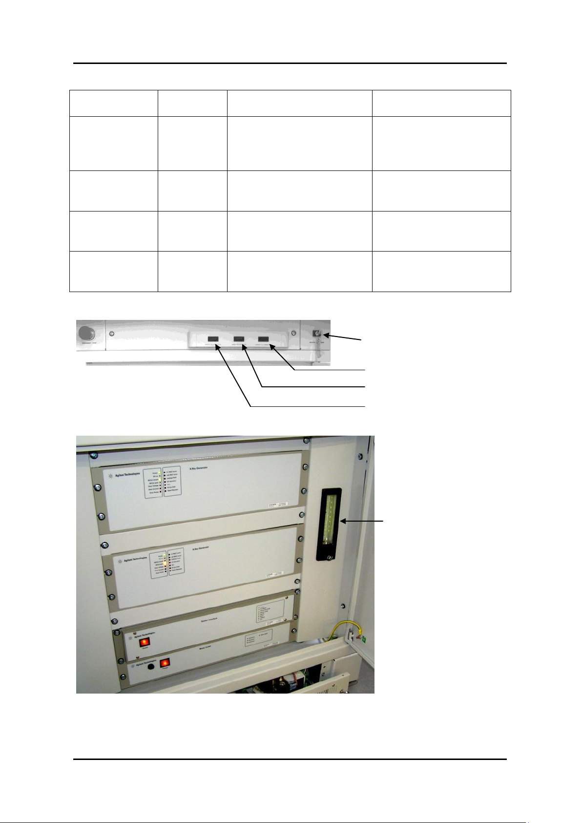
Safety Override Key (for Agilent
service use only)
Cabinet Illumination Switch
Video Microscope Switch
Sample Illumination Switch
(optional)
Flow Gauge (only on systems
fitted with Ultra)
OPERATION
Figure 6.1.1 Location of switches
Xcalibur/Gemini Version 2.4
USER MANUAL Page 27
Page 36

OPERATION
Indicator
Location
Meaning
Orange light
(X-ray Mo)
Outside, top right of the protective enclosure
X-ray Mo generator power is
on
Orange light
(X-ray Cu)
Outside, top right of the protective enclosure
X-ray Cu generator power is
on
Red light (Shutter
open)
Outside, top right of the protective enclosure
X-ray shutter open
Green Light
(Shutter closed)
Outside, top right of the protective enclosure
X-ray shutter closed
Red light (only on
systems fitted
with Ultra)
Back light of flow gauge inside front right of
electronics rack
He gas flow out of range
through gauge. X-ray interlock
is open.
Green light (only
on systems fitted
with Ultra)
Back light of flow gauge inside front right of
electronics rack
He gas flow is within range
through gauge. X-ray interlock
is closed.
Red light (Shutter
open)
Inside top protective cabinet on beamstop
support near X-ray shutter)
X-ray shutter is open
6.2 System Start-Up
Safety devices in the diffractometer protect against damage to the system and the operator during
start up. The following initial switch on procedure should be followed.
1. Plug in all mains power cords to their wall mounted sockets (system, computer monitor).
2. Switch on KMW200CCD chiller using the power switch on the front panel (open the front
door of the electrical rack to access).
3. Wait for the chiller to start-up. The error state lights on the front panel will flash three times
when the chiller is ready. Then check that the detector power supply box is switched on (red
lamp lights on the top).
4. Allow 60-90 minutes for the CCD detector to cool the Peltier and chip to -40ºC.
5. Turn on the interface using the red switch located on the left hand side of the interface front
panel. On the MGC model: ensure 4 green LEDs are illuminated on the right hand side of the
interface panel. (These lights are labeled Power, EXT I/O, Ready and Enable). On the DC08
model: wait 15 seconds for the LEDs to self-test and then ensure 2 green LEDs are
illuminated (these are labeled: Power and Ext Supply)
6. Turn on the computer monitor.
7. Switch on the PC and launch the CrysAlis
initialise. If you have the interface DC08 model then the front panel green LED „Goniometer
Ready‟ should light.
Xcalibur/Gemini Version 2.4
USER MANUAL Page 28
Pro
programme. The goniometer should auto-
Page 37
OPERATION
WARNING
When handling and using X-ray tubes particular care should be taken to avoid
injury caused by exposure to the X-rays, exposure to high voltages, possible
implosion of the vacuum tube and contact with Beryllium and Beryllium oxide.
8. Switch on the KMW3000C chiller using the key provided. (Ensure that the external circuit
water cooling is also turned on).
9. Turn on the X-ray generator (switch on the generator back panel).
10. To generate X-rays open the X-ray device server in the Crysalis
28 kV, 1 mA then press OK. The generator should now ramp up to these settings. If the X-ray
tube has not been running for >1 hour follow the warm-up procedure suggested in the
manufacturers manual.
11. After closing all protection cabinet panels the system will enable the X-ray shutter interlock
(to allow it to be opened after a command from the software). If you have the interface DC08
model then the front panel green LED „Shutter Enable‟ should light.
Pro
GUI. Click on start and enter
6.3 X-ray Tube Warm-up Procedure
If the X-ray tube is stored for a lengthy period, the vacuum may become impaired. We recommend
carrying out the following warm-up procedure for new tubes and tubes that have not been used for
more than 100 hours.
Use Crysalis
the tube manufacturer‟s manual.
If, after completion of this procedure, a flashover occurs in the next 30 minutes, repeat the whole
procedure.
Pro
X-ray device server software control to carry out the burn in procedure as detailed in
6.4 System Standby and Normal Shutdown Procedure
Depending on the period of diffractometer inactivity, follow one of the 3 procedures below.
6.4.1 Shutdown Procedure (Diffractometer not expected to be used for 2-3 days)0.
1. Ramp down the X-ray generator to 10 mA, 30 kV (improves lifetime of the X-ray tube).
2. Park the goniometer in its home position simply by exiting the Crysalis
3. Turn off the video microscope using the front panel mounted switch.
4. Turn off the cabinet & sample illumination using the front panel mounted switches.
5. Warm up/turn off sample cooling device (following manufacturers guidelines) – where
applicable.
6. Logoff the computer and shut down.
Pro
program.
7. Turn off the computer Monitor („O‟ on the screen).
Xcalibur/Gemini Version 2.4
USER MANUAL Page 29
Page 38

OPERATION
WARNING
The emergency stop button will only shut down high voltage from the X-ray
generator. Other equipment on the system will still be powered on.
6.4.2 Shutdown Procedure (Diffractometer not expected to be used for 1 week or more)0.
1. Turn off X-ray generator using the X-ray device server in the Crysalis
flow for 15 minutes to cool tube.
2. After 15 minutes turn off the KMW3000C X-ray tube chiller using the key provided. You may
wish to turn off the external water supplying circuit, although this is not necessary since a
thermostatic valve will cease flow when the bath reaches a pre-determined temperature.
3. Park the goniometer in its home position simply by exiting the Crysalis
4. Turn off the video microscope using the front panel mounted switch.
5. Turn off the cabinet & sample illumination using the front panel mounted switches.
6. Warm up/turn off sample cooling device (following manufacturers guidelines) – where
applicable.
7. Logoff the computer and shut down.
8. Turn off the computer Monitor („O‟ on the screen).
9. Turn off the diffractometer interface (red illuminated switch located on the left side of the
front face).
Pro
GUI). Allow water to
Pro
program.
6.5 Emergency Shutdown
The emergency shutdown procedure should be used:
If there is a fire or any other emergency requiring the evacuation of personnel from the area
AND
The procedure can be performed without endangering any persons‟ safety.
6.5.1. Emergency Shutdown Procedure
0.
1. Press the red emergency stop button located on the front left of the system.
2. Switch off all power at the mains electrical supply.
3. Turn off mains water supply.
0.
Xcalibur/Gemini Version 2.4
USER MANUAL Page 30
Page 39

MAINTENANCE SCHEDULES
CAUTION
1. Maintenance tasks must only be carried out by authorised operators who have
undergone specialist radiation training. Refer to local rules for further details.
2. Failure to perform scheduled maintenance tasks properly and at the correct
intervals can affect the safety and performance of this system.
3. Before performing any maintenance task ensure that you have read and
understood the HEALTH AND SAFETY INFORMATION at the beginning of this
manual and any local rules governing the use of the diffractometer system
Action
Personnel
Estimated task
duration
Estimated
elapsed time
1. Check door and cabinet window
safety interlocks
Authorised Operator
2 minutes
2 minutes
Action
Personnel
Estimated task
duration
Estimated
elapsed time
1. Check Emergency Stop
Authorised Operator
10 minutes
10 minutes
2. Check X-ray radiation levels
Authorised Operator
20 minutes
20 minutes
7. Maintenance Schedules
7.1 Introduction
Various maintenance tasks must be performed to ensure that the diffractometer system continues to
operate safely and reliably. These tasks are detailed in the maintenance schedules given below.
Planned maintenance that can be performed by the user is limited to replacing consumable items,
alignment procedures, pump-down procedures, and checking radiation levels and safety features. The
user‟s authorised service representative should carry out other tasks. If in any doubt about the
performance of the diffractometer, contact Agilent Technologies.
7.2 Weekly Maintenance Schedule
Tools and Materials:
None
7.3 Monthly Maintenance Schedule
Tools and Materials:
Radiation meter
Xcalibur/Gemini Version 2.4
USER MANUAL Page 31
Page 40

MAINTENANCE SCHEDULES
Action
Personnel
Estimated task
duration
Estimated elapsed
time
1. Refining machine parameter file
Authorised Operator
4 – 5 hours
4 – 5 hours
2. Check alignment of video
microscope and cryogenic
cooling device (if fitted)
Authorised Operator
1 hour
1 hour
Action
Personnel
Estimated task
duration
Estimated elapsed
time
1. Refine machine parameter file
Authorised Operator
4 - 5 hours
4 – 5 hours
2. CCD detector – pump out
vacuum
Authorised Operator
30 minutes
3- 6 hours
(depending on
detector)
7.4 Six Monthly Maintenance Schedule
This maintenance schedule should also be completed after adjustment of the X-ray beam, collimator
and CCD detector position.
Tools:
Ylid test crystal - (C11H10SO2)
7.5 Yearly Maintenance Schedule
Tools and Materials:
Ylid test crystal - (C11H10SO2)
Special „T‟ tool
Phillips screw driver
Rotary vacuum pump capable of obtaining a pressure of <0.04 mbar
Vacuum tubing and adaptor
7.6 10,000 Hours Maintenance Schedule
Tools and Materials:
Set of Allen keys
Set of flat-headed screwdrivers
Water receptacle (e.g. Bucket)
Special tools –special tool 1 and special tool 2 (see section 8 for identification)
Xcalibur/Gemini Version 2.4
USER MANUAL Page 32
Page 41

MAINTENANCE SCHEDULES
Action
Personnel
Estimated task
duration
Estimated elapsed
time
1. Changing the X-ray tube
Authorised Operator
30 minutes
30 minutes
2. Alignment of X-ray optics
Authorised Operator
2 hours
2 hours
Xcalibur/Gemini Version 2.4
USER MANUAL Page 33
Page 42

MAINTENANCE INSTRUCTIONS
WARNING
1. Read and understand the Health and Safety Information section of this manual
before performing any maintenance procedures.
2. Follow any local, national or international rules and guidelines that apply to this
equipment when performing maintenance tasks.
3. Maintenance tasks must only be performed by authorised operators of the
diffactometer.
Task Time:
4 – 5 hours
When:
After adjustment of beam, collimator, CCD detector position etc. Otherwise twice a
year.
Tools:
Ylid test crystal - (C11H10SO2)
8. Maintenance Instructions
Some procedures in this section require that commands are entered in the command line. To open the
command line:
1. Launch Crysalis
2. Click on the “command line“ icon on the left hand side tool bar. 0.
Pro
8.1 Refining the Machine Parameter File
Procedure:
See section „Refining of Machine Parameter File‟, located in the CrysAlis
Pro
software manual.
Xcalibur/Gemini Version 2.4
USER MANUAL Page 34
Page 43

MAINTENANCE INSTRUCTIONS
Task Time:
30 mins
When:
Sealed source X-ray tubes have a limited useful lifetime. Operation of a 2.2 kW
tube at typical output of 1.5 kW will normally provide 10,000 hours of use (actual
values may vary, see third party manual).
Note: X-ray tubes also have a limited shelf life.
Who:
Agilent authorised operator, trained on radiation safety
Tools:
Set of Allen keys
Set of flat-headed screwdrivers
Water receptacle (e.g. Bucket)
WARNING
Do not touch the Beryllium windows in the X-ray tube. Beryllium is a potentially
toxic material.
CAUTION
The customer may change the X-ray tube of Enhance Ultra but the focussing optic inside
this X-ray source must be precisely aligned to each new X-ray tube and this may only be
performed by a trained Agilent Technologies service engineer. Missing this alignment
could result in worse performance of this X-ray source.
CAUTION
Use only ceramic X-ray tubes not glass X-ray tubes
Remove all packaging material and red plugs from water openings before fitting
X-ray tube must be inserted in the correct orientation with the Agilent Technologies logo
upside down.
CAUTION
Have a receptacle ready to receive water from the pipes and X-ray tube shield.
8.2 Changing the X-ray Tube of Ultra (Horizontal X-ray tubes)
Procedure
1. Switch off the power to the X-ray tube to be changed.
2. Turn off the KMW3000C chiller to stop water circulating.
3. Leave for at least 20 minutes to ensure that the X-ray tube is not hot (test temperature before
proceeding).
Xcalibur/Gemini Version 2.4
USER MANUAL Page 35
Page 44

MAINTENANCE INSTRUCTIONS
CAUTION
Failure to fit these o-rings will result in water leakage which could damage both
the X-ray tube and the instrument.
WARNING
Ensure that the X-ray tube is correctly mounted. Incorrect mounting may result in
exposure of personnel to X-ray radiation.
4. Disconnect the top water pipe from back of Ultra X-ray tube shield (This is attached with a quick
release connector).
5. Remove the Ultra front face panel. To do this locate the metal block on the left side of the X-ray
tube housing, which is behind the front face panel, find the single screw at the rear of this block
which is holding the front face panel and use a 5mm Allen key to completely undo the screw. Lift
off the front face panel.
6. Unscrew the temperature sensor from the front plate (metal base, with label) of the X-ray tube.
7. Release the two screws holding the X-ray tube in place and withdraw the X-ray tube from the X-
ray shield. Do this by holding the front plate (metal base, with label) and pulling towards the front
of the Ultra. Ensure that the X-ray tube is held level and withdraw parallel to the X-ray shield.
8. For disposal of used X-ray tubes see the DISPOSAL chapter of this manual.
9. Make sure the two o-rings remain in their grooves at the front of the tube shield.
10. Replace the X-ray tube with an identical specification Cu X-ray tube. Holding by its metal base,
remove the new X-ray tube from its protective box
11. From the front of the ULTRA insert the X-ray tube into the tube shield, in the same orientation as
the previous one, and secure with two screws.
12. Re-mount the thermocouple to the base of the X-ray tube and re-mount the ULTRA front face
panel. Secure in place using a 5mm Allen key and the single screw described above.
13. Re-connect the water supply to the back of the ULTRA X-ray tube shield.
14. Switch on power to the generator and KMW3000C chiller unit.
Xcalibur/Gemini Version 2.4
USER MANUAL Page 36
Page 45

MAINTENANCE INSTRUCTIONS
Task Time:
30 minutes
When:
Sealed source X-ray tubes have a limited useful lifetime. Operation of a 3 kW Mo
tube at typical output of 2 kW, and a 2.2kW Cu tube at 1.5 kW, will normally
provide 10,000 hours of use (actual values may vary, see third party manual).
Note: X-ray tubes also have a limited shelf life.
Who:
Agilent authorised operator, trained on radiation safety
Tools:
Set of Allen keys
Set of flat-headed screwdrivers
Water receptacle (e.g. Bucket)
WARNING
Do not touch the Beryllium windows in the X-ray tube. Beryllium is a potentially
toxic material.
CAUTION
Use only ceramic X-ray tubes not glass X-ray tubes
Remove all packaging material and red plugs from water openings before fitting
X-ray tube must be inserted in the correct orientation with the Agilent Technologies logo
upside down.
8.3 Changing the X-ray Tube of Enhance (Vertical X-ray Tubes)
Procedure
1. Switch off the power to the X-ray tube to be changed.
2. Turn off the KMW3000C chiller to stop water circulating.
3. Leave for at least 20 minutes to ensure that the X-ray tube is not hot (test temperature before
proceeding).
4. Switch off and remove any cryogenic device mounted on the diffractometer.
5. Remove the plate for mounting cryogenic devices (3x M8 screws to be removed from top of
attachments tower).
6. Unscrew (one screw at the front and the back) the end cap from the top of the Enhance and
remove (this may also need the loosening of the conical cover at the base end of the
collimator for the Cu source) and lay to one side along with the integrally mounted thermal
sensor.
7. Unscrew and slide out the X-ray tube in an upwards direction. A little water inside the end of
the X-ray tube plate will drip out and should be cleaned up, but otherwise all water in the
system will be retained inside the pipes.
8. Make sure the two o-rings remain in their grooves at the top of the tube shield.
Xcalibur/Gemini Version 2.4
USER MANUAL Page 37
Page 46

MAINTENANCE INSTRUCTIONS
CAUTION
Failure to fit these o-rings will result in water leakage which could damage both
the X-ray tube and the instrument.
Task Time:
<1 min
When:
Different sizes of collimator may be necessary for different experiments Three
standard collimators of sizes 0.5, 0.8 and 1.0 mm are provided with the
diffractometer system. A 0.3 mm standard length collimator and a short 0.3 and 0.5
mm collimator (for use in high pressure experiments) are available by special
order. Different lengths of collimator are used for Mo and Cu sources, the longer
collimators are for the Mo source.
Tools:
None
WARNING
Ensure that the collimator is correctly mounted. Incorrect mounting may result in
exposure of personnel to X-ray radiation.
WARNING
Ensure that the X-ray tube is correctly mounted. Incorrect mounting may result in
exposure of personnel to X-ray radiation.
9. Fitting the new tube is the reverse procedure (maintaining the same orientation of the tube).
10. For disposal of used X-ray tubes see the DISPOSAL chapter of this manual.
11. Holding by its metal base, remove the new X-ray tube from its protective box.
12. Slide the X-ray tube into position on the diffractometer and secure with two screws.
13. Fit the end cap (with integral temperature sensor) onto the top of Enhance and secure using
the two fixing screws.
14. Re-fit the plate for mounting cryogenic devices.
15. Re-fit any cryogenic device.
16. Switch on KMW3000C water chiller.
8.4 Changing the Collimator of Enhance
Procedure
1. Ensure that the X-ray shutter is closed and all interlocks are in place.
2. No sample should be mounted on the goniometer.
3. Pull out the collimator from its housing, pulling from the right hand side. Be careful not to touch
the beamstop or CCD detector.
4. Select the required size of collimator and push into position on the diffractometer such that it is
flush to the housing surface. The collimator should be inserted such that the flat edge with the
collimator size label is uppermost.0.
Xcalibur/Gemini Version 2.4
USER MANUAL Page 38
Page 47

MAINTENANCE INSTRUCTIONS
Task Time:
< 30 minutes
When:
When it becomes impossible to centre a sample correctly on the video microscope
image.
Tools:
Pre-mounted 0.3 mm steel ball mounted on a goniometer head.
Figure 8.6.1 Goniometer Head Adjustments
Figure 8.6.2 Video Microscope Adjustments
Left / right Adjusters
Height Adjuster
Equivalent to Height Adjustment
Left / right Adjustment
Focus
8.5 Aligning the X-ray Collimator of Enhance
The X-ray collimator is factory aligned via the collimator housing. This means that re-alignment is not
needed when changing between the collimators supplied by Agilent Technologies.
If collimator re-alignment is required please contact Agilent Technologies for assistance.
8.6 Aligning the Video Microscope
When first assembled the Goniometer sample centre and the video microscope focal point should be
close to each other, however the video image only displays a field of view approximately 1.2mm x
0.8mm and its depth of field is similarly limited. Adjustments need to be made so that the sample
centre and microscope focal point coincide exactly. Both the Goniometer head and the video
microscope have adjustments to move their centres in three planes. Agilent Technologies supply a
pre-mounted 0.3mm steel ball to aid this procedure.
The three adjustments for the microscope can be seen in the figure above (Video Microscope
Adjustments).
Xcalibur/Gemini Version 2.4
USER MANUAL Page 39
Page 48

MAINTENANCE INSTRUCTIONS
NOTES
An indication that the video microscope is not properly centred is if the sample cannot be
centred to the middle of the video image, then small adjustments of the microscope may
be needed during the sample centring process. The focus may also need adjusting
occasionally if the Crystal size varies widely from one experiment to another.
For a correctly centred sample, and video microscope, the variation in position of the
sample (Sphere of Confusion) as it rotates to any of the positions on the remote control
(except home) should be one small division on the image (10μm). In the unlikely event
that correct centring cannot be achieved contact Agilent Technologies for advice.
To centre the video microscope and therefore the steel ball on the centre of the video image use the
following procedure:
Procedure
1. Within the CrysAlis
goniometer to the remote control pad.
2. Mount the 0.3mm steel ball plus goniomenter head onto the goniometer.
3. Press the „Lower‟ then ‟0‟ keys and wait for the goniometer to stop moving.
4. Adjust the goniometer head such that the steel ball is visible on the video image.
5. Press „180‟ and watch the steel ball as it is rotated, it will probably move off image. Use the
adjustments on both the Head and Microscope equally to move the ball back to the centre, press
„0‟. The ball should end up close to the centre of the image, adjust again to make it central, repeat
as necessary until the movement of the ball is minimised.
6. Press „90‟ and move the ball to the centre using the head only.
7. Press „270‟ and watch the ball as it rotates. If the microscope is correctly centred left to right it
will be possible to centre the ball using only the Head adjustments, if not small adjustments of
the microscope may be required, repeat until the ball appears to spin on the spot for all four angle
positions.
8. Press „0‟, then „Upper‟, watching the ball as it moves. Use the height adjustments on both the
Head and the microscope equally to re-centre the ball, press „Lower‟ and repeat step 8 until there
is no movement of the ball as the goniometer moves between the two positions.
Pro
software, press „F12‟ on the computer keyboard to release control of the
9. Repeat steps 5 to 7 at the „Upper‟ position.
10. Adjust the focus on the microscope to bring the ball into sharp focus. The video microscope is
now aligned. The video microscope should not need to be adjusted again, unless it is knocked or
extra weight is added to, or removed from the support arm, for example, a low temperature device
is added or removed.
11. When fully centred in the Upper and Lower positions the goniometer should be sent back to
„Home‟ once this is complete the ball (or Crystal) will appear to be displaced towards the left of
the video image. This is an optical illusion caused by the angle of the microscope with respect to
the Crystal at „Home‟ and can be ignored. .
Xcalibur/Gemini Version 2.4
USER MANUAL Page 40
Page 49

MAINTENANCE INSTRUCTIONS
Task Time:
2 minutes
When:
Once a week
Tools:
None
Task Time:
10 minutes
When:
Once a month
Tools:
None
8.7 Checking the Door Safety Interlocks
Procedure
1. With the diffractometer in normal operation and at normal X-ray generator settings, open the
shutter using the shutter open button in the Service Power Tool of the CrysAlis
2. Open the front doors of the enclosure cabinet. The X-ray shutter should immediately close.
3. Close the enclosure doors.
4. Repeat step 1 and open the side panels of the cabinet. The X-ray shutter should immediately close.
5. Close the side panels.
6. Repeat step 1 and open the back panels of the cabinet. X-ray shutter should immediately close.
7. Close the back panels.
Pro
software.
8. Using the weekly maintenance sheet (see appendix). Record the date, persons testing and sign off
the outcome.
8.8 Checking the Emergency stop
Procedure
1. With the diffractometer running at minimum settings (for example 28 kV, 1 mA), press the red
Emergency Stop button.
2. The X-ray generator should switch off immediately, release the emergency stop button by twisting
anti-clockwise, restart the X-ray generator. Return the generator / X-ray tube to required settings.
3. Switch off the interface, wait 5 seconds, restart the interface and then in the Service Power Tool
of CrysAlis
Pro
click on the radio button gon reinit and click Start.
4. Using the monthly maintenance schedule (see appendix) record details of the test, stipulating the
date, person testing, outcome and signature. .
Xcalibur/Gemini Version 2.4
USER MANUAL Page 41
Page 50

MAINTENANCE INSTRUCTIONS
Task Time:
20 minutes
When:
Once a month
Tools:
Appropriate Radiation meter for X-ray energy levels (Mo14 keV, Cu 8 keV)
Task Time:
3 hours
When:
Once a year
Tools:
Special „T‟ tool (carried by Agilent Technologies service engineer)
1 set of Allen keys
Rotary vacuum pump capable of obtaining a pressure of 1x10⁻¹ mbar
Vacuum tubing and adaptor
8.9 Checking the X-ray Radiation Levels
Procedure
1. With the X-ray generator on (at normal operational settings) and the shutter closed, use the
radiation meter to sweep the area inside the cabinet and around the X-ray tube housing, fast
shutter and collimator for any radiation leak.
2. Close the protective enclosure doors and open the X-ray shutter. In the Service Power Tool of
CrysAlis
3. Sweep the outside of the enclosure using the radiation meter, paying particular attention to the
plane of the X-ray tube, the area of the secondary beam stop (mounted on the right hand side
enclosure window) and the door seals.
Pro
click on Shutter Open.
4. Close the X-ray shutter by clicking on the Shutter Close button in the Service Power Tool.
5. Using the monthly maintenance schedule log, record details of the test, stipulating the date,
person testing, outcome and signature.
8.10 CCD Detector – Pumping Out Vacuum
Procedure 0.
1. Switch off the cooling water for the CCD detector at the cooler/ chiller unit.
2. Allow one hour for the detector to warm to room temperature.
3. For the Eos detector unscrew front four corners of the collision sensor of the CCD detector. This
is spring loaded so be ready to catch it as you release the screws. Remove the front of the CCD
detector.
Xcalibur/Gemini Version 2.4
USER MANUAL Page 42
Page 51

MAINTENANCE INSTRUCTIONS
Pump out port (with „T‟ tool
attached)
Pump out port (with cover
unscrewed)
CAUTION
Only use new, clean tubing. Apply vacuum before removing the CCD detector vacuum seal
to prevent oil etc. diffusing into the detector and causing damage.
CAUTION
Do not turn off the vacuum pump until the CCD detector has been sealed using the
relevant stopper.
Figure 8.7.1 View of the access plate and pump out port of the Eos CCD detector
4. For the Atlas or Titan detector unscrew the cap from the pump out port
Figure 8.7.2 View of the pump out port of the Atlas/Titan CCD detector
5. Screw the „T‟ tool into place on the pump out port.
6. Attach vacuum pump to the side arm of „T‟ tool using a suitable adaptor and vacuum tubing.
7. Switch on vacuum pump and evacuate tubing / pumping line to 1x10
-1
bar pressure.
8. Depress „T‟ tool plunger and screw into place. This screws into the o-ring sealed metal stopper
that secures the detector vacuum.
9. Slowly withdraw plunger to remove stopper. Secure plunger in extended position.
10. Leave under vacuum for 20 minutes.
11. Slowly depress „T‟ tool plunger to replace stopper and unscrew plunger
Xcalibur/Gemini Version 2.4
USER MANUAL Page 43
Page 52

MAINTENANCE INSTRUCTIONS
12. Switch off vacuum pump and disconnect pipes.
13. Unscrew „T‟ tool and replace the cap on the port of Atlas or Titan. For Eos replace the front
access plate of CCD detector, leaving 1mm gap equally all around the edge of the collision sensor.
14. Switch on the cooling water for the CCD detector at the cooler/chiller unit and monitor the cool
down using the CCD device server until the set temperature is obtained.
Xcalibur/Gemini Version 2.4
USER MANUAL Page 44
Page 53

9. Trouble Shooting
Symptom
Fault
Solution
X-ray shutter will not
open (resulting in blank
images in the software)
1. Shutter is not enabled
If you have interface model DC08:
open front door of electrical rack
and look for Shutter Enable green
LED illuminated on front panel. If it
is not then proceed with the checks
below.
2. Protective cabinet doors are not
closed properly
Close doors properly. If the interface
is model DC08 then the front panel
will show the green LED „Shutter
Enable‟. Otherwise if the safety
circuit is closed a green lamp is
illuminated within the control
electronics. Access is via the left
side panel of the electronics
cabinet.
3. Shutter-open and /or shutter
closed lights defective
Check light connections and LED
light display.
To check if LED arrays are working;
turn off the interface, wait 5
seconds and turn back on the
interface. For a short period all
shutter indicators should be
illuminated (i.e. open/closed on
the exterior of the cabinet and the
Shutter Open (red) lamp inside the
cabinet on the beamstop
mounting)
4. Protective cabinet doors were
opened whilst the shutter was
open and safety circuit was
activated
In CrysAlis
Pro
re-start experiment.
5. X-ray generator is turned off
Turn on X-ray generator and start
high voltage.
6. Shutter signal cable
Ensure that the shutter cable
(Fischer connection) is secured to
the optics/shutter housing.
TROUBLE SHOOTING
Xcalibur/Gemini Version 2.4
USER MANUAL Page 45
Page 54

TROUBLE SHOOTING
Symptom
Fault
Solution
7. He flow is out of normal range
(ULTRA)
Adjust He flow rate to normal range
so that lamp behind flow gauge
shows green colour, not red.
8. Beam stop is in the „up‟ position
(ULTRA)
Move beam stop to the „down‟
position.
9. Emergency stop has been
pressed.
Ensure emergency stop has not
been pressed (generator will also
not function). If yes, twist to
release and turn off/on the
interface.
Generator will not
generate X-rays
1. No power reaching the generator
1. Ensure fuse or circuit breaker of
mains supply is OK.
2. Ensure switch on the unit (rear
panel) is in the correct (1)
position.
2. Computer RS232 communication
is not connected
Check COM cable from generator is
connected at the rear of the
computer. Check COM port
number has been detected by
CrysAlis
Pro
.
3. Emergency stop has been pressed
and not released.
1. Twist emergency stop button
clockwise to release.
2. Restart high voltage on generator.
3. Switch off system interface at the
front panel, wait 3 s and then
restart. Type gon reinit on
Crysalis
Pro
command line
4. If Mo X-rays are required then
change over radiation type
(Gemini models only) using
software button.
Xcalibur/Gemini Version 2.4
USER MANUAL Page 46
Page 55

TROUBLE SHOOTING
Symptom
Fault
Solution
4. No cooling water is flowing
1. Check KMW3000C water cooler is
switched on.
2. Check water cooler has no error
state
3. Check all necessary water valves
are open
4. Check external cooling water
supply is flowing and has an
acceptable temperature.
5. X-ray tube temperature is too high
There is a temperature switch on
the top of the X-ray tube. If it is
hot then wait for it to cool down.
Investigate the reason for
overheating of the X-ray tube
before proceeding.
6. X-ray lamp on cabinet is defective
Check light connections and LED
light display.
7. Additional X-ray lamp is defective
Some laboratory installations have
an additional X-ray lamp in the
interlock circuit. This might be
wall-mounted near to the system
or outside the laboratory. Check
the lamp connections and the
replace the bulb with the same
type, if necessary.
Problem reading kV
and mA from generator
1. RS232 communication cable not
connected properly
Check the RS232 cable is connected
to back of PC (serial COM port) and
to back of the generator
2. Check PC serial port is working
CrysAlis
Pro
should search through all
available serial ports
Xcalibur/Gemini Version 2.4
USER MANUAL Page 47
Page 56

TROUBLE SHOOTING
Symptom
Fault
Solution
Software cannot
control goniometer
No communication with interface
1. Check interface is switched
on.
2. For interface model MGC:
Check RS232 serial cable is
connected between rear of
PC and the interface. For
interface model DC08:
Check Ethernet cable is
connected between PC and
system and to rear panel of
interface.
3. For interface model MGC:
check emergency stop on
the front of the interface
has not been pressed. If
yes, twist it to release, turn
off power on front panel,
wait 5s and then restart.
Goniometer axis will not move
1. Check the goniometer is
connected to the interface
with two cables. (Always
turn off the interface before
plugging/unplugging these
cables)
2. Check yellow/green
grounding cable is
connected to the
goniometer.
3. Contact Agilent
Technologies for further
support.
Xcalibur/Gemini Version 2.4
USER MANUAL Page 48
Page 57

TROUBLE SHOOTING
Symptom
Fault
Solution
Goniometer / Detector
collision
1. Collision of the goniometer with
the collision sensor on the front of
Eos CCD detector (interface front
panel will show a red LED for the
collision error state). Other
detector types do not have a
collision sensor.
Turn off the KMW200CCD using the
switch in the front of the electrical
rack (this will disable the collision
sensors; great care should be taken
while the machine is in this state as
considerable damage could be
caused).
In CrysAlis
Pro
CCD open the service
power tool and select MGCUTIL and
press „start‟.
Click on „parameters‟ and the two
„Edit deg‟ buttons. Set both to
1.0000 and click on „slow‟. Click
„enter‟
Select „Detector‟ and „drive relative
+‟. Click on „Start‟. This will move
the detector away from the
goniometer axis in 1 mm steps. This
should be repeated several times
until there is a clear gap between
the detector and the goniometer
axis.
Turn on the KMW200CCD chiller.
Follow steps 2 – 9 from “Power loss
to goniometer” below
Goniometer lost angle
positions
1. Collision of the goniometer
See above
Xcalibur/Gemini Version 2.4
USER MANUAL Page 49
Page 58

Symptom
Fault
Solution
2. Power loss to goniometer
1. Restore power to system, restart the
PC and CrysAlis
Pro
program.
2. Switch off the interface; wait 5
seconds and then switch on.
3. In CrysAlis
Pro
open the service power
tool and select MGCUTIL and press
„start‟.
4. Click on „parameters‟ and the two
„Edit deg‟ buttons. Set both to 1.0000
and click on „slow‟. Click „enter‟
5. Select offending angle from the radio
boxes. Click on “Set angles” and
„Start‟. Input actual position of each
axis, as read from the mechanical
goniometer. Pay special attention to
„+‟ or „-„
6. Select “Rsync all” and click „Start‟.
Note that at the end of the Rsnync
operation the “Rsync” flags should
read 1. This is located on the text line
below the parameter button.
7. If the detector distance is not at
home: select „Detector‟ and „drive
relative -‟. Click on „Start‟. This will
move the detector towards home in 1
mm steps. Look at the HOME flag
number for detector distance. It might
initially be 1 if the detector is far from
home. Just before home this flag will
display 0 for about 2mm and when it
changes back to 1 you should stop
since this is home.
8. Select “Hsync all” and click „Start‟.
Note that at the end of the Hsync
operation the “Hsync” flags should
read 1. This is located on the text line
below the parameter button. Click on
„OK‟
9. Select “gon reinit” and „start‟ in the
service power tool. This will
reinitialise all axes and leave the
goniometer in its home position ready
for operation.
TROUBLE SHOOTING
Xcalibur/Gemini Version 2.4
USER MANUAL Page 50
Page 59

TROUBLE SHOOTING
Symptom
Fault
Solution
3. Emergency stop button pressed
Release the emergency stop button
by twisting clockwise and follow the
instructions on the PC screen:
Power off interface; wait 5 seconds
and then power on.
Open service power tool, select
“gon reinit” and „start‟ in CrysAlis
Pro
.
This will reinitialise all drives and
return the goniometer to the
position it was at when the
emergency stop button was pressed
Eos, Atlas, Titan:
Strange artefacts on
CCD images (lines,
blocks, chequer board)
1. Communication errors on
Ethernet link between CCD and
PC.
1. Reset the CCD detector by
switching off the Water Cooler
power on the front panel, waiting
10s, and restarting.
2. Check that the Ethernet link
restarts shortly afterwards by
checking Windows icon bar.
3. Close and restart Crysalis
Pro
.
Xcalibur/Gemini Version 2.4
USER MANUAL Page 51
Page 60

10. Spares
Device
Location
Value
Package
Designators
Power distribution
Electronics rack ((left
hand side rear panel)
10 A / 250 V fast
5x20 mm
F1
Fan panel
Electronics rack (rear
panel)
315 mA / 250 V fast
5x20 mm
F3
Cabinet illumination
Electronics rack (rear
panel)
6.3 A / 250 V fast
5x20 mm
F4
Shutter driver
Shutter driver PCB
0.8 A / 250 V fast
5x20 mm
F1
0.8 A / 250 V fast
5x20 mm
F2
Interface (MGC
model)
Interface front panel
2 A / 250 V
5x20 mm
F1
System control board
System control board
(left hand side of rack)
800 mA
T800 mA / 250 V
5x20 mm glass
"slow"
F1
F2
Device
Location
Description
Fast shutter
Front panel
MultiLED T5, 5 RED 12 V / 25 mA (Swisstac)
CCD
Top panel of CCD camera
MultiLED T5, 5 RED 12 V / 25 mA (Swisstac)
MultiLED T5, 5 GREEN 12 V / 25 mA
(Swisstac)
Protective enclosure
illumination
Inside (top) protective
enclosure
Halogen 12 V AC / 35 W (Osram) type:
44865WFL (x3)
Fibre-optic lights
Inside light source box
Halogen 12 V 75 W (Osram) type: 64617
10.1 Fuses
SPARES
10.2 Bulbs
Xcalibur/Gemini Version 2.4
USER MANUAL Page 52
Page 61

DISPOSAL INSTRUCTIONS
11. Disposal Instructions
11.1 X-ray Tube and CCD Detector
The X-ray tube and CCD detectors have beryllium windows. Dispose of Beryllium in accordance with
local government regulations.
11.2 Third Party Equipment
Refer to third party manuals for information about disposing of third party equipment.
Xcalibur/Gemini Version 2.4
USER MANUAL Page 53
Page 62

ADDITIONAL INFORMATION
Title
Supplier
Material Safety Data Sheet M10 Beryllium
Brushwellman
KMW200CCD chiller manual
Agilent Technologies
KMW3000C chiller manual
Agilent Technologies
Cryojet User Manual
Oxford Instruments
optional
Cryostream User Manual
Oxford Cryostreams
optional
Cobra User Manual
Oxford Cryostreams
optional
Helijet User Manual
Agilent Technologies
optional
12. Additional Information
12.1 Third Party Information
Information marked optional is only supplied when that option is fitted to the system.
Xcalibur/Gemini Version 2.4
USER MANUAL Page 54
Page 63

12.2 Drawings
12.2.1. Mechanical Drawings
ADDITIONAL INFORMATION
Figure 12.2.1 Xcalibur / Gemini Suggested Layout
Xcalibur/Gemini Version 2.4
USER MANUAL Page 55
Page 64
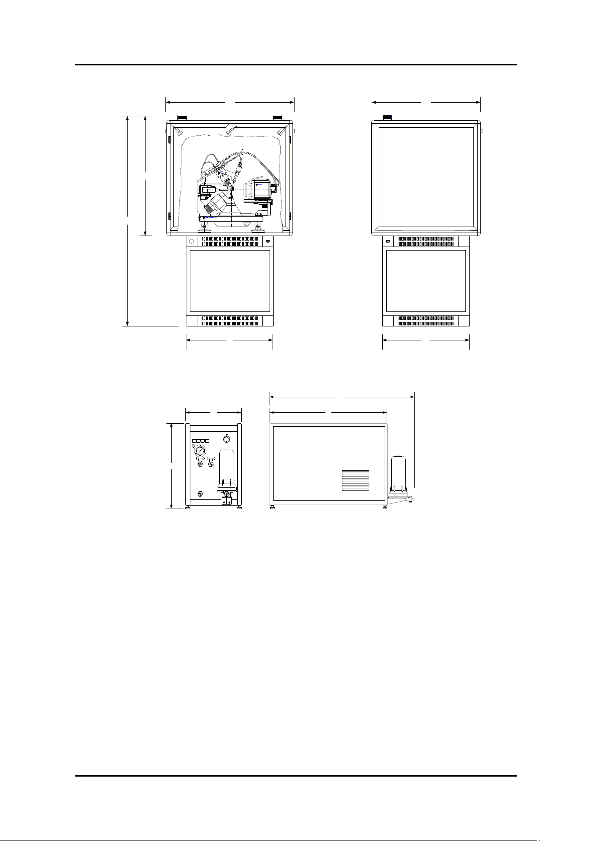
Xcalibur / Gemini Dimensions
115
200
116
80
100
80
54
37 75
96
ADDITIONAL INFORMATION
KMW3000C Dimensions
Figure 12.2.2 System and Component Dimensions
Xcalibur/Gemini Version 2.4
USER MANUAL Page 56
Page 65

12.2.2. Electrical Drawings
Drawing no
Title
Number
of pages
EW-02-00-001-A
KMW150CCD / KMW200CCD ELECTRICAL BLOCK SCHEME
1
EC-02-01-001-A
XCALIBUR / GEMINI STEPPING MOTORS CABLE
2
EC-24-01-001-A
XCALIBUR / GEMINI ENCODERS CABLE
2
EC-01-02-001-A
CCD POWER SUPPLY 230VAC SUPPLY CABLE
2
EW-03-02-001-A
KMW3000C ELECTRICAL CONNECTION SCHEME
1
EC-04-02-001-A
XCALIBUR / GEMINI CCD POWER SUPPLY TO PC (RS232)
2
EC-02-05-001-B
LCD MONITOR AND VIDEO MICROSCOPE POWER SUPPLY CABLE
2
EC-02-05-001-B
LCD MONITOR AND VIDEO MICROSCOPE POWER SUPPLY CABLE
2
EC-24-08-001-A
XCALIBUR / GEMINI REMOTE CONTROL CABLE
2
EC-04-09-001-A
XCALIBUR / GEMINI INTERFACE RS232 CABLE
2
EC-04-02-002-A
XCALIBUR / GEMINI FIP60 TO INTERFACE CABLE
2
EC-01-09-002-A
PC 230VAC SUPPLY CABLE
2
EC-04-02-003-B
CCD DETECTOR TEMPERATURE AND COLLISION
2
EF-00-01-001-A
XCALIBUR / GEMINI FAN PANEL- ELECTRICAL CONNECTION
1
EG-01-02-000-A
ALL SYSTEMS INSTALLATION
OD-1-04-01
CCD DETECTOR CONNECTIONS
1
OD-1-07-01
VIDEO MICROSCOPE KIT – BLOCK DIAGRAM
1
OD-1-07-02
EC-05-05-002-B VIDEO MICROSCOPE TO BNC „T‟ ADAPTOR CABLE
1
OD-1-07-03
EC-05-05-001-B BNC „T‟ ADAPTOR TO FRAME GRABBER CABLE
1
OD-1-07-04
EC-05-05-003-A BNC „T‟ ADAPTOR TO MONITOR CABLE
1
BCK-005-1
DETECTOR HEAD SUPPLY CABLE
1
BCK-006-1
DETECTOR HEAD COOLER CABLE
1
ADDITIONAL INFORMATION
Xcalibur/Gemini Version 2.4
USER MANUAL Page 57
Page 66

EG-01-00-013-A
GEMINI ELECTRICAL PANEL
1
EC-24-07-000-A
GEMINI FRONT ELECTRICAL PANEL
1
EC-24-07-010-A
GEMINI FRONT PANEL
1
EG-01-00-001-A
GEMINI PCB CONNECTIONS
1
EG-01-00-002-A
GEMINI PCB CONNECTIONS
1
EG-01-00-003-A
GEMINI PCB CONNECTIONS
1
EG-01-00-004-A
GEMINI PCB CONNECTIONS
1
EG-01-00-006-A
GEMINI PCB CONNECTIONS
1
EG-01-00-007-A
GEMINI PCB CONNECTIONS
1
EG-01-00-009-A
GEMINI PCB CONNECTIONS
1
EG-01-00-010-A
GEMINI PCB CONNECTIONS
1
EG-01-00-011-A
GEMINI PCB CONNECTIONS
1
EC-24-11-001-B
GEMINI PROTECTION CABINET SENSORS
1
EG-01-00-005-A
GEMINI WARNING LAMPS
1
EG-01-00-012-A
GEMINI WATER PANEL
1
Gemini
ADDITIONAL INFORMATION
Xcalibur/Gemini Version 2.4
USER MANUAL Page 58
Page 67

Appendices
Anode
Cu
1.540598(2)
1.544426(2)
1.39225(1)
1.00248
Mo
0.7093187(4)
0.713609(6)
0.632305(9)
1.00605
Compound name:
Ylid (2-Dimethylsulfuranylidene-1,3-indandione)
Compound formula:
(C11H10SO2)
Cell constants:
a= 5.947 Å
b= 9.026 Å
c= 18.399 Å
= = =90
To convert Fahrenheit to Celsius:
subtract 32 from F then multiply by
5/9
C=5/9(F-32)
To convert Celsius to Fahrenheit:
multiply by 9/5 then add 32
F=(9/5C)+32
To convert Celsius to Kelvin:
add 273.15
K=C+273.15
To convert Fahrenheit to Kelvin
first convert F to C then add 273.15
Appendix 1 X-ray Tubes Wavelengths
Appendix 2 Standard Crystal Parameters
ADDITIONAL INFORMATION
Appendix 3 Temperature Scales Conversion
Xcalibur/Gemini Version 2.4
USER MANUAL Page 59
Page 68

ADDITIONAL INFORMATION
Weekly Maintenance Record Sheet
Week
No.
Date of
maintenance
Name of person performing
test
Signature
Comments
1
2
3 4 5 6 7 8
9
10
11
12
13
14
15
16
17
18
19
Appendix 4 Maintenance Records
The attached record sheets are provided as examples of the type of records of maintenance checks
that should be completed for Xcalibur/Gemini. These records are to show only that maintenance has
been completed as directed in this manual. Other maintenance records should be kept as required by
any local, national or international regulations.
Xcalibur/Gemini Version 2.4
USER MANUAL Page 60
Page 69

ADDITIONAL INFORMATION
Weekly Maintenance Record Sheet
Week
No.
Date of
maintenance
Name of person performing
test
Signature
Comments
20
21
22
23
24
25
26
27
28
29
30
31
32
33
34
35
36
37
38
39
40
41
42
Xcalibur/Gemini Version 2.4
USER MANUAL Page 61
Page 70

ADDITIONAL INFORMATION
Weekly Maintenance Record Sheet
Week
No.
Date of
maintenance
Name of person performing
test
Signature
Comments
43
44
45
46
47
48
49
50
51
52 Monthly Maintenance Record Sheet
Month
Date of
maintenance
Name of person
performing test
Signature
Emergency
Stop Check
OK?
Y/N
X-ray radiation
check OK?
Y/N
Comments
1
2
3
4
5
6
USER MANUAL Page 62
Xcalibur/Gemini Version 2.4
Page 71

ADDITIONAL INFORMATION
7
8
9
10
11
12
Six Monthly Maintenance Record Sheet
Date of
maintenance
Name of person
performing test
Signature
Comments
Yearly Maintenance Record Sheet
Date of
maintenance
Name of person
performing test
Signature
Machine
parameter file
refined?
Y/N
CCD detector
vacuum
pumped?
Y/N
Comments
Xcalibur/Gemini Version 2.4
USER MANUAL Page 63
 Loading...