

Page 1
Installation Note
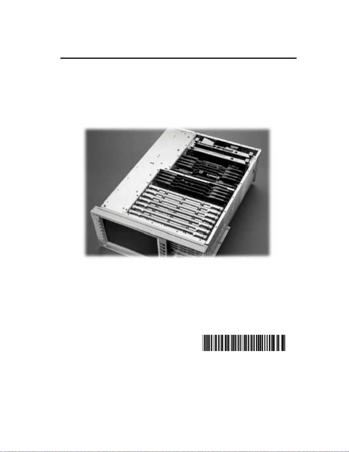
Agilent Technologies 8960 Wireless Communication Test Set
MDC Upgrade for E5515B/C
Kit Part Number: E5515BU-506 an d E5515CU-506
s
© Copyright 2006, Agilent Technologies Inc. Printed in the UK
Revision Date: June 13, 2007
Page 2

Notice:
The information contained in this document is subject to change without
notice.
Agilent Technologies makes no warranty of any kind with regard to this material,
including but not limited to, the implied warranties of merchantability and fitness for a
particular purpose. Agilent Technologies shall not be liable for errors contained
herein or for incidental or consequential damages in connection with the furnishing,
performance, or use of this material.
© Copyright 2007, Agilent Technologies Inc.
2
Page 3

Agilent Technologies 8960 W ireless Communication Test Set
MDC Upgr ad e for E5515B/C
Kit Part Number: E5515BU-506 an d E5515CU-506
Products Affected: . . . . . . . . . . . . . . . E5515B/C
Serial Numbers: . . . . . . . . . . . . . . . . . All
Options Required: . . . . . . . . . . . . . . . N/A
Applications Supported: . . . . . . . . . . All
To Be Performed By: . . . . . . . . . . . . . (X) Agilent Technologies Service Center
(X) Personnel Qualified by Agilent Technologies
( ) Customer
Estimated Installation Time: . . . . . . . 0.5 ho ur s
Estimated Verification Time: . . . . . . . 0.5 hours
Introduction
Installation includes the following major steps:
1. Disassembly
a. Remove the instrument covers.
b. Remove the old Measurement Down Converter.
2. Assembly
a. Inst a l l n e w M easurem en t D o w n C o nv e rter.
b. Install Option Label
3. Replace covers.
Installation Kit Parts List
Item Qty Description
1 1 Label
2 1 Measurement Down Converter Module
•
Label shou l d ha ve 506 printed on it.
3 1 Installation Instructions (this document)
Tools Requir ed
• TORX T-15 and T-20 drivers
Safety Considerations
WARNING
CAUTION Electros tati c discharge (ESD) can damage or destroy electronic
Before you disassemble the test s et, turn the power switch off and
unplug the power cord. Failure to unplug the test set can result in
personal injury.
components. All work on electronic assemblies should be performed at a
static-safe workstation.
3
Page 4

Disassembly:
Q
:
Remove outer cover and top cover for the 8960
1. Remove handles and rear bumpers.
2. Remove the screws on the rear pa nel holding outer cover.
3. S lide outer cover off.
4. Remove the 26 screws holding the top cover on and remove the cover.
Remove the old boards
1. Remove the old Measurement Down Converter module. Refer to the Replaceable
Parts List (E5515A/B/C/T) in the Troubleshooting and Repair section of the 8960
Assembly Level Repair area at: www.agilent.com/find/8960toolbox
location.
Assembly:
Install New Measurement Down Converter Module
1. Install the Measurement Down Converter as per dia gram on page 5 of the
Replaceable Parts Lis t document, referred to above.
Install Option Label
1. Install t he option label, 7121-7884, on the bac k of the instrument.
a. Write 506
b. Don’t cover up th e old option lab el if the options on the old label are not
also on the new label.
on the label if blank.
for board
Replace covers:
1. Replace the top cover and secure it with t he 26 s crews.
2. Slide the outer cover on.
3. Replace th e outer cov er s crews on the rear p anel.
4. Attach the rear bumpers and handles.
Adjust and Test and after Upgrade:
1. Turn on the tes t set and warm up for 30 minutes .
2. Perform the IQ Cali bra tion for SOURC E 1 & 2
3. Perform the Burst Mod Offset 1 Calibration
4. Perform the Digital Average Power calibration
5. Cycle th e power on the inst rument
6. Perform the Spectrum Monitor Calibration
7. Run the Test Set Verify software www.agilent.com/find/8960toolbox
after th e upgr a d e.
uestions and concerns
Technologies Support:
Phone: (800) 827-3848 (U.S. & Canada)
(509) 921-3848 (International)
Fax: (509) 921-3514
E-mail: spokane_service@agilent.com
Web: www.agilent.com/find/8960support
contact Agilent
to verify the test set
4
 Loading...