

Page 1

Assembly Level Repair
HP/Agilent Technologies
8922 Series GSM Test Set
Agilent Part No. 08922-90213
Printed in UK
January 1998
Page 2

© Copyright 1998, Agilent Technologies. All rights reserved. Reproduction, adaptation, or translation without prior
written permission is prohibited, except as allowed under the copyright laws.
Page 3

Introduction
Introduction
The HP/Agilent 8922 product family uses an assembly level repair service strategy. The
HP/Agilent 8922 may be sent to an Agilent Technologies Sales and Service office or may
be repaired on site. This book is used for both Agilent Technologies service and owner
service.
The HP/Agilent 8922 product family currently contains the HP/Agilent 8922A, HP/
Agilent 8922B, HP/Agilent 8922E, HP/Agilent 8922F, HP/Agilent 8922G, HP/
Agilent 8922H, HP/Agilent 8922M and HP/Agilent 8922S. There are differences in both
the hardware and in the operation. In examples and task sequences this book presents
general usage, and graphical instrument representations may not exactly match the HP/
Agilent 8922 that you are servicing.
Repairing the HP/Agilent 8922
To repair the HP/Agilent 8922, follow the chapters in this book starting at the beginning
and following the “where to go next” guidelines.
Book Organization
This book contains problem identification sections, assembly replacement sections,
reference information and concept information. The chapters are sectioned in three parts;
Service Procedures, Reference Information and Theory. This sectioning helps to identify
the type of information found in a group of chapters.
i
Page 4

Introduction
ii
Page 5

Contents
1 Localizing the Problem
2 Running Diagnostics
Introduction i
Introduction 1-2
Localizing the Problem - Flow Chart (Power-Up) 1-3
Power-Up Checks 1-4
If Power-Up Checks FAILED 1-5
If Power-Up Happened Correctly 1-10
Introduction 2-2
Running Memory Card or ROM Based Diagnostics 2-3
Loading and Running the Ram Test 2-7
3 Verifying Performance
Introduction 3-2
Installing and Operating the Software 3-2
Using the Compatibility Switch for the HP/Agilent 8922F/
H or M/S 3-3
4 Using the HP/Agilent 83210A Service Kit
Introduction 4-2
Configuring the RF Extender 4-3
Extending Modules 4-5
Making Measurements 4-6
5 Troubleshooting the Controller/Display
Introduction 5-2
Parallel Bus 5-3
Serial Bus 5-4
Display 5-5
Keyboard 5-6
Contents-1
Page 6

Contents
6 Troubleshooting the Power Supply
7 Adjustments and Calibration
Introduction 6-2
Power Cord Verification 6-3
Line Voltage Selection / Line Fuse Replacement 6-5
Transformer / Power Switch 6-6
A28 Power Supply 6-7
Where To Go Next 6-8
Introduction 7-2
Timebase Adjustments 7-3
Periodic Calibrations 7-5
Sum Loop Adjustment Procedure 7-6
8 Assembly and Disassembly Procedures
Introduction 8-2
Top and Bottom Cover Removal 8-3
Inside Protective Covers 8-4
AF, Digital and RF Assemblies Removal 8-5
A1 Front Panel Removal 8-7
A10 Power Supply Regulator Removal 8-9
A11 Receiver Mixer Removal 8-10
A12 Pulse Attenuator Removal 8-12
A21 GPIB Interface Removal 8-14
A22 Display Removal 8-16
A23 Input Section Removal 8-18
A24 Attenuator Removal 8-19
A28 Power Supply Removal 8-20
Fan Removal 8-22
Transformer Removal 8-24
Contents-2
Page 7

Contents
9 Replacing a Part
10 Service Screen
11 Self-Test Error Messages
Introduction 9-2
Replaceable Parts 9-3
Firmware Upgrades 9-29
Introduction 10-2
Introduction 11-2
12 Module I/O Specifications
Introduction 12-2
A2 Audio Analyzer 2 12-3
A3 Audio Analyzer 1 12-5
A4 Modulation Distribution 12-8
A5 Premodulation Filter and NSM 12-10
A6 Signaling Source/Analyzer 12-13
A9 Global Test and Demod 12-15
A11 Receiver Mixer 12-19
A13 Output 12-22
A14 Pulse Driver 12-24
A15 Reference 12-26
A16 Receiver 12-32
A18 Spectrum Analyzer 12-36
A19 Measurement 12-38
A23 Input (HP/Agilent 8922A.B,E,F,G,H) Only 12-43
A23 Input (Agilent 8922M/S Only) 12-47
A25 Sum Loop 12-50
A17, A26 Step Loop 12-53
A27 DAC/Upconverter 12-56
Contents-3
Page 8

Contents
13 Instrument Block Diagrams
14 Block Diagram Theory of Operation
A28 Power Supply 12-58
A33 Hop Controller 12-59
Introduction 13-2
Introduction 14-2
Technical Discussion 14-3
Block Diagram 1 14-4
Block Diagram 2 14-9
Block Diagram 3
HP/Agilent 8922B Only 14-15
Block Diagram 4 14-17
Block Diagram 5 14-18
15 Diagnostics Theory
Contents-4
Introduction 15-2
AF_DIAGS 15-3
RF_DIAGS 15-5
MS_DIAGS 15-11
GSM and DCS Diagnostic Tests 15-12
Interpreting Results 15-13
Page 9

Contents
16 Measurement Theory
17 GSM Theory
Index 1
Introduction 16-2
Introduction 17-2
The GSM System 17-3
E-GSM, DCS1800 and PCS1900 Systems 17-4
Contents-5
Page 10

Contents
This Page Intentionally Left Blank
Contents-6
Page 11

1
Localizing the Problem
1-1
Page 12

Localizing the Problem
Introduction
Introduction
This chapter helps to determine if a problem actually exists and which section of the
instrument has a problem.
This chapter comprises of four sections.
❒ Localizing the Problem Flow Chart (Power-Up)
❒ Power-Up Checks
❒ If Power-Up Failed
• Power-Up Self Test Diagnostics
❒ If Power-Up Happened Correctly
• Checking the RF Analyzer using the RF Generator
• Checking the RF Analyzer using the AF Generator
1-2
Page 13
Localizing the Problem
Localizing the Problem - Flow Chart (Power-Up)
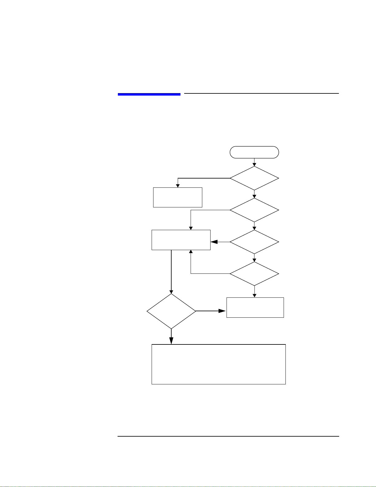
Localizing the Problem - Flow Chart (Power-Up)
See "Power Up Checks", in this Chapter, for details of the steps given in the flow chart
below.
Power On
NO
Goto;
"Troubleshooting the
Power Supply"
Goto;
"Power-Up Self Test
Diagnostics"
Failure
Reported by
Diagnostics ?
YES
Goto the relevant trouble shooting section;
NO
NO
6 seconds?
NO
NO
Controls OK?
Goto;
"If Power-Up
Happened Correctly"
Fan On?
YES
Beep after
YES
Messages
OK?
YES
Keys &
YES
• "Trouble Shooting The Controller/Display" - Chapter 5.
• "Trouble Shooting The Power Supply" - Chapter 6.
• "Running Diagnostics" - Chapter 2
Figure 1-1 Localizing the Problem - Flow Chart
1-3
Page 14
Localizing the Problem
Power-Up Checks
Power-Up Checks
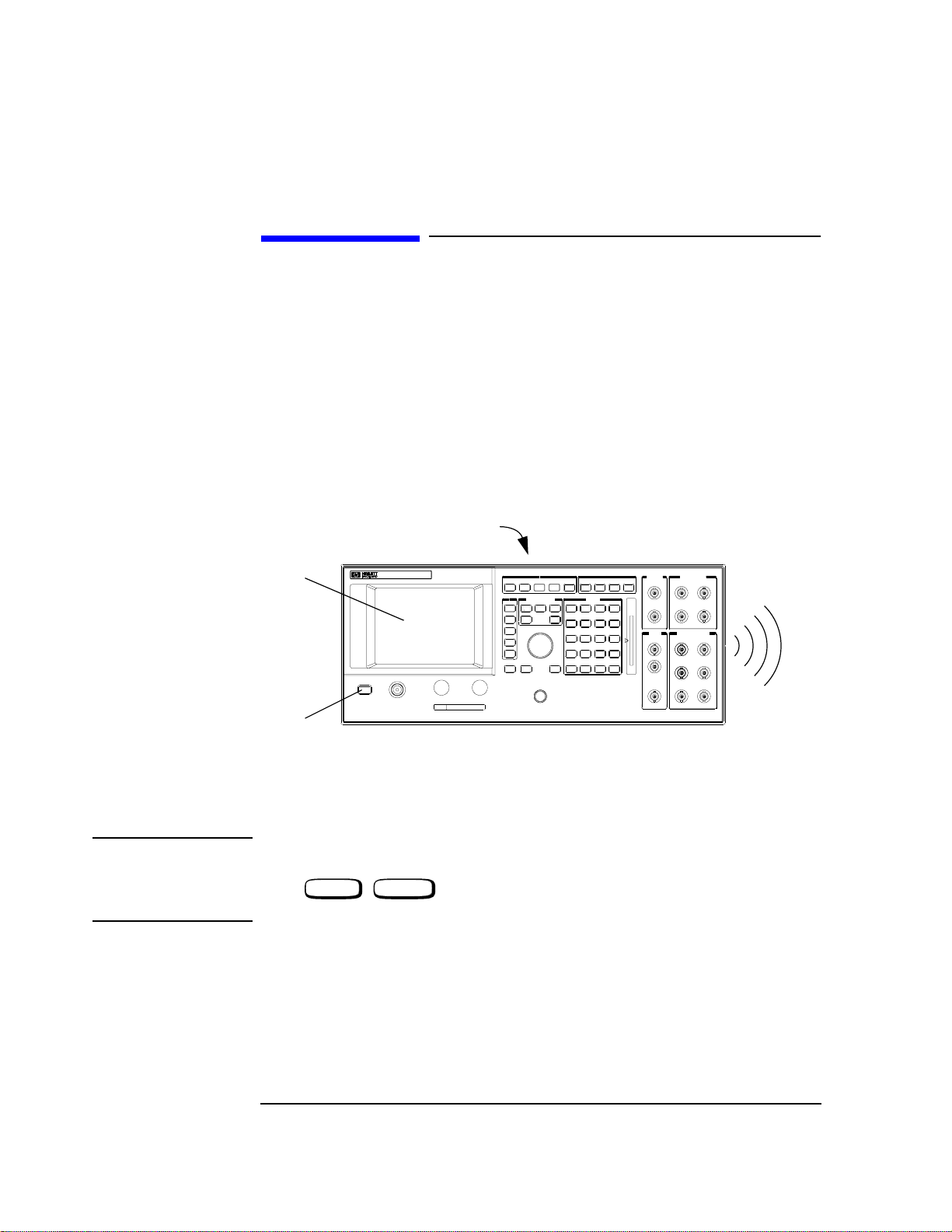
The following checks show whether the instrument is powering up correctly.
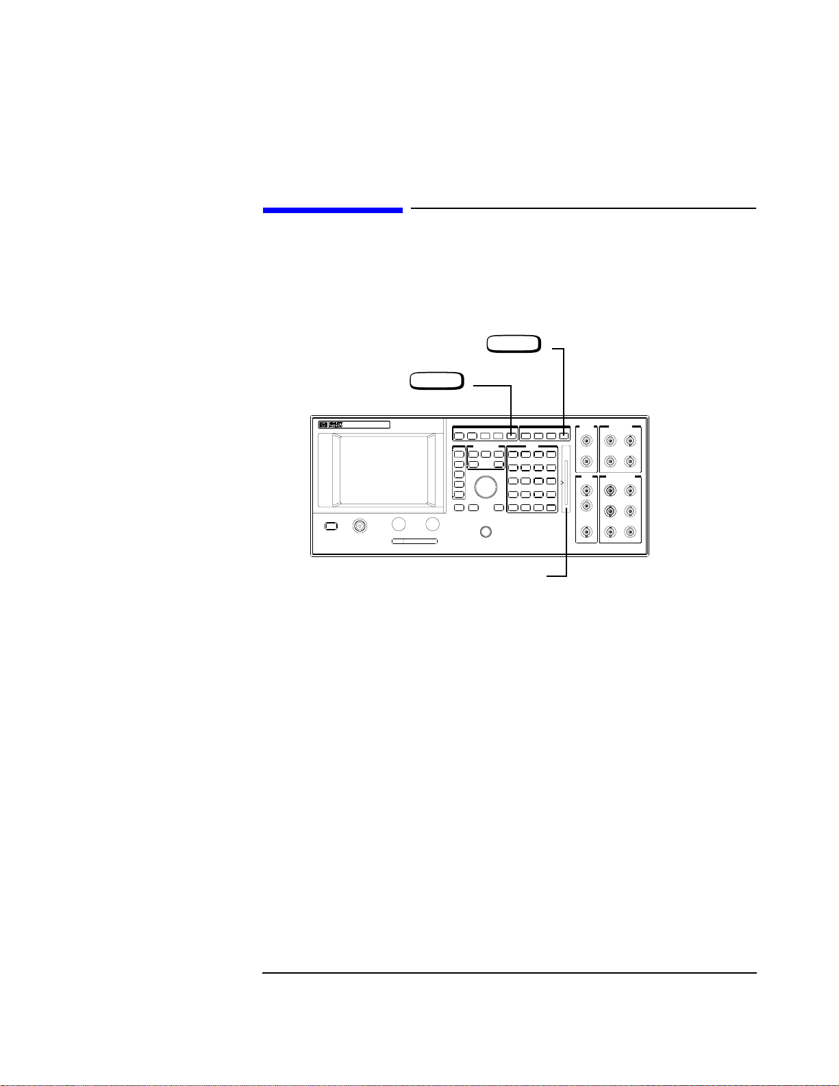
(a) Depress the power button on the front panel (see diagram).
(b) Check that the fan on the rear panel is working.
(c) Listen for a single “beep” after pressing the power switch. This can be from 6 to 20
seconds, depending on model type.
(d) Check the display on the front panel for any error messages. (The normal message
which will appear is “All host processor self-tests passed.” and/or "Frequency
Reference Cal lost. Perform Reference Calibration".)
(b)
(d)
(a)
Figure 1-2 Power-Up Checks - Agilent 8922x
NOTE If an error message appears after power up it may not be the only message
which has appeared. Only the last message will be shown on this message line.
Press , (MSG) to access the message screen for a list of all the
error messages.
SHIFT TESTS
(Rear Panel Vent)
(c)
"Beep"
1-4
Page 15
Localizing the Problem
If Power-Up Checks FAILED
If Power-Up Checks FAILED
If the power up checks failed, continue with this section.
❒ If the fan did not start, see "Troubleshooting the Power Supply", Chapter 6.
❒ If the fan started, but any of the other power-up checks failed, see "Power-Up Self Test
Diagnostics".
❒ If an error message occurs, refer to the Agilent 8922x Users Guide for additional
information.
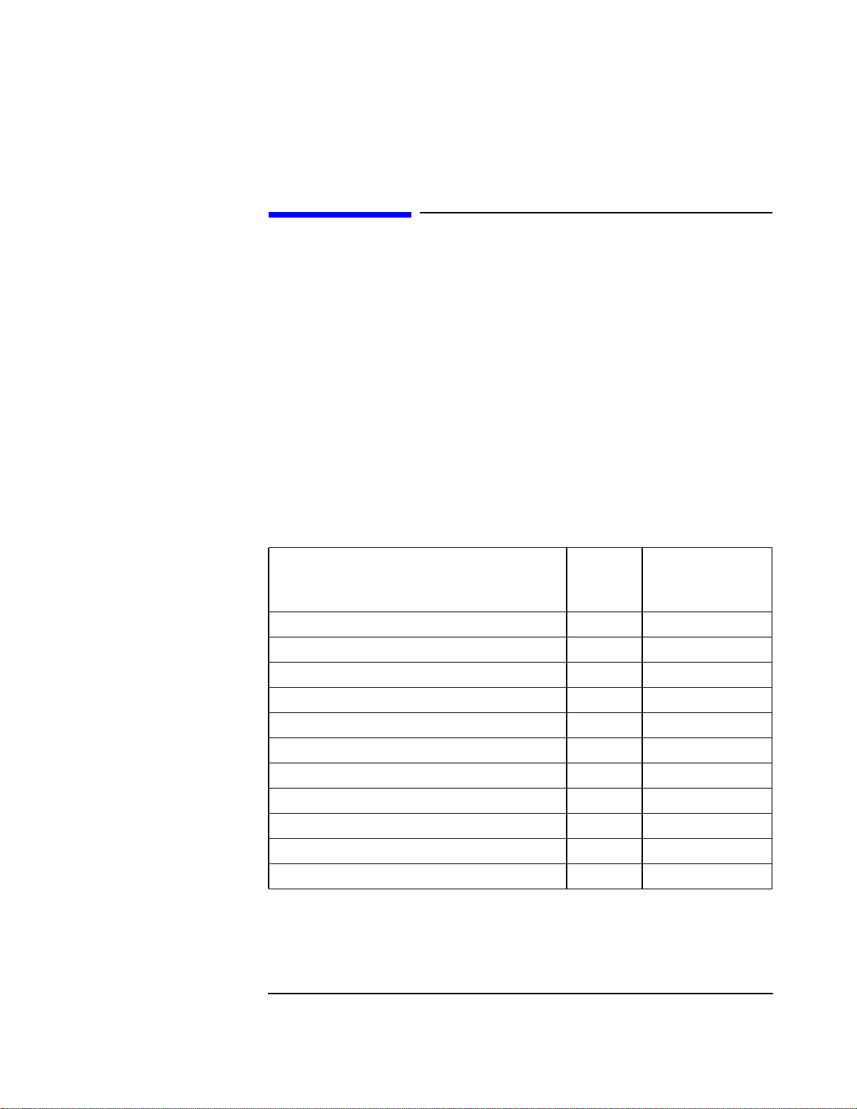
Error Message Numbers
If the error message refers to a self test error it will be of the form:
One or more self tests failed: Error Code XXXX
Where xxxx corresponds to the error message number shown in the table below.
Table 1-1 Error Message Numbers
Failure
Fatal Error - Host Processor Failure 0002 A7 Controller
Fatal Error - ROM Checksum Failure 0004 A8 Memory
Fatal Error - RAM Failure 0008 A8 Memory
Fatal Error - RAM Failure 0010 A8 Memory
Fatal Error - Timer Failure 0020 A7 Controller
Real Time Clock Failure 0040 A8 Memory
Keyboard Failure 0080 A1 Keyboard
Serial I/O Failure 0100 A21 GPIB
Internal Serial Bus Communication Failure 0200 Serial Bus
CRT Failure 0400 A19 CRT Drive
Miscellaneous Hardware Failure 0800 Miscellaneous H/W
Error
Number
Suspect Assembly
1-5
Page 16
Localizing the Problem
If Power-Up Checks FAILED
Power-Up Self Test Diagnostics
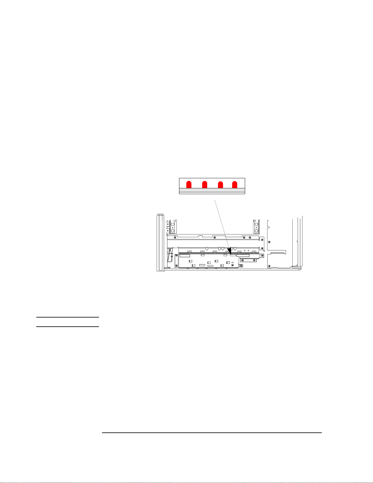
If the power-up sequence failed, the power-up self-tests can be re-run with the covers off.
The LED’s on the controller board give the results of the power-up self-test.
(a) Remove the instrument covers. Refer to the section "Top and Bottom
Covers", Chapter 8, for details.
(b) Power up the instrument.
(c) Read the LED sequence given on the controller board. These LED’s can be
read with the shields in place (refer to the diagram below)
Location of LED’s
3210
Front Panel
(View from top)
Figure 1-3 Self Test LED Location
NOTE For multiple failures, the patterns for each failure will appear in sequence.
1-6
Page 17
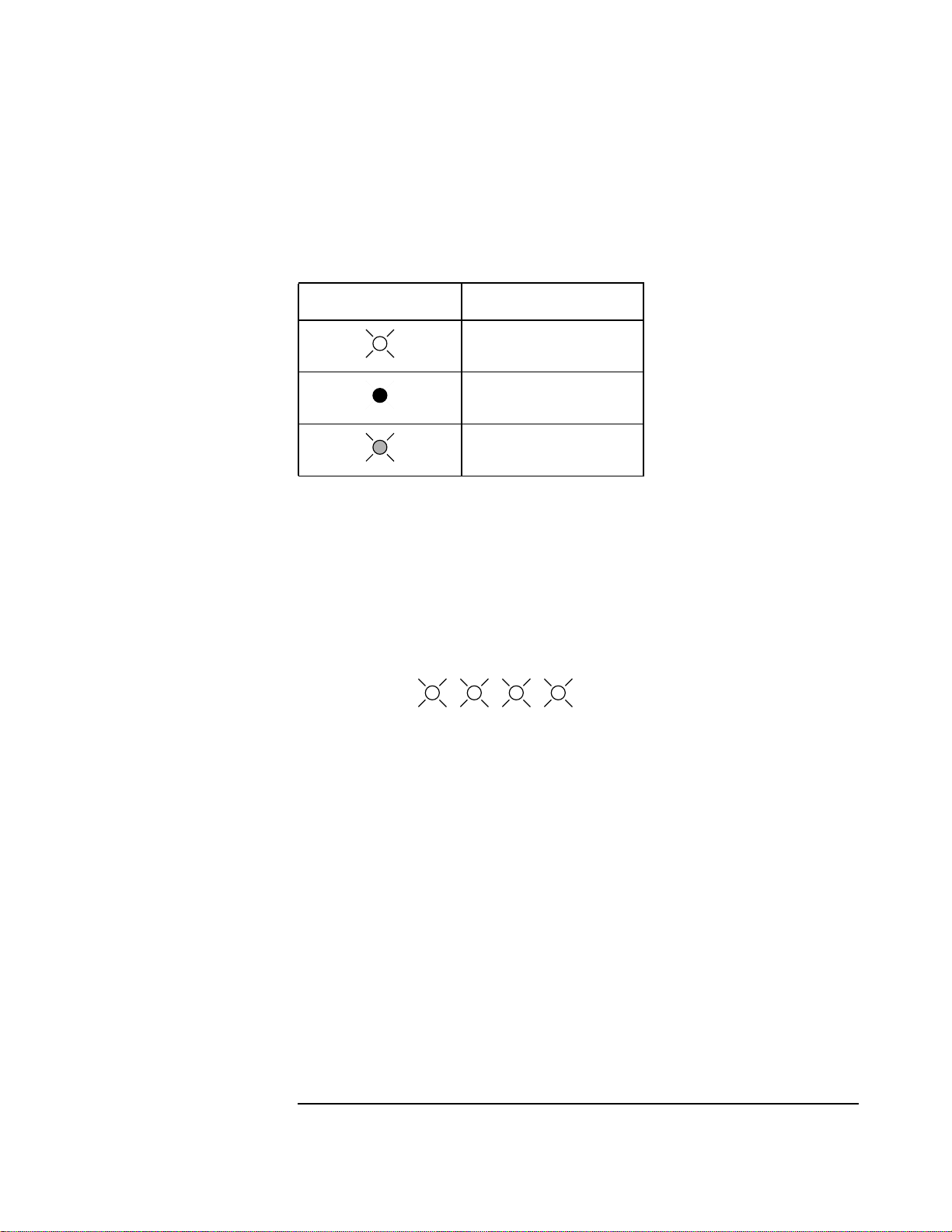
The following conventions are used to represent the LED’s throughout this chapter.
Table 1-2 LED Conventions
LED shown in tables Represnts
LED Sequences
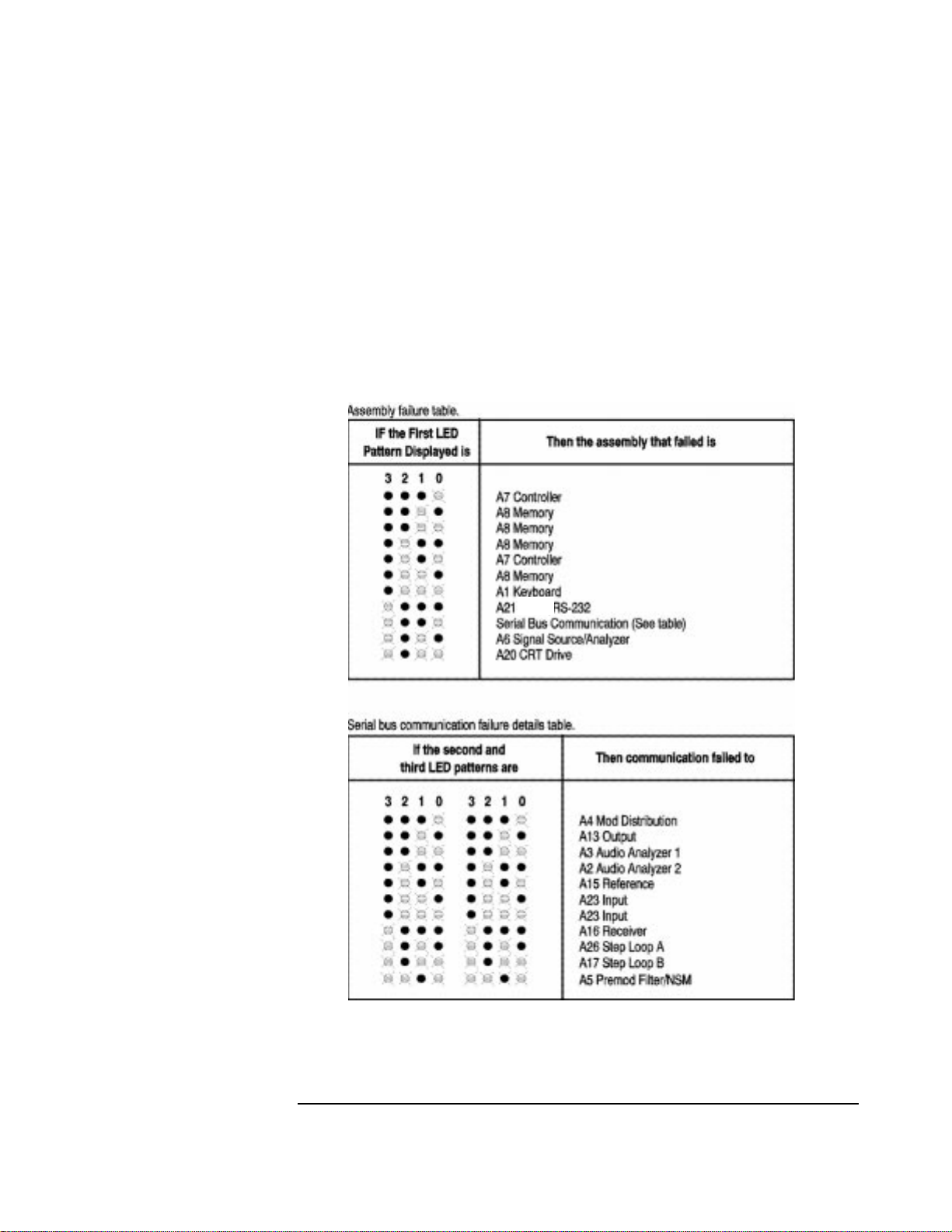
The LED error sequence will show two states, pass or fail, which are outlined below. The
suspect assembly is given in the following tables, before moving on consult the section
"Self-Test Diagnostic Result".
Localizing the Problem
If Power-Up Checks FAILED
A ’lit’ LED
An ‘off’ LED
A flashing LED
No Failures
Detected The LED’s will light for approximately 10 seconds, then all will turn
off.
3210
Lit for 10 seconds.
Failure Detected 1 The LED’s will initially all light.
2 The next pattern blinks rapidly, and shows that an assembly has
failed.
3 The third sequence flashes twice and gives further information on
the area of the board that has failed.
4 The LED’s will light then go out.
1-7
Page 18

Localizing the Problem
If Power-Up Checks FAILED
Table 1-3 Sequence of LED Patterns
3210
1
3210
2 Assembly failure.
3210 3210
3
3210 3210
4 No more errors.
NOTE 1. The third patterns are only documented for a serial bus communication failure. This is
represented by the two outside LED’s flashing.
2. The second and third patterns will be the same. It will appear as if the same pattern has
flashed twice.
For more than one error in the Agilent 8922x the LED’s will flash in the same sequence for
each assembly that is faulty.
Serial Bus
Communication
Failures
1-8
Page 19
Localizing the Problem
If Power-Up Checks FAILED
Where to Go Next
❒ If the LED’s did not light at all, go to Chapter 6, "Troubleshooting the Power Supply".
❒ If an error messgae occurs, use it in Chapter 2, "Running Diagnostics" to choose which
diagnostic test to run. See also Chapter 11 "Self Test Error Messages".
❒ If this section is used due to display problems, go to Chapter 5 "Troubleshooting the
Controller/Display" before the error messages are repaired.
GPIB/
1-9
Page 20
Localizing the Problem
If Power-Up Happened Correctly
If Power-Up Happened Correctly
If power-up happened correctly and no problem is indicated, this section is used to functionally check most of the hardware. The generators are checked first with external measurements, then the analyzers are checked with the generator. The RF Generator is
checked at 935 MHz and 10 dBm. The AF Generator is checked at 1 kHz and 1 V. These
checks are for indication only, performance tests in Chapter 3, “Verifying Performance”,
will test specifications.
NOTE If you possess an Agilent 8922S or Agilent 8922M, you should first re-configure your
instrument as an HP/Agilent 8922E or HP/8922G. To do this, select the following keys:
• CONFIG (this is accessible from the Cell Control screen in the bottom right-hand
corner).
• Compatible, select (HP 8922E or HP 8922G)
PRESET
•
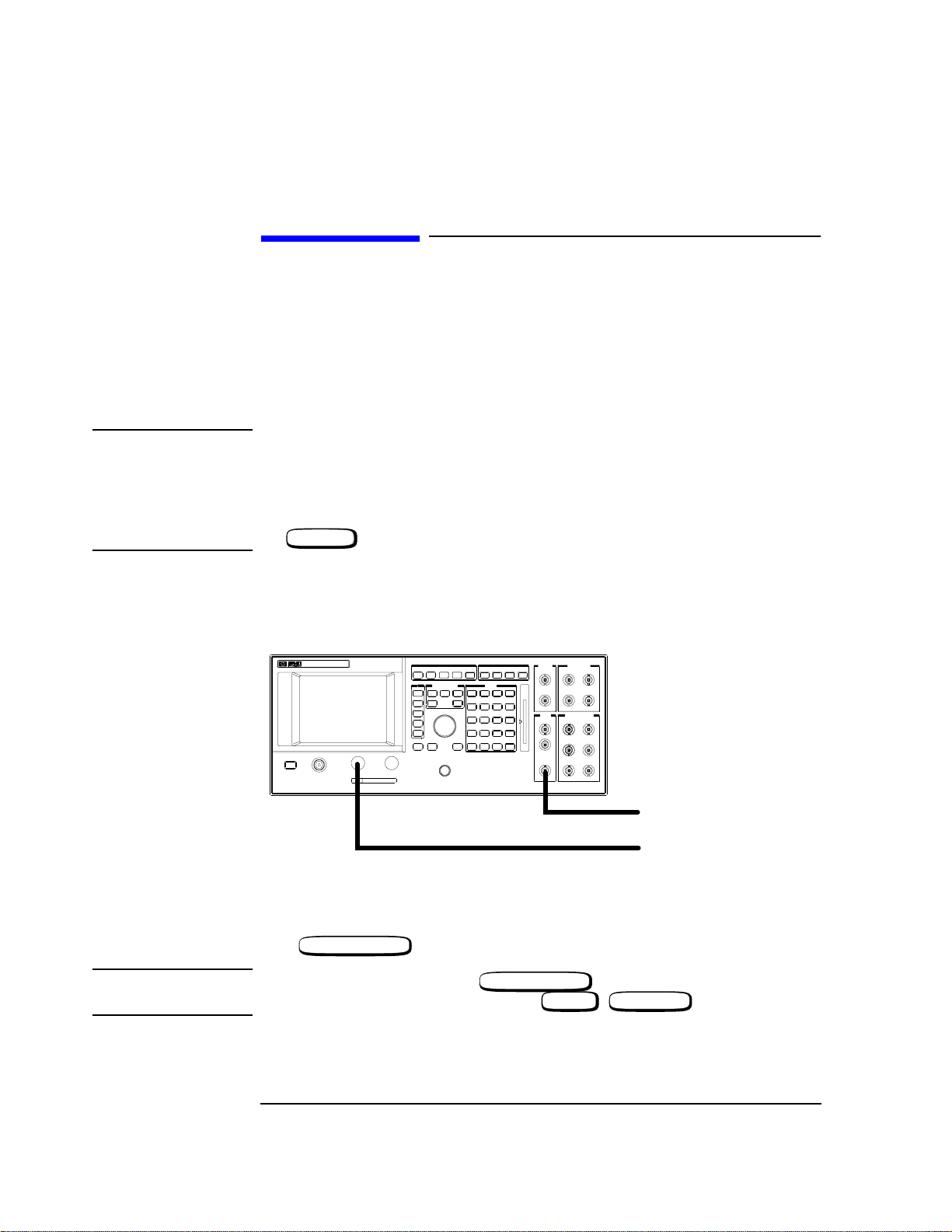
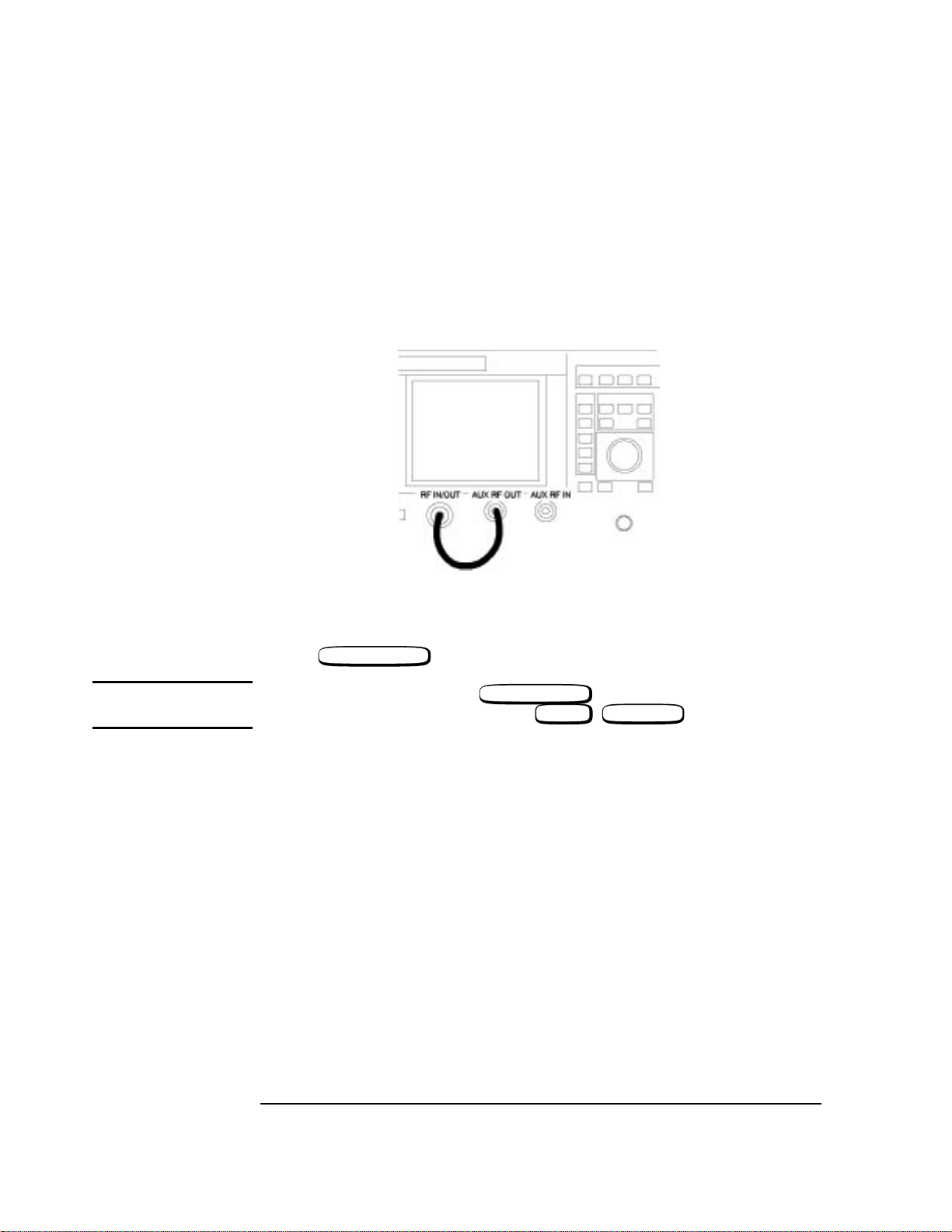
Referring to Figure 1-4, ensure the connections are made.
AUDIO RF OUT
AUDIO OUT
Figure 1-4 Front Panel Connections
RF GEN/RF ANL
Press .
NOTE On the HP/Agilent 8922A/B, press .
On the HP/Agilent 8922E/F/G/H/M/S, press , (RFG/RFA).
RF GEN/RF ANL
SHIFT CELL CNTL
AF To Oscilloscope
RF To Spectrum Analayzer
1-10
Page 21
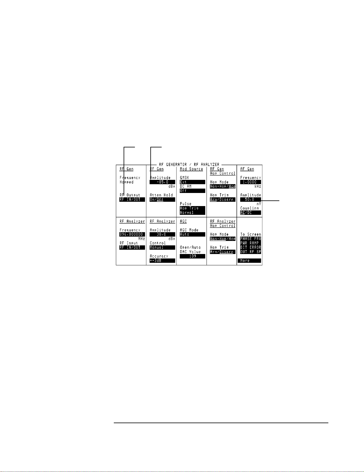
Highlight the RF Output field (1).
Select AUX RF OUT from the list of choices.
Set the RF Generator Amplitude field to 10 dBm (2).
Set the AF Generator Amplitude field to 1 V (3).
Localizing the Problem
If Power-Up Happened Correctly
1
Figure 1-5 RF Analyzer Settings
2
Where to Go Next
• If the generators are within specifications, go to the next section, “Checking the RF
Analyzer Using the RF Generator”.
• If one or both of the generators appear to be faulty, go to Chapter 2, “Running
Diagnostics” and run the appropriate tests.
3
1-11
Page 22
Localizing the Problem
If Power-Up Happened Correctly
Checking the RF Analyzer Using the RF Generator
This section tests the RF Analyzer using the RF Generator as a signal source. This task
assumes the same setting used in the previous section.
• Connect the RF In/Out to the Aux RF Out.
Figure 1-6 Front Panel Connections for the RF Analyzer
RF GEN RF ANL
Press .
NOTE On the HP/Agilent 8922A/B, press .
On the HP/Agilent 8922E/F/G/H/M/S, press , (RF GEN RF ANL).
RF GEN RF ANL
SHIFT CELL CNTL
1-12
Page 23
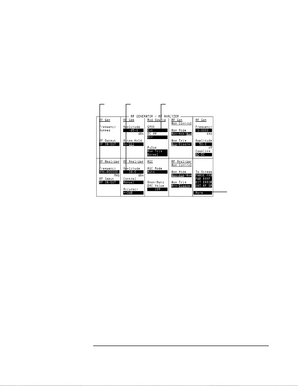
If Power-Up Happened Correctly
• Set the RF Analyzer Frequency field to 935 MHz (1).
• Set the RF Analyzer Amplitude field to 10 dBm (2).
• Set the Mod Source GMSK field to Off (3).
• Select More in the bottom right-hand corner of the screen (4).
12 3
Localizing the Problem
Figure 1-7 RF Generator/Analyzer Settings
4
1-13
Page 24
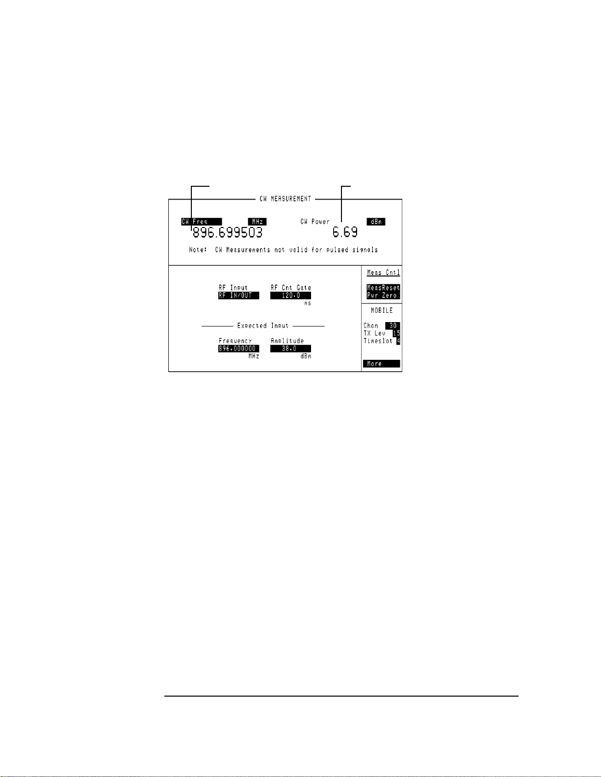
Localizing the Problem
If Power-Up Happened Correctly
• SelectCW/AF ANL from the list of choices, and read the CW Freq (5) and CW Power
(6) fields.
56
Figure 1-8 CW Readings
Where to Go Next
• If the analyzer measurement was within the specification, go to the next section,
“Checking the AF Analyzer using the AF Generator”.
• Ifthemeasurementwasfaulty,gotoChapter2,“RunningDiagnostics”,andrunthetest
related to the RF Analyzer.
1-14
Page 25
Localizing the Problem
If Power-Up Happened Correctly
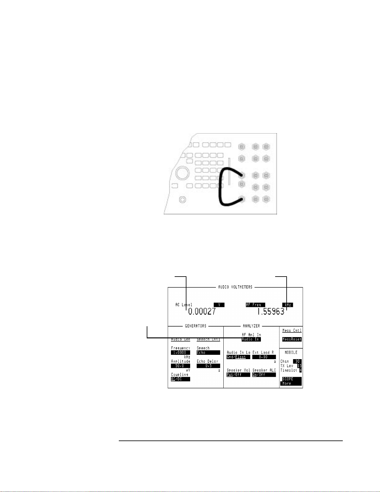
Checking the AF Analzyer Using the AF Generator
This section tests the AF Analyzer with the AF Generator as a source. The AF Generator
settings are the same as the first task, and displays the CW MEAS/AF ANL screen.
• Connect the AUDIO OUT to the AUDIO IN.
Figure 1-9 Front Panel Connections for the Audio Check
• Select More and from the list, select CW MEAS/AF ANL.
• Highlight AF Anl In and select AUDIO IN (1).
• Read the AC Level (2) and the AF Freq (3) reading.
2
1
Figure 1-10 Audio Measurements
3
1-15
Page 26

Localizing the Problem
If Power-Up Happened Correctly
Where to go next
• If the analyzer measurement was within specification, go to Chapter 2, “Running
Diagnostics” and run all the tests.
• If the analyzer measurement was faulty, go to Chapter 2, “Running Diagnostics” and
run the tests relating to the AF Analyzer.
1-16
Page 27

2
Running Diagnostics
2-1
Page 28

Running Diagnostics
Introduction
Introduction
There are two types of diagnostics for the HP/Agilent 8922: diagnostic tests and the HP/
Agilent 8922B specific “RAM Test”. The latter is appropriate for the HP/Agilent 8922B
only. The diagnostic tests are contained either on the memory card, part number 0892210003 or in ROM memory for instruments with firmware revision code A.03.00 and
above. The HP/Agilent 8922B specific “RAM Test” is contained on the “08922-10001,
8922B Driver” disk supplied with the HP/Agilent 8922B.
Most of the diagnostic tests relate to a fault in a specific instrument section. Therefore, if
chapter 1 identified a specific section of the instrument, only those tests need to be run.
The diagnostic tests whose names begin with E or G are specifically for the HP/Agilent
8922E/G. The other tests are for any HP/Agilent 8922.
This chapter comprises two sections. The first section, “Running Memory Card or RAM
Based Diagnostics”, shows how to load and run the memory card based or ROM based
diagnostics. The second section, “Loading and Running the RAM Test”, shows how to
load and run the HP/Agilent 8922B RAM test. Equipment requirements and installation
procedures are given in the HP/Agilent 8922B User’s Guide, Part Number 08922-90020.
This chapter uses the diagnostic test names from an early memory card revision. ROM
based diagnostic test names may differ from the names used in this chapter.
2-2
Page 29
Running Diagnostics
Running Memory Card or ROM Based Diagnostics
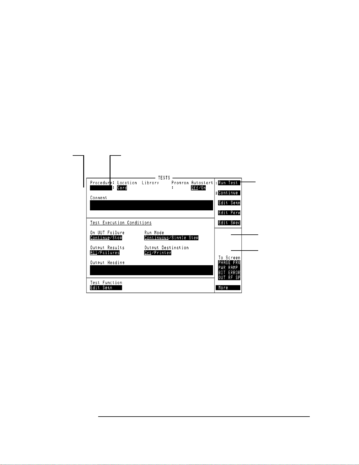
Running Memory Card or ROM Based Diagnostics
Do these steps in the order shown
1 - Press
3 Press
2 - Insert Memory Card (Optional)
TESTS
PRESET
2-3
Page 30
Move cursor here and
6
press knob.
Running Diagnostics
Running Memory Card or ROM Based Diagnostics
For Memory Cards:
4
If CARD is displayed, go to step 6, if not move the cursor to this field, press knob and continue at step 5.
Move cursor here and
8
pressknob. Followthe
instructions to start.
To select another test;
• To select another tests from thesame program use
the RESUME user key.
• To select a test from another program press
TESTS key and begin at step 6.
Select CARD
5
Select,
7
AF_DIAGS,
RF_DIAGS1,
MS_DIAGS1,
CAL_REV,
LOOP_BACK
2-4
Page 31

Running Memory Card or ROM Based Diagnostics
Reading Memory Card Diagnostic Test Results
Running Diagnostics
Test Results
Assemblies suspected to be defective
Probability Indicator
Troubleshoot the assembly with the highest
probability first and re-run test. Continue this
process withall assemblies listed until thedefect is
found. See also Chapter 15 "Diagnostic Theory'.
2-5
Page 32

Running Diagnostics
Running Memory Card or ROM Based Diagnostics
Selecting Memory Card Diagnostic Test Execution Conditions
BEFORE RUNNING A TEST
Specifies whether to run measurements continuously or
stop after completion of each measurement. This choice
can be modified when a diagnostic program is running.
Specifies whether to stop
testing or continue when a
failure occurs. This choice
can be modified when a
diagnostic program is
running.
This feature is not used by
the diagnostic program.
Specifies whether to print diagnostic test results.
WHILE RUNNING A TEST
These options are used for controlling various
parts of the tests. These options can be changed
depending on the test program. They are
selected by using the cursor and knob.
Where to Go Next:
If any high-probability failures occurred, those assemblies can be replaced and the test rerun. When the tests pass, the performance tests can be run to verify performance (refer to
Chapter 3). If low-probability failures occur, the performance tests can be run for further
indication or measurements can be made to individual assemblies using Chapters 4, 12
and 13.
2-6
Page 33

Running Diagnostics
Loading and Running the Ram Test
Loading and Running the Ram Test
Your HP/Agilent 8922B comes with software to test the Data Buffer.
Loading the RAM Test
1 Locate the floppy disk labeled “08922-10001, 8922B Driver.”
2 Insert the disk into the drive.
3 Type MSI A: (substitute your drive specifier for A: if your drive is not drive A) and
press .
4 Type LOAD “DRIVER22B”,1 and press .
The Data Buffer Driver will now be loaded and will begin to run.
5 Press
ENTER
ENTER
K3, "Test RAM
6 Use the cursor to select the output device.
7 Select the area of RAM to test and Press .
K0, "Accept
8 Repeat selection for each area of RAM.
Where to go next
• If any of the RAM areas tested bad go to chapters 8 and 9.
Selecting from a List
• Use and to scroll through the list. A beep will sound when you reach an end
⇓
⇓
of the list.
• Use or to move to the first item in the list.
• Use or to move to the last item in the list.
• Use or to select the current item and move to the next field on the
SHIFT
SHIFT
ENTER
⇓
PG UP
⇓
PG DOWN
⇓
screen.
• Use to select the current item and move to the previous field on the screen.
⇓
2-7
Page 34

Running Diagnostics
Loading and Running the Ram Test
This Page Intentionally Left Blank
2-8
Page 35

3
Verifying Performance
3-1
Page 36

Verifying Performance
Introduction
Introduction
Because of the specialized nature of the HP/Agilent 8922 and the equipment required to
support it, it is recommended that calibration and repair be performed only by specially
equipped Agilent Technologies service centers.
A list of specifications and verfication tests can be found in the HP/Agilent 8922x User’s
Guide.
Verification
Performance Test Software provided with the product is used to verify the electrical
performance of the HP/Agilent 8922 GSM Test Set. If the instrument passes this
verification, its operation and specifications are assured within the measurement
uncertainties provided in the performance test print out.
Installing and Operating the Software
Performace Test Software
This is supplied on a 3.5-inch, double-sided floppy disk and is written to run with BASIC
5.0 and later. Modifications to the program should be limited to changing the default
addresses and storing copies for back-up purposes.
Understanding the Tests
Test Descriptions contains a description of each test that is performed by the Performance
Test software. This description is intended to help locate problems if the software fails to
execute properly or to help users understand the test methodology that is used in each
performance test. The descriptions are not step by step procedures for manual
performance tests.
3-2
Page 37

Verifying Performance
Using the Compatibility Switch for the HP/Agilent 8922F/H or M/S
To Load the Program in the Agilent 8922M/S.
To verify the performance of the HP/Agilent 8922H/M you need to convert the instrument
back from an HP/Agilent 8922G, or convert the HP/Agilent 8922F/S to an HP/Agilent
8922E.
You are now ready to run the Performance Test Software.
1) Put the disk in the disk drive.
2) Type ``LOAD "PT_8922"'', press ENTER.
After you have completed the Performance Tests, return the instrument back to the
HP/Agilent 8922F/S or HP/Agilent 8922H/M using the same process in reverse.
Using the Compatibility Switch for the
HP/Agilent 8922F/H or M/S
Back Conversion
To turn the instrument from the HP/Agilent 8922H/M or HP/Agilent 8922F/S back to an
HP/Agilent 8922G or an HP/Agilent 8922E, select the following keys:
❒ CONFIG (this is accessible from the Cell Control screen in the bottom right-hand
corner).
❒ Compatible, select HP 8922G or HP 8922E
❒ HP-IB Adrs (22)
❒ PRESET
The instrument is now set up as an HP/Agilent 8922G or HP/Agilent 8922E and ready for
Performance Verification testing.
Forward Conversion
To return the instrument from an HP/Agilent 8922G back to an HP/Agilent 8922H/M or
an HP/Agilent 8922E to an HP/Agilent 8922F/S, select the following keys:
❒ More (this is accessible from the Cell Control screen in the bottom right-hand corner).
Scroll down the list and select CONFIG.
❒ Compatible, select HP 8922H/M or HP 8922F/S
❒ HP-IB Adrs (14)
❒ PRESET
The instrument is returned to an HP/Agilent 8922H/M or HP/Agilent 8922F/S.
3-3
Page 38

Verifying Performance
Using the Compatibility Switch for the HP/Agilent 8922F/H or M/S
To Configure the GPIB Addresses
1) With the program loaded, type ``EDIT DEFAULT_ADDRESS'', press ENTER.
2) Modify each line to indicate the proper instrument address (700-730).
It is now possible to re-store the program as "PT_8922" or store it under a different name.
To Run the Program
1) Type ``RUN'', press ENTER.
2) Follow the directions as they appear on the screen.
Notes on Running the Program.
The first screen which appears is the GPIB status of each piece of test equipment that is
supported. It is only necessary to have the instruments responding that will be used in each
particular test. Make certain that each instrument you will be using is responding at the
proper address. Duplicate addresses may make an instrument appear to be responding but
this is not allowed. Press "I" (for Ignore) to continue past this screen.
The second screen prompts you for the instrument model. If you have disk 08922-10006,
select HP 8922G (for HP/Agilent 8922H/M performance testing) or HP 8922E (for
HP/Agilent 8922F/S performancetesting). The third screen which will appear is the main
Performance Tests selection menu. Three options are available on this screen:
❒ Select the performance test to run, remember the test instruments and UUT must be
responding over GPIB.
❒ Turn the printer function ON or OFF. If the printer function is turned on it must be
responding over GPIB or the program will lock up.
❒ Exit from the program.
Press the key corresponding to the option that you would like to perform.
The other screens that appear are connection instructions, error messages and output
results.
3-4
Page 39

4
Using the HP/Agilent 83210A Service Kit
4-1
Page 40

Using the HP/Agilent 83210A Service Kit
Introduction
Introduction
This section is a supplement to the diagnostics program for troubleshooting the
HP/Agilent 8922 to the assembly level. The extender boards should be used when the
diagnostics cannot correctly isolate a defective assembly, or when it is necessary to verify
the module level performance of the HP/Agilent 8922.
The section provides the information necessary to extend and troubleshoot the input and
output signals for most RF, audio, and digital assemblies.
4-2
Page 41

Configuring the RF Extender
To extend RF modules, it is necessary to use the RF extender board (08922-60129) with
the correct coax jumper cables. These cables route the RF signals to and from the module
and allow the signal path to be accessed for measurements. The following table and
diagram shows the coax jumpers that are required for each RF module.
Table 4-1 Coax Jumpers for RF Extender Board
On PLUG 1 Connect Pin Number On PLUG 3 Connect Pin Numbers
Assembly
Number
ForA13 X X X
For A14 X X X X X X
3 7 9 13 17 3 9 13 15 17 20
Using the HP/Agilent 83210A Service Kit
Configuring the RF Extender
For A15 X X X X X X X X
ForA16 X X X X X X
For A17 X X
For A18 X X X
For A25 X X X
For A26 X X
ForA27 X X X X
4-3
Page 42

Using the HP/Agilent 83210A Service Kit
Configuring the RF Extender
The following example shows how to interpret table 4-2 and install the coax jumpers on
the extender board. This example shows the configuration for the A13 assembly.
Figure 4-1 RF Extender Board
4-4
Page 43

Extending Modules
The modules shown in the following table can be extended using the appropriate extender
boards from the HP/Agilent 83210A Service Kit. Assemblies that cannot be extended can
usually be accessed directly while the assembly is installed in the instrument.
Table 4-2 Extender Board Part Numbers
REF # DESCRIPTION EXTENDER
A2 Audio Analyzer 2 08920-60142
A3 Audio Analyzer 1 08920-60142
A4 Modulation Distribution 08920-60141
A5 Premod Filter and NSM 08922-60132
Using the HP/Agilent 83210A Service Kit
Extending Modules
A6 Signaling Source / Analyzer 08920-60140
A7 Controller 08920-60133
08920-90135
A8 Memory 08922-60132
A9 Global Test and Demod 08922-60133
A13 Output 08922-60129
A14 GSM Timing Gen 08922-60129
A15 Reference 08922-60129
A16 Receiver 08922-60129
A17 Step Loop B 08922-60129
A18 Spectrum Analyzer 08922-60129
A19 Measurement 08920-60138
A20 CRT Driver 08920-60135
A25 Sum Loop 08922-60129
A26 Step Loop A 08922-60129
A27 DAC / Upconverter 08922-60129
A33 Hop Controller 08920-60133
4-5
Page 44

Using the HP/Agilent 83210A Service Kit
Making Measurements
Making Measurements
Audio / Digital Assemblies
The extender boards for the audio and digital assemblies allow the boards to be extended
above the instrument. This provides better access to signals going to and from these
assemblies. Refer to the “Block Diagrams” (chapter 13) or “Module I/O Specs”
(chapter 12) for pin numbers and typical I/O characteristics for each assembly. Use the
extender board shown.
RF ASSEMBLIES
The extender boards for the RF assemblies extend the modules above the instrument. This
allows better access to control signals and allows the RF input and output signal paths to
be opened for making measurements. The following procedure outlines the steps
necessary to make measurements on the RF modules with the RF extender board.
1. Configure the RF extender card with the proper coax jumpers. Refer to table 4-2 and
figure 4-1.
2. Decide the signal path that needs to be measured. Find the correct plug number and pin
number on the “Block Diagrams” (chapter 13) or “Module I/O Specs” (chapter 12).
4-6
Page 45

Using the HP/Agilent 83210A Service Kit
Making Measurements
3. Remove the correct coax jumper and connect a measurement instrument as shown in
thefollowingdiagram.TomeasuresignalsgoingTOthemodule,measurementsshould
be made on the lower row of connectors on the extender module. Outputs coming
FROM the modules (going into the instrument) are measured on the top row of
connectors on the extender board.
4. Turn off the instrument’s power switch. Remove the module from the instrument.
Install the module onto the extender board and install the extender board into the
instrument.
5. Power on the instrument and make the measurements.
4-7
Page 46

Using the HP/Agilent 83210A Service Kit
Making Measurements
This Page Intentionally Left Blank
4-8
Page 47

5
Troubleshooting the Controller/Display
5-1
Page 48

Troubleshooting the Controller/Display
Introduction
Introduction
This chapter helps isolate problems in the control sections of the instrument, the sections
are:
• A1 Keyboard
• A7 Controller
• A8 Memory
• A20 CRT Driver
• A21 HP-IB Interface
• A33 Hop Controller
Problems in the Control sections can be broken into four types, these types are:
• Parallel Bus
• Serial Bus
• Display
• Keyboard
This chapter addresses each category in a separate section. This chapter assumes that
Chapter 13, Instrument Block Diagram will be used as a reference.
5-2
Page 49

Troubleshooting the Controller/Display
Parallel Bus
Parallel Bus
The parallel bus is at the center of the control section. The parallel bus is defined as direct
connections to the A7 Controller.These connections include the data bus, address bus and
dedicated parallel control lines.
The assemblies on the parallel bus are:
• A1 Keyboard
• A6 Signalling Source/Analyzer
• A7 Controller
• A8 Memory
• A9 Global Test/Demod
• A19 Measurement Board
• A20 CRT Driver
• A21 GPIB Interface
• A32 GSM Controller
• A33 Hop Controller
Most problems with the parallel bus are accounted for in the power-up self-tests. The self-
tests check the A7 Controller first, then the A8 Memory. If these two tests pass, the
instrument will beep once after approximately 10 seconds. If these tests do not pass, the
problem is probably on one of the two boards or something is pulling down the parallel
bus.
The assemblies that are not directly checked by the power-on self-tests are the A1
Keyboard and the A21 GPIB Interface.
5-3
Page 50

Troubleshooting the Controller/Display
Serial Bus
Serial Bus
The serial bus controls many of the assemblies through individual serial control lines. The
serial control lines are generated at the A33 Hop Controller.
The A33 Hop Controller takes parallel data from the A7 Controller and de-multiplexes the
data for the assemblies on the serial bus. In the power-up self-tests, the A33 Hop
Controller and the assemblies on the serial bus are tested. If a power-up self-test serial bus
failure occurs and no A33 failures have occurred, the problem could be between the A33
Hop Controller and the assembly identified in the failure.
5-4
Page 51

Troubleshooting the Controller/Display
Display
Display
The display section contains the A22 CRT, and the A20 CRT Drive. The A20 CRT Drive
receives parallel data from the A7 Controller and generates the drive signals for the A22
CRT. The A20 CRT Drive is tested during the power-up self-tests for the ability to receive
data and to respond back to the A7 Controller. If the A20 CRT Drive passes the power-up
self-tests and the display does not respond the signals going to the A22 CRT can be
checked at J6 on the A29 Motherboard.
Line Name Pin Number Description
INTHIGH J6(1) CRT intensity reference high. Up to 100 V with
respect to INTLOW. Floating with respect to
ground. From the A22 CRT to bias the intensity
drive circuit at the A20 CRT Drive.
INTW J6(2) CRT intensity control voltage. Up to 100 V with
respect to INTLOW. Floating with respect to ground.
From the A20 CRT Drive to the A22 CRT to vary the
intensity of the display.
INTLOW J6(3) CRT intensity reference low. Floats with respect to
ground. From the A22 CRT to the low side of the
intensity drive circuit at the A20 CRT Drive.
HSYNC J6(4) Horizontal sync pulse for the A22 CRT. A TTL
pulse at approximately 19 kHz. From the A20 CRT
Driveto the A22 CRT. The HP/Agilent 8922F/H/M/S
use a 15 kHz PAL signal.
+12CRT J6(5) Filtered +12AUX for the A22 CRT. There is a 20
kHz low pass filter on the A29 Motherboard to filter
the +12AUX for the A22 CRT.
VID J6(6) Video signal for the A22 CRT. A TTL signal to turn
the signals off and on. The rate is approximately
6.25 MHz. From the A20 CRT Drive to the A20
CRT.
VSYNC J6(7) Vertical sync pulse for the A22 CRT. A TTL signal
from the A20 CRT Drive to the A22 CRT at a rate of
approximately 60 Hz.
GND J6(8)
5-5
Page 52

Troubleshooting the Controller/Display
Keyboard
Keyboard
The A1 Keyboard assembly contains both the keys and the knob. The keyboard is
configured in a matrix with the rows being scanned with pulses from the A7 Controller
and the columns being read by the controller. The column lines are pulled up through
resistors and are pulled low when a key is pressed. The A7 Controller determines which
key is being pressed by reading which column line is pulled low and which row the
column line is being pulled low through. Since the row outputs are tri-state, the low-going
pulses are not seen on the output until a key is pressed and the current path is completed.
The keyboard can be checked with an oscilloscope by disconnecting the ribbon cable from
the keyboard and checking for the pull-up voltages on the column pins. Then with the
keyboard connected, check that the lines are being pulled low at the A7 Controller
connector J4. The pin numbers on A7-J4 are the same as those on A1-J1. The ribbon cable
connector has a mark to indicate to pin 1. Pin 2 is directly opposite pin 1.
Table 5-1 HP/Agilent 8922E/F/G/H/M/S Keyboard (HP/Agilent 8922 A/B keys shown in
parenthesis)
Column 0
Pin 9
CELL
CONFIG
(RF GEN/
RF ANL)
CELL
CNTL
(HOP
CNTRL)
MEAS
SYNC
PREV INCR×10 up arrow not used not used leftarrow
TESTS 7 4 1 0 ON/OFF
MEAS
ARM
RECALL 9 6 3 +/- % dBµV
Column 1
Pin 10
ORGCALL
(K1)
INCR÷10 down arrow not used SHIFT CANCEL
INCRSET PRESET not used not used not used
8 5 2 . ppm W
Column 2
Pin 11
RCVCALL
(K2)
Column 3
Pin 12
ENDCALL
(K3)
Column 4
Pin 13
L1(K4) L2(K5)
Column 5
Pin 14
LOCAL ENTER GHZ dBm MHz V kHzmV Hz µV
5-6
Page 53

Troubleshooting the Controller/Display
Keyboard
If the pull-up voltages are present at the end of the ribbon cable and the voltages are not
pulled down when a key is pressed, the problem is most likely on the A1 Keyboard
assembly.If the pull up voltages are present and are pulled down when a key is pressed but
the controller does not respond, the problem is most likely at the A7 Controller assembly.
The knob can be checked with an oscilloscope at the J4 connector on the A7 Controller.
When the knob is turned, pulses should be present on A7-J4 pins 19 and 21. When the
knob is pushed the level at A7-J4 pin 23 should change states. The A1 Keyboard end of
the ribbon cable should also be checked for +5 V on pins 15 and 16. If the signals are
getting to the A7 Controller the problem is most likely at the A7 Controller assembly.
Where to Go Next
If either the A1 Keyboard or A7 Controller assemblies measured in-correctly, go to
chapters 8 and 9.
5-7
Page 54

Troubleshooting the Controller/Display
Keyboard
This Page Intentionally Left Blank
5-8
Page 55

6
Troubleshooting the Power Supply
6-1
Page 56

Troubleshooting the Power Supply
Introduction
Introduction
This chapter helps verify that the power supply is at fault when no indication for power is
present upon power-up. If the power supply appears defective, the problem can be
localized to the line module, mains (line) fuse, transformer, power supply, regulator,
motherboard, or power switch. This chapter is arranged to check each section of the power
supply.The views of the instrument in this chapter are both top and bottom views with the
covers removed. Refer to chapter 8 “Assembly/Disassembly” for help in removing the
covers.
NOTE The mains (line) fuses and power supply DC fuses in the HP/Agilent 8922 are all fast-blow
fuses (not “slow-blow”).
6-2
Page 57

Power Cord Verification
Use this diagram to verify that the correct line cord is being used.
Table 6-1 Line Cords
Troubleshooting the Power Supply
Power Cord Verification
PlugType
Cable
Agilent
Part
Number
8120-1351
8120-170304
8120-1369
8120-069604
8120-1689
8120-169272
8120-1378
8120-4753
8120-1521
8120-4754
8120-1348
8120-153823
8120-2104
8120-2296
8120-3997
C
Plug Description
D
90/Straight BS1363A
90
Straight
NZSS198/ASC112
Straight/90
Straight
90
1
Straight NEMA5-15P
Straight
6
90
90
1
Straight
90
3
Straight SEV 1011
1959-24507, Type 12
4
Straight/90
4
Straight/90
a
a
a
Length,
inches
(mm)
90 (229)
90 (229)
79 (201)
87 (221)
79 (201)
79 (201)
80 (203)
90 (230)
80 (203)
90 (230)
80 (203)
80 (203)
79 (201)
79 (201)
177 (402)
Cable
Color
Mint
Gray
Mint
Gray
Gray
Gray
Mint
Gray
Mint
Gray
Jade
Gray
Jade
Gray
Jade
Gray
Dark
Gray
Dark
Gray
Gray
Gray
Gray
For Use In
Country
United Kingdom,
Cyprus, Nigeria,
Rhodesia,
Singapore
Australis,
Argentina,
New Zealand,
Mainland China
East and West
Europe, Central
African Republic,
Arabia, Egypt
United States,
Canada, Mexico,
Phillipines, Taiwan,
Japan
Switzerland
Continued Over
8120-0698 6 Straight/NEMA6-15P 90 (230) Black United States,
Canada
6-3
Page 58

Troubleshooting the Power Supply
Power Cord Verification
Table 6-1 Line Cords
Cable
PlugType
Agilent
Part
C
Plug Description
D
Number
8120-2956
8120-2957
8120-3997
8120-4211
8120-460078
8120-1860
8120-1575
8120-2191
8120-4379
a.Part number shown for plug is industry identifier for plug only. Number shown for cable is Agilent Part Number
for complete cable including plug. E = Earth Ground; L = Line; N = Neutral.
3
90/Straight
4
90/90
4
Straight/Straight
Straight IEC83-B1
Straight/90
6
Straight CEE22-V1
(Systems Cabinet Use)
0
Straight/Straight
8
Straight/90
8
90/90
Length,
a
inches
(mm)
79 (201) Gray
79 (201)
79 (201)
59 (150)
31 (79)
59 (150)
80 (203)
Cable
Color
Gray
Gray
Black
Gray
Jade
Gray
Jade
Gray
Jade
Gray
Jade
Gray
For Use In
Country
Denmark
South Africa, India
6-4
Page 59

Troubleshooting the Power Supply
Line Voltage Selection / Line Fuse Replacement
Line Voltage Selection / Line Fuse Replacement
Use this diagram to verify that the line module is set to the correct line voltage, that the
fuse is not blown, and that it is the correct value.
6-5
Page 60

Troubleshooting the Power Supply
Transformer / Power Switch
Transformer / Power Switch
Use this diagram to verify that the correct voltages are present when the instrument’s
power cord is connected. The table shows the expected values and pin numbers.
6-6
Page 61

Troubleshooting the Power Supply
A28 Power Supply
A28 Power Supply
Use this diagram to verify that the regulated voltages are present and correct at the output
of the power supply board, and at the mother board connection to the regulator. Use this
diagram also to check the fuses on the fuse board. The tables show the voltages,
connectors, pin numbers, and fuse values.
6-7
Page 62

Troubleshooting the Power Supply
Where To Go Next
Where To Go Next
If any part of the power supply is defective refer to chapter 8 “Assembly/Disassembly”
and chapter 9 “Replacing a Part” for removal and replacement. After the power supply is
repaired, go to chapter 1 “Localizing the Problem” to verify that no other problems exist.
6-8
Page 63

7
Adjustments and Calibration
7-1
Page 64

Adjustments and Calibration
Introduction
Introduction
This chapter contains information to perform the necessary calibrations and adjustments
for periodic maintenance or following repairs. Each year the timebase and periodic
calibration adjustments should be performed. Also, the overall performance of the
instrument should be verified each year with the automated performance tests in chapter 3
“Running Performance Tests”.
The calibrations and adjustments covered in this chapter are divided into three sections:
❒ Timebase Adjustments
• Standard Timebase
• Optional High Stability Timebase
❒ Periodic Calibrations (ROM based)
• Voltmeter Reference
• Audio Frequency Generator Gain
• External Modulation Path Gain
• Audio Analyzer 1 Offset
❒ Sum Loop Adjustment Procedure
7-2
Page 65

Adjustments and Calibration
Timebase Adjustments
Timebase Adjustments
Standard Timebase Adjustment Procedure (Reference Calibration)
NOTE This procedure should only be performed after the instrument has warmed up at least 30
minutes. It should be performed after replacement of the reference section A15, or if the
instrument gives an error message “Frequency reference cal lost. Perform reference
calibration.”
1. Connect a 10 MHz source to the rear panel REF IN connector.
2. On the configuration screen, select the “Calibrate” field.
3. Wait approximately 15 seconds; the reference will be calibrated.
7-3
Page 66

Adjustments and Calibration
Timebase Adjustments
Option 001 High Stability Timebase Adjustment Procedure
1. Remove the instrument top cover. Power up the instrument and let it warm up for
approximately 1 hour.
2. Remove the rear-panel cable between the Opt. 001 REF OUT and REF IN connectors
(if present).
3. Attach a high accuracy frequency counter to the rear panel OPT 001 REF OUT. The
frequency counter resolution and accuracy should be at least 1 Hz at 10 MHz.
4. Adjust the high stability timebase (see figure 7-1) until the frequency counter reads 10
MHz.
NOTE After performing this calibration, it is necessary to install a cable from the OPT 001 REF
OUT to the REF IN connector for the instrument to use the high stability timebase as the
reference.
Figure 7-1 High Stability Timebase Adjustment
Adjust to
10 Mhz
7-4
Page 67

Adjustments and Calibration
Periodic Calibrations
To Run the Periodic Self-Calibration Program
1. Press to access the TESTS screen.
2. Select the field to the right of the colon under Procedure.
3. Select ROM under the Choices: menu.
4. Select the field to the left of the colon under Procedure.
5. Select PER_CAL under the Choices: menu.
TESTS
Periodic Calibrations
6. Select .
7. Follow the instructions on the screen.
RUN TEST
7-5
Page 68

Adjustments and Calibration
Sum Loop Adjustment Procedure
Sum Loop Adjustment Procedure
This procedure should be performed whenever Step Loop A Assembly (A26) or Sum
Loop Assembly (A25) is replaced. It is not necessary to perform this adjustment for a
periodic calibration.
A spectrum analyzer is required to measure the instrument’s output during these
procedures. It is recommended to use a synthesized spectrum analyzer if possible.
Procedure:
1. Turn off the HP/Agilent 8922.
2. Remove the instrument top cover and the DAC/Upconverter Module (A27). (It is
necessary to remove the RF Cover plate that holds the module in the instrument.)
3. Power up the instrument, selecttheRFGENERATOR/RFANALYZERscreen,andset
the RF Gen Amplitude to −20 dBm at the RF IN/OUT connector.
4. Prepare the spectrum analyzer. Set the reference level to −10 dBm. Connect the HP/
Agilent 8922 RF IN/OUT to the spectrum analyzer input.
First Adjustment
5. Again from the RF GENERATOR screen, set the HP/Agilent 8922 frequency to 800
MHz.
6. Set the spectrum analyzer center frequency to 786.6 MHz. (The output from the HP/
Agilent 8922 is 13.4 MHz lower than was entered because the DAC/Upconverter is
gone).
7. Set the spectrum analyzer span to 10 MHz per division. ADJUST R32 “OFFSET” on
top of Sum Loop (A25) until the signal on the spectrum analyzer is between 776.6 and
796.6 MHz.
8. Reduce the spectrum analyzer span to 1 MHz per division and adjust R32 again until
the signal on the spectrum analyzer is centered within 2 divisions (2 MHz).
NOTE Some modules (prefix 3050A and lower) only need to be centered within 10 MHz for all
of these adjustments.
7-6
Page 69

Adjustments and Calibration
Sum Loop Adjustment Procedure
Second Adjustment
9. Now set the HP/Agilent 8922 frequency to 502 MHz.
10. Set the spectrum analyzer center frequency to 488.6 MHz with a span of 10 MHz per
division.
11. Adjust R180 “GAIN” on top of Sum Loop (A25) until the signal on the spectrum
analyzer is centered within 10 MHz.
12. Reduce the spectrum analyzer span to 1 MHz per division, and adjust R180 again until
the signal on the spectrum analyzer is centered within 2 divisions (2 MHz).
Final Adjustment
13. Set the HP/Agilent 8922 frequency to 1000 MHz.
14. Set the spectrum analyzer frequency to 986.6 MHz, then set the span to 10 MHz per
division.
15. AdjustR160“KNEEGAIN”ontopofSum Loop (A25) until the signal on the spectrum
analyzer is centered within 1 division (10 MHz).
16. Reduce the spectrum analyzer span to 1 MHz per division, then adjust R160 again until
the signal on the spectrum analyzer is centered within 2 divisions (2 MHz).
Final Check
17. Repeat the above procedures until all three adjustments pass without any further fine
tuning.
18. Turn the instrument power off and reinstall the DAC/Upconverter Module. The
adjustment is now complete.
7-7
Page 70

Adjustments and Calibration
Sum Loop Adjustment Procedure
This Page Intentionally Left Blank
7-8
Page 71

8
Assembly and Disassembly Procedures
8-1
Page 72

Assembly and Disassembly Procedures
Introduction
Introduction
Removing and replacing assemblies is straightforward. This chapter contains tool lists,
hints and drawings to help you do it effectively. Detailed step-by-step procedures are not
given for all assemblies.
After replacing certain assemblies you will need to load new calibration data into the HP/
Agilent 8922 or perform adjustments. The calibration data is supplied on a Memory Card
that is included with the replacement assembly.
Refer to chapter 9, “Replacing a Part”, for information about adjustments that are required
after replacing certain assemblies.
CAUTION Perform the following procedures only at a static safe work station. The printed circuit
assemblies in this instrument are very sensitive to STATIC ELECTRICITY DAMAGE.
Wear an anti-static wrist strap that is connected to earth ground.
Recommended Torque
1. Screws: Tighten until just snug.
2. RF connectors (SMC SMA): 62 N-cm (5.5 lb-in.)
3. Nuts holding semi-rigid coax: 51 N-cm (4.5 lb-in.)
Further Information
For further information, refer to chapter 9. This chapter contains more information about:
• Part numbers for replaceable parts.
• Ordering information.
• Adjustments required after assemblies are replaced.
8-2
Page 73

Assembly and Disassembly Procedures
Top and Bottom Cover Removal
Top and Bottom Cover Removal
1. Remove four 2-pt. Pozidriv top bumper mounting screws.
2. Remove four 2-pt. Pozidriv side mounting screws and bumpers.
3. Remove four 2-pt. Pozidriv screws and standoffs.
4. Remove fourteen TX-10 screws and top cover.
5. Remove two TX-10 screws and bottom foot.
6. Remove two TX-15 screws and bottom cover.
Tools Required
• TX-15 screw driver
• TX-10 screw driver
• 2-pt. Pozidriv screw driver
1
(Both Sides)
To remove covers, pull sides
slightly apart, slide them back a
few inches and lift off.
SIDE VIEW
3
2
4
(Both Sides)
6
(Both Sides)
8-3
Page 74

Assembly and Disassembly Procedures
Inside Protective Covers
Inside Protective Covers
All covers can be removed with a TX-15 screw driver. Screws shown circled only require
loosening.
492 Top Cover (B, E and G)
493498
506521
499501
Washer
505 Bottom Plate (B,E and G)
252
240 GPIB
Mounting
Bracket and
241-242
Screws
244
458
(Opt. 001)
502504
Nut
416421,
427456
424
114 Regular
Mounting
Bracket and
115-118
Screws
(Not Shown)
3
8-4
12 CRT Bracket
426
Page 75

Assembly and Disassembly Procedures
AF, Digital and RF Assemblies Removal
AF, Digital and RF Assemblies Removal
A27
A28
A25
A13
A15
A11
A20
A16
A18
A17
A14
A2 A3 A4 A5 A6 A9 A8 A7 A33 A34, (A,G)
A37 (B)
A19
A32
A31, (G)
A36, (B)
8-5
Page 76

Assembly and Disassembly Procedures
AF, Digital and RF Assemblies Removal
This can only be done once the top cover and inside protective covers have been
removed.
RELEASE LEVERS
PULL
RING
CAUTION Before pulling ring on the A8 Memory Board loosen the securing screw.
Use a TX-10 Torx head screwdriver to loosen.
8-6
Page 77

Assembly and Disassembly Procedures
A1 Front Panel Removal
A1 Front Panel Removal
Done with top, bottom, and inside protective covers removed.
Removing Modules
1. Remove RF cover.
2. Remove RF modules.
Disconnecting Cables
3. Disconnect RF cable on mixer assembly. (1/4-inch SMA connector)
4. Disconnect cable from connector J77 on motherboard.
5. Disconnect top cable from pulse switch.
6. Disconnect cable from connector J6 on motherboard.
7. Disconnect cable from connector J5 on motherboard.
8. Disconnect ribbon cable from front panel.
Detaching Front Panel
9. Remove TX-15 top CRT mounting screw.
10. Remove 2 TX-15 side CRT mounting screws.
11. Remove 8 TX-10 front panel mounting screws. (both sides)
NOTE Steps 12 and 13 are necessary only when complete removal of the front panel is desired.
Most repairs can be made without completing these steps.
12. Remove 15 5/8-inch hex nuts.
13. Pull front panel assembly away from chassis until speaker assembly is visible. Remove
3 TX-10 mounting screws and disconnect the speaker cable from J7 on motherboard.
Tools Required
• TX-15 screw driver
• TX-10 screw driver
• 2-pt. Pozidriv
• 5/8-inch wrench
• 1/4-inch wrench
8-7
Page 78

Assembly and Disassembly Procedures
A1 Front Panel Removal
27-30
546
(Trim)
38-43,
45, 46,
65
34
W31
Power
Switch
(A1 Mounting Screws)
7-11
47
35
A1
6
(Trim)
548
37
36
J1
70
32
33
48
31
(Nut under
volume knob)
1
(Panel
Dress)
2
(Frame)
49-52,
54-63,
66
547
(Trim)
8-8
RFI Gaskets
Top 532
Bottom 533
Right Side 528, 529
Left Side 530,531
Page 79

Assembly and Disassembly Procedures
A10 Power Supply Regulator Removal
A10 Power Supply Regulator Removal
Done with top cover removed.
1. Remove Digital cover.
2. Remove A33 Hop Controller to expose A10 screw.
3. Loosen TX-15 screw.
4. Disconnect attached cable and remove power regulator.
Tools Required
• TX-15 screw driver
• TX-10 screw driver
• 1/4-inch wrench
TOP VIEW
3
2
1
8-9
Page 80

Assembly and Disassembly Procedures
A11 Receiver Mixer Removal
A11 Receiver Mixer Removal
Done with top cover removed.
1. Remove RF cover.
2. Remove at least three RF modules.
3. Remove three TX-10 screws.
4. Disconnect all cables and remove the A11 Receiver Mixer assembly.
Tools Required
• TX-15 screw driver
• TX-10 screw driver
• 1/4-inch wrench
8-10
Page 81

Assembly and Disassembly Procedures
A11 Receiver Mixer Removal
1
2
TOP VIEW
SIDE VIEW
MIXER
3
8-11
Page 82

Assembly and Disassembly Procedures
A12 Pulse Attenuator Removal
A12 Pulse Attenuator Removal
Done with top cover removed.
1. Remove RF cover.
2. Remove at least three RF modules.
3. Remove two TX-10 screws.
4. Disconnect all cables and remove A12.
Tools Required
• TX-15 screw driver
• TX-10 screwdriver
• 1/4-inch wrench
8-12
Page 83

Assembly and Disassembly Procedures
A12 Pulse Attenuator Removal
1
2
TOP VIEW
PULSE
SWITCH
SIDE VIEW
3
8-13
Page 84

Assembly and Disassembly Procedures
A21 GPIB Interface Removal
A21 GPIB Interface Removal
Done with top cover removed.
1. Remove four TX-15 power supply cover screws.
2. Remove two 7mm bolts.
3. Remove one TX-10 screws.
4. Disconnect ribbon cable.
Tools Required
• TX-15 screw driver
• TX-10 screw driver
• 7mm wrench
8-14
Page 85

TOP VIEW
Assembly and Disassembly Procedures
A21 GPIB Interface Removal
1
2
3
4
8-15
Page 86

Assembly and Disassembly Procedures
A22 Display Removal
A22 Display Removal
Done with instrument top and bottom covers removed.
1. Do steps 1 through 11 of the A1 Front Panel removal instructions.
NOTE The front panel assembly must be separated from the main chassis. Considerable pulling
force is required to pull the front panel from the chassis.
2. Disconnect RF cable. (5/16-inch SMC connector.)
3. Remove front bezel. (Slide a flat-blade screw driver under the left bottom corner of the
bezel and pry it forward until it pops loose.)
4. Remove four TX-15 front panel mounting screws.
5. Remove two 5/18-inch hex nuts.
6. Pull theCRTassemblyandthefrontpanelapart. (Be careful not to damage RF cabling.)
7. Remove four TX-15 CRT bracket mounting screws.
8. Loosen two TX-15 input mounting screws.
9. Slide the monitor out of the CRT shield.
Tools Required
• TX-15 screw driver
• TX-10 screw driver
• 2-pt. Pozidriv
• 5/8-inch wrench
• 1/4-inch wrench
• 5/16-inch wrench
• flat blade screw driver
8-16
Page 87

Assembly and Disassembly Procedures
A22 Display Removal
3
2
CRT
4
(4 places)
5
7
CRT SIDE VIEW
6
8
8-17
Page 88

Assembly and Disassembly Procedures
A23 Input Section Removal
A23 Input Section Removal
Done with instrument top and bottom cover removed.
1. Do steps 1 through 11 of the A1 Front Panel removal instructions.
NOTE The front panel assembly must be separated from the main chassis. Considerable pulling
force is required to pull the front panel from the chassis.
2. Remove two 5/8-inch hex nuts.
3. Remove two TX-15 side mounting screws.
4. Remove one TX-15 bottom mounting screw.
5. Disconnect all cabling and remove input section assembly.
Tools Required
• TX-15 screw driver
• TX-10 screw driver
• 2-pt. Pozidriv
• 5/8-inch wrench
• 1/4-inch wrench
FRONT PANEL
AND SIDE VIEW
A22 Display
3
RIBBON
CABLE
1/4" SMC
CONNECTOR
(2 places)
2
1/4" SMC CONNECTOR
4
BOTTOM VIEW
8-18
Page 89

Assembly and Disassembly Procedures
A24 Attenuator Removal
A24 Attenuator Removal
Done with instrument top and bottom covers removed.
1. Do steps 1 through 11 of the A1 Front Panel removal instructions.
NOTE The front panel assembly must be separated from the main chassis. Considerable pulling
force is required to pull the front panel from the chassis.
2. Remove two TX-15 attenuator mounting screws.
3. Disconnect two RF cables. (5/16-inch SMA connectors.)
4. Push the top of the attenuator firmly away from the CRT until it becomes free.
Tools Required
• TX-15 screw driver
• TX-10 screw driver
• 2-pt. Pozidriv
• 5/8-inch wrench
• 1/4-inch wrench
• 5/16-inch wrench
2
(5/16" SMA)
3
4
8-19
Page 90

Assembly and Disassembly Procedures
A28 Power Supply Removal
A28 Power Supply Removal
Done with instruments top and bottom covers removed.
1. Remove power supply cover.
2. Remove standard plate. If installed remove option 001.
3. Remove five TX-10 screws that attach power supply board to the main chassis.
4. Remove the eight 2-pt. Pozidriv rear panel mounting screws (four on each side).
5. Remove the four TX-10 transformer mounting screws.
6. Remove the eight TX-10 connector plate mounting screws.
7. Disconnect cables from connectors J1 and J2.
8. Carefully slide power supply away from instrument.
Tools Required
• TX-15 screw driver
• TX-10 screw driver
• 2-pt. Pozidriv
1
2
3
8-20
TOP VIEW
BOTTOM VIEW
Page 91

Assembly and Disassembly Procedures
A28 Power Supply Removal
8-21
Page 92

Assembly and Disassembly Procedures
Fan Removal
Fan Removal
Done with top cover removed.
1. Remove four TX-15 power supply cover screws and remove cover.
2. Remove four 2-pt. fan mounting Pozidriv screws.
3. Disconnect cable and remove fan.
Tools Required
• TX-15 screw driver
• 2-pt. Pozidriv
8-22
Page 93

Assembly and Disassembly Procedures
Fan Removal
8-23
Page 94

Assembly and Disassembly Procedures
Transformer Removal
Transformer Removal
Done with top and bottom covers removed.
1. Do steps 1 through 8 of the A28 Power Supply Removal instructions.
2. Disconnect cables and remove transformer using illustration below.
Tools Required
• TX-15 screw driver
• 2-pt. Pozidriv
• Soldering equipment
• TX-10 screwdriver
8-24
Page 95

9
Replacing a Part
9-1
Page 96

Replacing a Part
Introduction
Introduction
To order parts contact your local Agilent Technologies Sales and Service office.
Assembly Replacements
For most parts, you can either order a new assembly or an exchange assembly. Exchange
assemblies are factory-repaired, inspected, and tested. If you order an exchange assembly
you must return the defective assembly for credit.
With some assemblies you will receive a Memory Card that contains factory-generated
calibration data for the assembly. There will also be an instruction sheet for loading the
calibration data into the instrument after you replace the defective assembly. With
exchange assemblies, you must return the Memory Card with the defective assembly to
receive full credit.
Adjustments after Replacing Assemblies
The following table shows which adjustments should be performed after replacing
assemblies. The adjustments and calibrations are described in chapter 8, “Assembly/
Disassembly”.
Table 9-1 Adjustments After Replacement
Assembly
Replaced
A3 Periodic Self Cal
A4 Periodic Self Cal
A15 Timebase Adjustment (standard)
A19 Periodic Self Cal
A25 Sum Loop Adjustment
A26 Step Loop Adjustment
Calibration or Adjustment
Required
9-2
Page 97

Replacing a Part
Replaceable Parts
Replaceable Parts
The following tables and figures list part numbers for replaceable parts. For more
information or details of replaceable parts, contact your local Agilent Technologies Sales
and Service Office.
9-3
Page 98

Replacing a Part
Replaceable Parts
Table 9-2 Replaceable Parts
Item Agilent Part
Number
A1 08920-60201 3 1 BD AY KEY 28480 08920-60201
J1 1250-1811 5 1 ADAPT FN F SMA (CONN, TP N) 00000 ORDER BY
W31 08922-61037 8 1 SWITCH/SPKR HARNESS ASSY (G/H/M Only) 28480 08922-61037
W31 08922-61085 1 SWITCH/SPKR HARNESS ASSY (E/F/S Only) 28480 08922-61085
1 08922-00009 6 1 PANEL DRESS (A/B Only) 28480 08922-00009
1 08922-00079 1 PANEL DRESS (E/F/S Only) 28480 08922-90079
1 08922-00053 0 1 PANEL DRESS (G/H/M Only) 28480 08922-00053
2 08922-21002 2 1 MACH FRAME (FRONT DIE) 28480 08922-21001
6 08922-40002 3 1 KEY PAD (A/B Only) 28480 08922-40002
6 08922-40003 4 1 KEY PAD (E/F/G/H/M/S Only) 28480 08922-40003
7-11 0515-2126 8 5 SMM3.0 6SEMPNTX 28480 ORDER BY
27-30 0515-0380 2 4 SMM4.0 10SEMPNTX 00000 ORDER BY
31 2950-0196 2 1 NUT HEX 1/4-36 00000 ORDER BY
32,33 2950-0054 1 2 NUT HEX 1/2-28 THD 00000 ORDER BY
34 08922-00056 3 1 CLIP WINDOW 28480 08922-00056
35 08922-40001 2 1 BEZEL - CRT 28480 08922-40001
36 0370-2110 2 1 KNOB BASE .250 JG 00000 ORDER BY
37 08920-21023 4 1 CRT WINDOW 00000 ORDER BY
38-43,
0515-1940 2 9 SMM2.5 6PCHPNTX 00000 ORDER BY
45,46,65
47 08922-00041 6 1 NAME PLATE (A Only) 28480 08922-00041
47 08922-00042 7 1 NAME PLATE (B Only) 28480 08922-00042
47 08922-00080 1 NAME PLATE (E Only) 28480 08922-00080
47 08922-00082 1 5 NAME PLATE (F Only) 28480 08922-00082
47 08922-00038 1 1 NAME PLATE (G Only) 28480 08922-00038
47 08922-00083 1 6 NAME PLATE (H Only) 28480 08922-00083
47 08922-00086 1 6 NAME PLATE (M Only) 28480 08922-00086
47 08922-00085 1 6 NAME PLATE (S Only) 28480 08922-00085
48 0370-1001 8 1 KNOB RND .125 GY 00000 ORDER BY
49-52,
2950-0035 8 15 NUT-HEX 15/32-32 THD. 00000 ORDER BY
54-63,
66
70 5041-0944 4 1 KEY CAP “POWER” 00000 ORDER BY
546-547 5001-0540 2 2 TRIM SIDE, 177H 00000 ORDER BY
548 5041-8802 9 1 TRIM, TOP FM 00000 ORDER BY
CDQty. Description Mfr. Code Mfr.Part
Number
DESCRIPTION
DESCRIPTION
DESCRIPTION
DESCRIPTION
DESCRIPTION
DESCRIPTION
DESCRIPTION
DESCRIPTION
DESCRIPTION
DESCRIPTION
DESCRIPTION
DESCRIPTION
DESCRIPTION
9-4
Page 99

Replacing a Part
Replaceable Parts
27-30
546
(Trim)
38-43,
45, 46,
65
34
W31
Power
Switch
(A1 Mounting Screws)
7-11
47
35
A1
6
(Trim)
548
37
36
J1
70
32
33
48
31
(Nut under
volume knob)
1
(Panel
Dress)
2
(Frame)
49-52,
54-63,
66
547
(Trim)
RFI Gaskets
Top 532
Bottom 533
Right Side 528, 529
Left Side 530,531
9-5
Page 100

Replacing a Part
Replaceable Parts
Table 9-3 Replaceable Parts
Item Agilent Part
Number
A2 08920-60212 7 1 AUDIO ANALYZER 2 (Order 08920-61812)
A3 08920-60171 6 1 AUDIO ANALYZER 1
A4 08920-60209 1 1 MODULATION DISTRIBUTION (Order 08920-61809) 28480 08920-60209
A5 08922-60105 9 1 PREMOD FILTER / NSM BOARD 28480 08922-60105
A6 08920-60208 2 1 SIGNAL SOURCE/ANALY (Order 08920-61849)
A7 08920-60307 0 1 CONTROLLER (DCU) (A,B,E,F,G) (Order 08922-61811)
A7 08920-60395 5 1 CONTROLLER (DCU) (H) (Order 08922-61812)
A7 08920-60395 5 1 CONTROLLER (DCU) (S) (Order 08922-61813)
A7 08920-60395 5 1 CONTROLLER (DCU) (M) (Order 08922-61814)
A7U65 08920-87168 Order this BOOT ROM with above DCU (M only)
Note: New HOST Firmware must be downloaded to the Agilent 8922M DCU Assembly by an external controller. Contact your
local Agilent Technologies Sales and Service Office for more information
C D Qty. Description Mfr.
Code
Mfr.Part
Number
A8 08922-60156 1 8922A/B MEMORY (Order 08922-60175)
A8 08922-60163 9 1 8922E MEMORY (Order 08922-60175) 28480 08922-60163
A8 08922-60158 2 1 8922G MEMORY (Order 08922-60175) 28480 08922-60158
A8 08922-60165 2 1 8922F MEMORY (Order 08922-60175) 28480 08922-60165
A8 08922-60166 2 1 8922H MEMORY (Order 08922-60279) 28480 08922-60166
A8 08920-60279 1 8922H/S/M MEMORY Without EPROM’s 28480
A8 08922-60175 1 8922A/E/F/G MEMORY BOARD Without EPROM’s 28480 08922-60175
A9 08922-60121 9 1 GLOBAL TEST/DEMOD BOARD (A,B,E,F,G,H,M,S) 28480 08922-60121
A10 08920-60256 8 1 POWER SUPPLY REGULATOR (Order 08920-61856)
A11 08922-61007 2 1 RECEIVER MIXER (Order 08922-61807)
A12 08922-61044 7 1 PULSE ATTENUATOR (Order 08922-61844)
A13 08920-61031 0 1 OUTPUT (Order 08920-61831)
A14 08922-61023 2 1 GSM TIMING GEN / PULSE DRIVER 28480 08922-61023
9-6
 Loading...