

Page 1
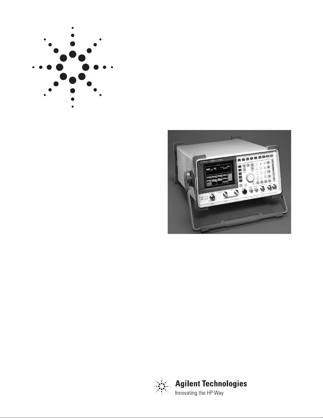
The Agilent Technologies 8920A RF communication
test set is a full-featured, one-box test set designed
to meet the service and repair needs of today’s RF
wireless communications market.
Single keystroke transmitter and receiver testing
simplifies radio test. Signaling for multiple formats
is supported, including tone sequential, digital paging (CCITT, POCSAG, ZVEI, etc.), DTMF, trunking,
and cellular signaling.
For cellular phone test, the call processing interface emulates a base station, allowing you to automatically establish and maintain a cellular link
between the test set and an analog cellular phone.
The built-in controller allows you to automate
measurements and test routines, and control external instruments. Combined with the Agilent 11807A
software, it provides a self-contained, automated
radio test solution.
Key Features:
• Intuitive call processing interface for cellular
phone test
• Functions of more than 20 complete instruments
• Frequency ranges:
Signal generator: 30 MHz to 1 GHz
RF analyzer: 10 MHz to 1 GHz
• Portable and lightweight
• Optional full-span spectrum analyzer, tracking
generator and adjacent channel power meter
• Built-in IBASIC computer
Agilent 8920A
RF Communications Test Set
Data Sheet
Page 2

2
Agilent 8920A RF Communications Test
Set Specifications
Specifications describe the instrument’s warranted performance
and are valid over the entire operating/environmental range
unless otherwise noted.
Supplemental Characteristics are intended to provide additional
information useful in applying the instrument by giving typical, but
non-warranted performance parameters. These characteristics are
shown in italics or labeled as “typical,” “usable to,” or “nominal.”
Signal Generator Specifications
RF Frequency
Frequency Range:
Standard: 30 MHz to 1 GHz
Option 055: 250 kHz to 1 GHz
Accuracy and Stability: Same as reference oscillator ±0.015 Hz
Reference Oscillator Specifications
TCXO (Agilent 8920A standard)
Temperature: 1 ppm (0 to +55 °C)
Aging: <2 ppm/year
Warm-Up time: <30 sec. to be ±2 ppm of final freq.
Supplemental Characteristics
Switching Speed: <150 ms to within 100 Hz of the carrier
frequency
Minimum Resolution: 1 Hz
Output
RF IN/OUT Connector
Level Accuracy: ±1.8 db (level ≥–127 dBm),
Typically ±1.0 dB for all levels
Level Range
Standard:
Level Range: –137 to –20.5 dBm into 50 Ω
Reverse Power: 60 watts continuous,
100 watts for 10 seconds/minute
With Option 007:
Level Range: –137 to –6.5 dBm into 50 Ω
Reverse Power: 2.4 watts continuous,
4 watts for 10 seconds/minute
With Option 008:
Level Range: –137 to –10.5 dBm into 50 Ω
Reverse Power: 6 watts continuous,
10 watts for 10 seconds/minute
With Option 016:
Level Range: –137 to –22.5 dBm into 50 Ω
Reverse Power: 100 watts continuous,
125 watts for 10 seconds/minute
Option 055:
Level Range: –137 to –19 dBm into 50 Ω
Reverse Power: 60 watts continuous,
100 watts for 10 seconds/minute
With Option 007:
Level Range: –137 to –5 dBm into 50 Ω
Reverse Power: 2.4 watts continuous,
4 watts for 10 seconds/minute
With Option 008:
Level Range: –137 to –9 dBm into 50 Ω
Reverse Power: 6 watts continuous,
10 watts for 10 seconds/minute
With Option 016:
Level Range: –137 to –21 dBm into 50 Ω
Reverse Power: 100 watts continuous,
125 watts for 10 seconds/minute
DUPLEX OUT Connector
Standard:
Level Accuracy: ±1.5 dB, typically ±1.0 dB for all levels
Level Range: –127 to +5 dBm into 50 Ω
Reverse Power: 200 mW max
Option 055:
Level Range: –127 to +7 dBm into 50 Ω
SWR:
RF In/Out: <1.5:1
Duplex Out: <2.0:1 (level <–4 dBm)
Supplemental Characteristics
Minimum Resolution: 0.1 dB
Spectral Purity
Spurious Signals: For specified output levels at DUPLEX OUT port
or specified output level at RF IN/OUT port.
Option DUPLEX OUT RF IN/OUT
Standard ≤–2.5 dBm ≤–26.5 dBm
007 ≤–2.5 dBm ≤–12.5 dBm
007 with Opt. 055 ≤–1.0 dBm ≤–11.0 dBm
008 ≤–2.5 dBm ≤–16.5 dBm
008 with Opt. 055 ≤–1.0 dBm ≤–15.0 dBm
016 ≤–2.5 dBm ≤–28.5 dBm
016 with Opt. 055 ≤–1.0 dBm ≤–27.0 dBm
055 ≤–1.0 dBm ≤–25.0 dBm
Harmonics: <–30 dBc
Non-Harmonic Spurious: <–60 dBc (at >5 kHz from carrier)
Residual FM (rms, CCITT):
Frequency Range 8920A Standard 8920A Opt. 050
250 kHz ≤f
c
<249 MHz <20 Hz <7 Hz
249 MHz ≤f
c
<501 MHz <10 Hz <4 Hz
501 MHz ≤fc≤1000 MHz <20 Hz <7 Hz
Page 3

3
Supplemental Characteristics
SSB Phase Noise: (For >20 kHz offsets at 1 GHz)
8920A <–110 dBc/Hz
8920A Opt. 050 <–116 dBc/Hz
FM
FM Deviation Maximum (For rates >25 Hz)
Standard and Options 007, 008, 016:
100 kHz for f
c
from 30 MHz to <249 MHz
50 kHz for f
c
from 249 MHz to <501 MHz
100 kHz for f
c
from 501 MHz to 1000 MHz
Option 055:
100 kHz for f
c
from 0.25 MHz to <249 MHz
50 kHz for f
c
from 249 MHz to <501 MHz
100 kHz for f
c
from 501 MHz to 1000 MHz
FM Rate (1 kHz reference)
Internal: DC to 25 kHz (1 dB BW)
External:
AC Coupled: 20 Hz to 75 kHz (typically 3 dB BW)
DC Coupled: DC to 75 kHz (typically 3 dB BW)
FM Accuracy: (1 kHz rate)
≤10 kHz dev: ±7.5% (3.5%*) of setting ±50 Hz
>10 kHz dev: ±7.5% (3.5%*) of setting ±500 Hz
FM Distortion: (THD + Noise, in a 0.3 to 3 kHz BW)
<1% (0.5 %*) at > 4 kHz deviation and 1 kHz rate
Center Frequency Accuracy in DC FM Mode:
(External source impedance <1 kΩ) ± 500 Hz
(after DC FM zero), typically ±50 Hz
Supplemental Characteristics
External Modulation Input Impedance: 600 Ω nominal
Resolution: 50 Hz for <10 kHz deviation, 500 Hz for >10 kHz
deviation
AM
Standard:
Frequency Range: 30 MHz to 1 GHz
AM Depth: 0 to 90% (usable to 99%) for DUPLEX OUT level
≤–2.5 dBm or RF IN/OUT level ≤–26.5 dBm; 0 to 70% (usable
to 90%*)
Option 055:
Frequency Range: 1.5 MHz to 1 GHz (usable to 250 kHz)
AM Depth: 0 to 90% (usable to 99%) for DUPLEX OUT level
≤+1 dBm or RF IN/OUT level ≤–27 dBm; 0 to 70% (usable to
90%*)
AM Rate: 20 Hz to 25 kHz (3 dB BW)
AM Accuracy: (1 kHz rate)
≤10% AM: ±5% of setting ±1.0% AM
>10% AM: ±5% of setting ±1.5% AM
AM Distortion: (THD+Noise 0.3 to 3 kHz BW)
<2% at 1 kHz rate, <30% AM
<3% at 1 kHz rate, ≤90% AM
Supplemental Characteristics
External Mod. Input Impedance: 600 Ω nominal
Residual AM: <0.1% in a 50 Hz to 15 kHz BW
Resolution: 0.05% AM from 0 to 10% AM, 0.5% AM from 10 to
100% AM
Audio Source Specifications
(Applicable to both internal sources)
Frequency
Range: dc to 25 kHz
Accuracy: 0.025% of setting
Supplemental Characteristics
Minimum Resolution: 0.1 Hz
Output Level
Range: 0.1 mV to 4 Vrms
Maximum Output Current: 20 mA peak
Output Impedance: <1 Ω (1 kHz)
Accuracy: ±2% of setting plus resolution
Residual Distortion: 0.125%
(THD plus noise, for amplitudes >200 mVrms), for tones 20 Hz to
25 kHz measured in an 80 kHz BW
Supplemental Characteristics
Resolution: Level <0.01V: ±50 µV
Level <0.1V: ±0.5 mV
Level <1V: ±5 mV
Level <10V: ±50 mV
Offset in DC Coupled Mode: <50 mV
RF Analyzer Measurements
RF Frequency Measurements
Measurement Range:
Standard: 30 MHz to 1 GHz
Option 055: 400 kHz to 1 GHz
Level Range:
RF In/Out:
Standard: 1 mW to 60 W continuous 100 W for
10 seconds/minute
Option 007: 40 mW to 6 W continuous 4 W for
10 seconds/minute
Option 008: 0.1 mW to 6 W continuous 10 W for
10 seconds/minute
Option 016: 1.6 mW to 100 W continuous 150 W for
10 seconds/minute
ANT IN: –36 dBm to +20 dBm
Accuracy: ±1 Hz plus timebase accuracy
Page 4

4
Supplemental Characteristics
Minimum Frequency Resolution: 1 Hz
RF Power Measurements
Frequency Range:
Standard: 30 MHz to 1 GHz
Option 055: 400 kHz to 1 GHz
SWR: <1.5:1 for standard and all options
RF IN/OUT Measurement Range:
Standard: 1 mW to 60 W continuous or to 100 W for
10 sec/minute
Accuracy: ±10% of reading ±1 mW
Option 007: 40 µW to 2.4 W continuous 4 W for
10 seconds/minute
Accuracy: ±10% of reading ±40 µW
Option 008: 0.1 mW to 6 W continuous 10 W for
10 seconds/minute
Accuracy: ±10% of reading ±0.1 mW
Option 016: 1.6 mW to 100 W continuous 125 W for
10 seconds/minute
Accuracy: ±10% of reading ±1 mW
Supplemental Characteristics
Resolution: P >10 W: 10 mW, P <10 W: 1 mW; P <100 mW: 0.1
mW, P <10 mW: 0.01 mW
FM Measurement
Frequency Range:
Standard: 10 MHz to 1 GHz
Option 055: 5 MHz to 1 GHz (Usable to 400 kHz)
Deviation: 20 Hz to 75 kHz
Sensitivity: 2 µV (15 kHz IF BW, high sensitivity mode, 0.3 to 3 kHz
BW, 12 SINAD, fc >10 MHz) Typically: <1 µV
Accuracy: ±4% of reading plus residual FM and noise contribution
(20 Hz to 25 kHz rates, deviation ≤25 kHz)
Bandwidth (3 dB): 2 Hz to 70 kHz (DC FM measurements also
available)
Input Level Range for Specified Accuracy:
Standard: –50 dBm to +14 dBm at ANT IN –18 to +50 dBm at
RF IN/OUT (0.16 mW to 100 W*)
Option 007: –32 to +36 dBm at RF IN/OUT (0.63 µW to 4 W*)
Option 008: –28 to +40 dBm at RF IN/OUT (1.58 µW to 10 W*)
Option 016: –16 to +51 dBm at RF IN/OUT (0.25 µW to 125 W*)
*Note: The accuracy shown is for the complete range of power.
The maximum power levels shown are only usable for 10
sec/min.
Residual FM and Noise: 20 Hz (0.3 to 3 kHz, rms), <7 Hz (with
Agilent 8920A Opt 050)
Supplemental Characteristics
Resolution: 1 Hz, f <10 kHz; 10 Hz, f ≥10 kHz
AM Measurement
Frequency Range: 10 MHz to 1 GHz (usable to 400 kHz)
Depth: 0 to 95%
Accuracy: ±5% of reading ±1.5% AM (50 Hz to 10 kHz rates, mod-
ulation ≤ 80%)
THD + Noise: <2% rms for modulation ≤80% AM (at 1 kHz rate in
a 0.3 to 3 kHz BW)
Input Level Range for Specified Accuracy:
Standard: –50 dBm to +14 dBm at ANT IN –18 to +50 dBm at
RF IN/OUT (0.16 mW to 100 W*)
Option 007: –32 to +36 dBm at RF IN/OUT (0.63 µW to 4 W*)
Option 008: –28 to +40 dBm at RF IN/OUT (1.58 µW to 10 W*)
Option 016: –16 to +51 dBm at RF IN/OUT (0.25 µW to 125 W*)
*Note: The accuracy shown is for the complete range of power.
The maximum power levels shown are only usable for 10 sec/min.
Residual AM: <0.2% in a 0.3 to 3 kHz bw
Supplemental Characteristics
Resolution: 0.1%
SSB Measurement
Frequency Range:
Standard: 10 MHz to 1 GHz
Option 055: 400 kHz to 1 GHz
Bandwidth (3 dB): 20 Hz to 70 Hz
Distortion and Noise: <3% (at 1 kHz rate in a 0.3 to 3 kHz BW)
AF Analyzer Specifications
Frequency Measurement
Measurement Range: 20 Hz to 400 kHz
Accuracy: ±0.02% plus resolution plus timebase accuracy
External Input: 20 mV to 30 Vrms
Supplemental Characteristics
Resolution: 0.01 Hz, f <10 kHz; 0.1 Hz, f <100 kHz; and 1 Hz for
f ≥100 kHz
AC Voltage Measurement
Measurement Range: 0 to 30 Vrms
Accuracy: ±3% of reading (20 Hz to 15 kHz, inputs >1 mV)
Residual Noise: 150 µV (15 kHz bandwidth)
Page 5

5
Supplemental Characteristics
3 dB Bandwidth: Typically 2 Hz to 100 kHz
Nominal Input Impedance: Switchable between
1 MW in parallel with 95 pF or 600 Ω floating
Minimum Resolution: 4 digits for inputs ≥100 mV; three digits for
inputs <100 mV
DC Voltage Measurement
Voltage Range: 100 mV to 42 V
Accuracy: ±1% of reading plus DC offset
DC Offset: ±45 mV
Supplemental Characteristics
Resolution: 1 mV
Distortion Measurement
Fundamental Frequency: 1 kHz ±5 Hz
Option 019 Frequency Range: 0.3 to 10 kHz ±5%
Input Level Range: 30 mV to 30 Vrms
Display Range: 0.1% to 100%
Accuracy:
±1 dB (0.5 to 100% distortion) for tones from 300 to 1500 Hz
measured with the 15 kHz LPF
±1.5 dB (1.5 to 100% distortion) for tones from 300 Hz to 10 kHz
measured with the >99 kHz LPF)
Residual THD + Noise:
–60 dBc or 150 µV whichever is greater, for tones from 300 to
1500 Hz measured with the 15 kHz LPF
–57 dBc or 450 µV, whichever is greater, for tones from 300 Hz to
10 kHz measured with >99 kHz LPF)
Supplemental Characteristics
Resolution: 0.1% distortion
SINAD Measurement
Fundamental Frequency: 1 kHz ±5 Hz
Option 019 Frequency Range: 0.3 to 10 kHz ±5%
Input Level Range: 30 mV to 30 Vrms
Display Range: 0 to 60 dB
Accuracy:
±1 dB (0 to 46 dB SINAD) for tones from 300 to 1500 Hz measured
with the 15 kHz LPF
±1.5 dB (0 to 36 dB SINAD) for tones from 300 Hz to 10 kHz measured with the >99 kHz LPF
Residual THD + Noise:
–60 dBc or 150 mV, whichever is greater, for tones from 300 to
1500 Hz measured with the 15 kHz LPF
–57 dBc or 450 mV, whichever is greater, for tones from 300 Hz to
10 kHz measured with >99 kHz LPF
Supplemental Characteristics
Resolution: 0.01 dB
Audio Filters
Standard: <20 Hz HPF, 50 Hz HPF, 300 Hz HPF 300 Hz LPF, 3 kHz LPF,
15 kHz LPF, >99 kHz LPF, and 750 µsec de-emphasis
Fixed Notch: 1 kHz, (Agilent 8920A standard)
Variable Notch: 300 Hz to 10 kHz (Option 019)
Optional: C-Message, CCITT, 400 Hz HPF, 4 kHz BPF, 6 kHz BPF
(see options)
Audio Detectors: RMS, RMSxSQRT2, Pk+, Pk–, Pk+hold, Pk–hold,
Pk±/2, Pk±/2 hold, Pk±max and Pk±max hold
Oscilloscope Specifications
Frequency Range: 2 Hz to 50 kHz (3 dB BW)
Scale/Division: 10 mV to 10 V
Amplitude Accuracy: ±1.5% of reading ±0.1 division
(20 Hz to 10 kHz)
Time/Division: 1 µsec to 200 msec
Supplemental Characteristics
3 dB Bandwidth: Typically >100 kHz
Internal DC Offset: ≤0.1 div (≥50 µV/div sensitivity)
Input and Output Specifications
Digital Interface Port
RS-232 port: 2 way
Connector: RJ-11 connector (6 pins; 2 addressable serial ports
with single connector; Agilent 8920A rear panel)
Baud Rates: 300/600/1200/2400/4800/9600/19200
Reference In Port
Connector: BNC female (8920A rear panel)
Input frequency: 1/2/5/10 MHz
Input Level Range: >0.15 Vrms
Reference Out Port
Connector: BNC female (8920A rear panel)
Output Frequency: 10 MHz
Output Level: >0.5 Vrms
Standard User Memory, RAM
Approximately 1 Mbyte of RAM is available for nonvolatile
save/recall of settings. This typically will allow you to save >1000
sets of instrument settings; depending on the type of information
saved.
Page 6

6
Option Specifications
Option 001: High Stability Timebase
OCXO: (Oven controlled crystal oscillator)
Temperature: 0.05 ppm (0 to +55 °C)
Aging: <0.5 pm/year (<1 ppm in first year)
Warm-up Time: <15 minutes to be within ±0.1 ppm of final
frequency
Supplemental Characteristics
Rear Panel BNC Connectors:
Input Frequency: 1, 2, 5, and 10 MHz
Input Level: >0.15 Vrms
Output Frequency: 10 MHz
Output Level: >0.5 Vrms
Option 004: Tone/Digital Signalling
Capability for generating and analyzing the formats listed here:
CDCSS, DTMF, 1-TONE, 2-TONE, 5/6 TONE SEQUENTIAL, RPC1,
POCSAG, EIA, CCITT, CCIR, ZVEI, DZVEI, GOLAY, EEA, NMT-450,
NMT-900, LTR, AMPS/EAMPS/NAMPS, TACS/ETACS,
JTACS/NTACS, EDACS, and MPT 1327.
A General Purpose function generator with the following wave
forms included: Sine, square, triangle, ramp, Gaussian white
noise, uniform white noise
Frequency Range/Level: Same as audio source
Option 007 and Low-Level RF Power
Measurements
Option 007 removes a 14 dB attenuator at the RF IN/OUT port
allowing lower-level, higher sensitivity measurements. This option
reduces the maximum continuous input power of the Agilent
8920A from 60 watts to 2.4 watts. Specifications for Option 007
are included in the appropriate sections of: Signal Generator output, RF Analyzer, Frequency and Power Measurement Ranges, FM
and AM Measurement Input Level Ranges.
Option 008 Cellular Mobile RF Power
Measurement Range
Option 008 removes 10 dB attenuation at the RF IN/OUT port
allowing lower-level, higher sensitivity measurements specifically
for the range of cellular telephones testing. This option reduces
the maximum continuous input power of the 8920A from 60 watts
to 6 watts. Specifications for Option 008 are included in the appropriate sections of: Signal generator output, RF analyzer, frequency
and power measurement ranges, FM and AM measurement input
level ranges.
Option 010: 400 Hz High Pass Filter
Option 011: CCITT Weighting Filter
Option 012: 4 kHz Bandpass Filter
Option 013: C-Message Weighted Filter
Option 014: 6 kHz Bandpass Filter
Option 016 High-Level RF Power Measurements
Option 016 for the 8920A supports high-power transmitter measurement applications. Option 016 can only be ordered on a new
instrument at the time of purchase. Option 016 can only be
installed at the factory.
Option 019: Variable Notch Filter
Frequency Range: 300 Hz to 10 kHz
Notch Depth: >60 dB
Notch Width: Typically ±5%
Option 020: Radio Interface Card
The Option 020 for the 8920A is a built-in radio interface card for
automating module and radio board test. It contains 16 parallel
data lines, two interrupts, and brings the audio in/out lines and a
relay closure out from the MIC/ACC connector on the front panel.
These are controlled by the 8920A BASIC control language.
Line Levels: 5 volts or 12 volts
Option 050: Improved Residual FM Performance
Includes high stability timebase (Option 001), improved residual
FM performance.
Option 102: Spectrum Analyzer with Tracking
Generator and ACP
Frequency Range: 10 MHz to 1 GHz
Frequency Span/Resolution Bandwidth: (coupled)
Span Bandwidth
<50 kHz 300 Hz
<200 kHz 1 kHz
<1.5 MHz 3 kHz
<18 MHz 30 kHz
>18 MHz 300 kHz, plus full span capability
Display: Log with 1, 2, and 10 dB/div
Display Range: 80 dB
Reference Level Range: +50 to –50 dBm
Residual Responses: <–70 dBm (no input signal, 0 dB
attenuation)
Image Rejection: >50 dBm
Supplemental Characteristics
Non-Harmonic Spurious Responses: >70 dB down (for input sig-
nals ≤–30 dBm)
Page 7

7
Level Accuracy: ±2.5 dB
Displayed Average Noise Level: <–114 dBm for <50 kHz spans
Log Scale Linearity: ±2 dB (for input levels ≤–30 dBm and/or
60 dB range
Tracking Generator (In Option 102)
Frequency Range: 30 MHz to 1 GHz
Frequency Offset: Frequency span endpoints ± frequency offset
cannot be <30 MHz or ≥1 GHz
Output Level Range: Same as signal generator
Sweep Modes: Normal and inverted
Adjacent Channel Power (In Option 102)
Relative Measurements:
Level Range:
Antenna IN: –40 dBm to +20 dBm
RF/Input: 0.16 mW (–8 dBm) to 60 W (47.8 dBm)
continuous; or up to 100 mW (50 dBm) for 10 sec/min
Dynamic Range: Typical values for channel offsets
Channel Offset Res. BW Dyn. Range
12.5 kHz 8.5 kHz –65 dBc
20 kHz 14 kHz –68 dBc
25 kHz 16 kHz –68 dBc
30 kHz 16 kHz –68 dBc
60 kHz 30 kHz –65 dBc
Relative Accuracy: ±2 dB
Absolute Level Measurements:
Level: (Results of absolute power in watts or dBm are met by
adding the ACP ratio from the SA to the carrier power from the
input section RF power detector).
Level Range:
Antenna: N/A
RF/Input: 1 mW (0 dBm) to 60 W (47.8 dBm) continuous; or
up to 100 W (50 dBm) for 10 sec/min
Dynamic Range: Typical values for channel offsets
Channel Offset Res. BW Dyn. Range
12.5 kHz 8.5 kHz –65 dBc
20 kHz 14 kHz –68 dBc
25 kHz 16 kHz –68 dBc
30 kHz 16 kHz –68 dBc
60 kHz 30 kHz –65 dBc
Absolute Accuracy: RF power measurement accuracy found in
the RF Analyzer section and ACP relative accuracy of ±2 dB
Option 103: DC Current Sensing and I/O:
GPIB/RS-232/Parallel (Centronics)
DC Current Meter
Measurement Range: 0 to 10 A (usable to 20 A)
Accuracy: The greater of ±10% of reading after zeroing or 30 mA
(levels >100 mA)
Remote Programming
GPIB: Agilent’s implementation of IEEE Standard 488.2
Functions Implemented: SH1, AH1, T6, L4, SR1, RL1, LE0, TE0,
PP0, DC1, DT1, C4, C11, E2
RS-232: Two serial ports through RJ-11 connector used for serial
data in and out
Baud Rates: 150, 300, 600, 1200, 2400, 4800, 9600 and 19200 Hz
Parallel (Centronics) Connector: A standard 25-pin, sub-min D
female connector with right-angle adapter is included
Note: Retrofittable only for 8920A units with serial prefix numbers
of 3501 or greater
General Specifications
8920A Dimensions: H 3 W 3 D in inches and (mm): 7.5 H 3 13 W
3 19 D (188 H 3 330 W 3 456 D)
8920A Weight: (fully optioned) 37 lbs. (16.8 kgs)
8920A Power:
AC: 100 V to 240 V, 48 to 440 Hz, nominally 80 watts
DC: 11 to 28 V, nominally 120 watts
8920D Power:
AC: 100 V to 240 V ±10%, 48 Hz to 440 Hz, nominally 100 watts
CRT Size: 7 3 10 cm
Operating Temperature: 0 to +55 °C
Storage Temperature: –55 to +75 °C
Calibration Interval: Two years
Supplemental Characteristics
Leakage: At signal generator output frequency and level <–40 dBm,
typical leakage is <0.5 µV induced in a resonant dipole antenna
one inch from any surface except the rear panel. Spurious leakage
levels are typically <1 µV in a resonant dipole antenna.
Page 8

High Stability Timebase
Signaling
Low-Power Measurement
Cellular MS RF Power Range
400 Hz High-Pass Filter
CCITT Weighting Filter
4 kHz Bandpass Filter
C-Message Weighting Filter
6 kHz Bandpass Filter
Variable Frequency Filter
Mechanical Attenuator
Specrum Analy./Tracking Gen
GPIB/RS-232 Parallel
11807A Radio Test Software (Options)
Automated FM Radio Test
3
O O O O O O 001
Automated φm Radio Test
3
O O O O O 002
Automated AM Radio Test O O 003
Testing Communications
Bandwidths <30 MHz X
Cordless Phone Test
3
O O X O
Frequency Scanning O
Cable Fault Location
2
X O
Field Strength Measurement X O 100
Intermodulation Prod. Cal. O
Save/Recall Procedure O
LTR Trunked Radio Test
3
(Includes FM radio tests) O X X O O O 010
EDACS Trunked Radio Test
3
(Includes FM radio tests) O X O O O O 011
MPT 1327 Trunked Radio Test
3
O X O O O O 012
AMPS/EAMPS/NAMPS O X O O O O 004
TACS/ETACS O X O O O O 005
NMT 450/900 O X O O O O 006
JTACS/NTACS O X O O O 007
Configuration Information X = Required Option O = Recommended Option
8920A Options 001 004 00710081010 011 012 013 014 019 055 102 103
Measuring CapabilityTrunked RadioCellular Phone Test
1. Options 007 and 008 reduce the maximum input power of the 8920A from
60 watts to 2.4 and 6 watts respectively. Option 008 is recommended for
applications where the 8920A is used for cellular phone test only.
2. Requires an external power divider and 50 ohm load to make measurement.
3. Testing frequencies below 30 MHz will require ordering Option 055 (400 kHz
to 1 GHz).
By internet, phone, or fax, get assistance with all your
test and measurement needs.
Online Assistance
www.agilent.com/find/assist
Product specifications and descriptions in this
document subject to change without notice.
Copyright © 1994, 2000 Agilent Technologies
Printed in U.S.A. 10/00
5968-5385E
For more information, visit our website at:
www.agilent.com/find/8920support/
 Loading...