

Page 1

Service Guide
Agilent Technologies
8752C
Network Analyzer
Manufacturing Part Number: 08752-90136
Printed in USA
Print Date: February 1998
Supersedes: December 1997
© Agilent Technologies, Inc. 1998
Page 2

Hewlett-Packard to Agilent Technologies Transition
This manual may contain references to HP or Hewlett-Packard. Please note that
Hewlett-Packard's former test and measurement, semiconductor products and chemical analysis
businesses are now part of Agilent Technologies. To reduce potential confusion, the only
change to product numbers and names has been in the company name prefix: where a product
number/name was HP XXXX the current name/number is now Agilent XXXX. For example,
model number HP 8752C is now model number Agilent 8752C.
Documentation Warranty
THE MATERIAL CONTAINED IN THIS DOCUMENT IS PROVIDED "AS IS," AND IS
SUBJECT TO BEING CHANGED, WITHOUT NOTICE, IN FUTURE EDITIONS. FURTHER, TO THE MAXIMUM EXTENT PERMITTED BY APPLICABLE LAW, AGILENT
DISCLAIMS ALL WARRANTIES, EITHER EXPRESS OR IMPLIED WITH REGARD TO
THIS MANUAL AND ANY INFORMATION CONTAINED HEREIN, INCLUDING BUT
NOT LIMITED TO THE IMPLIED WARRANTIES OF MERCHANTABILITY AND FITNESS FOR A PARTICULAR PURPOSE. AGILENT SHALL NOT BE LIABLE FOR
ERRORS OR FOR INCIDENTAL OR CONSEQUENTIAL DAMAGES IN CONNECTION
WITH THE FURNISHING, USE, OR PERFORMANCE OF THIS DOCUMENT OR ANY
INFORMATION CONTAINED HEREIN. SHOULD AGILENT AND THE USER HAVE A
SEPARATE WRITTEN AGREEMENT WITH WARRANTY TERMS COVERING THE
MATERIAL IN THIS DOCUMENT THAT CONFLICT WITH THESE TERMS, THE WARRANTY TERMS IN THE SEPARATE AGREEMENT WILL CONTROL.
DFARS/Restricted Rights Notice
If software is for use in the per formance of a U.S. Government prime contract or
subcontract, Software is delivered and licensed as “Commercial computer software” as
defined in DFAR 252.227-7014 (June 1995), or as a “commercial item” as defined in FAR
2.101(a) or as “Restricted computer sof tware” as defined in FAR 52.227-19 (June 1987) or
any equivalent agency regulation or contract clause. Use, duplication or disclosure of
Software is subject to Agilent Technologies’ standard commercial l icense terms, and
non-DOD Departments and Agencies of the U.S. Government will receive no greater than
Restricted Rights as defined in FAR 52.227-19(c)(1-2) (June 1987) . U.S. Government users
will receive no greater than Limited Rights as defined in FAR 52.227-14 (June 1987) or
DFAR 252.227-7015 (b)(2) (November 1995), as applicable in any technical data.
Page 3

Printing Copies of Documentation from the Web
To print copies of documentation from the Web, download the PDF file from the Agilent
web site:
•Go to http://www.agilent.com.
• Enter the document’s pa rt number (located on the title page) in the Quick Search box.
• Click GO.
• Click on the hyperlink for the document.
• Click the printer icon located in the tool bar.
Page 4

Contacting Agilent
This information supersedes all prior HP contact information.
Online assistance: www.agilent.com/find/assist
Americas
Brazil
(tel) (+55) 11 3351 7012
(fax) (+55) 11 3351 7024
Canada
(tel) +1 877 894 4414
(fax) +1 303 662 3369
Mexico
(tel) 1 800 254 2440
(fax) 1 800 254 4222
Asia Pacific and Japan
Australia
(tel) 1 800 225 574
(fax) 1 800 681 776
(fax) 1 800 225 539
Japan (Bench)
(tel) 0120 32 0119
(alt) (+81) 426 56 7799
(fax) 0120 01 2144
Taiwan
(tel) 0800 047 669
(fax) 0800 047 667
(fax) 886 3492 0779
China
(tel) 800 810 0508
(alt) 800 810 0510
(fax) 800 810 0507
(fax) 800 810 0362
Japan (On-Site)
(tel) 0120 802 363
(alt) (+81) 426 56 7498
(fax) (+81) 426 60 895 3
Thailand
(tel) 1 800 2758 5822
(alt) (+66) 2267 5913
(fax) 1 800 656 336
Hong Kong
(tel) 800 933 229
(fax) 800 900 701
Singapore
(tel) 1 800 275 0880
(fax) (+65) 675 5 1235
(fax) (+65) 675 5 1214
Malaysia
(tel) 1800 880 399
(fax) 1800 801 054
Europe
Austria
(tel) 0820 87 44 11*
(fax) 0820 87 44 22
France
(tel) 0825 010 700*
(alt) (+33) (0)1 6453 5623
(fax) 0825 010 701*
Italy
(tel) (+39) (0)2 9260 8484
(fax) (+39) (0)2 9544 1175
Spain
(tel) (+34) 91 631 3300
(alt) (+34) 91 631 3000
(fax) (+34) 91 631 3301
Switzerland (Italian)
(tel) 0800 80 5353 opt. 3*
(alt) (+39) (0)2 9260 8484
(fax) (+41) (0)22 567 5314
(tel) = primary telephone number; (alt) = alternate telephone number; (fax) = FAX number; * = in country number
11/16/04
Belgium
(tel) (+32) (0)2 404 9340
(alt) (+32) (0)2 404 9000
(fax) (+32) (0)2 404 9395
Germany
(tel) 01805 24 6333*
(alt) 01805 24 6330*
(fax) 01805 24 6336*
Luxemburg
(tel) (+32) (0)2 404 9340
(alt) (+32) (0)2 404 9000
(fax) (+32) (0)2 404 9395
Sweden
(tel) 0200 88 22 55*
(alt) (+46) (0)8 5064 8686
(fax) 020 120 2266*
United King dom
(tel) (+44) (0)7004 666666
(alt) (+44) (0)7004 123123
(fax) (+44) (0)7004 444555
Denmark
(tel) (+45) 7013 1515
(alt) (+45) 7013 7313
(fax) (+45) 701 3 1555
Ireland
(tel) (+353) (0)1 890 924 204
(alt) (+353) (0)1 890 924 206
(fax)(+353) (0 )1 890 924 024
Netherlands
(tel) (+31) (0)20 547 2111
(alt) (+31) (0)20 547 2000
(fax) (+31) (0)20 547 2190
Switzerland (French)
(tel) 0800 80 5353 opt. 2*
(alt) (+33) (0)1 6453 5623
(fax) (+41) (0)22 567 5313
United States
(tel) 800 829 4444
(alt) (+1) 303 662 3998
(fax) 800 829 4433
India
(tel) 1600 112 626
(fax) 1600 112 727
(fax) 1600 113 040
South Korea
(tel) 080 778 0011
(fax) 080 778 0013
Finland
(tel) (+358) 10 855 2100
(fax) (+358) (0) 10 855 2923
Israel
(tel) (+972) 3 9288 500
(fax) (+972) 3 9288 501
Russia
(tel) (+7) 095 797 3963
(alt) (+7) 095 797 3900
(fax) (+7) 095 797 3901
Switzerland (German )
(tel) 0800 80 5353 opt. 1*
(alt) (+49) (0)7031 464 63 33
(fax) (+41) (0)1 272 7373
Page 5

Service Guide
HP 8752C Network Analyzer
ABCDE
HP Part No. 08752-90136 Supersedes December 1997
Printed in USA February 1998
Page 6

Notice.
The information contained in this document is subject to change without notice.
Hewlett-Packard makes no warranty of any kind with regard to this material,
including but not limited to, the implied warranties of merchantability and
tness for a particular purpose. Hewlett-Packard shall not be liable for errors
contained herein or for incidental or consequential damages in connection with
the furnishing, performance, or use of this material.
c
Copyright 1995, 1997, 1998 Hewlett-Packard Company
Page 7
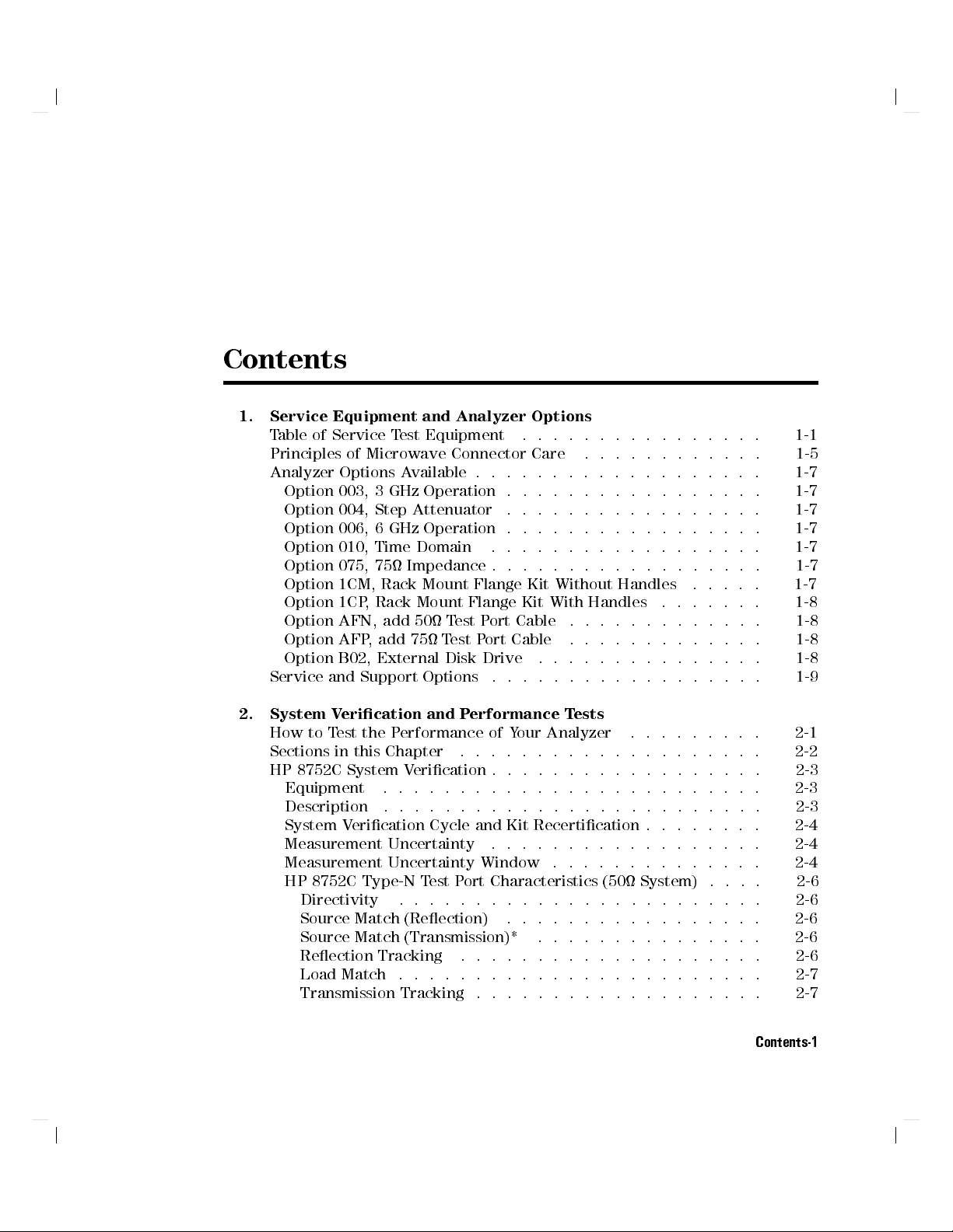
Contents
1. Service Equipment and Analyzer Options
Table of Service Test Equipment ................ 1-1
Principles of Microwave Connector Care ............ 1-5
Analyzer Options Available . . . . . . . . . . . . . . . . . . .
Option 003, 3 GHz Operation . . . . . . . . . . . . . . . . .
Option 004, Step Attenuator .................
Option 006, 6 GHz Operation . . . . . . . . . . . . . . . . .
Option 010, Time Domain ...... ...... ......
Option 075, 75 Impedance . . . . . . . . . . . . . . . . . .
Option 1CM, Rack Mount Flange Kit Without Handles .. ... 1-7
Option 1CP, Rack Mount Flange Kit With Handles ....... 1-8
Option AFN, add 50 Test Port Cable .............
Option AFP, add 75 Test Port Cable .... ...... ...
Option B02, External Disk Drive ...... ...... ...
Service and Support Options ..................
2. System Verication and Performance Tests
How to Test the Performance of Your Analyzer .... .....
Sections in this Chapter ....................
HP 8752C System Verication . . . . . . . . . . . . . . . . . . 2-3
Equipment ......................... 2-3
Description .... ...... ...... ...... ... 2-3
System Verication Cycle and Kit Recertication . . . . . . . . 2-4
Measurement Uncertainty ...... ...... ......
Measurement Uncertainty Window ..............
HP 8752C Type-N Test Port Characteristics (50 System) .... 2-6
Directivity ........................
Source Match (Reection) ...... ...... .....
Source Match (Transmission)* ............... 2-6
Reection Tracking ....................
Load Match ........................
Transmission Tracking . . . . . . . . . . . . . . . . . . . 2-7
1-7
1-7
1-7
1-7
1-7
1-7
1-8
1-8
1-8
1-9
2-1
2-2
2-4
2-4
2-6
2-6
2-6
2-7
Contents-1
Page 8
HP 8752C Type-N Test Port Characteristics (75 System) .... 2-7
Directivity ........................ 2-7
Source Match (Reection) ................. 2-7
Source Match (Transmission)* .. ...... ....... 2-8
Reection Tracking .... ...... ...... .... 2-8
Load Match ........................ 2-8
Transmission Tracking ...... ...... ...... . 2-8
System Verication Procedure ...... ...... ..... 2-9
In case of diculty ..................... 2-10
HP 8752C Performance Tests . . . . . . . . . . . . . . . . . . 2-11
Equipment Required to Run the Performance Tests ...... 2-12
1. Reection Test Port Output Frequency Range and Accuracy .. 2-13
Specications ........................
Equipment .. ...... ...... ...... .....
Description .........................
Procedure . . . . . . . . . . . . . . . . . . . . . . . . . .
In case of diculty .....................
2-13
2-13
2-13
2-14
2-14
2. Reection Test Port Output Power Range and Level Linearity
(For HP 8752C Analyzers without Option 004) ........ 2-15
Specications ........................
Equipment .. ...... ...... ...... .....
Description .........................
Procedure . . . . . . . . . . . . . . . . . . . . . . . . . .
2-15
2-15
2-15
2-16
Power Range and Level Linearity for an HP 8752C or an HP
8752C Option 075 ...................
2-16
Power Range and Level Linearity for an HP 8752C with Option
003 ..........................
2-17
Power Range and Level Linearity for an HP 8752C with Options
003 and 075 ...... ........ ...... .. 2-18
Power Range and Level Linearity for an HP 8752C with Option
006 .......................... 2-18
In case of diculty .. ...... ...... ...... 2-18
3. Reection Test Port Output Power Range and Level Linearity (HP
8752C with Option 004) . . . . . . . . . . . . . . . . . . .
Specications ........................
Equipment .. ...... ...... ...... .....
Description .........................
Procedure . . . . . . . . . . . . . . . . . . . . . . . . . .
2-19
2-19
2-19
2-19
2-20
Power Range for an HP 8752C with Option 004 ....... 2-20
Power Level Linearity for an HP 8752C with Option 004
or an HP 8752C withOptions 004 and 075 ........ 2-21
Contents-2
Page 9
Power Level Linearity for an HP 8752C with Options 003 and
004 .. ...... ...... ...... ...... 2-22
Power Level Linearity for an HP 8752C with Options 004 and
006 .. ...... ...... ...... ...... 2-23
Power Level Linearity for an HP 8752C with Options 003, 004,
and 075 .. ...... ...... ....... ... 2-23
In case of diculty .................... 2-23
4. Transmission Test Port Input Noise Floor Level (HP 8752C
without Option 075) .. ...... ...... ...... 2-24
Specications ........................ 2-24
Equipment ......................... 2-24
Description .... ...... ...... ...... ... 2-24
Procedure . . . . . . . . . . . . . . . . . . . . . . . . . .
Noise Floor Level at 300 kHz to 1.3 GHz (Standard Option), 300
kHz to 3 GHz (Option 003), or 300 kHz to 6 GHz (Option
006) with an IF BW of 3 kHz
...... ..... ...
Noise Floor Level at 300 kHz to 1.3 GHz (Standard Option) or
300 kHz to 3 GHz (Option 003) with an IF BW of 10 Hz . .
Noise Floor Level at 3 GHz to 6 GHz (Option 006) with an IF
BWof10Hz ...... ...... ........ ..
Noise Floor Level at 3 GHz to 6 GHz (Option 006) with IF BW of
3 kHz .........................
In case of diculty ....................
5. Transmission Test Port Input Noise Floor Level
(HP 8752C with Option 075) . . . . . . . . . . . . . . . . .
Specications ........................
Equipment .........................
Description .... ...... ...... ...... ...
Procedure . . . . . . . . . . . . . . . . . . . . . . . . . . 2-29
Noise Floor Level at 300 kHz to 1.3 GHz (Option 075) or 300
kHz to3 GHz (Options 075 and 003) with an IF BW of 3 kHz 2-29
Noise Floor Level at 300 kHz to 1.3 GHz (Option 075) or 300
kHz to3 GHz (Options 075 and 003) with an IF BW of 10 Hz 2-31
In case of diculty ....................
6. Test Port Crosstalk ........ ...... ...... .
Specications ........................
Equipment .........................
Description .... ...... ...... ...... ...
Procedure . . . . . . . . . . . . . . . . . . . . . . . . . .
Test Port Crosstalk for a Standard HP 8752C or an HP 8752C
with Option 003 ....................
2-24
2-24
2-26
2-27
2-28
2-28
2-29
2-29
2-29
2-29
2-31
2-32
2-32
2-32
2-32
2-33
2-33
Contents-3
Page 10
Test Port Crosstalk for an HP 8752C with Option 006 . . . . . 2-33
Test Port Crosstalk for an HP 8752C with Option 075 . . . . . 2-34
Test Port Crosstalk for an HP 8752C with Options 003 and 075 2-34
In case of diculty .. ...... ...... ...... 2-35
7. System Trace Noise . . . . . . . . . . . . . . . . . . . . . 2-36
Specications ........................ 2-36
Equipment .. ...... ...... ...... ..... 2-36
Description ......................... 2-36
Procedure . . . . . . . . . . . . . . . . . . . . . . . . . . 2-37
Reection Trace Noise (Magnitude) ............. 2-37
Reection Trace Noise (Phase) .. ...... ...... . 2-38
Transmission Trace Noise (Magnitude) . . . . . . . . . . . . 2-38
Transmission Trace Noise (Phase) . . . . . . . . . . . . . .
In case of diculty .. ...... ...... ......
2-39
2-39
8. Magnitude Dynamic Accuracy (HP 8752C - All Options) .... 2-40
Specications ........................
Equipment .. ...... ...... ...... .....
Description .........................
Procedure . . . . . . . . . . . . . . . . . . . . . . . . . .
In case of diculty .. ...... ...... ......
2-40
2-40
2-41
2-41
2-44
9. Phase Dynamic Accuracy (HP 8752C - All Options) ...... 2-45
Specications ........................
Equipment .. ...... ...... ...... .....
Description .........................
Procedure . . . . . . . . . . . . . . . . . . . . . . . . . .
10. Compression . . . . . . . . . . . . . . . . . . . . . . . .
Specications ........................
Equipment .. ...... ...... ...... .....
2-45
2-45
2-45
2-46
2-47
2-47
2-47
Description ......................... 2-47
Procedure . . . . . . . . . . . . . . . . . . . . . . . . . . 2-48
In case of diculty .. ...... ...... ...... 2-49
Performance Test Record . . . . . . . . . . . . . . . . . . . . 2-50
3. Adjustments and Correction Constants
When to Perform the Adjustment Procedures ..........
Keep Correction Constants Current to Save Time ....... 3-1
Adjustment Procedure Error Messages ...... ...... 3-1
Perform Adjustments in This Order .... ...... ..... 3-2
Test Equipment Specications ................ 3-3
Analyzer Cover Removal . . . . . . . . . . . . . . . . . . .
1. A9 CC Jumper Position Procedure .............. 3-5
Contents-4
3-1
3-4
Page 11

A9 CC (Correction Constant) Jumper Position ........ . 3-5
Procedure . . . . . . . . . . . . . . . . . . . . . . . . . . 3-5
2. Source Default Correction Constants (Test #44) ........ 3-8
Equipment ......................... 3-8
Warm-up time . . . . . . . . . . . . . . . . . . . . . . . 3-8
Description and Procedure . . . . . . . . . . . . . . . . . . 3-8
3. Source Pretune Default Correction Constants (Test #45) . . . . 3-9
Equipment ......................... 3-9
Warm-up time . . . . . . . . . . . . . . . . . . . . . . . 3-9
Description and Procedure . . . . . . . . . . . . . . . . . . 3-9
4. Analog Bus Correction Constants (Test #46) . . . . . . . . . . 3-10
Equipment ......................... 3-10
Warm-up time . . . . . . . . . . . . . . . . . . . . . . .
Description and Procedure . . . . . . . . . . . . . . . . . .
5. RF Output Power Correction Constants (Test #47) . . . . . . .
Equipment Required . . . . . . . . . . . . . . . . . . . . .
Warm-up time . . . . . . . . . . . . . . . . . . . . . . .
Description and Procedure . . . . . . . . . . . . . . . . . .
Power Sensor Calibration Factor Entry .. ...... ....
Source Correction Routine .... ...... ...... ..
6. Source Pretune Correction Constants (Test #48) . . . . . . . .
Equipment Required . . . . . . . . . . . . . . . . . . . . .
Warm-up time . . . . . . . . . . . . . . . . . . . . . . .
Description and Procedure . . . . . . . . . . . . . . . . . .
7. Display Intensity Adjustments (Test #49) ...........
Equipment Required . . . . . . . . . . . . . . . . . . . . .
Warm-up time . . . . . . . . . . . . . . . . . . . . . . .
Description and Procedure . . . . . . . . . . . . . . . . . .
3-10
3-10
3-11
3-11
3-11
3-11
3-12
3-13
3-14
3-14
3-14
3-14
3-15
3-15
3-15
3-15
Background Adjustment ................... 3-15
Maximum Intensity Adjustment . . . . . . . . . . . . . . . . 3-16
Operating Default Intensity Adjustment . . . . . . . . . . . . 3-18
8. IF Amplier Correction Constants (Test #51) ......... 3-19
Equipment Required . . . . . . . . . . . . . . . . . . . . . 3-19
Warm-up time . . . . . . . . . . . . . . . . . . . . . . .
Description and Procedure . . . . . . . . . . . . . . . . . .
3-19
3-19
9. ADC Oset Correction Constants (Test #52) . . . . . . . . . . 3-21
Equipment .........................
Warm-up time . . . . . . . . . . . . . . . . . . . . . . .
Description and Procedure . . . . . . . . . . . . . . . . . .
3-21
3-21
3-21
10. Frequency Response Correction Constants (Tests #53 and #57) 3-22
Equipment Required . . . . . . . . . . . . . . . . . . . . .
3-22
Contents-5
Page 12
Warm-up time . . . . . . . . . . . . . . . . . . . . . . . 3-22
Description and Procedure . . . . . . . . . . . . . . . . . . 3-22
11. Cavity Oscillator Frequency Correction Constants (Test #54) . 3-24
Equipment Required . . . . . . . . . . . . . . . . . . . . . 3-24
Warm-up time . . . . . . . . . . . . . . . . . . . . . . . 3-24
Description and Procedure . . . . . . . . . . . . . . . . . . 3-24
Spur Search Procedure with Filter .............. 3-26
Spur Search Procedure without Filter . . . . . . . . . . . . . 3-28
12. Serial Number Correction Constant (Test #55) ........ 3-32
Equipment .. ...... ...... ...... ..... 3-32
Warm-up time . . . . . . . . . . . . . . . . . . . . . . . 3-32
Description and Procedure . . . . . . . . . . . . . . . . . . 3-32
13. Option Numbers Correction Constant (Test #56) ...... . 3-34
Equipment .. ...... ...... ...... .....
Warm-up time . . . . . . . . . . . . . . . . . . . . . . .
Description and Procedure . . . . . . . . . . . . . . . . . .
Option 004 Installation . . . . . . . . . . . . . . . . . . .
14. Initialize EEPROMs (Test #58) . . . . . . . . . . . . . . . .
15. EEPROM Backup Disk Procedure . . . . . . . . . . . . . .
Equipment Required . . . . . . . . . . . . . . . . . . . . .
Warm-up time . . . . . . . . . . . . . . . . . . . . . . .
Description and Procedure . . . . . . . . . . . . . . . . . .
3-34
3-34
3-35
3-36
3-37
3-38
3-38
3-38
3-38
How to Make an EEPROM Backup Disk and Store CCs and Data
toIt...... ...... ...... ........ .
How to Recall CC Data from the EEPROM Disk into the Analyzer
3-39
3-40
16. Model Number Correction Constant (Option 075 Only) .... 3-42
Equipment .. ...... ...... ...... .....
Warmup time .......................
3-42
3-42
Description and Procedure . . . . . . . . . . . . . . . . . . 3-42
17. Vertical Position and Focus Adjustments . . . . . . . . . . . 3-43
Equipment .. ...... ...... ...... ..... 3-43
Warmup time ....................... 3-43
Description and Procedure . . . . . . . . . . . . . . . . . . 3-43
Vertical Position Adjustment .................
Focus Adjustment ......................
18. Display Degaussing (Demagnetizing) . . . . . . . . . . . . .
Equipment .. ...... ...... ...... .....
Warm-up time . . . . . . . . . . . . . . . . . . . . . . .
Description and Procedure . . . . . . . . . . . . . . . . . .
3-43
3-44
3-45
3-45
3-45
3-45
19. Fractional-N Frequency Range Adjustment .... ..... 3-46
Equipment Required . . . . . . . . . . . . . . . . . . . . .
3-46
Contents-6
Page 13
Warm-up time . . . . . . . . . . . . . . . . . . . . . . . 3-46
Description and Procedure . . . . . . . . . . . . . . . . . . 3-46
20. Frequency Accuracy Adjustment ...... ...... .. 3-49
Equipment Required . . . . . . . . . . . . . . . . . . . . . 3-49
Warm-up time . . . . . . . . . . . . . . . . . . . . . . . 3-49
Description and Procedure . . . . . . . . . . . . . . . . . . 3-50
21. High/Low Band Transition Adjustment ........... 3-51
Equipment Required . . . . . . . . . . . . . . . . . . . . . 3-51
Warm-up time . . . . . . . . . . . . . . . . . . . . . . . 3-51
Description and Procedure . . . . . . . . . . . . . . . . . . 3-51
22. Fractional-N Spur Avoidance and FM Sideband Adjustment . . 3-54
Equipment Required . . . . . . . . . . . . . . . . . . . . . 3-54
Warmup time .... ...... ...... ...... .
Description and Procedure . . . . . . . . . . . . . . . . .
23. Source Spur Avoidance Tracking Adjustment ........ 3-58
Equipment Required . . . . . . . . . . . . . . . . . . . . .
Warm-up time . . . . . . . . . . . . . . . . . . . . . . .
Description and Procedure . . . . . . . . . . . . . . . . . .
4. Start Troubleshooting Here
Assembly Replacement Sequence . . . . . . . . . . . . . . . .
Having Your Analyzer Serviced . . . . . . . . . . . . . . . . .
Step 1. Initial Observations . . . . . . . . . . . . . . . . . . .
Initiate the Analyzer Self-Test ................
If the Self-Test Failed .... ...... ...... ...
Step 2. Condence Test ....................
Procedure . . . . . . . . . . . . . . . . . . . . . . . . . .
Cable Condence Test .... ...... ...... ....
Procedure . . . . . . . . . . . . . . . . . . . . . . . . . 4-5
Step 3. HP-IB Systems Check . . . . . . . . . . . . . . . . . . 4-7
If Using a Plotter or Printer ................. 4-8
If Using an External Disk Drive . . . . . . . . . . . . . . . . 4-8
Troubleshooting Systems with Multiple Peripherals . . . . . . . 4-9
Troubleshooting Systems with Controllers . . . . . . . . . . .
Step 4. Faulty Group Isolation .................
Power Supply Check . . . . . . . . . . . . . . . . . . . . .
Check the Rear Panel LEDs . . . . . . . . . . . . . . . . .
Check the A8 Post Regulator LEDs ............. 4-11
Digital Control Check ........ ...... ......
Observe the Power Up Sequence .............. 4-12
Verify Internal Tests Passed . . . . . . . . . . . . . . . . .
3-54
3-54
3-58
3-58
3-58
4-2
4-2
4-3
4-3
4-3
4-4
4-4
4-5
4-9
4-10
4-11
4-11
4-12
4-13
Contents-7
Page 14
Source Check ........................ 4-13
Receiver Check ....................... 4-15
Accessories Check . . . . . . . . . . . . . . . . . . . . . . 4-15
5. Power Supply Troubleshooting
Assembly Replacement Sequence . . . . . . . . . . . . . . . . 5-2
Simplied Block Diagram . . . . . . . . . . . . . . . . . . . . 5-3
Start Here . . . . . . . . . . . . . . . . . . . . . . . . . . . 5-4
Check the Green LED and Red LED on A15 . . . . . . . . . . 5-4
Check the Green LEDs on A8 . . . . . . . . . . . . . . . . . 5-5
Measure the Post Regulator Voltages ............. 5-5
If the Green LED on A15 is not On Steadily . . . . . . . . . . . 5-7
Check the Line Voltage, Selector Switch, and Fuse . . . . . . .
If the Red LED On A15 is On . . . . . . . . . . . . . . . . . .
Check the A8 Post Regulator . . . . . . . . . . . . . . . . .
Verify the A15 Preregulator .. ...... ...... ...
Check for a Faulty Assembly . . . . . . . . . . . . . . . . .
Check the Operating Temperature ..............
Inspect the Motherboard . . . . . . . . . . . . . . . . . . .
If the Green LEDs On A8 are not All On
...... ......
Remove A8, Maintain A15W1 Cable Connection . . . . . . . .
Check the A8 Fuses and Voltages . . . . . . . . . . . . . . .
Remove the Assemblies ........ ...... .....
Briey Disable the Shutdown Circuitry .... ........
Inspect the Motherboard . . . . . . . . . . . . . . . . . . .
Error Messages ........................
Check the Fuses and Isolate A8 . . . . . . . . . . . . . . . .
Fan Troubleshooting . . . . . . . . . . . . . . . . . . . . . .
Fan Speeds ......................... 5-22
Check the Fan Voltages . . . . . . . . . . . . . . . . . . . . 5-22
Short A8TP3 to Ground ................... 5-22
Intermittent Problems ...... ...... ........ . 5-23
5-7
5-8
5-8
5-9
5-11
5-13
5-13
5-14
5-14
5-14
5-15
5-16
5-18
5-19
5-21
5-22
6. Digital Control Troubleshooting
Assembly Replacement Sequence . . . . . . . . . . . . . . . .
Digital Control Group Block Diagram .............. 6-3
Check A9 CPU Operation . . . . . . . . . . . . . . . . . . . .
A9 CC Jumper Positions ...................
Checking A9 CPU Red LED Patterns .... ...... ... 6-5
Check A19 GSP and A18 Display Operation ........... 6-7
Cycle Power and Look at the Display ............. 6-7
Contents-8
6-2
6-4
6-4
Page 15

Perform Display Intensity and Focus Adjustments ...... . 6-7
A1/A2 Front Panel Troubleshooting . . . . . . . . . . . . . . . 6-7
Check Front Panel LEDs After Preset . . . . . . . . . . . . . 6-7
Identify the Stuck Key . . . . . . . . . . . . . . . . . . . . 6-8
Inspect Cables . . . . . . . . . . . . . . . . . . . . . . . . 6-10
Test Using a Controller . . . . . . . . . . . . . . . . . . . . 6-11
Run the Internal Diagnostic Tests . . . . . . . . . . . . . . . . 6-11
A19 GSP and A18 Display Troubleshooting ........... 6-13
Measure Display Power Supply Voltages on A19 .... .... 6-13
Measure Display Power Supply Voltages Entering A19 ..... 6-14
Run Display Test 59 ..................... 6-15
Inspect Ribbon Cable Repeat Display Test59.......... 6-15
Perform Walking One Pattern . . . . . . . . . . . . . . . . .
Run display Tests 60-65 ...... ...... ...... .
If the Fault is Intermittent ........ ...... .....
Repeat Test Function . . . . . . . . . . . . . . . . . . . . .
HP-IB Failures . . . . . . . . . . . . . . . . . . . . . . . . .
7. Source Troubleshooting
Assembly Replacement Sequence . . . . . . . . . . . . . . . .
Before You Start Troubleshooting . . . . . . . . . . . . . . . .
Power . . . . . . . . . . . . . . . . . . . . . . . . . . . . .
1. Source Default Correction Constants (Test44)........
2. RF Output Power Correction Constants (Test 47) ...... 7-3
3. Sampler Magnitude and Phase Correction Constants (Test 53) 7-3
Phase Lock Error .......................
Phase Lock Loop Error Message Check ............
A4 Sampler/Mixer Check . . . . . . . . . . . . . . . . . . .
A3 Source and A11 Phase Lock Check ............ 7-8
YO Coil Drive Check with Analog Bus . . . . . . . . . . . . 7-11
YO Coil Drive Check with Oscilloscope .. ...... ... 7-12
A12 Reference Check .................... 7-13
Analog Bus Method .................... 7-13
Oscilloscope Method . . . . . . . . . . . . . . . . . . . .
100 kHz Pulses ......................
PLREF Waveforms . . . . . . . . . . . . . . . . . . . . .
REF Signal At A11TP1 PIN 9 . . . . . . . . . . . . . . .
High Band REF Signal .... ...... ..... ...
Low Band REF Signal ..................
FN LO at A12 Check . . . . . . . . . . . . . . . . . . . .
4 MHz Reference Signal .......... ...... ..
6-16
6-17
6-18
6-18
6-18
7-2
7-2
7-3
7-3
7-4
7-4
7-6
7-15
7-16
7-17
7-17
7-17
7-18
7-19
7-20
Contents-9
Page 16
2ND LO Waveforms .................... 7-21
90 Degree Phase Oset of 2nd LO Signals in High Band .. 7-21
In-Phase 2nd LO Signals in Low Band . . . . . . . . . . . 7-22
A12 Digital Control Signals Check . . . . . . . . . . . . . . 7-23
L ENREF Line . . . . . . . . . . . . . . . . . . . . . . 7-23
L HB and L LB Lines . . . . . . . . . . . . . . . . . . . 7-24
A13/A14 Fractional-N Check ................. 7-24
Fractional-N Check with Analog Bus ............ 7-24
A14 VCO Range Check with Oscilloscope ...... .... 7-26
A14 VCO Exercise . . . . . . . . . . . . . . . . . . . . . 7-28
A14 Divide-by-N Circuit Check . . . . . . . . . . . . . . . 7-29
A14-to-A13 Digital Control Signals Check. . . . . . . . . . . 7-30
H MB Line .......................
A7 Pulse Generator Check ..................
A7 Pulse Generator Check with Spectrum Analyzer .. ... 7-33
Rechecking the A13/A14 Fractional-N . . . . . . . . . . . .
A7 Pulse Generator Check with Oscilloscope . . . . . . . . .
A11 Phase Lock Check . . . . . . . . . . . . . . . . . . . .
Phase Lock Check with PLL DIAG .............
Phase Lock Check by Signal Examination . . . . . . . . . .
Source Group Troubleshooting Appendix .... ..... ...
Troubleshooting Source Problems with the Analog Bus . . . . .
Phase Lock Diagnostic Tools ...... ...... .....
Phase Lock Error Messages . . . . . . . . . . . . . . . . .
Phase Lock Diagnostic Routines . . . . . . . . . . . . . . .
Broadband Power Problems ...... ...... .....
7-32
7-33
7-35
7-35
7-37
7-37
7-37
7-39
7-39
7-39
7-39
7-40
7-40
8. Receiver Troubleshooting
Assembly Replacement Sequence . . . . . . . . . . . . . . . . 8-2
Receiver Failure Error Messages ................ 8-2
CAUTION: OVERLOAD ON REFL PORT, POWER REDUCED
CAUTION: OVERLOAD ON TRANS PORT, POWER REDUCED
...... 8-2
...... 8-3
Check the R, A, and B Inputs . . . . . . . . . . . . . . . . . . 8-4
Troubleshooting When All Inputs Look Bad ...........
Run Internal Tests 18 and 17 . . . . . . . . . . . . . . . . .
Check the 4 MHz REF Signal ..................
Check A10 by Substitution or Signal Examination ....... 8-8
Troubleshooting When One or More Inputs Look Good . . . . . . 8-11
Check the Frequency Response Correction .......... 8-11
Check the 4 kHz Signal . . . . . . . . . . . . . . . . . . . .
Check 1st LO Signal at Sampler/Mixer . . . . . . . . . . . . .
Contents-10
8-7
8-7
8-8
8-11
8-12
Page 17
Check 2nd LO Signal at Sampler/Mixer ............ 8-13
Check Input Trace . . . . . . . . . . . . . . . . . . . . . . 8-14
9. Accessories Troubleshooting
Assembly Replacement Sequence . . . . . . . . . . . . . . . . 9-2
Inspect the Accessories . . . . . . . . . . . . . . . . . . . . . 9-3
Inspect the Test Port Connectors and Calibration Devices . . . . 9-3
Inspect the Error Terms ...... ...... ...... .. 9-3
Cable Test.......................... 9-5
Verify Shorts and Opens ................... 9-6
10. Service Key Menus and Error Messages
Service Key Menus . . . . . . . . . . . . . . . . . . . . . . .
Error Messages ........................
Service Key Menus - Internal Diagnostics .. ...... ....
Tests Menu .........................
Test Options Menu . . . . . . . . . . . . . . . . . . . . . .
Self Diagnose Softkey ....................
Test Descriptions . . . . . . . . . . . . . . . . . . . . . . .
Internal Tests .. ...... ...... ........ .
External Tests . . . . . . . . . . . . . . . . . . . . . . .
System Verication Tests . . . . . . . . . . . . . . . . . .
Adjustment Tests .....................
Display Tests .. ...... ...... ..... ....
Test Patterns .. ...... ...... ...... ...
Service Key Menus - Service Features . . . . . . . . . . . . . .
Service Modes Menu . . . . . . . . . . . . . . . . . . . . .
Service Modes More Menu ..................
Analog Bus ......................... 10-25
Description of the Analog Bus ...... ...... ... 10-25
The Main ADC . . . . . . . . . . . . . . . . . . . . . . . 10-25
The Frequency Counter .................. 10-25
Analog In Menu ....................... 10-27
Analog Bus Nodes .. ...... ...... ...... ..
A3 Source . . . . . . . . . . . . . . . . . . . . . . . . .
A10 Digital IF . . . . . . . . . . . . . . . . . . . . . . .
A11 Phase Lock . . . . . . . . . . . . . . . . . . . . . .
A12 Reference . . . . . . . . . . . . . . . . . . . . . . .
A14 Fractional-N (Digital) ................. 10-47
PEEK/POKE Menu . . . . . . . . . . . . . . . . . . . . . .
Firmware Revision Softkey . . . . . . . . . . . . . . . . . . .
10-1
10-1
10-2
10-3
10-5
10-7
10-7
10-7
10-12
10-13
10-14
10-16
10-17
10-19
10-20
10-23
10-29
10-29
10-36
10-37
10-44
10-50
10-51
Contents-11
Page 18
HP-IB Service Mnemonic Denitions .............. 10-52
Invoking Tests Remotely ................... 10-52
Analog Bus Codes .... ...... ...... ..... . 10-53
Error Messages ........................ 10-54
11. Error Terms
Error Terms Can Also Serve a Diagnostic Purpose ........ 11-2
Reection 1-Port Error-Correction Procedure .......... 11-4
Response and Isolation Calibration Procedures . . . . . . . . . . 11-6
Error Term Inspection ..................... 11-8
If Error Terms Seem Worse than Typical Values ........ 11-9
Uncorrected Performance .................. 11-9
Error Term Descriptions ....................
Directivity (ED) - After a Reection 1-Port Calibration ..... 11-11
Description ........................
Signicant System Components . . . . . . . . . . . . . . .
Aected Measurements .... ...... ...... ..
Procedure . . . . . . . . . . . . . . . . . . . . . . . . .
Source Match (ES) - After a Reection 1-Port Calibration . . . . 11-13
Description ........................
Signicant System Components . . . . . . . . . . . . . . .
Aected Measurements .... ...... ...... ..
Procedure . . . . . . . . . . . . . . . . . . . . . . . . .
Reection Tracking (ER) - After a Reection 1-Port Calibration . 11-15
Description ........................
Signicant System Components . . . . . . . . . . . . . . .
Aected Measurements .... ...... ...... ..
Procedure . . . . . . . . . . . . . . . . . . . . . . . . .
Isolation (Crosstalk, EX) - After a Response and Isolation
(Transmission) Calibration . . . . . . . . . . . . . . . . . 11-17
Description ........................ 11-17
Signicant System Components . . . . . . . . . . . . . . . 11-17
Aected Measurements .... ...... ...... .. 11-17
Procedure . . . . . . . . . . . . . . . . . . . . . . . . .
Transmission Tracking (ET)....... ..... ......
Description ........................
Signicant System Components . . . . . . . . . . . . . . .
Aected Measurements .... ...... ...... ..
Procedure . . . . . . . . . . . . . . . . . . . . . . . . .
11-10
11-11
11-11
11-11
11-11
11-13
11-13
11-13
11-13
11-15
11-15
11-15
11-15
11-17
11-19
11-19
11-19
11-19
11-19
Contents-12
Page 19
12. Theory of Operation
How the HP 8752C Works ........ ...... ..... 12-2
The Built-In Synthesized Source ............... 12-3
The Source Step Attenuator (Option 004) .......... 12-3
The Built-In Transmission/Reection Test Set ......... 12-4
The Receiver Block .......... ...... ..... 12-4
The Microprocessor ........ ...... ...... 12-4
A Close Look at the Analyzer's Functional Groups . . . . . . . . 12-5
Power Supply Theory ..................... 12-6
A15 Preregulator ...................... 12-6
Line Power Module ...... ...... ...... .. 12-7
Preregulated Voltages ................... 12-7
Regulated +5V Digital Supply ...............
Shutdown Indications: the Green LED and Red LED . . . . .
A8 Post Regulator .. ...... ...... ...... ..
Voltage Indications: the Green LEDs ............
Shutdown Circuit .....................
Variable Fan Circuit and Air Flow Detector .. ...... .
Display Power . . . . . . . . . . . . . . . . . . . . . . .
Probe Power .......................
Digital Control Theory . . . . . . . . . . . . . . . . . . . . .
A1 Front Panel Keyboard ..................
A2 Front Panel Processor . . . . . . . . . . . . . . . . . . .
A9 CPU/A10 Digital IF . . . . . . . . . . . . . . . . . . . .
Main CPU . . . . . . . . . . . . . . . . . . . . . . . . .
Main RAM . . . . . . . . . . . . . . . . . . . . . . . . .
EEPROM .. ...... ....... ...... ....
Digital Signal Processor ..................
A18 Display . . . . . . . . . . . . . . . . . . . . . . . . . 12-12
A19 GSP .... ...... ...... ...... .... 12-12
A16 Rear Panel ....................... 12-13
Source Theory Overview . . . . . . . . . . . . . . . . . . . . 12-14
A14/A13 Fractional-N ........ ...... ..... . 12-14
A12 Reference . . . . . . . . . . . . . . . . . . . . . . . .
A7 Pulse Generator .....................
A11 Phase Lock . . . . . . . . . . . . . . . . . . . . . . .
A3 Source . . . . . . . . . . . . . . . . . . . . . . . . . .
Source Low Band Operation ........ ...... ....
Source High Band Operation ...... ...... ......
Signal Separation ........ ...... ...... ...
The A30 Dual Directional Coupler .............. 12-23
12-7
12-7
12-8
12-8
12-8
12-8
12-9
12-9
12-9
12-10
12-11
12-11
12-11
12-11
12-12
12-12
12-14
12-14
12-15
12-15
12-16
12-19
12-23
Contents-13
Page 20
Receiver Theory . . . . . . . . . . . . . . . . . . . . . . . . 12-23
A4/A5/A6 Sampler/Mixer . . . . . . . . . . . . . . . . . . . 12-28
The Sampler Circuit in High Band . . . . . . . . . . . . . . 12-28
The Sampler Circuit in Low Band . . . . . . . . . . . . . . 12-28
The 2nd LO Signal . . . . . . . . . . . . . . . . . . . . . 12-28
The Mixer Circuit ..................... 12-29
A10 Digital IF . . . . . . . . . . . . . . . . . . . . . . . . 12-29
13. Replaceable Parts
Assembly Replacement Sequence . . . . . . . . . . . . . . . . 13-2
Save Money with Rebuilt-Exchange Assemblies ......... 13-2
Gather This Information Before Ordering ............ 13-4
Call (800) 227-8164 to Order Parts Fast (U.S. only) .. ..... 13-4
Replaceable Part Listings . . . . . . . . . . . . . . . . . . . .
Major Assemblies ......................
Front Panel Assemblies . . . . . . . . . . . . . . . . . . . .
Rear Panel Assemblies ....................
Cables,Top View .. ...... ...... ........
Front Panel, Cables and Attaching Hardware .........
Rear Panel, Cables and Attaching Hardware . . . . . . . . . .
Source and Sampler Parts: Standard and Option 003 . . . . . .
Source and Sampler Parts: Option 004/006 .... ......
Source and Sampler Parts: Options 004 and 003/004 . . . . . .
Source and Sampler Parts: Option 006 .... ...... ..
Display Bezel Assembly ........ ...... .....
Chassis Parts ........................
Top View of Attaching Hardware and Post Regulator Fuses . . . 13-30
Bottom View of Attaching Hardware .. ...... .....
Right View of Attaching Hardware .............. 13-34
Left View of Attaching Hardware . . . . . . . . . . . . . . . 13-35
Rear Panel Attaching Hardware ............... 13-36
Replaceable Labels . . . . . . . . . . . . . . . . . . . . . . 13-37
Miscellaneous Parts and Accessories . . . . . . . . . . . . . . 13-38
Abbreviations . . . . . . . . . . . . . . . . . . . . . . . .
13-5
13-6
13-8
13-10
13-12
13-14
13-16
13-18
13-20
13-22
13-24
13-26
13-28
13-32
13-40
Contents-14
Page 21
14. Assembly Replacement and Post-Repair Procedures
Assembly Replacement Sequence . . . . . . . . . . . . . . . . 14-2
Tools Required . . . . . . . . . . . . . . . . . . . . . . . . . 14-2
Cover Removal Procedure ................... 14-3
Initial Front Panel Procedure . . . . . . . . . . . . . . . . . . 14-4
Initial Rear Panel Procedure .................. 14-6
A1, A2 Front Panel Keyboard, Interface . . . . . . . . . . . . . 14-8
How to Remove the Front Panel Keyboard or Interface .... 14-8
Reverse Removal Procedure to Reinstall . . . . . . . . . . . . 14-9
A3 Source . . . . . . . . . . . . . . . . . . . . . . . . . . . 14-10
How to Remove the Source . . . . . . . . . . . . . . . . . . 14-10
Reverse Removal Procedure to Reinstall . . . . . . . . . . . . 14-11
A15 Preregulator .......................
How to Remove the Preregulator . . . . . . . . . . . . . . .
Reverse Removal Procedure to Reinstall . . . . . . . . . . . .
A16 Rear Panel Board Assembly .... ...... ......
How to Remove the Rear Panel . . . . . . . . . . . . . . . .
Reverse Removal Procedure to Reinstall . . . . . . . . . . . .
A18 Display . . . . . . . . . . . . . . . . . . . . . . . . . .
How to Remove the Display .................
How to Reinstall the Display ...... ...... .....
A30 Directional Coupler ........ ........ ....
How to Remove the Directional Coupler . . . . . . . . . . . .
Reverse Removal Procedure to Reinstall . . . . . . . . . . . .
B1 Fan .... ...... ...... ...... ......
How to Remove the Fan ........ ..... ......
Reverse Removal Procedure to Reinstall . . . . . . . . . . . .
A9BT1 Battery ........................
How to Remove the Battery ................. 14-21
Replacing the Battery .................... 14-21
Post-Repair Procedures . . . . . . . . . . . . . . . . . . . . . 14-22
14-12
14-12
14-13
14-14
14-14
14-15
14-16
14-16
14-17
14-18
14-18
14-19
14-20
14-20
14-20
14-21
15. Safety and Licensing
Notice ........ ...... ...... ..... ...
Certication . . . . . . . . . . . . . . . . . . . . . . . . . .
Assistance . . . . . . . . . . . . . . . . . . . . . . . . . .
Shipment for Service . . . . . . . . . . . . . . . . . . . . .
Safety Symbols ........ ...... ...... ....
Instrument Markings . . . . . . . . . . . . . . . . . . . . . .
General Safety Considerations ........ ...... ...
Safety Earth Ground . . . . . . . . . . . . . . . . . . . . .
15-1
15-1
15-1
15-3
15-4
15-5
15-6
15-6
Contents-15
Page 22

Before Applying Power ................... 15-6
Servicing .......................... 15-6
Index
Contents-16
Page 23
Figures
2-1. Measurement Uncertainty Window .............. 2-5
2-2. Reection Test Port Output Frequency Range and Accuracy Test
Setup .......................... 2-14
2-3. Reection Test Port Output Power Range and Level Linearity Test
Setup ..........................
2-4. Reection Test Port Output Power Range Test Setup (HP 8752C
Option 004) .... ...... ...... ...... .
2-5. Reection Test Port Output Power Level Linearity Test Setup . . 2-21
2-6. Transmission Test Port Input Noise Floor Level Test Setup 1 .. 2-25
2-7. Transmission Test Port Input Noise Floor Level Test Setup 2 .. 2-25
2-8. Transmission Test Port Input Noise Floor Level Test Setup 1 .. 2-27
2-9. Transmission Test Port Input Noise Floor Level Test Setup 2 .. 2-27
2-10. Transmission Test Port Input Noise Floor Level Test Setup 1 .. 2-30
2-11. Transmission Test Port Input Noise Floor Level Test Setup 2 .. 2-30
2-12. Test Port Crosstalk Test Setup . . . . . . . . . . . . . . . . .
2-13. Reection Trace Noise Test Setup . . . . . . . . . . . . . . .
2-14. Transmission Trace Noise Test Setup ...... ...... .
2-15. Magnitude Dynamic Accuracy Test Setup .... ..... ..
2-16. Compression Test Setup ...................
3-1. Location of Major Assemblies . . . . . . . . . . . . . . . . . 3-6
3-2. NRM (Normal) and ALT (Alter) Positions of A9 CC Jumper ... 3-7
3-3. Source Adjustment Setup . . . . . . . . . . . . . . . . . . . 3-11
3-4. Maximum Intensity Adjustment Set-up .... ...... .. 3-17
3-5. IF Amplier Correction Constant Setup ........ .... 3-19
3-6. Cavity Oscillator Frequency Correction Constant Setup . . . . .
3-7. Typical Target Spur Using Filter ...... ...... ...
3-8. Cavity Oscillator Frequency Correction Alternative Setup ... 3-28
3-9. Typical Display of Four Spurs without Filter . . . . . . . . . . 3-29
3-10. Typical Display of Five Spurs without Filter . . . . . . . . . .
3-11. Variation of Display of Four Spurs without Filter . . . . . . . . 3-31
3-12. Location of Keyword Label . . . . . . . . . . . . . . . . . .
3-13. EEPROM Backup Procedure Setup .. ...... ...... 3-38
2-16
2-20
2-33
2-37
2-38
2-42
2-48
3-24
3-27
3-30
3-34
Contents-17
Page 24
3-14. Vertical Position and Focus Adjustment Controls . . . . . . . . 3-44
3-15. FN VCO TUNE Adjustment Location ...... ...... . 3-47
3-16. Fractional-N Frequency Range Adjustment Display . . . . . . . 3-48
3-17. Reection Test Port Output Frequency Accuracy Adjustment
Setup .... ...... ...... ...... .... 3-49
3-18. VCXO ADJ Adjustment Location ............... 3-50
3-19. High/Low Band Transition Adjustment Trace .... ..... 3-52
3-20. High/Low Band Adjustments Locations ............ 3-52
3-21. Fractional-N Spur Avoidance and FM Sideband Adjustment Setup 3-55
3-22. Location of API and 100 kHz Adjustments . . . . . . . . . . . 3-56
3-23. A11 Test Point and A3 CAV ADJ Locations .. ...... .. 3-58
3-24. Display of Acceptable Versus Excessive Spikes . . . . . . . . . 3-59
4-1. LED Power-up Sequence . . . . . . . . . . . . . . . . . . .
4-2. Troubleshooting Organization . . . . . . . . . . . . . . . . .
4-3. A15 Preregulator LEDs . . . . . . . . . . . . . . . . . . . .
4-4. Front Panel Power-up Sequence ...............
4-5. Equipment Setup for Source Power Check . . . . . . . . . . .
4-6. Typical Measurement Trace ...... ...... .....
4-7. HP 8752C Overall Block Diagram (1 of 4)
...........
5-1. Power Supply Group Simplied Block Diagram . . . . . . . . .
5-2. Location of A15 Diagnostic LEDs . . . . . . . . . . . . . . .
5-3. A8 Post Regulator Test Point Locations .. ...... ....
5-4. Removing the Line Fuse .... ...... ........ .
5-5. Power Supply Cable Locations ................
5-6. A15W1 Plug Detail . . . . . . . . . . . . . . . . . . . . . .
4-3
4-10
4-11
4-12
4-14
4-15
4-17
5-3
5-4
5-5
5-7
5-9
5-11
5-7. Front Panel Probe Power Connector Voltages ......... 5-20
5-8. Power Supply Block Diagram . . . . . . . . . . . . . . . . .
6-1. Digital Control Group Block Diagram .. ...... .....
5-25
6-3
6-2. Jumper Positions on the A9 CPU ............... 6-4
6-3. Location of Four LEDs on A9 CPU .... ...... .... 6-5
6-4. Preset Sequence . . . . . . . . . . . . . . . . . . . . . . . 6-8
6-5. Pin Locations on A19J5 ................... 6-13
6-6. Pin Locations on Connector of W14 . . . . . . . . . . . . . . 6-14
6-7. A9 CPU Walking One Pattern . . . . . . . . . . . . . . . . .
6-8. Pin Locations on Connector of W20 . . . . . . . . . . . . . .
6-16
6-17
7-1. Phase Lock Error Troubleshooting Equipment Setup . . . . . . 7-4
7-2. Jumper Positions on the A9 CPU ............... 7-5
7-3. Sampler/Mixer to Phase Lock Cable Connection Diagram . . . . 7-7
7-4. Waveform Integrity in SRC Tune Mode ............ 7-9
7-5. Phase Locked Output Compared to Open Loop Output in SRC
Tune Mode . . . . . . . . . . . . . . . . . . . . . . . .
7-9
Contents-18
Page 25
7-6. 1V/GHz at Analog Bus Node 16 with Source PLL O. .. ... 7-11
7-7. YO0and YO+ Coil Drive Voltage Dierences with SOURCE PLL
OFF ...... ...... ....... ...... .. 7-12
7-8. Sharp 100 kHz Pulses at A13TP5 (any frequency) ....... 7-16
7-9. High Band REF Signal (16MHzCW)............. 7-17
7-10. REF Signal at A11TP9 (5 MHz CW) .............. 7-18
7-11. Typical FN LO Waveform at A12J1 .. ...... ...... 7-19
7-12. 4 MHz Reference Signal at A12TP9 (Preset) .......... 7-20
7-13. 90 Degree Phase Oset of High Band 2nd LO Signals (16 MHz
CW) ...... ...... ....... ...... .. 7-21
7-14. In-Phase Low Band 2nd LO Signals (14 MHz CW) . . . . . . . . 7-22
7-15. L ENREF Line at A12P2-16 (Preset) . . . . . . . . . . . . . . 7-23
7-16. Complementary L HB and L LB Signals (Preset) .. ...... 7-24
7-17. 10 MHz HI OUT Waveform from A14J1 ...... ......
7-18. 25 MHz HI OUT Waveform from A14J1 ...... ......
7-19. 60 MHz HI OUT Waveform from A14J1 ...... ......
7-20. LO OUT Waveform at A14J2 .................
7-21. A14 Generated Digital Control Signals . . . . . . . . . . . . .
7-22. H MB Signal at A14P1-5 (Preset and 16 MHz to 31 MHz Sweep) .
7-23. Pulse Generator Output .. ...... ...... .....
7-24. High Quality Comb Tooth at 3 GHz ...... ...... ..
7-25. Stable HI OUT Signal in FRACN TUNE Mode . . . . . . . . . .
7-26
7-27
7-27
7-28
7-31
7-32
7-33
7-34
7-35
7-26. Typical 1st IF Waveform in FRACN TUNE/SRC TUNE Mode .. 7-36
7-27. FM Coil { Plot with 3 Point Sweep ..............
8-1. Sample R Input Trace .. ...... ...... ......
8-2. Sample A Input Trace ....................
8-3. Sample B Input Trace .... ...... ...... ....
8-4. 4 MHz REF Waveform ....................
7-38
8-4
8-5
8-6
8-8
8-5. Digital Data Lines Observed Using L INTCOP as Trigger .... 8-10
8-6. Digital Control Lines Observed Using L INTCOP as Trigger ... 8-10
8-7. 2nd IF (4 kHz) Waveform . . . . . . . . . . . . . . . . . . . 8-12
9-1. Typical Return Loss Traces of Good and Poor Cables . . . . . . 9-5
9-2. Typical Smith Chart Traces of Good Short (a) and Open (b) . . . 9-7
10-1. Internal Diagnostics Menus . . . . . . . . . . . . . . . . . .
10-2. Jumper Positions on the A9 CPU ...............
10-3. Service Feature Menus . . . . . . . . . . . . . . . . . . . .
10-4. Analog Bus Node 1 .. ...... ...... ...... .
10-5. Analog Bus Node 2 .. ...... ...... ...... .
10-6. Analog Bus Node 3 .. ...... ...... ...... .
10-7. Analog Bus Node 4 .. ...... ...... ...... .
10-8. Analog Bus Node 6 .. ...... ...... ...... .
10-2
10-9
10-19
10-30
10-31
10-32
10-33
10-34
Contents-19
Page 26
10-9. Analog Bus Node 7 ..................... 10-35
10-10. Analog Bus Node 14 . . . . . . . . . . . . . . . . . . . . . 10-38
10-11. Analog Bus Node 15 . . . . . . . . . . . . . . . . . . . . . 10-39
10-12. Analog Bus Node 16 . . . . . . . . . . . . . . . . . . . . . 10-40
10-13. Counter Readout Location .................. 10-41
10-14. Analog Bus Node 18 . . . . . . . . . . . . . . . . . . . . . 10-42
10-15. Analog Bus Node 20 . . . . . . . . . . . . . . . . . . . . . 10-43
10-16. Analog Bus Node 23 . . . . . . . . . . . . . . . . . . . . . 10-45
10-17. Analog Bus Node 29 . . . . . . . . . . . . . . . . . . . . . 10-48
10-18. Analog Bus Node 30 . . . . . . . . . . . . . . . . . . . . . 10-49
10-19. Location of Firmware Revision Information on Display . . . . . 10-51
11-1. Standard Connections for One-Port Error-Correction . . . . . . 11-4
11-2. Standard Connections for Response Calibration ........ 11-6
11-3. Standard Connections for Isolation Calibration . . . . . . . . .
11-4. Typical ED(Reection Test Port) .. ...... ...... .
11-5. Typical ES(Reection Test Port) ........ ...... .
11-6. Typical ER(Reection Test Port) .. ...... ...... .
11-7. Typical EXwith 10 Hz Bandwidth ...... ...... ..
11-8. Typical EXwith 3 kHz Bandwidth ..............
11-9. Typical ET.........................
12-1. Simplied Block Diagram of the Network Analyzer System . . .
11-7
11-12
11-14
11-16
11-18
11-18
11-20
12-2
12-2. Power Supply Functional Group, Simplied Block Diagram . . . 12-6
12-3. Digital Control Group, Block Diagram . . . . . . . . . . . . .
12-4. Low Band Operation of the Source .... ...... ....
12-5. High Band Operation of the Source . . . . . . . . . . . . . .
12-10
12-17
12-21
12-6. Receiver Functional Group (standard and Option 003) .. ... 12-24
12-7. Receiver Functional Group (Option 003 and 004) . . . . . . . .
12-8. Receiver Functional Group (Option 006) . . . . . . . . . . . .
12-25
12-26
12-9. Receiver Functional Group (Option 004 and 006) . . . . . . . . 12-27
13-1. Module Exchange Procedure ...... ...... ..... 13-3
14-1. Cover Removal Procedure .................. 14-3
14-2. Initial Front Panel Procedure . . . . . . . . . . . . . . . . . 14-4
14-3. Location of Screws on Bottom Edge of Frame . . . . . . . . . 14-5
14-4. Location of EXT REF cable and GSP Assembly
...... ..
14-5. Location of Rear Panel Fasteners ...............
14-6. Location of A1 and A2 components . . . . . . . . . . . . . .
14-7. Location of Source Parts . . . . . . . . . . . . . . . . . . .
14-6
14-7
14-8
14-10
14-8. Location of Preregulator Fasteners and Wires ......... 14-12
14-9. Location of Rear Panel Fasteners ............... 14-14
14-10. Location of Display Fasteners and Parts . . . . . . . . . . . . 14-16
14-11. Location of Coupler Screws on Bottom Front Frame . . . . . . 14-18
Contents-20
Page 27

14-12. Location of Directional Coupler Hardware . . . . . . . . . . . 14-19
14-13. Location of Fan Wire Bundle and Screws ........... 14-20
Contents-21
Page 28
Tables
1-1. Service Test Equipment .......... ........ . 1-2
1-2. Required Tools . . . . . . . . . . . . . . . . . . . . . . . . 1-4
1-3. Connector Care Quick Reference ............... 1-6
5-1. A8 Post Regulator Test Point Voltages . . . . . . . . . . . . .
5-2. Output Voltages .. ...... ...... ...... ...
5-3. Recommended Order for Removal/Disconnection . . . . . . . .
5-4. Recommended Order for Removal/Disconnection . . . . . . . .
6-1. LED Code and Pattern Versus Test Failed ...... .....
6-2. Front Panel Key Codes . . . . . . . . . . . . . . . . . . . .
6-3. Internal Diagnostic Test with Commentary . . . . . . . . . . .
7-1. Output Frequency in SRC Tune Mode . . . . . . . . . . . . .
7-2. Analog Bus Check of Reference Frequencies . . . . . . . . . .
7-3. A12 Reference Frequencies . . . . . . . . . . . . . . . . . .
7-4. A12-Related Digital Control Signals . . . . . . . . . . . . . .
7-5. VCO Range Check Frequencies ................
7-6. A14-to-A13 Digital Control Signal Locations . . . . . . . . . .
7-7. 1st IF Waveform Settings . . . . . . . . . . . . . . . . . . .
7-8. A11 Input Signals ......................
8-1. Signals Required for A10 Assembly Operation .... .....
8-2. 2nd IF (4 kHz) Signal Locations . . . . . . . . . . . . . . . . 8-12
8-3. 2nd LO Locations ...................... 8-13
9-1. Components Related to Specic Error Terms . . . . . . . . . . 9-4
10-1. Test Status Terms ........ ...... ...... .. 10-4
10-2. Descriptions of Jumper Positions .......... ..... 10-8
11-1. Calibration Coecient Terms and Tests ............
11-2. Uncorrected System Performance . . . . . . . . . . . . . . .
12-1. Low Band Subsweep Frequencies . . . . . . . . . . . . . . .
12-2. High Band Subsweep Frequencies . . . . . . . . . . . . . . .
12-3. Mixer Frequencies . . . . . . . . . . . . . . . . . . . . . .
14-1. Post-Repair Procedures . . . . . . . . . . . . . . . . . . . .
5-6
5-10
5-12
5-18
6-6
6-9
6-12
7-8
7-13
7-15
7-23
7-25
7-30
7-36
7-38
8-9
11-7
11-9
12-18
12-22
12-29
14-22
Contents-22
Page 29
Service Equipment and Analyzer Options
Table of Service Test Equipment
The following tables list the tools and test equipment required to perform the
analyzer's system verication, troubleshooting, adjustment, and performance
tests.
1
Service Equipment and Analyzer Options 1-1
Page 30
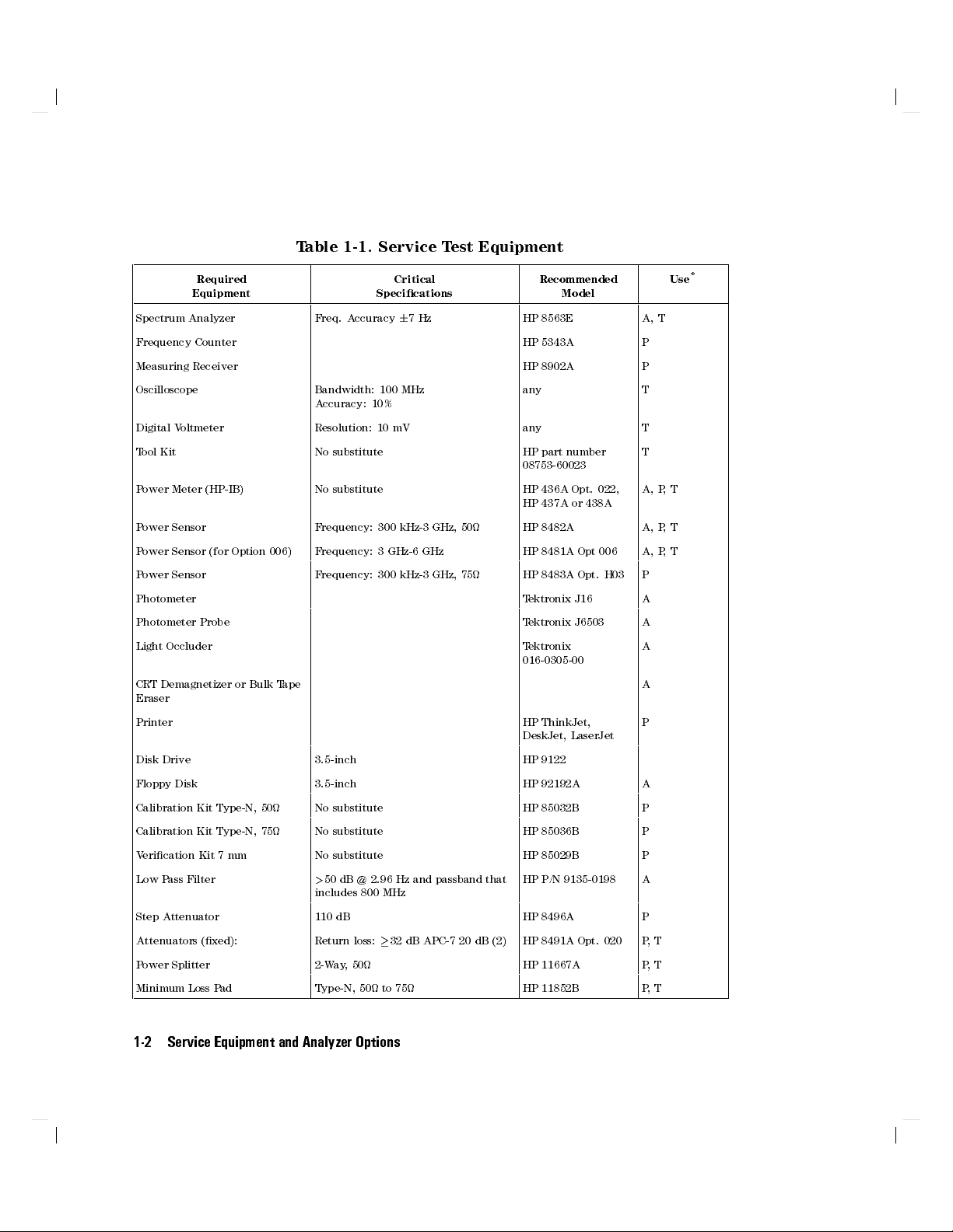
Table 1-1. Service Test Equipment
Required
Equipment
Critical
Specications
Recommended
Model
Spectrum Analyzer Freq. Accuracy67Hz HP 8563E A, T
Frequency Counter HP 5343A P
Measuring Receiver HP 8902A P
Oscilloscope Bandwidth: 100 MHz
any T
Accuracy: 10%
Digital Voltmeter Resolution: 10 mV any T
Tool Kit No substitute HP part number
T
08753-60023
Power Meter (HP-IB) No substitute HP 436A Opt. 022,
A, P,T
HP 437A or 438A
Power Sensor Frequency: 300 kHz-3 GHz, 50 HP 8482A A, P,T
Power Sensor (for Option 006) Frequency: 3 GHz-6 GHz HP 8481A Opt 006 A, P,T
Power Sensor Frequency: 300 kHz-3 GHz, 75 HP 8483A Opt. H03 P
Photometer Tektronix J16 A
Photometer Probe Tektronix J6503 A
Light Occluder Tektronix
A
016-0305-00
CRT Demagnetizer or Bulk Tape
A
Eraser
Printer HP ThinkJet,
P
DeskJet, LaserJet
Disk Drive 3.5-inch HP 9122
Floppy Disk 3.5-inch HP 92192A A
Calibration Kit Type-N, 50 No substitute HP 85032B P
Calibration Kit Type-N, 75 No substitute HP 85036B P
Verication Kit 7 mm No substitute HP 85029B P
Low Pass Filter
>
50 dB @ 2.96 Hz and passband that
HP P/N 9135-0198 A
includes 800 MHz
Step Attenuator 110 dB HP 8496A P
Attenuators (xed): Return loss:32 dB APC-7 20 dB (2) HP 8491A Opt. 020 P,T
Power Splitter 2-Way, 50 HP 11667A P,T
Minimum Loss Pad Type-N, 50 to 75 HP 11852B P,T
Use
*
1-2 Service Equipment and Analyzer Options
Page 31

Table 1-2. Service Test Equipment (2 of 2)
Required
Equipment
Adapter BNC to Alligator Clip HP P/N 8120-1292 A
Adapter APC-3.5 (m) to type-N (f) HP P/N 1250-1750 A, P
Adapter APC-3.5 (f) to type-N (f) HP P/N 1250-1745 A, P
Adapter APC-3.5 (f) to type-N (m) HP P/N 1250-1744 A
Adapter BNC (m) to type-N (f) HP P/N 1250-0077 P
Adapter type-N (m) to type-N (m) HP P/N 1250-1528 P
RF Cable 24-inch, type-N, 75 HP P/N 8120-2408 A, P
RF Cable 24-inch, type-N, 50 HP P/N 8120-4781 A, P
RF Cable Set type-N, 50 HP 11851B P
HP-IB Cable HP 10833A/B/C/D A
Coax Cable BNC HP P/N 8120-1840 A
Coax Cable BNC (m) to BNC (m), 50 HP 10503A A
Antistatic Wrist Strap HP P/N 9300-1367 A, T,P
Antistatic Wrist Strap Cord HP P/N 9300-0980 A, T,P
Static-control Table Mat and
Earth Ground Wire
*P-Performance Tests
A-Adjustment
T - Troubleshooting
Critical
Specications
Recommended
Model
HP P/N 9300-0797 A, T,P
Use
*
Service Equipment and Analyzer Options 1-3
Page 32

Table 1-2. Required Tools
T-8, T-10 and T-15 TORX screwdrivers
Flat-blade screwdrivers|small, medium, and large
5/16-inch open-end wrench (for SMA nuts)
3/16, 5/16, and 9/16-inch hex nut drivers
5/16-inch open-end torque wrench (set to 10 in-lb)
2.5-mm hex-key driver
Non-conductive and non-ferrous adjustment tool
Needle-nose pliers
Tweezers
Antistatic work mat with wrist-strap
1-4 Service Equipment and Analyzer Options
Page 33

Principles of Microwave Connector Care
Proper connector care and connection techniques are critical for accurate,
repeatable measurements.
Refer to the calibration kit documentation for connector care information.
Prior to making connections to the network analyzer, carefully review the
information about inspecting, cleaning and gaging connectors.
Having good connector care and connection techniques extends the life of these
devices. In addition, you obtain the most accurate measurements.
This type of information is typically located in Chapter 3 of the calibration kit
manuals.
For additional connector care instruction, contact your local Hewlett-P
Sales and Service Oce about course numbers HP 85050A+24A and
HP 85050A+24D.
See the following table for quick reference tips about connector care
.
ackard
Service Equipment and Analyzer Options 1-5
Page 34

Table 1-3. Connector Care Quick Reference
Handling and Storage
Do Do Not
Keep connectors clean Touch mating-plane surfaces
Extend sleeve or connector nut Set connectors contact|end down
Use plastic end-caps during storage
Visual Inspection
Do Do Not
Inspect all connectors carefully Use a damaged connector|ever
Look for metal particles, scratches, and dents
Connector Cleaning
Do Do Not
Try compressed air rst Use any abrasives
Use isopropyl alcohol Get liquid into plastic support beads
Clean connector threads
Gaging Connectors
Do Do Not
Clean and zero the gage before use Use an out-of-spec connector
Use the correct gage type
Use correct end of calibration block
Gage all connectors before rst use
Making Connections
Do Do Not
Align connectors carefully Apply bending force to connection
Make preliminary connection lightly Over tighten preliminary connection
Turn only the connector nut Twist or screw any connection
Use a torque wrench for nal connect Tighten past torque wrench \break" point
1-6 Service Equipment and Analyzer Options
Page 35

Analyzer Options Available
Option 003, 3 GHz Operation
This option extends the maximum source and receiver frequency of the analyzer
to 3 GHz.
Option 004, Step Attenuator
This option provides a source output power range from085 to +10 dBm.
Option 006, 6 GHz Operation
This option extends the maximum source and receiver frequency of the analyzer
to 6 GHz.
Option 010, Time Domain
This option displays the time domain response of a network by computing
the inverse Fourier transform of the frequency domain response. It shows
the response of a test device as a function of time or distance
reection coecient of a network versus time determines the magnitude and
location of each discontinuity. Displaying the transmission coecient of a
network versus time determines the characteristics of individual transmission
paths. Time domain operation retains all accuracy inherent with the correction
that is active in such devices as SA
antennas.
W lters,SAW delay lines, RF cables, and RF
. Displaying the
Option 075, 75 Impedance
This option oers 75 impedance bridges with type-N test port connectors.
Option 1CM, Rack Mount Flange Kit Without Handles
This option is a rack mount kit containing a pair of anges and the necessary
hardware to mount the instrument, with handles detached, in an equipment
rack with 482.6 mm (19 inches) horizontal spacing.
Service Equipment and Analyzer Options 1-7
Page 36

Option 1CP, Rack Mount Flange Kit With Handles
This option is a rack mount kit containing a pair of anges and the necessary
hardware to mount the instrument with handles attached in an equipment rack
with 482.6 mm (19 inches) spacing.
Option AFN, add 50 Test Port Cable
This option provides a second type-N male to type-N male test port cable and a
type-N female to type-N female adapter. Instructions are included for storing a
new internal calibration to account for the eects of this cable.
Option AFP, add 75 Test Port Cable
This option provides a 75 type-N male to type-N female test port cable
Instructions are included for storing a new internal calibration to account for
the eects of this cable.
Option B02, External Disk Drive
This option provides an external disk drive and an HP-IB cable
.
.
1-8 Service Equipment and Analyzer Options
Page 37

Service and Support Options
Hewlett-Packards oers many repair and calibration options for your analyzer.
Contact the nearest Hewlett-Packard sales or service oce for information on
options available for your analyzer. See the table titled \Hewlett-Packard Sales
and Service Oces" in Chapter 15.
Service Equipment and Analyzer Options 1-9
Page 38

Page 39

System Verication and Performance
Tests
How to Test the Performance of Your Analyzer
To obtain the same quality of performance testing that Hewlett-Packard has
administered at the factory, you must perform:
the system verication procedure
AND
all
of the performance test procedures.
This quality of performance testing guarantees that the analyzer is performing
within
will issue a Certicate of Calibration for your analyzer if two conditions are
met:
all
of the published specications. A Hewlett-Packard Customer Engineer
Your analyzer passes all the performed tests.
The equipment and standards that were used to perform the tests are
traceable to a national standards institute.
2
Note
If you have a particular type of measurement application that
does not use all of the analyzer's measurement capabilities,
you may ask your local Hewlett-Packard Customer Service
Center for a subset of specications that you want veried.
However, this does create the potential for making incorrect
measurements when using a dierent application.
System Verication and Performance Tests 2-1
Page 40

Sections in this Chapter
HP 8752C System Verication
HP 8752C Performance Tests
1. Reection Test Port Output Frequency Range and Accuracy
2. Reection Test Port Output Power Range and Level Linearity (HP 8752C
without Option 004)
3. Reection Test Port Output Power Range and Level Linearity (HP 8752C
with Option 004)
4. Transmission Test Port Input Noise Floor Level (HP 8752C without
Option 075 )
5. Transmission Test Port Input Noise Floor Level (HP 8752C with
Option 075 )
6. Test Port Crosstalk
7. System Trace Noise
8. Magnitude Dynamic Accuracy (HP 8752C0All Options)
9. Phase Dynamic Accuracy (HP 8752C0All Options)
10. Compression
HP 8752C Performance Test Record
2-2 System Verication and Performance Tests
Page 41

HP 8752C System Verication
Equipment
For standard HP 8752C network analyzer:
Calibration kit (50, type-N)
Cable type-N (50) 24-inch
Printer
::::: :::::: ::::::: ::::::::: ::::::::::::: ::
:::::: :::::: ::::::: ::::::::: ::::::::::::: :
:::::: :::::: ::::::: ::::::::: ::::::::
HP P/N 8120-4781
HP ThinkJet, DeskJet, LaserJet
HP 85032B
For the HP 8752C with Option 075:
Calibration kit (75, type-N)
Cable type-N (75) 24-inch
Printer
::::: :::::: ::::::: ::::::::: ::::::::::::: ::
:::::: :::::: ::::::: ::::::::: ::::::::::::: :
:::::: :::::: ::::::: ::::::::: ::::::::
HP P/N 8120-2408
HP ThinkJet, DeskJet, LaserJet
HP 85036B
Warm-up time: one hour.
Description
The HP 8752C system verication consists of performing the verication
procedure mentioned in this section. The verication procedure is
semi-automated and controlled by the analyzer's rmware.
The verication procedure involves measuring a set of calibration devices
(supplied in the HP 85032B 50 type-N calibration kit or the HP 85036B 75
type-N calibration kit) and comparing the measured data to the specication
limits drawn on the analyzer display. The measured data must fall within the
specication limits at all frequencies to pass the test.
System verication is only part of an instrument's calibration procedure.
The complete set of instrument specications can be tested by performing
the \HP 8752C System Verication" and all of the analyzer's performance
tests. An HP 85032B Option 002 or an HP 85036B Option 1BP calibration kit
(including with a Certicate of Calibration with United States National Institute
of Standards and Technology (NIST) test numbers) is required for a calibration
traceable to NIST.
Note
A Certicate of Calibration is issued if the analyzer's system
verication as well as all of the performance tests are
performed by a Hewlett-Packard Customer Engineer with all
having passed.
System Verication and Performance Tests 2-3
Page 42

System Verication Cycle and Kit Recertication
The recommended system verication cycle is every six months. Hewlett-
Packard also suggests the calibration kit be recertied annually.For more
information about the kit recertication, refer to the
HP 85032B 50 Type-N
Calibration Kit Operation and Service ManualorHP 85036B 75 Type-N
Calibration Kit Operation and Service Manual
.
Measurement Uncertainty
Associated with any analyzer are measurement errors that add uncertainty to
the measured results. This uncertainty limits how accurately a device under test
(DUT) can be measured.
The measurement uncertainty is dened to be the sum of the residual
systematic (repeatable) and random (non-repeatable) errors in the measurement
system. The systematic errors are eective directivity, eective source match,
load match, reection and transmission tracking, and isolation (crosstalk).
Random errors include errors due to noise, drift, connector repeatability, and
test cable stability.
The typical measurement uncertainties for type-N connectors using a
1-port error correction utilize an RSS (Root Sum of Squares) model for the
contributions of random errors such as noise, pin depth, pin diameter variation,
load return loss, and connector repeatability.
Measurement Uncertainty Window
The PASS/FAIL result of the limit line test generally indicates the status of the
verication test. The validity of the limit lines, drawn on the analyzer display
during the verication tests, are determined by the measurement uncertainty.
The measurement uncertainty must be taken into account when analyzing
the test results. If the analyzer detects the test data outside of the limits,a
FAIL
will be displayed on the analyzer. This
FAIL
status may not represent
a true failure if at the worst point, the test data is within the measurement
uncertainty window (not displayed on the analyzer). Refer to Figure 2-1 for
interpretations of test data.
2-4 System Verication and Performance Tests
Page 43

Figure 2-1. Measurement Uncertainty Window
System Verication and Performance Tests 2-5
Page 44

HP 8752C Type-N Test Port Characteristics (50 System)
Directivity
Frequency Range Specication Measurement Uncertainty
300 kHz to 1.3 GHz 40 dB
1.3 GHz to 3.0 GHz 35 dB
3.0 GHz to 6.0 GHz 30 dB
1
30 dB, 300 kHz to 10 MHz
1
6
3.30 dB
6
2.51 dB
6
3.30 dB
Source Match (Reection)
Frequency Range Specication Measurement Uncertainty
300 kHz to 1.3 GHz 30 dB
1.3 GHz to 3.0 GHz 25 dB
3.0 GHz to 6.0 GHz 20 dB
6
2.51 dB
6
2.88 dB
6
2.88 dB
Source Match (Transmission)*
Frequency Range Specication Measurement Uncertainty
300 kHz to 1.3 GHz 23 dB
1.3 GHz to 3.0 GHz 20 dB
3.0 GHz to 6.0 GHz 16 dB
6
2.51 dB
6
2.88 dB
6
2.88 dB
*Option 004 may degrade transmission source match as much as 2 dB, resulting in up to 0.05 dB additional
uncertainty in transmission tracking.
Reection Tracking
Frequency Range Specication Measurement Uncertainty
300 kHz to 1.3 GHz
1.3 GHz to 3.0 GHz
3.0 GHz to 6.0 GHz
2-6 System Verication and Performance Tests
6
0.2 dB
6
0.3 dB
6
0.4 dB
6
0.009 dB
6
0.019 dB
6
0.070 dB
Page 45

Load Match
Frequency Range Specication Measurement Uncertainty
300 kHz to 1.3 GHz 23 dB
1.3 GHz to 3.0 GHz 20 dB
3.0 GHz to 6.0 GHz 18 dB
1
14 dB, 300 kHz to 10 MHz for analyzers with option 006
1
6
0.40 dB
6
0.40 dB
6
0.92 dB
Transmission Tracking
Frequency Range Specication Measurement Uncertainty
300 kHz to 1.3 GHz
1.3 GHz to 3.0 GHz
3.0 GHz to 6.0 GHz
6
6
6
0.2 dB
0.3 dB
0.5 dB
6
0.043 dB
6
0.086 dB
6
0.172 dB
HP 8752C Type-N Test Port Characteristics (75 System)
Directivity
Frequency Range Specication Measurement Uncertainty
300 kHz to 10 MHz 30 dB
10 MHz to 1.3 GHz 40 dB
1.3 GHz to 3.0 GHz 35 dB
6
4.41 dB
6
4.41 dB
6
4.41 dB
Source Match (Reection)
Frequency Range Specication Measurement Uncertainty
300 kHz to 1.3 GHz 30 dB
1.3 GHz to 3.0 GHz 25 dB
6
2.88 dB
6
3.30 dB
System Verication and Performance Tests 2-7
Page 46

Source Match (Transmission)*
Frequency Range Specication Measurement Uncertainty
300 kHz to 1.3 GHz 23 dB
1.3 GHz to 3.0 GHz 20 dB
6
2.88 dB
6
3.30 dB
*Option 004 may degrade transmission source match as much as 2 dB, resulting in up to 0.05 dB additional
uncertainty in transmission tracking.
Reection Tracking
Frequency Range Specication Measurement Uncertainty
300 kHz to 1.3 GHz
1.3 GHz to 3.0 GHz
6
0.2 dB
6
0.3 dB
6
0.2 dB
6
0.3 dB
Load Match
Frequency Range Specication Measurement Uncertainty
300 kHz to 1.3 GHz 23 dB
1.3 GHz to 3.0 GHz 20 dB
6
0.50 dB
6
0.64 dB
Transmission Tracking
Frequency Range Specication Measurement Uncertainty
300 kHz to 1.3 GHz
1.3 GHz to 3.0 GHz
2-8 System Verication and Performance Tests
6
0.2 dB
6
0.3 dB
6
0.20 dB
6
0.30 dB
Page 47

System Verication Procedure
1. Switch the analyzer's line power ON. Press
2. If you want a printout of the verication data, press
NNNNNNNNNNNNNNNNNNNNNNNNNNNNNNNNNNNNNNNNNNNNNNNNNNNNN
SYSTEM CONTROLLER
4
SYSTEM
NNNNNNNNNNNNNNNNNNNNNNNNNNNNNNNNNNNNNN
5
SERVICE MENU
4
PRESET
5
.
4
NNNNNNNNNNNNNNNNNNNNNNNNNNNNNNNNNNNNNN
TEST OPTIONS
LOCAL
5
NNNNNNNNNNNNNNNNNNNNNNNNNNNNN
RECORD ON
.
Otherwise, go to the next step.
Note
Once you have activated the record function, you
cannot
switch
it OFF during the verication procedure. Be sure the paper in
the printer is setup so that printing starts at the top of the page.
In case of printer diculty:
If you have an HP-IB compatible printer, verify that the printer
address is set to 1.
Refer to the
HP 8752C Network Analyzer User's Guide
for more
information on how to perform this task.
3. Press
4. Connect a type-N male open to the analyzer's reection test port. Press
5. When the measurement is done, connect a type-N male short to the reection
4
SYSTEM
brief description of the test procedure is shown on the analyzer display
begin the test, press
5
SERVICE MENU
NNNNNNNNNNNNNNNNNNNNNNNNNN
CONTINUE
NNNNNNNNNNNNNNNNNNNNNNNNNN
CONTINUE
test port. Press
.
NNNNNNNNNNNNNNNNNNNNNNNNN
N
CONTINUE
NNNNNNNNNNNNNNNNNNNNNNNNNNNNNNNNNNNNNN
.
NNNNNNNNNNNNNNNNN
TESTS
.
NNNNNNNNNNNNNNNNNNNNNNNNNNNNNNNNNNNNNNNNN
SYS VER TESTS
NNNNNNNNNNNNNNNNNNNNNNNNNNNNNNNNNNNNNN
EXECUTE TEST
.A
.To
6. At the prompt, connect a type-N load to the reection test port. Press
NNNNNNNNNNNNNNNNNNNNNNNNNN
CONTINUE
. After measuring the load, the system directivity is checked and
the test result is displayed on the analyzer.
NNNNNNNNNNNNNNNNNNNNNNNNNNNNN
Note
If you have not activated the
NNNNNNNNNNNNNNNNNNNNNNNNNN
press
CONTINUE
after EACH of the following tests:
RECORD ON
feature, you need to
a. Source Match (Reection Mode)
b. Source Match (Transmission Mode)
c. Reection Tracking
System Verication and Performance Tests 2-9
Page 48

7. Connect a type-N RF cable between the analyzer's reection and
transmission test ports. Press
NNNNNNNNNNNNNNNNNNNNNNNNNN
CONTINUE
to test the system load match.
8. If you have activated the record feature, the system will automatically test
its transmission tracking. Otherwise, press
9.
In case of diculty
1. Refer to the \Adjustments and Correction Constants" chapter of this manual.
NNNNNNNNNNNNNNNNNNNNNNNNNN
Press
CONTINUE
Perform the \Frequency Response Correction Constants A
procedure. Repeat the \HP 8752C System Verication" procedure.
to end the system verication procedure.
NNNNNNNNNNNNNNNNNNNNNNNNNN
CONTINUE
to access this test.
djustment"
2-10 System Verication and Performance Tests
Page 49

HP 8752C Performance Tests
This portion of the manual contains performance tests which are part of the
instrument calibration process. An instrument calibration includes the system
verication, described in the previous section, and the performance tests.
To test the complete set of instrument specications, both portions of the
instrument calibration must be performed.
Note
The following is a list of performance tests in the order in which they should be
performed:
1. Reection Test Port Output Frequency Range and Accuracy
2. Reection Test Port Output Power Range and Level Linearity (For HP 8752C
Analyzers without Option 004)
3. Reection Test Port Output Power Range and Level Linearity (For HP 8752C
Analyzers with Option 004)
4. Transmission Test Port Input Noise Floor Level (For HP 8752C Analyzers
without Option 075)
5. Transmission Test Port Input Noise Floor Level (For HP 8752C Analyzers
with Option 075)
6. Test Port Crosstalk
7. System Trace Noise
8. Magnitude Dynamic Accuracy
9. Phase Dynamic Accuracy
Before performing these performance tests, check that the test
equipment is operating to specication. Gage and clean all
connectors.
10. Compression
Note
Unless otherwise specied, the performance tests are applicable
to a standard HP 8752C or an HP 8752C with options.
System Verication and Performance Tests 2-11
Page 50

Equipment Required to Run the Performance Tests
Description Quantity HP Model or Part Number
Calibration kit, 50 type-N 1 HP 85032B
Calibration kit, 75 type-N 1 HP 85036B
1
Measuring Receiver 1 HP 8902A
Frequency counter 1 HP 5343A
Power meter 1 HP 436A, HP 437A, HP 438A
Power sensor 1 HP 8482A
Power sensor 1 HP 8481A
Power sensor 1 HP 8483A
Power sensor 1 HP 8483A Option H03
2
1
3
Printer 1 HP ThinkJet, DeskJet,
LaserJet
110 dB step attenuator 1 HP 8496A
2-Way power splitter, 50 1 HP 11667A
Cable, 50 type-N 24-inch 3 HP P/N 8120-4781
Cable, 75 type-N 24-inch 2 HP P/N 8120-2408
Minimum Loss Pad 2 HP 11852B
1
1
Adapter type-N(m) to type-N(m) 1 HP P/M 1250-1528
Adapter BNC(m) to N(f) 1 HP P/N 1250-0077
Adapter APC-3.5mm(f) to N(f) 1 HP P/N 1250-1745
1
Required only for instruments with Option 075
2
Required only for instruments with Option 006
3
Required only for instruments with Option 003 and Option 075
2-12 System Verication and Performance Tests
Page 51

1. Reection Test Port Output Frequency Range and
Accuracy
Specications
Frequency Range Frequency Accuracy
300 kHz to 1.3 GH
C65
2
3
C
300 kHz to 3 GHz
300 kHz to 6 GHz
1
At 25
2
HP 8752C with Option 003
3
HP 8752C with Option 006
6
10 ppm
6
10 ppm
6
10 ppm
1
Equipment
Frequency counter
Adapter BNC(m) to N(f)
:::::: ::::::: :::::: ::::::::: :::::::::::::: :::::: :::::
::::::: ::::::: ::::::: ::::::::: :::::::::
Adapter APC-3.5(f) to N(f)
Cable (50, type-N) 24-inch
:::::: :::::: ::::::: ::::::::: ::::::::
::::::: ::::::: ::::::: :::::::: ::::::
HP P/N 1250-0077
HP P/N 1250-1745
HP P/N 8120-4781
HP 5343A
Additional equipment required for analyzers with Option 075
50 to 75 minimum loss pad
:::::: :::::: ::::::: ::::::::: ::::::::::::
HP 11852B
Warm-up time: 30 minutes.
Description
This test determines the analyzer's reection test port output frequency range
and accuracy over its entire operating frequency range. The frequencies are
veried relative to room temperature (25C,65
C).
System Verication and Performance Tests 2-13
Page 52

Procedure
1. Connect the equipment as shown in Figure 2-2. Press
4
PRESET
5
.
Figure 2-2.
Reection Test Port Output Frequency Range and Accuracy Test Setup
2.
Press
4
MENU
NNNNNNNNNNNNNNNNNNNNNNN
5
CW FREQ
4
354054054k/m
5
. Depending on the analyzer's options,
record the frequency counter reading in the appropriate table (2 through 6)
in the \Performance Test Record."
3. Repeat step 2 for each instrument's CW frequency listed in the appropriate
table (2 through 6) in the \Performance Test Record."
In case of diculty
1. If any measured frequency barely fails the specication, check the time base
accuracy of the frequency counter.
2. If the analyzer fails by a signicant margin at
all
frequencies, perform the
\Frequency Accuracy" and the \High/Low Band Transition" adjustments.
Refer to the chapter titled \Adjustments and Correction Constants" for more
information on how to perform these adjustment procedures.
3. Refer to the \Source Troubleshooting" chapter in this manual if the problem
still persists.
2-14 System Verication and Performance Tests
Page 53

2. Reection Test Port Output Power Range and Level
Linearity (For HP 8752C Analyzers without
Option 004)
Specications
Power Range Power Level Linearity Relative to05 dBm
0
20 to015 dBm
0
15 to 0 dBm
0 to +5 dBm
6
0.5 dB
6
0.2 dB
6
0.5 dB
Equipment
For standard analyzers:
Power meter
Power sensor
:::::: ::::::: ::::::: :::::::: :::::::::::::: ::::::
::::::: :::::: ::::::: ::::::::: ::::::::::::: ::::::: ::::::: :::
HP 436A/437B/438A
HP 8482A
Additional equipment required for analyzers with Option 006
Power sensor
::::::: :::::: ::::::: ::::::::: ::::::::::::: ::::::: ::::::: :::
HP 8481A
Equipment required for analyzers with Option 075
Power meter
Power sensor
:::::: ::::::: ::::::: :::::::: :::::::::::::: ::::::
::::::: :::::: ::::::: ::::::::: ::::::::::::: ::::::: ::::::: :::
HP 436A/437B/438A
HP 8483A
Warm-up time: 30 minutes.
Description
This test determines the reection test port output power range and level
linearity for all analyzers without Option 004. The specications are veried
by rst setting a reference at05 dBm for relative power measurements. Next,
the analyzer's reection test port output power is stepped and measured over
its operating power range. The power level linearity is found by calculating the
dierence between the power meter reading and the power oset listed in the
appropriate table (7 through 13) of the \Performance Test Record."
System Verication and Performance Tests 2-15
Page 54

Procedure
Power Range and Level Linearity for an HP 8752C or an HP 8752C
Option 075
1. Connect the equipment as shown in Figure 2-3 .
Note
For instruments with Option 075:
a. use an HP 8483A (75) power sensor
b. use tables 11 through 13 in the \Performance Test Record."
For instruments with Option 075
and
Option 003, use an
HP 8483A Option H03 (75) power sensor.
Figure 2-3.
Reection Test Port Output Power Range and Level Linearity Test Setup
2. Zero and calibrate the power meter.For more information on how to
perform this task, refer to the power meter Operating and Service manual.
3.
4.
Press
Press
4
PRESET54MENU
NNNNNNNNNNNNNNNNN
POWER
4
054554x1
NNNNNNNNNNNNNNNNNNNNNNN
5
CW FREQ
5
. Set the power meter cal factor for this CW
4
354054054k/m
5
.
frequency. On the power meter, set the current power level as the
reference for relative power (dB) measurements. This can be done by
2-16 System Verication and Performance Tests
Page 55

pressing
4
dB REF
5
on an HP 436A or
4
5
on an HP 438A power meter front
REL
panel.
Press
NNNNNNNNNNNNNNNNN
POWER
4054254054x15
. Record the power meter reading in the \Results
5.
Measured" column on the \Performance Test Record."
6. Utilizing the Power Oset value listed in the \Performance Test Record,"
calculate the test port output power level linearity using the following
formula:
Power Level Linearity = Measured Value + Power Oset
7. Record the result of your calculation on the \Performance Test Record."
8. Repeat steps 5, 6, and 7 for the other power levels listed in the \HP 8752C
Performance Test Record (7 of 28)."
9.
Press
4
MENU
Press
NNNNNNNNNNNNNNNNN
POWER
10.
frequency. Press the appropriate hardkey (
NNNNNNNNNNNNNNNNNNNNNNN
5
CW FREQ
4
054554x1
4
154.54354G/n
5
. Set the power meter cal factor for this CW
5
.
4
dB REF
5or4
REL
5
) on the
HP 436A/438A power meter front panel for relative power measurements
11. Repeat steps 5, 6, and 7 for the other power levels listed in the \HP 8752C
Performance Test Record (8 of 28)."
12. This completes the \Reection Test Port Output Power Range and Level
Linearity" test if you are working with either a standard analyzer or an
analyzer with only Option 075. Otherwise, go to the appropriate section
below to continue the reection test port performance tests for other
options.
.
Power Range and Level Linearity for an HP 8752C with Option 003
NNNNNNNNNNNNNNNNNNNNNN
13.
Press
4
MENU
Press
NNNNNNNNNNNNNNNNN
POWER
14.
frequency. Press the appropriate softkey (
N
5
CW FREQ
4054554x15
4354
G/n
5
.
. Set the power meter cal factor for this CW
4
dB REF
5or4
5
) on the power
REL
meter front panel for relative power measurements.
Press
NNNNNNNNNNNNNNNNN
POWER
4
054254054x1
5
. Record the power meter reading in the
15.
\Measured Value" column on the \HP 8752C Performance Test Record
(9 of 28)."
System Verication and Performance Tests 2-17
Page 56

16. Utilizing the Power Oset value listed in the \Performance Test Record
(9 of 28)," calculate the Power Level Linearity using the following formula:
Power Level Linearity = Measured Value + Power Oset
17. Record the result of your calculation on the \Performance Test Record
(9 of 28)."
18. Repeat steps 15, 16, and 17 for the other power levels listed in the
\Performance Test Record (9 of 28)."
Power Range and Level Linearity for an HP 8752C with Options 003
and 075
NNNNNNNNNNNNNNNNNNNNNNN
19. Press
4
MENU
5
CW FREQ
4
254G/n
5
.
20. Perform steps 14, 15, 16, and 17 for the power levels listed in the
\Performance Test Record (12 of 28)."
Power Range and Level Linearity for an HP 8752C with Option 006
21.
Press
4
MENU
NNNNNNNNNNNNNNNNNNNNNNN
5
CW FREQ
4
654G/n
5
.
22. Perform steps 14, 15, 16, 17, and 18 for the power levels listed in the
\Performance Test Record (10 of 28)."
In case of diculty
1. If you cannot set the test port power at any power level, be sure the
analyzer's source power is activated. Todoso, press
NNNNNNNNNNNNNNNNNNNNNNNNNNNNNNNN
the
SOURCE PWR
softkey.ONshould be highlighted.
4
MENU
NNNNNNNNNNNNNNNNN
5
POWER
. Check
2. Refer to the \Adjustments and Correction Constants" chapter in this manual.
Perform the \RF Output Power Correction Constants Adjustment" procedure.
3. If the problem still exists, refer to the \Source Troubleshooting" chapter in
this manual for more troubleshooting information.
2-18 System Verication and Performance Tests
Page 57

3. Reection Test Port Output Power Range and Level
Linearity (HP 8752C with Option 004)
Specications
HP 8752C Option Power Range Power Level Linearity
Option 004
Options 004 and 075
1
Relative to05 dBm
0
85 to +10 dBm
0
85 to +8 dBm
6
0.2 dB (015 to +5 dBm)
6
0.5 dB (+5 to +10 dBm)
6
0.2 dB (015 to +5 dBm)
6
0.5 dB (+5 to +8 dBm)
Equipment
For standard analyzers:
Power meter
Power sensor
Cable (50, type-N) 24-inch
::::::: ::::::: :::::: ::::::::: ::::::::::::: :::::::
::::::: :::::: ::::::: ::::::::: ::::::::::::: ::::::: ::::::: :::
::::::: ::::::: ::::::: :::::::: ::::::
Additional equipment required for analyzers with Option 006
Power sensor
::::::: :::::: ::::::: ::::::::: ::::::::::::: ::::::: ::::::: :::
Equipment required for analyzers with Option 075
Power meter
Power sensor
Cable (75, type-N) 24-inch
::::::: ::::::: :::::: ::::::::: ::::::::::::: :::::::
::::::: :::::: ::::::: ::::::::: ::::::::::::: ::::::: ::::::: :::
::::::: ::::::: ::::::: :::::::: ::::::
Warm-up time: 30 minutes.
1
HP436A/437B/438A
HP 8482A
HP P/N 1250-1745
HP 8481A
HP436A/437B/438A
HP 8483A
HP P/N 8120-2408
Description
This test determines the reection test port output power range and level
linearity for an analyzer with Option 004. To verify the analyzer power ranges,
a power level of010 dBm is rst selected and normalized. Next, various
power levels in dierent power ranges are selected and compared to the
specications listed in the \Performance Test Record." The analyzer power level
linearity is conrmed by rst setting a reference (at05 dBm) for relative power
measurements. Next, the analyzer's reection test port output power is stepped
System Verication and Performance Tests 2-19
Page 58

and measured over its specied power range. The power level linearity is found
by calculating the dierence between the power meter reading and the power
oset listed in the \Performance Test Record."
Procedure
Power Range for an HP 8752C with Option 004
1. Connect the equipment as shown in Figure 2-4.
Figure 2-4.
Reection Test Port Output Power Range Test Setup
(HP 8752C Option 004)
2. Press
3.
4
PRESET54CH 2
Press
4
5
NNNNNNNNNNNNNNNNNNNNNNNNNNNNNNNNNNNNNNNNNNNNNNNNNNNNNNNNNNNN
MENU
NNNNNNNNNNNNNNNNN
POWER
5
to set the analyzer up for transmission measurements.
NNNNNNNNNNNNNNNNNNNNNNNNNNNNNNNNNNNNNNNNN
PWR RANGE MAN
RANGE 0015 to +10
NNNNNNNNNNNNNNNNNNNNNNNNNNNNNNNNNNNNNN
POWER RANGES
. Enter the power level value listed in the
the \Performance Test Record (14 of 28)." For this power range, press
4054x15
.
4.
Press
4
DISPLAY
NNNNNNNNNNNNNNNNNNNNNNNNNNNNNNNNNNNNN
5
DATA!MEMORY
NNNNNNNNNNNNNNNNNNNNNNNNNN
DATA/MEM
4
SCALE REF
NNNNNNNNNNNNNNNNNNNNNNNNNNNNN
5
SCALE/DIV
normalize and scale down the data trace.
5. To activate the analyzer's statistic feature, press
NNNNNNNNNNNNNNNNNNNNNNNNNNNNNNNNNNNNNNNNNNNNNNNNNN
MARKER MODE MENU
6.
Press
4
5
MENU
NNNNNNNNNNNNNNNNNNNNNNNNNNNNNNNNNNNNNN
TRIGGER MENU
NNNNNNNNNNNNNNNNNNNNNNNNNN
STATS ON
NNNNNNNNNNNNNNNNNNNNNNNNNNNNNNNNNNNNNNNNNNNNNNNNNN
NUMBER of GROUPS
.
4
MKR FCTN
4
5
554x1
5
.
2-20 System Verication and Performance Tests
405415
4.54554x15
to
Page 59

7. When the analyzer nishes the sweeps, record the data trace mean value
(as shown on the upper right-hand corner of the analyzer display) on the
\Performance Test Record (14 of 28)."
8.
Press
4
MENU
NNNNNNNNNNNNNNNNN
5
POWER
NNNNNNNNNNNNNNNNNNNNNNNNNNNNNNNNNNNNNN
POWER RANGES
NNNNNNNNNNNNNNNNNNNNNNNNNNNNNNNNNNNNNNNNNNNNNNNNNNN
RANGE 1025 to 0
. Enter the power
level value listed in the \Performance Test Record." For this power range,
press
4054254054x15
.
9. Repeat steps 6, 7 and 8 for the other power ranges listed in the \Performance
Test Record (14 of 28)."
Power Level Linearity for an HP 8752C with Option 004
or an HP 8752C withOptions 004 and 075
1. Connect the equipment as shown in Figure 2-5.
Note
For instruments with Option 075:
a. use an HP 8483A (75) power sensor
b. use tables 19 through 21 in the \P
For instruments with Option 075
use an HP 8483A Option H03 (75) power sensor
erformance Test Record."
and
Option 003,
.
Figure 2-5.
Reection Test Port Output Power Level Linearity Test Setup
System Verication and Performance Tests 2-21
Page 60

2. Zero and calibrate the power meter.For more information on how to
perform this task, refer to the power meter's Operating and Service manual.
3.
4.
Press
Press
4
PRESET54MENU
NNNNNNNNNNNNNNNNN
POWER
4054554x15
NNNNNNNNNNNNNNNNNNNNNNN
5
CW FREQ
4354054054
k/m
5
.
. Set the power meter cal factor for this CW
frequency. On the power meter, set the current power level as the
reference for relative power (dB) measurements by pressing
HP 436A or
5.
Press
NNNNNNNNNNNNNNNNN
POWER
4
5
on an HP 438A power meter's front panel.
REL
4054154554x15
. Record the power meter reading in the \Results
4
dB REF
5
on an
Measured" column on the \Performance Test Record."
6. Utilizing the Power Oset value listed in the \Performance Test Record,"
calculate the Power Level Linearity using the following formula:
Power Level Linearity = Measured Value + Power Oset
7. Record the result of your calculation on the \P
erformance Test Record."
8. Repeat steps 5, 6 and 7 for the other power levels listed in the
\Performance Test Record."
NNNNNNNNNNNNNNNNNNNNNNN
9. Press
10.
4
5
MENU
CW FREQ
4
154.54354G/n
5
.
NNNNNNNNNNNNNNNNN
Press
POWER
4
054554x1
5
. Set the power meter cal factor for this CW
frequency. Press the appropriate hardkey (
4
dB REF
5or4
REL
5
) on the
HP 436A/438A power meter front panel for relative power measurements
11. Repeat steps 5, 6, 7 and 8.
12. This completes the \Reection Test Port Output Power Range and Level
Linearity" test if you are working with either an analyzer Option 004 or
an analyzer with Options 004 and 075. Otherwise, go to the appropriate
following section to ensure the reection test port meets specications at
the extended frequency range.
Power Level Linearity for an HP 8752C with Options 003 and 004
13.
Press
4
MENU
Press
NNNNNNNNNNNNNNNNN
POWER
14.
frequency. Press the appropriate hardkey (
NNNNNNNNNNNNNNNNNNNNNNN
5
CW FREQ
4
054554x1
4
5
5
354G/n
.
. Set the power meter cal factor for this CW
4
dB REF
5or4
5
) on the power
REL
meter front panel for relative power measurements.
.
2-22 System Verication and Performance Tests
Page 61

N
Press
NNNNNNNNNNNNNNNN
POWER
4054154554x15
. Record the power meter reading in the \Results
15.
Measured" column on the \Performance Test Record."
16. Utilizing the Power Oset value listed in the \Performance Test Record,"
calculate the Power Level Linearity using the following formula:
Power Level Linearity = Measured Value + Power Oset
17. Record the result of your calculation on the \Performance Test Record."
18. Repeat steps 15, 16 and 17 for the other power levels listed in the
\Performance Test Record."
Power Level Linearity for an HP 8752C with Options 004 and 006
NNNNNNNNNNNNNNNNNNNNNN
19.
Press
4
MENU
N
5
CW FREQ
4
654G/n
5
.
20. Repeat steps 14, 15, 16, 17 and 18 for the power levels listed in the
\Performance Test Record."
Power Level Linearity for an HP 8752C with Options 003, 004,
and 075
NNNNNNNNNNNNNNNNNNNNNNN
21. Press
4
MENU
5
CW FREQ
4
254G/n
5
.
22. Perform steps 14, 15, 16, 17 and 18 for the power levels listed in the
\Performance Test Record."
In case of diculty
1. If you cannot set the test port power at any power level, be sure the
analyzer's source power is activated. Todoso, press
NNNNNNNNNNNNNNNNNNNNNNNNNNNNNNNN
the
SOURCE PWR
softkey. \ON" should be highlighted.
4
MENU
NNNNNNNNNNNNNNNNN
5
POWER
. Check
2. Refer to the \Adjustments and Correction Constants" chapter in this manual.
Perform the \RF Output Power Correction Constants Adjustment" procedure.
3. If the problem still exists, refer to the \Source Troubleshooting" chapter in
this manual for more troubleshooting information.
System Verication and Performance Tests 2-23
Page 62

4. Transmission Test Port Input Noise Floor Level
(HP 8752C without Option 075)
Specications
Frequency Range IF Bandwidth Average Noise Floor Level
(Transmission)
300 kHz to 1.3 GHz 3 kHz
300 kHz to 1.3 GHz 10 Hz
300 kHz to 3 GHz
300 kHz to 3 GHz
3 GHz to 6 GHz
3 GHz to 6 GHz
1
HP 8752C with Option 003
2
HP 8752C with Option 006
1
1
2
2
3 kHz
10 Hz
3 kHz
10 Hz
0
90 dBm
0
110 dBm
0
90 dBm
0
110 dBm
0
85 dBm
0
105 dBm
Equipment
Calibration kit (50, type-N)
Cable (50, type-N) 24-inch
::::: ::::::: :::::: ::::::::: :::::::::::::: :
:::::: ::::::: ::::::: ::::::::: ::::::
HP P/N 8120-4781
HP 85032B
Warm-up time: one hour.
Description
This test determines the analyzer's transmission test port input noise oor level.
It is tested at 0 dBm at two dierent IF bandwidths.
Procedure
Noise Floor Level at 300 kHz to 1.3 GHz (Standard Option), 300 kHz
to 3 GHz (Option 003), or 300 kHz to 6 GHz (Option 006) with an IF
BW of 3 kHz
1. Connect the equipment as shown in Figure 2-6 .
2-24 System Verication and Performance Tests
Page 63

Figure 2-6.
Transmission Test Port Input Noise Floor Level Test Setup 1
2.
Press
4
PRESET54MENU
If your analyzer has Option 003, press
If your analyzer has Option 006, press
3.
Press
4
MEAS
NNNNNNNNNNNNNNNNNNNNNNNNNNNNNNNNNNN
5
INPUT PORTS
NNNNNNNNNNNNNNNNN
5
POWER
4
NNNNN
B
054x1
4
DISPLAY
5
.
4
STOP54354G/n
4
STOP54654G/n
NNNNNNNNNNNNNNNNNNNNNNNNNNNNNNNNNNNNN
5
DATA!MEMORY
4. Connect the equipment as shown in Figure 2-7.
Figure 2-7.
Transmission Test Port Input Noise Floor Level Test Setup 2
5
.
5
.
NNNNNNNNNNNNNNNNNNNNNNNNNN
DATA/MEM
.
System Verication and Performance Tests 2-25
Page 64

5.
If your analyzer has Option 004, press
NNNNNNNNNNNNNNNNNNNNNNN
LIN MAG
4
SCALE REF
NNNNNNNNNNNNNNNNNNNNNNNNNNNNN
5
AUTOSCALE
4
MENU
.
NNNNNNNNNNNNNNNNN
5
POWER
4054854554x154
FORMAT
NNNNNNNNNNNNNNNNN
If your analyzer does not have Option 004 installed, press
4254054x154
6.
Press
NNNNNNNNNNNNNNNNNNNN
SINGLE
FORMAT
4
MKR FCTN
.
NNNNNNNNNNNNNNNNNNNNNNN
5
LIN MAG
N
NNNNNNNNNNNNNNNNNNNNNNNNNNNNNNNNNNNNNNNNNNNNNNNNN
5
MARKER MODE MENU
4
SCALE REF
NNNNNNNNNNNNNNNNNNNNNNNNNNNNN
5
AUTOSCALE
NNNNNNNNNNNNNNNNNNNNNNNNNN
STATS ON
4
MENU
4
MENU
.
N
NNNNNNNNNNNNNNNNNNNNNNNNNNNNNNNNNNNNN
5
TRIGGER MENU
5
POWER
7. When the trace is settled, record its mean value as shown on the analyzer
display.
8. Use the equation:
5
405
Power (dBm) = 20 *flog
(linear magnitude mean value)
10
g
to convert the linear magnitude mean value (measured in step 7) to log
magnitude. Record this calculated value on the \P
erformance Test Record
(22 of 28)."
Note
If your analyzer has Option 003, then record the value
calculated during the previous step (step 8) on the \P
erformance
Test Record" under section HP 8752C Option 003 ONLY.
Noise Floor Level at 300 kHz to 1.3 GHz (Standard Option) or
300 kHz to 3 GHz (Option 003) with an IF B
9.
10.
Press
Press
4
AVG
4
MENU
NNNNNNNNNNNNNNNNN
5
IF BW
4
154054x1
NNNNNNNNNNNNNNNNNNNNNNNNNNNNNNNNNNNNNN
5
TRIGGER MENU
5
to change the IF bandwidth to 10 Hz.
NNNNNNNNNNNNNNNNNNNN
SINGLE
.
Wof10Hz
11. When the sweep is done, record its mean value. Use the equation:
Power (dBm) = 20 *flog10(linear magnitude mean value)
to convert the linear magnitude mean value to log magnitude
g
. Record this
calculated value on the \Performance Test Record (22 of 28)."
12. This completes the \Transmission Test Port Input Noise Floor Level" test
if you are working with either a standard analyzer or an analyzer with
Option 003. Proceed to the next section if your analyzer has Option 006
installed.
2-26 System Verication and Performance Tests
Page 65

Noise Floor Level at 3 GHz to 6 GHz (Option 006) with an IF BWof
10 Hz
13. Press
4
START54354G/n54STOP54654G/n
5
. Connect the equipment as shown in
Figure 2-8.
Figure 2-8.
Transmission Test Port Input Noise Floor Level Test Setup 1
N
14.
Press
4
MENU
15.
When the sweep is nished, press
NNNNNNNNNNNNNNNN
5
POWER
4
054x154MENU
N
NNNNNNNNNNNNNNNNNNNNNNNNNNNNNNNNNNNNN
5
TRIGGER MENU
4
DISPLAY
Connect the equipment as shown in Figure 2-9.
NNNNNNNNNNNNNNNNNNNN
SINGLE
NNNNNNNNNNNNNNNNNNNNNNNNNNNNNNNNNNNNN
5
DATA!MEMORY
.
4
DATA/MEM
5
.
Figure 2-9.
Transmission Test Port Input Noise Floor Level Test Setup 2
System Verication and Performance Tests 2-27
Page 66

.
NNNNNNNNNNNNNNNNN
5
POWER
4054854554x154
16.
If your analyzer has Option 004, press
NNNNNNNNNNNNNNNNNNNNNNNNNNNNNNNNNNNNNN
TRIGGER MENU
If your analyzer does not have Option 004 installed, press
4254054x154
MENU
NNNNNNNNNNNNNNNNNNNN
SINGLE
.
NNNNNNNNNNNNNNNNNNNNNNNNNNNNNNNNNNNNNN
5
TRIGGER MENU
4
MENU
NNNNNNNNNNNNNNNNNNNN
SINGLE
17. When the measurement is done, record the mean value.
18. Use the equation:
4
MENU
MENU
NNNNNNNNNNNNNNNNN
5
POWER
5
405
Power (dBm) = 20 *flog10(linear magnitude mean value)
g
to convert the linear magnitude mean value (measured in step 17) to log
magnitude. Record this calculated value on the \Performance Test Record
(22 of 28)."
Noise Floor Level at 3 GHz to 6 GHz (Option 006) with IF B
Wof
3 kHz
NNNNNNNNNNNNNNNNN
19. Press
20.
Press
4
AVG
4
MENU
5
IF BW
4
354k/m
NNNNNNNNNNNNNNNNNNNNNNNNNNNNNNNNNNNNNN
5
TRIGGER MENU
5
.
NNNNNNNNNNNNNNNNNNNNNNNNNNNNNNNNNNNNNNNNNNNNNNNNNN
NUMBER of GROUPS
4
554x1
5
.
21. When the sweeps are nished, record the mean value as shown on the
analyzer display. Repeat step 18.
In case of diculty
1. Refer to the \Adjustments and Correction Constants" chapter.Perform the
\ADC Linearity Correction Constants Adjustment" procedure. Rerun the
Transmission Test Port Input Noise Floor Level test.
2. If the Noise Floor Level test still fails, suspect the A10 Digital IF board
assembly.
3. Refer to the \Receiver Troubleshooting" section in this manual for more
troubleshooting information.
2-28 System Verication and Performance Tests
Page 67

5. Transmission Test Port Input Noise Floor Level
(HP 8752C with Option 075)
Specications
Frequency Range IF Bandwidth Average Noise Floor Level
(Transmission)
300 kHz to 1.3 GHz 3 kHz
300 kHz to 1.3 GHz 10 Hz
300 kHz to 3 GHz
300 kHz to 3 GHz
1
HP 8752C with Option 003
1
1
3 kHz
10 Hz
0
90 dBm
0
110 dBm
0
90 dBm
0
110 dBm
Equipment
Calibration kit (75, type-N)
Cable (75, type-N) 24-inch
:::::: :::::: ::::::: ::::::::: ::::::::::::: :
::::::: ::::::: ::::::: :::::::: ::::::
HP P/N 8120-2408
HP 85036B
Warm-up time: one hour.
Description
This test determines the HP 8752C Option 075 or HP 8752C Options 075 and
003 transmission test port input noise oor level. It is tested at 0 dBm at two
dierent IF bandwidths.
Procedure
Noise Floor Level at 300 kHz to 1.3 GHz (Option 075) or 300 kHz to
3 GHz (Options 075 and 003) with an IF B
W of 3 kHz
1. Connect the equipment as shown in Figure 2-10.
System Verication and Performance Tests 2-29
Page 68

Figure 2-10.
Transmission Test Port Input Noise Floor Level Test Setup 1
2.
Press
4
PRESET54MENU
3.
To normalize the data trace, press
NNNNNNNNNNNNNNNNN
5
POWER
4
054x154MEAS
4
DISPLAY
NNNNNNNNNNNNNNNNNNNNNNNNNNNNNNNNNNN
5
INPUT PORTS
NNNNNNNNNNNNNNNNNNNNNNNNNNNNNNNNNNNNN
5
DATA!MEMORY
4. Connect the equipment as shown in Figure 2-11 .
Figure 2-11.
Transmission Test Port Input Noise Floor Level Test Setup 2
5.
If your analyzer has Option 004, press
NNNNNNNNNNNNNNNNNNNNNNN
LIN MAG
4
SCALE REF
If your analyzer does not have Option 004 installed, press
4254054x154
6.
Set the power to085 dBm by pressing
FORMAT
NNNNNNNNNNNNNNNNNNNNNNNNNNNNN
5
AUTOSCALE
NNNNNNNNNNNNNNNNNNNNNNN
5
LIN MAG
4
SCALE REF
4
MENU
.
5
4
NNNNNNNNNNNNNNNNN
5
POWER
NNNNNNNNNNNNNNNNNNNNNNNNNNNNN
AUTOSCALE
NNNNNNNNNNNNNNNNN
5
MENU
POWER
NNNNN
B
.
NNNNNNNNNNNNNNNNNNNNNNNNNN
DATA/MEM
4
054854554x154FORMAT
.
NNNNNNNNNNNNNNNNN
4
5
MENU
POWER
.
4054854554x15
.
5
4
5
0
2-30 System Verication and Performance Tests
Page 69

7.
Press
4
NNNNNNNNNNNNNNNNNNNNNNNNNNNNNNNNNNNNNNNNNNNNNNNNNN
MKR FCTN
NUMBER of GROUPS
NNNNNNNNNNNNNNNNNNNNNNNNNNNNNNNNNNNNNNNNNNNNNNNNNN
5
MARKER MODE MENU
4554x15
.
NNNNNNNNNNNNNNNNNNNNNNNNNN
STATS ON
4
MENU
NNNNNNNNNNNNNNNNNNNNNNNNNNNNNNNNNNNNNN
5
TRIGGER MENU
8. When the trace is settled, record its mean value (as shown on the analyzer's
display).
9. Use the equation:
Power (dBm) = 20 *flog10(linear magnitude mean value)
g
to convert the linear magnitude mean value (measured in step 8) to log
magnitude. Record this calculated value on the \Performance Test Record
(23 of 28)."
Note
If your analyzer has Option 003, then record the value found
in step 9 on the \Performance Test Record (23 of 28)" under
section HP 8752C Options 075 and 003 ONLY.
Noise Floor Level at 300 kHz to 1.3 GHz (Option 075) or 300 kHz to
3 GHz (Options 075 and 003) with an IF B
10.
11.
Press
Press
4
AVG
4
MENU
NNNNNNNNNNNNNNNNN
5
IF BW
4
154054x1
NNNNNNNNNNNNNNNNNNNNNNNNNNNNNNNNNNNNNN
5
TRIGGER MENU
5
to change the IF bandwidth to 10 Hz.
NNNNNNNNNNNNNNNNNNNN
SINGLE
.
Wof10Hz
12. When the sweep is done, record its mean value. Use the equation:
Power (dBm) = 20 *flog10 (linear magnitude mean value)
to convert the linear magnitude mean value to log magnitude
g
. Record this
calculated value on the \Performance Test Record (23 of 28)."
In case of diculty
1. Refer to the \Adjustments and Correction Constants" chapter.Perform the
\ADC Linearity Correction Constants Adjustment" procedure. Rerun the
Transmission Test Port Input Noise Floor Level test.
2. If this test still fails, suspect the A10 Digital IF board assembly.
3. Refer to the \Receiver Troubleshooting" section in this manual for more
troubleshooting information.
System Verication and Performance Tests 2-31
Page 70

6. Test Port Crosstalk
Specications
Frequency Range Test Port Impedance Test Port Crosstalk
300 kHz to 1.3 GHz 50 100 dB
300 kHz to 3 GHz
3 GHz to 6 GHz
1
2
50 100 dB
50 90 dB
300 kHz to 1.3 GHz 75 100 dB
1.3 GHz to 3 GHz
1
HP 8752C with Option 003
2
HP 8752C with Option 006
3
HP 8752C with Option 003 and 075
3
75 97 dB
Equipment
For analyzers without Option 075:
Calibration kit (50, type-N)
::::: ::::::: :::::: ::::::::: :::::::::::::: :
HP 85032B
For analyzers with Option 075
Calibration kit (75, type-N)
::::: ::::::: :::::: ::::::::: :::::::::::::: :
HP 85036B
Warm-up time: one hour.
Description
This test veries the signal leakage interference between the analyzer reection
and transmission test ports. The system crosstalk is checked by driving the
reection test port and measuring the transmission test port simultaneously
.
2-32 System Verication and Performance Tests
Page 71

Procedure
1. Connect the equipment as shown in Figure 2-12.
Figure 2-12. Test Port Crosstalk Test Setup
2. Depending on the options that are currently installed in your analyzer
,goto
the appropriate following section to test the system crosstalk.
Test Port Crosstalk for a Standard HP 8752C or an HP 8752C with
Option 003
NNNNNNNNNNNNNNNNNNNNNNNNNNNNNNN
1.
Press
4
PRESET54MEAS
press
4
MENU
2.
Press
4
NNNNNNNNNNNNNNNNNNNNNNNNNNNNNNNNNNNNNN
SCALE REF54254554x154AVG
AVERAGING ON
3.
Press
4
MKR FCTN
4.
Press
4
MENU
NNNNNNNNNNNNNNNNN
5
POWER
NNNNNNNNNNNNNNNNNNNNNNNNNNNNNNNNNNNNNN
5
TRIGGER MENU
N
5
TRANSMISSN
4
5
.
054x1
.
N
NNNNNNNNNNNNNNNNNNNNNNNNNNNNNNNNNNNNNNNN
5
MRK SEARCH ON
.To set the test port power to 0 dBm,
NNNNNNNNNNNNNNNNN
5
IF BW
NNNNNNNNNNNNNNNNNNNNNNNNNNNNNNNNNNN
TRACKING ON
4
154054x1
NNNNNNNNNNNNNNNNNNNNNNNNNNNNNNNNNNNNNNNNNNNNNNNNNN
5
AVERAGING FACTOR
NNNNNNNNNNNNNNNNNNNNNNNNNNNNNNNN
SEARCH:MAX
NNNNNNNNNNNNNNNNNNNNNNNNNNNNNNNNNNNNNNNNNNNNNNNNNN
NUMBER of GROUPS
4554x15
.
4
554x1
.
5. When the analyzer nishes sweeping, record the marker value (as shown in
the upper right-hand corner of the analyzer's display) on the appropriate
table in the \Performance Test Record."
Test Port Crosstalk for an HP 8752C with Option 006
NNNNNNNNNNNNNNNNNNNNNNNNNNNNNNN
4
054x1
5
N
TRANSMISSN
5
.
.To set the test port power
1.
Press
4
PRESET54STOP54354G/n54MEAS
to 0 dBm, press
4
MENU
NNNNNNNNNNNNNNNN
N
5
POWER
5
System Verication and Performance Tests 2-33
Page 72

2.
Press
4
NNNNNNNNNNNNNNNNNNNNNNNNNNNNNNNNNNNNNN
SCALE REF54254554x154AVG
AVERAGING ON
3.
Press
4
MKR FCTN
4.
Press
4
MENU
.
NNNNNNNNNNNNNNNNNNNNNNNNNNNNNNNNNNNNNNNNN
5
MRK SEARCH ON
NNNNNNNNNNNNNNNNNNNNNNNNNNNNNNNNNNNNNN
5
TRIGGER MENU
NNNNNNNNNNNNNNNNN
5
IF BW
4154054x15
NNNNNNNNNNNNNNNNNNNNNNNNNNNNNNNNNNN
TRACKING ON
NNNNNNNNNNNNNNNNNNNNNNNNNNNNNNNNNNNNNNNNNNNNNNNNNN
NUMBER of GROUPS
NNNNNNNNNNNNNNNNNNNNNNNNNNNNNNNNNNNNNNNNNNNNNNNNNN
AVERAGING FACTOR
NNNNNNNNNNNNNNNNNNNNNNNNNNNNNNNN
SEARCH:MAX
4554x15
.
.
4554x15
5. When the analyzer nishes sweeping, record the marker value (as shown in
the upper right-hand corner of the analyzer display) on the appropriate table
in the \Performance Test Record."
6. To verify the analyzer system crosstalk in the extended frequency range,
press
4
7.
Press
START
4
MENU
54354
G/n54STOP54654G/n
NNNNNNNNNNNNNNNNNNNNNNNNNNNNNNNNNNNNNN
5
TRIGGER MENU
5
.
NNNNNNNNNNNNNNNNNNNNNNNNNNNNNNNNNNNNNNNNNNNNNNNNNN
NUMBER of GROUPS
4
554x1
5
.
8. When the analyzer nishes sweeping, record the marker value (as shown in
the upper right-hand corner of the analyzer display) on the appropriate table
in the \Performance Test Record."
Test Port Crosstalk for an HP 8752C with Option 075
1.
Press
4
PRESET54MEAS
press
4
MENU
2.
Press
4
NNNNNNNNNNNNNNNNNNNNNNNNNNNNNNNNNNNNNN
SCALE REF54254554x154AVG
AVERAGING ON
3.
Press
4
MKR FCTN
4.
Press
4
MENU
NNNNNNNNNNNNNNNNN
5
POWER
NNNNNNNNNNNNNNNNNNNNNNNNNNNNNNNNNNNNNN
5
TRIGGER MENU
NNNNNNNNNNNNNNNNNNNNNNNNNNNNNNNN
5
TRANSMISSN
4
5
.
054x1
.
NNNNNNNNNNNNNNNNNNNNNNNNNNNNNNNNNNNNNNNNN
5
MRK SEARCH ON
.To set the test port power to 0 dBm,
NNNNNNNNNNNNNNNNN
5
IF BW
NNNNNNNNNNNNNNNNNNNNNNNNNNNNNNNNNNN
TRACKING ON
4
154054x1
NNNNNNNNNNNNNNNNNNNNNNNNNNNNNNNNNNNNNNNNNNNNNNNNNN
5
AVERAGING FACTOR
NNNNNNNNNNNNNNNNNNNNNNNNNNNNNNNN
SEARCH:MAX
NNNNNNNNNNNNNNNNNNNNNNNNNNNNNNNNNNNNNNNNNNNNNNNNNN
NUMBER of GROUPS
4554x15
.
4
554x1
.
5
5. When the analyzer is done sweeping, record the marker value (as shown in
the upper right-hand corner of the analyzer display) on the appropriate table
in the \Performance Test Record."
Test Port Crosstalk for an HP 8752C with Options 003 and 075
NNNNNNNNNNNNNNNNNNNNNNNNNNNNNNN
1.
Press
4
PRESET54STOP54154.54354G/n54MEAS
power to 0 dBm, press
4
MENU
NNNNNNNNNNNNNNNNN
5
POWER
N
5
TRANSMISSN
4
5
054x1
.To set the test port
.
2-34 System Verication and Performance Tests
Page 73

2.
Press
4
NNNNNNNNNNNNNNNNNNNNNNNNNNNNNNNNNNNNNN
SCALE REF54254554x154AVG
AVERAGING ON
3.
Press
4
MKR FCTN
4.
Press
4
MENU
.
NNNNNNNNNNNNNNNNNNNNNNNNNNNNNNNNNNNNNNNNN
5
MRK SEARCH ON
NNNNNNNNNNNNNNNNNNNNNNNNNNNNNNNNNNNNNN
5
TRIGGER MENU
NNNNNNNNNNNNNNNNN
5
IF BW
4154054x15
NNNNNNNNNNNNNNNNNNNNNNNNNNNNNNNNNNN
TRACKING ON
NNNNNNNNNNNNNNNNNNNNNNNNNNNNNNNNNNNNNNNNNNNNNNNNNN
NUMBER of GROUPS
NNNNNNNNNNNNNNNNNNNNNNNNNNNNNNNNNNNNNNNNNNNNNNNNNN
AVERAGING FACTOR
NNNNNNNNNNNNNNNNNNNNNNNNNNNNNNNN
SEARCH:MAX
4554x15
.
.
4554x15
5. When the analyzer is done sweeping, record the marker value (as shown in
the upper right-hand corner of the analyzer display) on the appropriate table
in the \Performance Test Record."
6. To verify the analyzer system crosstalk in the extended frequency range,
press
7.
4
Press
START
4
MENU
54154.54354
G/n54STOP54354G/n
NNNNNNNNNNNNNNNNNNNNNNNNNNNNNNNNNNNNNN
5
TRIGGER MENU
5
.
NNNNNNNNNNNNNNNNNNNNNNNNNNNNNNNNNNNNNNNNNNNNNNNNNN
NUMBER of GROUPS
4
554x1
5
.
8. When the analyzer is done sweeping, record the marker value (as shown in
the upper right-hand corner of the analyzer display) on the appropriate table
in the \Performance Test Record."
In case of diculty
1. Remove the instrument top cover. Using an 8 lb-inch torque wrench, verify
that
all
semi-rigid cables connected to the sampler/mixer assemblies and the
directional coupler are tight. In addition, tighten any loose screws on the
sampler/mixer assemblies (A4/5/6) and the pulse generator assembly (A7).
Rerun the test.
System Verication and Performance Tests 2-35
Page 74

7. System Trace Noise
Specications
Frequency
Mode System Trace
Range
300 kHz to 1.3 GHz Transmission
300 kHz to 1.3 GHz Reection
300 kHz to 3 GHz
300 kHz to 3 GHz
3 GHz to 6 GHz
3 GHz to 6 GHz
1
At 0 dBm, 3 kHz IF BW
2
HP 8752C with Option 003
3
HP 8752C with Option 006
2
2
3
3
Transmission
Reection
Transmission
Reection
Equipment
For analyzers without Option 075:
Calibration kit (50, type-N)
Cable (50, type-N) 24-inch
::::: ::::::: :::::: ::::::::: :::::::::::::: :
:::::: ::::::: ::::::: ::::::::: ::::::
For analyzers with Option 075:
Calibration kit (75, type-N)
Cable (75, type-N) 24-inch
::::: ::::::: :::::: ::::::::: :::::::::::::: :
:::::: ::::::: ::::::: ::::::::: ::::::
Noise
(Magnitude)
<
0.006 dB rms
<
0.006 dB rms
<
0.006 dB rms
<
0.006 dB rms
<
0.010 dB rms
<
0.010 dB rms
System Trace
1
Noise
(Phase)
<
0.038rms
<
0.038rms
<
0.038rms
<
0.038
<
0.070rms
<
0.070
1
rms
rms
HP 85032B
HP P/N 8120-4781
HP 85036B
HP P/N 8120-2408
Warm-up time: one hour.
Description
This test measures the system trace noise at a designated CW frequency in both
the transmission and reection modes. It is performed at the instrument's
highest CW frequency since this is the worse case for the system trace noise.
For an analyzer with Options 003 and 075, a CW frequency of 2 GHz is selected
instead of 3 GHz.
2-36 System Verication and Performance Tests
Page 75

Procedure
Reection Trace Noise (Magnitude)
1. Connect the equipment as shown in Figure 2-13.
Figure 2-13. Reection Trace Noise Test Setup
2.
Press
4
PRESET54MENU
4x15
.
3.
If you are testing a standard analyzer, press
4
5
. Otherwise, refer to the following table and choose a CW frequency
G/n
NNNNNNNNNNNNNNNNN
5
POWER
4
054x154MENU
NNNNNNNNNNNNNNNNNNNNNNNNNNNNNNNNNNNNNNNNNNNNNNNNNN
5
NUMBER of POINTS
according to the specied option(s):
Description CW Frequency
HP 8752C with Option 003 3 GHz
HP 8752C with Option 006 6 GHz
HP 8752C with Option 075 1.3 GHz
HP 8752C with Options 075 and 003 2 GHz
4. To get a better view of the system trace noise
5.
Press
4
MKR FCTN
NNNNNNNNNNNNNNNNNNNNNNNNNNNNNNNNNNNNNNNNNNNNNNNNNN
5
MARKER MODE MENU
NNNNNNNNNNNNNNNNNNNNNNNNNN
STATS ON
statistics feature.
4
5
MENU
, press
CW FREQ
4
SCALE REF
4
154.543
5
to activate the instrument
NNNNNNNNNNNNNNNNNNNNNNN
4
1546540541
5
NNNNNNNNNNNNNNNNNNNNNNNNNNNNN
AUTOSCALE
5
.
System Verication and Performance Tests 2-37
Page 76

6. Press
4
MENU
NNNNNNNNNNNNNNNNNNNNNNNNNNNNNNNNNNNNNN
5
TRIGGER MENU
NNNNNNNNNNNNNNNNNNNNNNNNNNNNNNNNNNNNNNNNNNNNNNNNNN
NUMBER of GROUPS
4554x15
.
7. When the measurement is done, record the s.dev (standard deviation)
value shown in the upper right-hand corner of the analyzer display on the
\Performance Test Record."
Reection Trace Noise (Phase)
8.
9.
Press
Press
4
FORMAT
4
MENU
NNNNNNNNNNNNNNNNN
5
PHASE
4
SCALE REF
NNNNNNNNNNNNNNNNNNNNNNNNNNNNNNNNNNNNNN
5
TRIGGER MENU
NNNNNNNNNNNNNNNNNNNNNNNNNNNNN
5
AUTOSCALE
.
NNNNNNNNNNNNNNNNNNNNNNNNNNNNNNNNNNNNNNNNNNNNNNNNNN
NUMBER of GROUPS
4554x15
.
10. When the measurement is nished, record the s.dev (standard deviation)
value on the \Performance Test Record."
Transmission Trace Noise (Magnitude)
11. Connect the equipment as shown in Figure 2-14 .
Figure 2-14. Transmission Trace Noise Test Setup
12.
To switch to the transmission mode, press
13.
Press
NNNNNNNNNNNNNNNNNNNNNNNNNNNN
N
AUTOSCALE
4
MENU
NNNNNNNNNNNNNNNNNNNNNNNNNNNNNNNNNNNNNN
5
TRIGGER MENU
.
NNNNNNNNNNNNNNNNNNNNNNNNNNNNNNNNNNNNNNNNNNNNNNNNNN
NUMBER of GROUPS
4
MEAS
14. When the measurement is nished, record the s
value on the \Performance Test Record."
2-38 System Verication and Performance Tests
N
NNNNNNNNNNNNNNNNNNNNNNNNNNNNNNN
5
TRANSMISSN
4554x154
.
SCALE REF
5
.dev (standard deviation)
Page 77

Transmission Trace Noise (Phase)
15.
16.
Press
Press
4
FORMAT
4
MENU
NNNNNNNNNNNNNNNNN
5
PHASE
N
NNNNNNNNNNNNNNNNNNNNNNNNNNNNNNNNNNNNN
5
TRIGGER MENU
4
SCALE REF
NNNNNNNNNNNNNNNNNNNNNNNNNNNNN
5
AUTOSCALE
.
NNNNNNNNNNNNNNNNNNNNNNNNNNNNNNNNNNNNNNNNNNNNNNNNNN
NUMBER of GROUPS
4554x15
.
17. When the measurement is done, record the s. dev (standard deviation) value
on the \Performance Test Record."
In case of diculty
1. Replace the A10 digital IF board assembly. Rerun the test.
System Verication and Performance Tests 2-39
Page 78

8. Magnitude Dynamic Accuracy
(HP 8752C - All Options)
Specications
Equipment
Measuring receiver
110 dB step attenuator
Adapter N(m) to N(m)
50 2-way power splitter
Cable (50, type-N) 24-inch (3 required)
Additional equipment required for analyzers with Option 075:
50 to 75 minimum loss pad (2 required)
Warm-up time: 1 hour
2-40 System Verication and Performance Tests
::::: :::::: ::::::: ::::::::: ::::::::::::: ::::::: ::::::
::::::: ::::::: :::::: ::::::::: :::::::::::::: :::::
::::::: :::::: ::::::: ::::::::: ::::::::::::
::::: :::::: ::::::: ::::::::: ::::::::::::: :::::
::::: ::::::: ::::::: :::
:::::: ::::::: :::::: ::::::::
HP 8902A
HP 8496A
HP P/N 1250-1528
HP 11667A
HP P/N 8120-4781
HP 11852B
Page 79

Description
This test veries the magnitude dynamic accuracy of the analyzer's transmission
test port. The test is performed at a CW frequency of 30 MHz.
Procedure
1. On the HP 8902A, press the blue shift key and
the yellow shift key and
4
TUNED RF LEVEL
5
. Press
HP 8902A display linear readings (dBm). Press
2. Set the HP 8496A to 20 dB.
NNNNNNNNNNNNNNNNNNNNNNN
3. On the analyzer, press
NNNNNNNNNNNNNNNNNNNNNNNNNNNNNNNNNNNNNNNNNNNNNNNNNNNNN
NUMBER of POINTS
4
PRESET54MENU
4
554154x1
5
. Press
5
CW FREQ
4
AVG
NNNNNNNNNNNNNNNNN
5
IF BW
4. Connect the equipment as shown in Figure 2-15.
4
INSTR PRESET54CLEAR
4
LOG/LIN
4354254.54154
4
354054M/
5
4
154054x1
to have the
5
.
SPCL
5
. Press
5
.
5
. Press
System Verication and Performance Tests 2-41
Page 80

Figure 2-15. Magnitude Dynamic Accuracy Test Setup
2-42 System Verication and Performance Tests
Page 81

5.
On the analyzer, press
4
MEAS
N
NNNNNNNNNNNNNNNNNNNNNNNNNNNNNNN
5
TRANSMISSN
4
MENU
N
NNNNNNNNNNNNNNNN
5
POWER
4054x15
analyzer's front panel knob, adjust the test port power for a reading of
0
30.000 dBm on the HP 8902A. Wait for the reading to stabilize.
. Using the
Note
Ignore the
6. On the HP 8902A, press the blue shift key and
7.
On the analyzer, press
beep, press
8.
On the analyzer, press
NNNNNNNNNNNNNNNNNNNNNNNNNNNNNNNNNNNNNNNNNNNNNNNNNN
NNNNNNNNNNNNNNNNNNNNNNNNNNNNNNNNNNNNNNNNNNNN
DONE: RESPONSE
MARKER MODE MENU
UNCAL
annunciation on the HP 8902A.
NNNNNNNNNNNNNNNNNNNNNNNNNNNNNNNNNNNNNNNNNNNN
4
5
CALIBRATE MENU
CAL
.
4
SAVE/RECALL
NNNNNNNNNNNNNNNNNNNNNNNNNN
STATS ON
NNNNNNNNNNNNNNNNNNNNNNNNNNNNNNNN
5
SAVE STATE
.
4
SET REF
5
NNNNNNNNNNNNNNNNNNNNNNNNNN
RESPONSE
. Press
.
NNNNNNNNNNNNNN
THRU
4
MKR FCTN
. After the
5
9. Set the HP 8496A to 10 dB.
10. On the analyzer, press
4
MENU
5
TRIGGER MENU
11. Record the mean value (as shown on the analyzer's display) in the \Trans
NNNNNNNNNNNNNNNNNNNNNNNNNNNNNNNNNNNNNN
NNNNNNNNNNNNNNNNNNNN
SINGLE
.
.
Port" column of the \Performance Test Record."
12. Record the HP 8902A readout in the \HP 8902A" column of the
\Performance Test Record."
13. Calculate the dierence between the \Trans.Port" and the \HP 8902A."
Take the absolute value of this dierence and enter the result in the
\Calculated Value" column of the \Performance Test Record."
14. Set the HP 8496A to the next attenuation setting listed in the \Performance
Test Record." On the analyzer, press
NNNNNNNNNNNNNNNNNNNN
SINGLE
. Repeat steps 11 to 14 for the
remaining attenuation settings listed in the \Performance Test Record."
Note
When the HP 8902A displays the
4
CALIBRATE
5
.
System Verication and Performance Tests 2-43
RECAL
annunciation, press
Page 82

In case of diculty
1. If the test fails at
all
power levels, be sure you followed the recommended
attenuator settings as listed in the \Performance Test Record." Repeat this
performance test.
2. If the measured values are out of specications, the HP 8902A needs to be
recalibrated. On the HP 8902A, press
Be sure to press
4
CALIBRATE
5
when
4
CLEAR
RECAL
5
. Repeat this performance test.
is shown on the measuring receiver
display.
3. If this test fails at lower power levels:
a. refer to the \Correction Constants and Adjustments" chapter
i. perform the \IF Amplier Correction Constants" test
ii. perform the \ADC Oset Correction Constants" test
iii. repeat this performance test
b. If it still fails:
i. replace the A10 digital IF assembly
ii. perform the \IF Amplier Correction Constants" test
iii. perform the \ADC Oset Correction Constants" test
iv. perform the \Magnitude Dynamic Accuracy" test
v. repeat this performance test
2-44 System Verication and Performance Tests
Page 83

9. Phase Dynamic Accuracy (HP 8752C - All Options)
Specications
Equipment
There are no external equipment requirements to perform this test.
Description
This test veries the phase dynamic accuracy of the analyzer's transmission
port. The test is performed at a CW frequency of 30 MHz.
System Verication and Performance Tests 2-45
Page 84

Procedure
1. Refer to the \Magnitude Dynamic Accuracy" section of the \Performance Test
Record." For every Trans. Input Power, copy the result from the \Calculated
Value" column and enter it in the \Magnitude Dynamic Accuracy Value"
column of the Phase Dynamic Accuracy section of the \Performance Test
Record."
2. For every Trans. Input Power, calculate \A" using the following formula:
A=10
3. Write the result in the \A" column of the \Performance Test Record."
4. For every Trans. Input Power, calculate \B" using the following formula:
B=10A
(Magnitude Dynamic Accuracy Value/20)
5. Write the result in the \B" column of the \P
6. For every Trans. Input Power, calculate the phase dynamic accuracy, using
the following formula:
0
Phase Dynamic Accuracy = SIN
7. Write the result in the Calculated Value column of the \Performance Test
Record."
1
(B)
erformance Test Record."
2-46 System Verication and Performance Tests
Page 85

10. Compression
Specications
Frequency Range Magnitude
300 kHz to 1.3 GHz
1.3 GHz to 3 GHz
3 GHz to 6 GHz
1
10 Hz IF BW
2
HP 8752C with Option 003
3
HP 8752C with Option 006
2
3
0.45 dB
0.45 dB
0.82 dB
1
4.2
4.2
5.0
Phase
1
Equipment
HP 8752C or HP 8752C Option 003 or HP 8752C Option 006:
Cable (50, type-N) 24-inch
::::::: ::::::: ::::::: :::::::: ::::::
HP P/N 8120-4781
HP 8752C Option 075:
Cable (75, type-N) 24-inch
::::::: ::::::: ::::::: :::::::: ::::::
HP P/N 8120-2408
Warm-up time: 1 hour.
Description
This test veries the compression/expansion levels of the analyzer's transmission
test port sampler. Due to their frequency dependent characteristics, the
compression test is performed at selected CW frequencies.
System Verication and Performance Tests 2-47
Page 86

Procedure
1. Connect the equipment as shown in Figure 2-16 .
Figure 2-16. Compression Test Setup
2.
Press
4
PRESET54MEAS
3.
Press
4.
Press
5.
Press
4
STOP54054x1
6.
Press
7.
At the end of the sweep, press
8.
Press
9.
Press
10.
Press
NNNNNNNNNNNNNNNNN
4
5
IF BW
AVG
NNNNNNNNNNNNNNNNNNNNNNN
4
5
MENU
CW FREQ
NNNNNNNNNNNNNNNNNNNNNNNNNNNNNNNNNNNNNNNNNNNNNNN
SWEEP TYPE MENU
5
.
NNNNNNNNNNNNNNNNNNNNNNNNNNNNNNNNNNNNNN
4
5
MENU
4
MKR FCTN
TRIGGER MENU
NNNNNNNNNNNNNNNNNNNNNNNNNN
4
5
MARKER 2
MKR
NNNNNNNNNNNNNNNNNNNNNNNNNNNNNNNNNNN
4
5
1 MODE MENU
MKR
11. Record the absolute delta value of the (marker 2
NNNNNNNNNNNNNNNNNNNNNNNNNNNNNNNN
5
TRANSMISSN
4
154054x1
4
554054M/
NNNNNNNNNNNNNNNNNNNNNNNNNNNNNNNN
5
MKR SEARCH
4
MKR FCTN
.
5
.
5
.
NNNNNNNNNNNNNNNNNNNNNNNNNNNNNNNNNNN
POWER SWEEP
NNNNNNNNNNNNNNNNNNNN
SINGLE
.
4
SCALE REF
NNNNNNNNNNNNNNNNNNNNNNNNNNNNNNNNNNN
SEARCH: MAX
NNNNNNNNNNNNNNNNNNNNNNNNNNNNNNNN
5
MKR SEARCH
NNNNNNNNNNNNNNNNNNNNNNN
1 REF=1
.
4
54054254054x15
START
NNNNNNNNNNNNNNNNNNNNNNNNNNNNN
5
AUTOSCALE
.
NNNNNNNNNNNNNNNNNNNNNNNNNNNNNNNNNNN
.
SEARCH: MIN
0
marker 1) reading from
the upper right top-most value in the \Magnitude Value" column of the
\Performance Test Record."
NNNNNNNNNNNNNNNNN
12. Press
4
FORMAT
5
PHASE
.
.
2-48 System Verication and Performance Tests
Page 87

13.
14.
15.
Press
4
MENU
4
SCALE REF
Press
4
MKR
Press
4
MKR
NNNNNNNNNNNNNNNNNNNNNNNNNNNNNNNNNNNNNN
5
TRIGGER MENU
NNNNNNNNNNNNNNNNNNNNNNNNNNNNN
5
AUTOSCALE
NNNNNNNNNNNNNNNNNNNNNNNNNNNNNNNNNNNNNNNNNNNN
5
MARKER 1 REF=1
NNNNNNNNNNNNNNNNNNNNNNNNNN
5
MARKER 2
NNNNNNNNNNNNNNNNNNNN
SINGLE
.
4
MKR FCTN
. At the end of the sweep, press
4
MKR FCTN
NNNNNNNNNNNNNNNNNNNNNNNNNNNNNNNN
5
MKR SEARCH
NNNNNNNNNNNNNNNNNNNNNNNNNNNNNNNN
5
MKR SEARCH
NNNNNNNNNNNNNNNNNNNNNNNNNNNNNNNNNNN
SEARCH: MIN
NNNNNNNNNNNNNNNNNNNNNNNNNNNNNNNNNNN
SEARCH: MAX
.
16. Record the absolute delta value of the (marker 20marker 1) reading
from the upper-right top most value in the \Phase Value" column of the
\Performance Test Record."
.
Note
17. Press
18.
Press
NNNNNNNNNNNNNNNNNNNNNNNNNNNNN
AUTOSCALE
19.
Press
20.
Press
Marker 2 has unit reading of mwhich means milli-degrees.
4
FORMAT
5
LOG MAG
NNNNNNNNNNNNNNNNNNNNNNNNNNNNNNNNNNNNNN
TRIGGER MENU
NNNNNNNNNNNNNNNNNNNNNNN
4
MENU
NNNNNNNNNNNNNNNNNNNN
SINGLE
NNNNNNNNNNNNNNNNNNNNNNN
5
CW FREQ
4
154G/n
5
.
. At the end of the sweep, press
.
NNNNNNNNNNNNNNNNNNNNNNNNNNNNNNNNNNNNNNNNNNNN
4
5
MARKER 1 REF=1
MKR
N
MKR
NNNNNNNNNNNNNNNNNNNNNNNNN
5
MARKER 2
4
4
MKR FCTN
4
MKR FCTN
N
NNNNNNNNNNNNNNNNNNNNNNNNNNNNNNN
5
MKR SEARCH
NNNNNNNNNNNNNNNNNNNNNNNNNNNNNNNN
5
MKR SEARCH
NNNNNNNNNNNNNNNNNNNNNNNNNNNNNNNNNNN
SEARCH: MIN
NNNNNNNNNNNNNNNNNNNNNNNNNNNNNNNNNNN
SEARCH: MAX
4
SCALE REF
.
5
.
21. Record the absolute delta value of the marker 2 reading in the \Magnitude
Value" column of the \Performance Test Record."
22. Repeat steps 12 to 21 for the other CW frequencies listed in the
\Performance Test Record."
In case of diculty
1. If this test fails, suspect the A6 B sampler assembly. Repeat this test. Replace
the sampler assembly if the problem still exists.
System Verication and Performance Tests 2-49
Page 88

Performance Test Record
HP 8752C Performance Test Record (1 of 28)
Calibration Lab Address: Report Number
Date
Last Calibration Date
Customer's Name
Performed by
Model HP 8752C
Serial No. Option(s)
Firmware Revision
Ambient Temperature
Test Equipment Used:
C Relative Humidity %
Description Model Number Trace Number Cal Due Date
Frequency Counter
Power Meter
Power Sensor
Calibration Kit
Notes/Comments:
2-50 System Verication and Performance Tests
Page 89

HP 8752C Performance Test Record (2 of 28)
Hewlett-Packard Company
Model HP 8752C Report Number
Serial Number Date
77
1. Reection Test Port Output Frequency Range and Accuracy (Standard HP 8752C)
CW Frequencies
(MHz)
Min.
(MHz)
Results Measured
(MHz)
Max.
(MHz)
0.3 0.299 997 0.300 00360.000 000 360
5.0 4.999 950 5.000 050
16.0 15.999 840 16.000 160
31.0 30.999 690 31.000 310
60.999 999 60.999 390 61.000 610
121.0 120.998 790 121.001 210
180.0 179.998 200 180.001 800
310.0 309.995 900 310.003 100
700.0 699.930 000 700.007 000
1 300.0 1 299.987 000 1 300.013
Measurement
Uncertainty
(MHz)
6
0.000 006
6
0.000 019
6
0.000 037
6
0.000 073
6
0.000 145
6
0.000 216
6
0.000 372
6
0.000 840
6
0.001 560
System Verication and Performance Tests 2-51
Page 90

HP 8752C Performance Test Record (3 of 28)
Hewlett-Packard Company
Model HP 8752C Report Number
Serial Number Date
77
1. Reection Test Port Output Frequency Range and Accuracy
(HP 8752C Option 003)
CW Frequencies
(MHz)
Min.
(MHz)
Results Measured
(MHz)
0.3 0.299 997 0.300 00360.000 000 360
5.0 4.999 950 5.000 050
16.0 15.999 840 16.000 160
31.0 30.999 690 31.000 310
60.999 999 60.999 390 61.000 610
121.0 120.998 790 121.001 210
180.0 179.998 200 180.001 800
310.0 309.995 900 310.003 100
700.0 699.930 000 700.007 000
1 300.0 1 299.987 000 1 300.013
2 000.0 1 999.980 000 2 000.020 000
3 000.0 2 999.970 000 3 000.030 000
Max.
(MHz)
Measurement
Uncertainty
(MHz)
6
0.000 006
6
0.000 019
6
0.000 037
6
0.000 073
6
0.000 145
6
0.000 216
6
0.000 372
6
0.000 840
6
0.001 560
6
0.002 400
6
0.003 600
2-52 System Verication and Performance Tests
Page 91

HP 8752C Performance Test Record (4 of 28)
Hewlett-Packard Company
Model HP 8752C Report Number
Serial Number Date
77
1. Reection Test Port Output Frequency Range and Accuracy
(HP 8752C Option 006)
CW Frequencies
(MHz)
Min.
(MHz)
Results Measured
(MHz)
0.3 0.299 997 0.300 00360.000 000 360
5.0 4.999 950 5.000 050
16.0 15.999 840 16.000 160
31.0 30.999 690 31.000 310
60.999 999 60.999 390 61.000 610
121.0 120.998 790 121.001 210
180.0 179.998 200 180.001 800
310.0 309.995 900 310.003 100
700.0 699.930 000 700.007 000
1 300.0 1 299.987 000 1 300.013
2 000.0 1 999.980 000 2 000.020 000
3 000.0 2 999.970 000 3 000.030 000
4 000.0 3 999.960 4 000.040
5 000.0 4 999.950 5 000.050
6 000.0 5 999.940 6 000.060
Max.
(MHz)
Measurement
Uncertainty
(MHz)
6
0.000 006
6
0.000 019
6
0.000 037
6
0.000 073
6
0.000 145
6
0.000 216
6
0.000 372
6
0.000 840
6
0.001 560
6
0.002 400
6
0.003 600
6
0.004 800
6
0.006 000
6
0.007 200
System Verication and Performance Tests 2-53
Page 92

HP 8752C Performance Test Record (5 of 28)
Hewlett-Packard Company
Model HP 8752C Report Number
Serial Number Date
77
1. Reection Test Port Output Frequency Range and Accuracy
(HP 8752C Option 075)
CW Frequencies
(MHz)
Min.
(MHz)
Results Measured
(MHz)
0.3 0.299 997 0.300 00360.000 000 360
5.0 4.999 950 5.000 050
16.0 15.999 840 16.000 160
31.0 30.999 690 31.000 310
60.999 999 60.999 390 61.000 610
121.0 120.998 790 121.001 210
180.0 179.998 200 180.001 800
310.0 309.995 900 310.003 100
700.0 699.930 000 700.007 000
1 300.0 1 299.987 000 1 300.013
Max.
(MHz)
Measurement
Uncertainty
(MHz)
6
0.000 006
6
0.000 019
6
0.000 037
6
0.000 073
6
0.000 145
6
0.000 216
6
0.000 372
6
0.000 840
6
0.001 560
2-54 System Verication and Performance Tests
Page 93

HP 8752C Performance Test Record (6 of 28)
Hewlett-Packard Company
Model HP 8752C Report Number
Serial Number Date
77
1. Reection Test Port Output Frequency Range and Accuracy
(HP 8752C Options 003 and 075)
CW Frequencies
(MHz)
Min.
(MHz)
Results Measured
(MHz)
0.3 0.299 997 0.300 00360.000 000 360
5.0 4.999 950 5.000 050
16.0 15.999 840 16.000 160
31.0 30.999 690 31.000 310
60.999 999 60.999 390 61.000 610
121.0 120.998 790 121.001 210
180.0 179.998 200 180.001 800
310.0 309.995 900 310.003 100
700.0 699.930 000 700.007 000
1 300.0 1 299.987 000 1 300.013
2 000.0 1 999.980 000 2 000.020 000
3 000.0 2 999.970 000 3 000.030 000
Max.
(MHz)
Measurement
Uncertainty
(MHz)
6
0.000 006
6
0.000 019
6
0.000 037
6
0.000 073
6
0.000 145
6
0.000 216
6
0.000 372
6
0.000 840
6
0.001 560
6
0.002 400
6
0.003 600
System Verication and Performance Tests 2-55
Page 94

HP 8752C Performance Test Record (7 of 28)
Hewlett-Packard Company
Model HP 8752C Report Number
Serial Number Date
77
2. Reection Test Port Output Power Range and Level Linearity
(HP 8752C without Option 004)
Test Settings
(dBm)
Results
Measured
(dB)
Power
Oset
(dB)
Power
Level
Linearity
(dB)
CW Frequency = 300 kHz
0
20.0 +15
0
18.0 +13
0
16.0 +11
0
14.0 +9
0
12.0 +7
0
10.0 +5
0
8.0 +3
0
6.0 +1
0
4.0
0
2.0
0.0
+2.0
+4.0
+5.0
0
1
0
3
0
5
0
7
0
9
0
10
Specication
(dB)
6
0.5
6
0.5
6
0.5
6
0.2
6
0.2
6
0.2
6
0.2
6
0.2
6
0.2
6
0.2
6
0.5
6
0.5
6
0.5
6
0.5
Measurement
Uncertainty
(dB)
6
0.13
6
0.20
6
0.16
6
0.14
6
0.13
6
0.13
6
0.20
6
0.16
6
0.14
6
0.13
6
0.13
6
0.20
6
0.16
6
0.15
2-56 System Verication and Performance Tests
Page 95

HP 8752C Performance Test Record (8 of 28)
Hewlett-Packard Company
Model HP 8752C Report Number
Serial Number Date
77
2. Reection Test Port Output Power Range and Level Linearity
(HP 8752C without Option 004)
Test Settings
(dBm)
Results
Measured
(dB)
Power
Oset
(dB)
Power
Level
Linearity
(dB)
CW Frequency = 1.3 GHz
0
20.0 +15
0
18.0 +13
0
16.0 +11
0
14.0 +9
0
12.0 +7
0
10.0 +5
0
8.0 +3
0
6.0 +1
0
4.0
0
2.0
0.0
+2.0
+4.0
+5.0
0
1
0
3
0
5
0
7
0
9
0
10
Specication
(dB)
6
0.5
6
0.5
6
0.5
6
0.2
6
0.2
6
0.2
6
0.2
6
0.2
6
0.2
6
0.2
6
0.5
6
0.5
6
0.5
6
0.5
Measurement
Uncertainty
(dB)
6
0.23
6
0.15
6
0.01
6
0.06
6
0.07
6
0.09
6
0.06
6
0.03
6
0.02
6
0.01
6
0.09
6
0.06
6
0.03
6
0.03
System Verication and Performance Tests 2-57
Page 96

HP 8752C Performance Test Record (9 of 28)
Hewlett-Packard Company
Model HP 8752C Report Number
Serial Number Date
77
2. Reection Test Port Output Power Range and Level Linearity
(HP 8752C with Option 003, without Option 004)
Test Settings
(dBm)
Results
Measured
(dB)
Power
Oset
(dB)
Power
Level
Linearity
(dB)
CW Frequency = 3.0 GHz
0
20.0 +15
0
18.0 +13
0
16.0 +11
0
14.0 +9
0
12.0 +7
0
10.0 +5
0
8.0 +3
0
6.0 +1
0
4.0
0
2.0
0.0
+2.0
+4.0
+5.0
0
1
0
3
0
5
0
7
0
9
0
10
Specication
(dB)
6
0.5
6
0.5
6
0.5
6
0.2
6
0.2
6
0.2
6
0.2
6
0.2
6
0.2
6
0.2
6
0.5
6
0.5
6
0.5
6
0.5
Measurement
Uncertainty
(dB)
6
0.23
6
0.15
6
0.01
6
0.06
6
0.07
6
0.09
6
0.06
6
0.03
6
0.02
6
0.01
6
0.09
6
0.06
6
0.03
6
0.03
2-58 System Verication and Performance Tests
Page 97

HP 8752C Performance Test Record (10 of 28)
Hewlett-Packard Company
Model HP 8752C Report Number
Serial Number Date
77
2. Reection Test Port Output Power Range and Level Linearity
(HP 8752C with Option 006, without Option 004)
Test Settings
(dBm)
Results
Measured
(dB)
Power
Oset
(dB)
Power
Level
Linearity
(dB)
CW Frequency = 6.0 GHz
0
20.0 +15
0
18.0 +13
0
16.0 +11
0
14.0 +9
0
12.0 +7
0
10.0 +5
0
8.0 +3
0
6.0 +1
0
4.0
0
2.0
0.0
+2.0
+4.0
+5.0
0
1
0
3
0
5
0
7
0
9
0
10
Specication
(dB)
6
0.5
6
0.5
6
0.5
6
0.2
6
0.2
6
0.2
6
0.2
6
0.2
6
0.2
6
0.2
6
0.5
6
0.5
6
0.5
6
0.5
Measurement
Uncertainty
(dB)
6
0.23
6
0.15
6
0.01
6
0.06
6
0.07
6
0.09
6
0.06
6
0.03
6
0.02
6
0.01
6
0.09
6
0.06
6
0.03
6
0.03
System Verication and Performance Tests 2-59
Page 98

HP 8752C Performance Test Record (11 of 28)
Hewlett-Packard Company
Model HP 8752C Report Number
Serial Number Date
77
2. Reection Test Port Output Power Range and Level Linearity
(HP 8752C with Option 075, without Option 004)
Test Settings
(dBm)
Results
Measured
(dB)
Power
Oset
(dB)
Power
Level
Linearity
(dB)
CW Frequency = 300 kHz
0
20.0 +15
0
18.0 +13
0
16.0 +11
0
14.0 +9
0
12.0 +7
0
10.0 +5
0
8.0 +3
0
6.0 +1
0
4.0
0
2.0
0.0
+2.0
+4.0
+5.0
0
1
0
3
0
5
0
7
0
9
0
10
Specication
(dB)
6
0.5
6
0.5
6
0.5
6
0.2
6
0.2
6
0.2
6
0.2
6
0.2
6
0.2
6
0.2
6
0.5
6
0.5
6
0.5
6
0.5
Measurement
Uncertainty
(dB)
6
0.13
6
0.20
6
0.16
6
0.14
6
0.13
6
0.13
6
0.20
6
0.16
6
0.14
6
0.13
6
0.13
6
0.20
6
0.16
6
0.15
2-60 System Verication and Performance Tests
Page 99

HP 8752C Performance Test Record (12 of 28)
Hewlett-Packard Company
Model HP 8752C Report Number
Serial Number Date
77
2. Reection Test Port Output Power Range and Level Linearity
(HP 8752C with Option 075, without Option 004)
Test Settings
(dBm)
Results
Measured
(dB)
Power
Oset
(dB)
Power
Level
Linearity
(dB)
CW Frequency = 1.3 GHz
0
20.0 +15
0
18.0 +13
0
16.0 +11
0
14.0 +9
0
12.0 +7
0
10.0 +5
0
8.0 +3
0
6.0 +1
0
4.0
0
2.0
0.0
+2.0
+4.0
+5.0
0
1
0
3
0
5
0
7
0
9
0
10
Specication
(dB)
6
0.5
6
0.5
6
0.5
6
0.2
6
0.2
6
0.2
6
0.2
6
0.2
6
0.2
6
0.2
6
0.5
6
0.5
6
0.5
6
0.5
Measurement
Uncertainty
(dB)
6
0.13
6
0.20
6
0.16
6
0.14
6
0.13
6
0.13
6
0.20
6
0.16
6
0.14
6
0.13
6
0.13
6
0.20
6
0.16
6
0.15
System Verication and Performance Tests 2-61
Page 100

HP 8752C Performance Test Record (13 of 28)
Hewlett-Packard Company
Model HP 8752C Report Number
Serial Number Date
77
2. Reection Test Port Output Power Range and Level Linearity
(HP 8752C with Options 003 and 075, without Option 004)
Test Settings
(dBm)
Results
Measured
(dB)
Power
Oset
(dB)
Power
Level
Linearity
(dB)
CW Frequency = 2 GHz
0
20.0 +15
0
18.0 +13
0
16.0 +11
0
14.0 +9
0
12.0 +7
0
10.0 +5
0
8.0 +3
0
6.0 +1
0
4.0
0
2.0
0.0
+2.0
+4.0
+5.0
0
1
0
3
0
5
0
7
0
9
0
10
Specication
(dB)
6
0.5
6
0.5
6
0.5
6
0.2
6
0.2
6
0.2
6
0.2
6
0.2
6
0.2
6
0.2
6
0.5
6
0.5
6
0.5
6
0.5
Measurement
Uncertainty
(dB)
6
0.13
6
0.20
6
0.16
6
0.14
6
0.13
6
0.13
6
0.20
6
0.16
6
0.14
6
0.13
6
0.13
6
0.20
6
0.16
6
0.15
2-62 System Verication and Performance Tests
 Loading...