

Page 1

LAN Interface User’s Guide Supplement
Agilent Technologies 8712ET/ES and 8714ET/ES
RF Network Analyzers
Part No. 08714-90013
Printed in USA
Print Date: June 2000
Supersedes October 1999
© Copyright 1998-2000 Agilent Technologies, Inc
Page 2

Notice
Softkey
The information contained in this document is subject to change without
notice. Agilent Technologies makes no warranty of any kind with regard
to this material, including but not limited to, the implied warranties of
merchantability and fitness for a particular purpose. Agilent
Technologies shall not be liable for errors contained herein or for
incidental or consequential damages in connection with the furnishing,
performance, or use of this material.
Key Conventions
This manual uses the following conventions:
FRONT PANEL KEY
analyzer (a “hardkey”).
: This indicates a “softkey”— a key whose label is determined
by the instrument’s firmware, and is displayed on the right side of the
instrument’s screen next to the eight unlabeled keys.
: This represents a key physically located on the
Firmware Revision
This manual documents analyzers with firmware revisions E.06.00 and
later.
ii LAN Interface Supplement
Page 3

Acknowledgments
Excel™ is a product of Microsoft® Corporation.
Lotus® 1-2-3®, and Lotus Amipro are U.S. registered trademarks of Lotus
Development Corporation.
Microsoft Excel® and Microsoft Word are U.S. registered trademarks of
Microsoft Corporation.
QuickBasic™ is a product of Microsoft Corporation.
Windows® is a registered trademark of Microsoft Corporation.
Portions of the TCP/IP software are copyright Phil Karn, KA9Q.
GIF output routines are by John Silva (derived from Jef Poskanzer’s
PBMplus package).
Java™ is a U.S. trademark of Sun Microsystems, Incorporated.
Lotus® 1-2-3® are U.S. registered trademarks of Lotus Development
Corporation.
Microsoft® is a U.S. registered trademark of Microsoft Corporation.
MS® and MS-DOS® are U.S. registered trademarks of Microsoft
Corporation.
MS Windows®, Windows®, Windows 95®, and Windows NT® are U.S.
registered trademarks of Microsoft Corporation.
Netscape® is a U.S. registered trademark of Netscape Communications
Corporation.
Pentium® is a U.S. registered trademark of Intel Corporation.
Postscript™ is a trademark of Adobe Systems Incorporated which may
be registered in certain jurisdictions.
Reflection™ is a U.S. trademark of Walker, Richer & Quinn, Incorporated.
UNIX® is a registered trademark in the United States and other
countries, licensed exclusively through X/Open Company Limited.
Portions of the software include source code from the Info–ZIP group. This code is
freely available on the Internet by anonymous ftp
asftp.uu.net:/pub/archiving/zip/unzip51/.tar.Z, and from CompuServe
asunz51.zip in the IBMPRO forum, library 10 (data compression).
LAN Interface Supplement iii
Page 4

Documentation Outline
This User’s Guide Supplement describes how to connect, use and
troubleshoot the LAN interface on your analyzer. This supplement
contains the following chapters:
1. Connecting and
Configuring the Analyzer
2. Accessing the Analyzer’s
Web Pages
3. Printing Describes how to configure and print to a network
4. Accessing the Analyzer’s
File System
5. Accessing the Analyzer’s
Dynamic Data Disk
6. Controlling the Analyzer
via the LAN
7. Using Network File
System (NFS)
8. General Troubleshooting Describes what to do if you have a problem using the
Describes how to connect the analyzer to the LAN,
and how to configure the analyzer for use on the
LAN. Basic user account and file administration is
also described. To effectively use this chapter, you
should be familiar with your network setup and
operation.
Describes how to use a Web browser to access built-in
Web pages.
printer.
Describes how to access the analyzer’s file system
using file transfer protocol (FTP). The directory
structure of the analyzer is described here.
Describes the analyzer’s ‘data’ directory, the dynamic
data disk. Includes an example program.
Shows you methods for programming the analyzer
via the network connection.
Describes how to configure and use NFS.
analyzer on your network.
9. Quick Reference Provides useful information in summary form.
Glossary Definitions for networking and other terms used in
this book.
iv LAN Interface Supplement
Page 5

Agilent Technologies 8712ET/ES and
8714ET/ES
Network Analyzer
Documentation Map
The CDROM provides the contents of all of the
documents listed below.
The User’s Guide shows how to make measurements,
explains commonly-used features, and tells you how to
get the most performance from the analyzer.
The LAN Interface User’s Guide Supplement shows
how to use a local area network (LAN) for
programming and remote operation of the analyzer.
The Automating Measurements User’s Guide
Supplement provides information on how to configure
and control test systems for automation of test
processes.
The Programmer’s Guide provides programming
information including GPIB and SCPI command
references, as well as short programming examples.
LAN Interface Supplement v
Page 6

The Example Programs Guide provides a tutorial
introduction using BASIC programming examples to
demonstrate the remote operation of the analyzer.
The Service Guide provides the information needed to
adjust, troubleshoot, repair, and verify analyzer
conformance to published specifications.
The HP Instrument BASIC User’s Handbook
describes programming and interfacing techniques
using HP Instrument BASIC, and includes a language
reference.
The HP Instrument BASIC User’s Handbook
Supplement shows how to use HP Instrument BASIC
to program the analyzer.
The Option 100 Fault Location and Structural Return
Loss Measurements User’s Guide Supplement
provides theory and measurement examples for
making fault location and SRL measurements.
(Shipped only with Option 100 analyzers.)
The CATV Quick Start Guide provides abbreviated
instructions for testing the quality of coaxial cables.
(Shipped only with Option 100 analyzers.)
The Cellular Antenna Quick Start Guide provides
abbreviated instructions for verifying the performance
of cellular antenna systems. (Shipped only with
Option 100 analyzers.)
vi LAN Interface Supplement
Page 7

Contents
1. Connecting and Configuring the Analyzer
About This Chapter. . . . . . . . . . . . . . . . . . . . . . . . . . . . . . . . . . . . . . . . . 1-2
Intoducing the LAN Interface. . . . . . . . . . . . . . . . . . . . . . . . . . . . . . . . . 1-3
LAN Client/Server Functions . . . . . . . . . . . . . . . . . . . . . . . . . . . . . . . 1-4
Connecting the Analyzer to the LAN . . . . . . . . . . . . . . . . . . . . . . . . . . . 1-5
Setting Up a Network . . . . . . . . . . . . . . . . . . . . . . . . . . . . . . . . . . . . . . . 1-6
Point-to-Point Connections . . . . . . . . . . . . . . . . . . . . . . . . . . . . . . . . . 1-7
Configuring the Analyzer . . . . . . . . . . . . . . . . . . . . . . . . . . . . . . . . . . . . 1-8
The Analyzer's IP Address and Hostname . . . . . . . . . . . . . . . . . . . . . 1-8
The Gateway Address. . . . . . . . . . . . . . . . . . . . . . . . . . . . . . . . . . . . . . 1-9
The Subnet Mask . . . . . . . . . . . . . . . . . . . . . . . . . . . . . . . . . . . . . . . . . 1-9
The Ethernet Address . . . . . . . . . . . . . . . . . . . . . . . . . . . . . . . . . . . . . 1-9
To Configure the Analyzer. . . . . . . . . . . . . . . . . . . . . . . . . . . . . . . . . 1-10
Testing the LAN Communication. . . . . . . . . . . . . . . . . . . . . . . . . . . . . 1-11
Running Ping under Windows 95. . . . . . . . . . . . . . . . . . . . . . . . . . . 1-11
Running Ping under UNIX. . . . . . . . . . . . . . . . . . . . . . . . . . . . . . . . 1-12
Managing User Names and Passwords . . . . . . . . . . . . . . . . . . . . . . . . 1-13
Constructing Valid User Names and Passwords . . . . . . . . . . . . . . . 1-13
Adding New User Names and Passwords. . . . . . . . . . . . . . . . . . . . . 1-13
Removing a User from the Access List . . . . . . . . . . . . . . . . . . . . . . . 1-14
Displaying the Access List. . . . . . . . . . . . . . . . . . . . . . . . . . . . . . . . . 1-14
Using BOOTP . . . . . . . . . . . . . . . . . . . . . . . . . . . . . . . . . . . . . . . . . . . . 1-15
BOOTP Fundamentals. . . . . . . . . . . . . . . . . . . . . . . . . . . . . . . . . . . . 1-15
Setting Up the BOOTP Server. . . . . . . . . . . . . . . . . . . . . . . . . . . . . . . 1-15
Setting Up the BOOTP Client . . . . . . . . . . . . . . . . . . . . . . . . . . . . . . . 1-16
Testing BOOTP . . . . . . . . . . . . . . . . . . . .1-18
Setting Up LAN Features with Wizards . . . . . . . . . . . . . . . . . . . . . . . 1-21
IBasic LAN Wizard. . . . . . . . . . . . . . . . . . . . . . . . . . . . . . . . . . . . . . . 1-21
vii
Page 8

Contents
Windows LAN Wizard. . . . . . . . . . . . . . . . . . . . . . . . . . . . . . . . . . . . .1-21
2. Accessing the Analyzer's Web Pages
About This Chapter . . . . . . . . . . . . . . . . . . . . . . . . . . . . . . . . . . . . . . . . .2-3
Accessing the Analyzer with Your Web Browser . . . . . . . . . . . . . . . . . .2-4
Screen Snapshot . . . . . . . . . . . . . . . . . . . . . . . . . . . . . . . . . . . . . . . . . .2-6
Control the Analyzer with SCPI Commands. . . . . . . . . . . . . . . . . . . .2-8
Analyzer Configuration. . . . . . . . . . . . . . . . . . . . . . . . . . . . . . . . . . . .2-10
Product Documentation . . . . . . . . . . . . . . . . . . . . . . . . . . . . . . . . . . .2-10
Product Overview . . . . . . . . . . . . . . . . . . . . . . . . . . . . . . . . . . . . . . . .2-11
Other Links . . . . . . . . . . . . . . . . . . . . . . . . . . . . . . . . . . . . . . . . . . . . .2-11
3. Printing
About This Chapter . . . . . . . . . . . . . . . . . . . . . . . . . . . . . . . . . . . . . . . . .3-2
Compatible Printers . . . . . . . . . . . . . . . . . . . . . . . . . . . . . . . . . . . . . . .3-2
Configuring the Printer . . . . . . . . . . . . . . . . . . . . . . . . . . . . . . . . . . . . . .3-3
Configuring the Analyzer for Printing to a LAN Printer. . . . . . . . . . . .3-4
If You Have Trouble Printing . . . . . . . . . . . . . . . . . . . . . . . . . . . . . . . . .3-6
4. Accessing the Analyzer's File System Using FTP
About This Chapter . . . . . . . . . . . . . . . . . . . . . . . . . . . . . . . . . . . . . . . . .4-2
Using FTP to Access the Analyzer . . . . . . . . . . . . . . . . . . . . . . . . . . . . .4-3
Example 1: Copying a File to the Analyzer. . . . . . . . . . . . . . . . . . . . .4-5
Example 2: Retrieving a File from the Analyzer. . . . . . . . . . . . . . . . .4-6
Commonly Used FTP Commands . . . . . . . . . . . . . . . . . . . . . . . . . . . . . .4-8
Using GUI FTP Software. . . . . . . . . . . . . . . . . . . . . . . . . . . . . . . . . . . .4-10
Example: Transferring Files between the Analyzer and Your PC . .4-10
viii
Page 9

Contents
5. Accessing the Analyzer's Dynamic Data Disk
The Dynamic Data Disk . . . . . . . . . . . . . . . . . . . . . . . . . . . . . . . . . . . . . 5-2
Saving and Recalling Analyzer States . . . . . . . . . . . . . . . . . . . . . . . . . . 5-5
Copying Programs to and from the Analyzer. . . . . . . . . . . . . . . . . . . . . 5-7
Copying an IBASIC Program to or from the Analyzer. . . . . . . . . . . . 5-7
Copying and Running a Program with One Command . . . . . . . . . . . 5-9
Copying a Screen Image to a Local File . . . . . . . . . . . . . . . . . . . . . . . . 5-10
Copying Instrument Parameters in ASCII Text Format. . . . . . . . . . . 5-13
Retrieving Measurement Data in ASCII Format. . . . . . . . . . . . . . . . . 5-14
Importing Graphics or Data into PC Applications . . . . . . . . . . . . . . . 5-15
Importing a Screen Snapshot into a Word Processor Program . . . . 5-15
Importing Trace Data into a Spreadsheet Program. . . . . . . . . . . . . 5-16
6. Controlling the Analyzer via the LAN
About This Chapter. . . . . . . . . . . . . . . . . . . . . . . . . . . . . . . . . . . . . . . . . 6-2
Using Socket Programming to Control Your Analyzer . . . . . . . . . . . . . 6-3
Setting Up Your Analyzer for Socket Programming. . . . . . . . . . . . . . 6-3
Controlling the Analyzer via the Dynamic Data Disk. . . . . . . . . . . . . . 6-4
Entering Commands Directly with Telnet . . . . . . . . . 6-5
Telnet Example . . . . . . . . . . . . . . . . . . . . . . . . . . . . . . . . . . . . . . . . . 6-7
Controlling the Analyzer with a C Program . . . . . . . . . . . . . . . . . . . . . 6-9
IBASIC Communication across the LAN. . . . . . . . . . . . . . . . . . . . . . . 6-24
Controlling Multiple Analyzers using a Perl Script . . . . . . . . . . . . . . 6-28
Controlling the Analyzer using HP VEE . . . . . . . . . . . . . . . . . . . . . . . 6-31
Controlling the Analyzer with a Java™ Applet. . . . . . . . . . . . . . . . . . 6-33
Controlling the Analyzer using SICL LAN . . . . . . . . . . . . . . . . . . . . . 6-42
ix
Page 10

Contents
Collecting SICL LAN Setup Information. . . . . . . . . . . . . . . . . . . . . .6-43
Configuring Your Analyzer as a SICL LAN Server. . . . . . . . . . . . . .6-44
Configuring Your PC as a SICL LAN Client . . . . . . . . . . . . . . . . . . .6-44
Controlling Your Analyzer with SICL LAN and HP VEE . . . . . . . .6-45
Controlling Your Analyzer with SICL LAN and HP BASIC for
Windows . . . . . . . . . . . . . . . . . . . . . . . . . . . . . . . . . . . . . . . . . . . . . . .6-49
Controlling Your Analyzer with SICL LAN and HP BASIC for UNIX
(Rocky Mountain BASIC) . . . . . . . . . . . . . . . . . . . . . . . . . . . . . . . . . .6-50
7. Using the Network File System (NFS)
About This Chapter . . . . . . . . . . . . . . . . . . . . . . . . . . . . . . . . . . . . . . . . .7-2
Introduction to NFS. . . . . . . . . . . . . . . . . . . . . . . . . . . . . . . . . . . . . . . . .7-3
NFS Protocols . . . . . . . . . . . . . . . . . . . . . . . . . . . . . . . . . . . . . . . . . . . .7-4
Setting Up NFS . . . . . . . . . . . . . . . . . . . . . . . . . . . . . . . . . . . . . . . . . . . .7-5
Configuring the Analyzer as an NFS Client . . . . . . . . . . . . . . . . . . . .7-5
Using a Local HOSTS File . . . . . . . . . . . . . . . . . . . . . . . . . . . . . . . . . .7-11
Using NFS Automount—Connecting to Network Resources
Automatically . . . . . . . . . . . . . . . . . . . . . . . . . . . . . . . . . . . . . . . . . . .7-13
Using Save/Recall with NFS . . . . . . . . . . . . . . . . . . . . . . . . . . . . . . .7-15
8. General Troubleshooting
About This Chapter . . . . . . . . . . . . . . . . . . . . . . . . . . . . . . . . . . . . . . . . .8-2
Troubleshooting the Initial Connection . . . . . . . . . . . . . . . . . . . . . . . . .8-3
Assess the Problem. . . . . . . . . . . . . . . . . . . . . . . . . . . . . . . . . . . . . . . .8-3
Ping the Analyzer from Your Computer or Workstation. . . . . . . . . . .8-5
Ping Your Computer or Other Device from Your Analyzer. . . . . . . . .8-7
Capturing Network Statistics . . . . . . . . . . . . . . . . . . . . . . . . . . . . . .8-10
Subnets and Gateways. . . . . . . . . . . . . . . . . . . . . . . . . . . . . . . . . . . . . .8-15
Troubleshooting Subnet Problems. . . . . . . . . . . . . . . . . . . . . . . . . . .8-17
Solutions to Common Problems. . . . . . . . . . . . . . . . . . . . . . . . . . . . . . .8-18
x
Page 11

Contents
If you cannot connect to the analyzer . . . . . . . . . . . . . . . . . . . . . . . . 8-18
If you cannot access the file system via ftp. . . . . . . . . . . . . . . . . . . . 8-18
If you cannot telnet to the command parser port. . . . . . . . . . . . . . . 8-19
If you get an "operation timed-out" message . . . . . . . . . . . . . . . . . . 8-19
If you cannot access internal web pages or import graphic images when
using a point-to-point connection . . . . . . . . . . . . . . . . . . . . . . . . . . . 8-19
If all else fails . . . . . . . . . . . . . . . . . . . . . . . . . . . . . . . . . . . . . . . . . . . 8-19
9. Quick Reference
EIA/TIA 568B Wiring . . . . . . . . . . . . . . . . . . . . . . . . . . . . . . . . . . . . . . . 9-2
The TELNET Command . . . . . . . . . . . . . . . . . . . . . . . . . . . . . . . . . . . . . 9-5
Synopsis . . . . . . . . . . . . . . . . . . . . . . . . . . . . . . . . . . . . . . . . . . . . . . . . 9-5
Description . . . . . . . . . . . . . . . . . . . . . . . . . . . . . . . . . . . . . . . . . . . . . . 9-5
Options and Parameters . . . . . . . . . . . . . . . . . . . . . . . . . . . . . . . . . . . 9-5
The FTP Command . . . . . . . . . . . . . . . . . . . . . . . . . . . . . . . . . . . . . . . . . 9-6
Synopsis . . . . . . . . . . . . . . . . . . . . . . . . . . . . . . . . . . . . . . . . . . . . . . . . 9-6
Description . . . . . . . . . . . . . . . . . . . . . . . . . . . . . . . . . . . . . . . . . . . . . . 9-6
Options and Parameters . . . . . . . . . . . . . . . . . . . . . . . . . . . . . . . . . . . 9-6
The PING Command. . . . . . . . . . . . . . . . . . . . . . . . . . . . . . . . . . . . . . . . 9-8
Synopsis . . . . . . . . . . . . . . . . . . . . . . . . . . . . . . . . . . . . . . . . . . . . . . . . 9-8
Description . . . . . . . . . . . . . . . . . . . . . . . . . . . . . . . . . . . . . . . . . . . . . . 9-8
Options and Parameters . . . . . . . . . . . . . . . . . . . . . . . . . . . . . . . . . . . 9-8
Dynamic Data Disk Contents . . . . . . . . . . . . . . . . . . . . . . . . . . . . . . . . . 9-9
Agilent Technologies Sales and Service Offices. . . . . . . . . . . . . . . . . . 9-11
Glossary
xi
Page 12

1 Connecting and Configuring the
Analyzer
1-1
Page 13

Connecting and Configuring the Analyzer
About This Chapter
About This Chapter
This chapter describes how to
• connect your analyzer to your network
• set up a network
• configure your analyzer
• verify connectivity
• manage user names and passwords
• configure your analyzer automatically using BOOTP
• run programs automatically using BOOTP
In order to complete the steps in this chapter, you'll need
❏ A computer with a LAN interface, running an operating system that
supports TCP/IP, like UNIX® or Microsoft Windows 95®. A typical
computer would be an IBM-compatible Pentium®-based PC with a
10Base-T LAN card, or an HP J210 PA-RISC workstation.
❏ A computer program that communicates over the LAN using TCP/IP.
This might be an FTP or telnet program, or a program that you write.
This will be covered in detail in the following chapters.
❏ LAN cabling, and typically a LAN hub.
If you only wish to print to a LaserJet printer via the LAN, you'll need
❏ an HP LaserJet printer with an HP JetDirect LAN interface card
❏ LAN cabling, and typically, a LAN hub
NOTE Older versions of Novell Netware used IPX networking protocol
exclusively. IPX protocol is not compatible with TCP/IP protocol.
Newer versions of Novell Netware, such as version 3.1x and 4.xx
accommodate add-on products which provide a gateway to a TCP/IP
network. Consult your Novell network administrator for the latest
information on using Novell Netware with TCP/IP protocol.
1-2 LAN Interface Supplement
Page 14

Connecting and Configuring the Analyzer
Intoducing the LAN Interface
Intoducing the LAN Interface
With the LAN interface you can
• transfer IBASIC programs between your computer and your
analyzer
• transfer files between your computer and your analyzer using file
transfer protocol (FTP)
• save files from your analyzer to a computer using network file system
(NFS)
• connect many analyzers to one computer
• automate the control of your analyzer
• program the analyzer using SCPI commands
• print hardcopy directly to an HP LaserJet printer
• use your analyzer’s Web links to find
✓ general information about the Agilent 87xx family of analyzers
✓ online documentation such as SCPI command references
✓ specific information about your analyzer such as your current
firmware revision, installed options, even the analyzer’s current
screen image
✓ general information about Agilent Technologies , and how to obtain
assistance if you need it
LAN Interface Supplement 1-3
Page 15

Connecting and Configuring the Analyzer
Intoducing the LAN Interface
LAN Client/Server Functions
Your analyzer acts as either a client or server when you use the
client/server features of the analyzer. For example, if you use Network
File System (NFS), your analyzer acts as an NFS client (see Chapter 7,
“Using the Network File System (NFS),” on page 7-1). The table below
lists the client/server features of the analyzer, and the function
performed by the analyzer when you use each feature:
Client/Server Feature Analyzer Function
BOOTP client
FTP server
NFS client
SICL LAN server
1-4 LAN Interface Supplement
Page 16
Connecting and Configuring the Analyzer
Connecting the Analyzer to the LAN
Connecting the Analyzer to the LAN
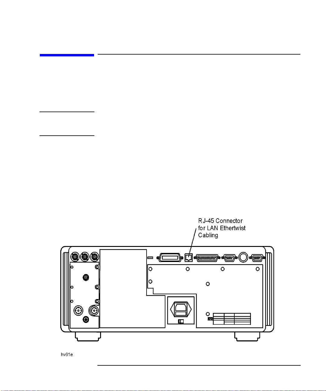
Your analyzer has an RJ-45 connector (see Figure 1-1) and connects to
your network using 10Base-T unshielded twisted pair (UTP) cabling,
also called Ethertwist. Ethertwist cables resemble standard modular
phone cables.
NOTE If your network uses ThinLAN (10Base-2), you will need to purchase an
adapter which converts the ThinLAN BNC connector to 10Base-T
Ethertwist.
To connect the analyzer to your network:
1.Turn off the analyzer.
2.Connect the Ethertwist cable from your network to the LAN
ETHERTWIST port on the rear of your analyzer.
3.Turn on the analyzer.
Figure 1-1 The LAN ETHERTWIST Port
LAN Interface Supplement 1-5
Page 17

Connecting and Configuring the Analyzer
Setting Up a Network
Setting Up a Network
If you do not already have a network, you will need to create one. A
simple network consists of a central LAN hub with multiple Ethertwist
cables, one connected to the LAN port of each network device. This is
often called a star topology, with the LAN hub at the center.
• Typical 8-port hub
HP J2610B AdvanceStack 10Base-T Hub-8U
• Typical 16-port hub
HP J2611B AdvanceStack 10Base-T Hub-16U
• Typical Ethertwist cables
92268A twisted-pair “straight-through” cable, 4 meters
92268B twisted-pair “straight-through” cable, 8 meters
92268C twisted-pair “straight-through” cable, 16 meters
92268D twisted-pair “straight-through” cable, 32 meters
92268N twisted-pair “straight-through” cable, 300 meters
To order cables , contact the nearest Agilent T ec hnologies sales or service
office. See Table 9-5 on page 9-11 for a list of sales and service offices.
Figure 1-2 Example of LAN Star Topology
1-6 LAN Interface Supplement
Page 18

Connecting and Configuring the Analyzer
Setting Up a Network
Point-to-Point Connections
It is possible to connect a single computer to a single analyzer, and avoid
using a LAN hub. T o do this, you must use a special “cross-over” cable or
adapter, which acts like a LAN hub. See “EIA/TIA 568B Wiring” on page
9-2 for wiring details. If you try to create a point-to-point connection
using a standard “straight-through” cable, it will not work. For most
applications, the use of a LAN hub is simpler, and additional devices can
be added easily.
NOTE Some commercially-available cross-over cables do not implement the
cross-over wiring required for your analyzer. Please refer to “EIA/TIA
568B Wiring” on page 9-2 and verify all connections before using cables
not made by Agilent Technologies.
NOTE Point-to-point connections may not work when connecting to older laser
printers. Older printers typically require a boot server for network use.
For a point-to-point connection with a printer, use an HP LaserJet 4 or
newer.
NOTE Point-to-point connections do not require the use of proxy servers, since
no server is present in a point-to-point network connection. To use a
point-to-point connection, first disable the use of a proxy server in your
LAN software. Refer to your software documentation for instructions
how to do this.
LAN Interface Supplement 1-7
Page 19

Connecting and Configuring the Analyzer
Configuring the Analyzer
Configuring the Analyzer
Before you configure your analyzer, you will need to contact your
network administrator to obtain the following information:
❏ an IP address for the analyzer
❏ a host name for the analyzer
❏ a gateway IP address
❏ a subnet mask
The Analyzer's IP Address and Hostname
Each device on your network must have a unique address so that all
devices can communicate simultaneously over the same network. These
unique addresses are called IP addresses, and are assigned by your
network administrator. An IP address is a set of four decimal numbers,
separated by periods, like 192.170.128.21. In this document, the term
“LAN address” refers to the IP address.
CAUTION It is important that no two devices are assigned the same IP address.
Both devices may fail to communicate on the network.
You may also receive (or request) from your network administrator a
hostname for your analyzer, like my8712.
The hostname is not required, but can be used on your computer so that
you don't have to remember the IP address. Typically, the hostname is
found in the /etc/hosts or control panel/network file on your
computer or is returned by a name server.
Your network administrator will apply for a range of IP addresses from
the Internet Network Information Center (InterNIC). InterNIC is
responsible for registering domain names and assigning TCP/IP network
numbers to networks that connect to the Internet. You may contact
InterNIC via e-mail at hostmaster@internic.net, or by accessing
their Web site at http://www.networksolutions.com.
1-8 LAN Interface Supplement
Page 20

Connecting and Configuring the Analyzer
Configuring the Analyzer
The Gateway Address
If your analyzer will be communicating with devices on different physical
networks, you may need to have your network administrator assign a
gateway IP address for you. The gateway IP address is the address of a
routing device that connects your analyzer's LAN with other LANs. Set
the gateway address to 0.0.0.0 if a gateway is not required. See “To
Configure the Analyzer” on page 1-10 to set this.
See “Subnets and Gateways” on page 8-15 for more information on
gateway addresses.
The Subnet Mask
If your analyzer will be communicating with devices on different physical
networks, you may need to have your network administrator assign a
subnet mask number for you. The subnet mask tells your analyzer
whether a remote device is on the same LAN as your analyzer. If your
analyzer is attempting to communicate with another device, the subnet
mask defines whether your analyzer needs to route communications
through the gateway. Set the subnet mask to 0.0.0.0 if a subnet mask
is not required. See “Configuring the Analyzer” on page 1-8to set this.
See “Subnets and Gateways” on page 8-15 for more information on
subnet masks.
The Ethernet Address
Y our analyzer has a unique built-in Ethernet address associated with the
LAN hardware inside it. The Ethernet address is a 48-bit number
assigned at the factory. You don’t have to know the Ethernet address to
configure and use the analyzer, unless you are using the BOOTP feature
(see “Using BOOTP” on page 1-15 for details).
LAN Interface Supplement 1-9
Page 21

Connecting and Configuring the Analyzer
LAN
LAN Port Setup
HP 871xxx IP Address
Gateway IP Address
Subnet Mask
Configuring the Analyzer
To Configure the Analyzer
1. Press to access the LAN menu.
NOTE After each of the following steps, the analyzer will prompt you to cycle
power for the new setting to take effect. It is not necessary to cycle the
power after each step. It only needs to be done once—when you are
finished entering all of the settings.
2. Press , and enter the
IP address that your network administrator assigned to your
analyzer. You may have also received a hostname (for example:
my8712). You cannot enter the hostname into your analyzer, just the
IP address. The hostname can be used on your computer so that you
don't have to remember the IP address.
3. Press , and enter the numbers assigned to
you by your network administrator. If you were not assigned a
gateway IP address, leave the setting at 0.0.0.0 (default value) to
disable gateway routing.
4. Press , and enter the numbers assigned to you by
your network administrator. If you were not assigned a subnet mask,
leave the setting at 0.0.0.0 (default value) to disable subnet
masking.
5. Once you have entered these settings, cycle the power on your
analyzer to initialize the LAN interface with these new values.
SYSTEM OPTIONS
1-10 LAN Interface Supplement
Page 22

Connecting and Configuring the Analyzer
Testing the LAN Communication
Testing the LAN Communication
You should now test communication between your computer and your
analyzer.
The ping utility is typically used to test LAN communication.
Running Ping under Windows 95
Enter the following at the command prompt of a DOS window on your
computer or workstation:
ping <IP address>
or
ping <hostname>
<IP address> is the number that was assigned by your network
administrator and was entered into your analyzer in “To Configure the
Analyzer” on page 1-10. The <hostname> is the hostname assigned to
your IP address. For example, type:
ping my8712
where my8712 is the <hostname>.
The ping utility has three common responses. If there is a valid working
connection, you should see a response similar to this:
Pinging my8712 [15.4.43.5] with 32 bytes of data:
Reply from 15.4.43.5: bytes=32 time=37ms TTL=252
Reply from 15.4.43.5: bytes=32 time=30ms TTL=252
Reply from 15.4.43.5: bytes=32 time=30ms TTL=252
Reply from 15.4.43.5: bytes=32 time=31ms TTL=252
If you see a response similar to the following, your connection may have a
problem. Refer to “Troubleshooting the Initial Connection” on page 8-3
for troubleshooting help and information.
Request timed out.
Request timed out.
Request timed out.
Request timed out.
LAN Interface Supplement 1-11
Page 23

Connecting and Configuring the Analyzer
Testing the LAN Communication
The following response is generally caused by an incorrect subnet mask
or IP address. It usually points to a software setting conflict, and does
not signify a hardware problem.
Host Unreachable.
Host Unreachable.
Host Unreachable.
Host Unreachable.
Running Ping under UNIX
The ping program is typically found in the /etc or/usr/etc directory,
so you must add the appropriate directory to your path, or type the full
path:
/etc/ping <IP address> 64 5
or
/etc/ping <hostname> 64 5
This command tells ping to send 5 packets of 64 bytes each.
The output should look similar to this:
PING hostname: 64 byte packets
64 bytes from 15.4.43.5: icmp_seq=0. time=8. ms
64 bytes from 15.4.43.5: icmp_seq=1. time=4. ms
64 bytes from 15.4.43.5: icmp_seq=2. time=4. ms
64 bytes from 15.4.43.5: icmp_seq=3. time=3. ms
64 bytes from 15.4.43.5: icmp_seq=4. time=3. ms
hostname PING Statistics
5 packets transmitted, 5 packets received, 0% packet loss
round-trip (ms) min/avg/max = 3/4/8
If you do not see any output after about 20 seconds, interrupt the ping
command using ^c (hold down the “Ctrl” key, and press “c”). Once you do
this, the ping program should provide some statistics on how many
packets were sent and received. If the statistics look like
hostname PING Statistics
4 packets transmitted, 0 packets received, 100% packet loss
there is a communications problem. Refer to “Troubleshooting the Initial
Connection” on page 8-3 for troubleshooting help and information.
1-12 LAN Interface Supplement
Page 24

Connecting and Configuring the Analyzer
LAN
Login User Setup
Add Login User
Enter
Enter
Managing User Names and Passwords
Managing User Names and Passwords
Your analyzer implements a limited form of network security using user
name and password pairs. Any remote access of the analyzer, including
Telnet or FTP access, requires a valid user name and associated
password.
A default user name and password pair is set for you prior to shipment:
User Name network
Password analyzer
NOTE You should change this user name and password if you want to use the
security features of the analyzer, since the default user name and
password is the same for all new analyzers, and is therefore public.
Constructing Valid User Names and Passwords
A valid user name must have 1 to 40 characters. A valid password must
have 8 to 40 characters.
Adding New User Names and Passwords
NOTE You can add up to seven user name/password pairs to the analyzer’s
access list.
Perform the following steps to add a new user name and password to the
access list:
1. Press .
2. Press .
3. Type the user name in the displayed dialog box.
4. Press when you are done.
5. Type the password in the displayed dialog box.
6. Press when you are done.
LAN Interface Supplement 1-13
SYSTEM OPTIONS
Page 25

Connecting and Configuring the Analyzer
Enter
LAN
Login User Setup
Delete Login User
Enter
Enter
LAN
Login User Setup
Delete All Users
LAN
Login User Setup
Display User List
Managing User Names and Passwords
7. Type the password again (to confirm the password) in the displayed
dialog box.
8. Press when you are done.
If the entries are valid, the new user name and password will be
confirmed with the following message:
User ... has been added to the list
Removing a User from the Access List
Perform the following steps to remove a user from the access list:
1. Press .
2. Press .
3. Type the user name in the dialog box that is displayed.
4. Press to confirm your entry.
5. Type the user password in the dialog box.
6. Press to confirm your entry.
If the entries are valid you should see a confirmation message displayed
on the screen:
User ... has been deleted from the list
NOTE If you forget any of the user passwords, you will have to delete all users
by pressing
SYSTEM OPTIONS
SYSTEM OPTIONS
and re-enter all user names and passwords.
Displaying the Access List
1. Press .
2. Press .
A table of the login user names will be displayed on the screen.
SYSTEM OPTIONS
1-14 LAN Interface Supplement
Page 26

Connecting and Configuring the Analyzer
Using BOOTP
Using BOOTP
BOOTP Fundamentals
The Bootstrap Protocol (BOOTP) is a simple and elegant method of
automatically distributing network information and software via the
LAN. BOOTP is built on the client-server model. The BOOTP client
configures itself using configuration information obtained from a BOOTP
server. Your analyzer has a built-in BOOTP client. The analyzer can use
BOOTP to configure itself automatically, obtaining its network
configuration information (IP address, gateway address, and subnet
mask) from a central BOOTP server over the network. On power up, the
analyzer broadcasts a request to boot from a remote server. If a BOOTP
server is available on the LAN listening for BOOTP client requests, it
transmits configuration parameters to the analyzer over the network.
The analyzer uses those parameters automatically.
BOOTP can also be used to automatically retrieve and execute an IBASIC
program at boot time. The boot file is transferred to the analyzer from
the BOOTP server using FTP or trivial file transfer protocol (TFTP). If the
transfer is successful, the file will be loaded into the analyzer’s memory
and executed. The boot file can be any valid IBASIC program.
Setting Up the BOOTP Server
To use the BOOTP client in your analyzer, you need a BOOTP server
application running on a remote UNIX system or a PC. A BOOTP server,
bootpd (BOOTP daemon), is an integral part of most UNIX operating
systems. You will need to obtain a separate BOOTP server application for
your PC. Consult your network administrator for obtaining a BOOTP
server application for your PC, and for assistance setting up a BOOTP
server.
The following steps are required to use BOOTP:
1. Assure that the analyzer and BOOTP server are not separated by a
gateway. Consult your network administrator if you are not sure.
2. Set up a BOOTP server application on a remote host (UNIX system or
PC). You will need the following information:
LAN Interface Supplement 1-15
Page 27

Connecting and Configuring the Analyzer
LAN
LAN Port Setup
Ethernet Address
LAN
BOOTP Setup
BOOTP ON off
FTP
FTP
FTP User Name
FTP Password
Timeout
Timeout
Using BOOTP
❏ The Ethernet address of the analyzer. To find out the Ethernet
address of your analyzer, press
SYSTEM OPTIONS
.
❏ An IP address for the analyzer. This address is usually assigned
by your network administrator.
❏ An optional BOOTP host name and IP address.
❏ An optional absolute (fully qualified) path to the boot file, which
includes all the directories leading to it. If you want to retrieve an
IBASIC boot program from your BOOTP server at boot time and
execute it, you must know the absolute path to the boot file. The
boot file must be accessible using FTP or TFTP.
❏ The LAN gateway address and the subnet mask.
Setting Up the BOOTP Client
Perform the following steps to set up the BOOTP client in your analyzer:
1. Press .
2. Toggle [BOOTP] to ON if needed to enable BOOTP. The softkey label
will change to .
3. Press or to select either FTP or TFTP file transfer
method. If your remote system requires a user name and password,
you must use FTP, since TFTP does not implement any user
validation.
If you select
a. Press and enter a valid user name for your
b. Press and enter a valid password for your
4. Press and enter a timeout time, in seconds, for BOOTP
requests. This value is typically between one and five seconds. The
spend transmitting BOOTP requests at boot time. If there is no
response to the first BOOTP request, then the analyzer will retransmit
SYSTEM OPTIONS
remote BOOTP host.
remote BOOTP host.
value is the number of seconds that your analyzer will
1-16 LAN Interface Supplement
Page 28

Connecting and Configuring the Analyzer
Timeout
Optional Boot Host
Optional Boot Host
Optional Boot Host
Clear Entry
Enter
Optional Boot Host
Optional File Name
Using BOOTP
a request. The analyzer will continue to retransmit requests at
exponentially increasing time intervals until it receives a response or
the value has expired.
5. Press and enter a hostname or a host IP
address if you want BOOTP requests sent to a specific remote host
only. Otherwise, the analyzer will broadcast a BOOTP request at boot
time, and will accept a response from any BOOTP server.
If you do not want to use , make sure that it
contains a null or empty string by pressing
.
NOTE If you use , you are also required to set up your
analyzer’s IP address. Refer to“To Configure the Analyzer” on page 1-10
for details on how to set up your analyzer’s IP address.
NOTE A local HOSTS file is required to specify a boot host by name. A local
HOSTS file is not required to specify a boot host by IP address. “Using a
Local HOSTS File” on page 7-11 for details about creating and using a
local HOSTS file.
NOTE You must use the UNIX-style forward slash (/) to separate names when
6. Press and enter an absolute (fully qualified)
path to the file to be loaded and executed when the analyzer boots.
For example , if your file name istest23.bas, and the path to the file
is /server5/users/testeng/prodtests, enter the following for
the absolute (fully-qualified) path name:
/server5/users/testeng/prodtests/test23.bas
you enter path names in the analyzer (the BOOTP client). You may need to
use some other character to separate names when you enter path names
in your particular BOOTP server.
LAN Interface Supplement 1-17
Page 29

Connecting and Configuring the Analyzer
Optional File Name
Optional File Name
Optional File Name
Clear Entry
Enter
LAN
BOOTP Setup
Parameters Received
Using BOOTP
Normally, your analyzer will obtain this file name from the BOOTP
server, but you can override this using . If you
do not want to use , make sure that it contains
a null string. To do that, press
NOTE You can set up your BOOTP server to select the file to download when the
analyzer boots. Consult your BOOTP server documentation or your
system administrator about setting up a BOOTPTAB file on the BOOTP
server.
Testing BOOTP
After your analyzer has been set up correctly as a BOOTP client, make
sure that the BOOTP server is also set up correctly and is running.
Consult your network administrator if you need help doing this.
Perform the steps below to verify that BOOTP works correctly:
1. Press
The following dialog box will appear:
SYSTEM OPTIONS
.
1-18 LAN Interface Supplement
Page 30
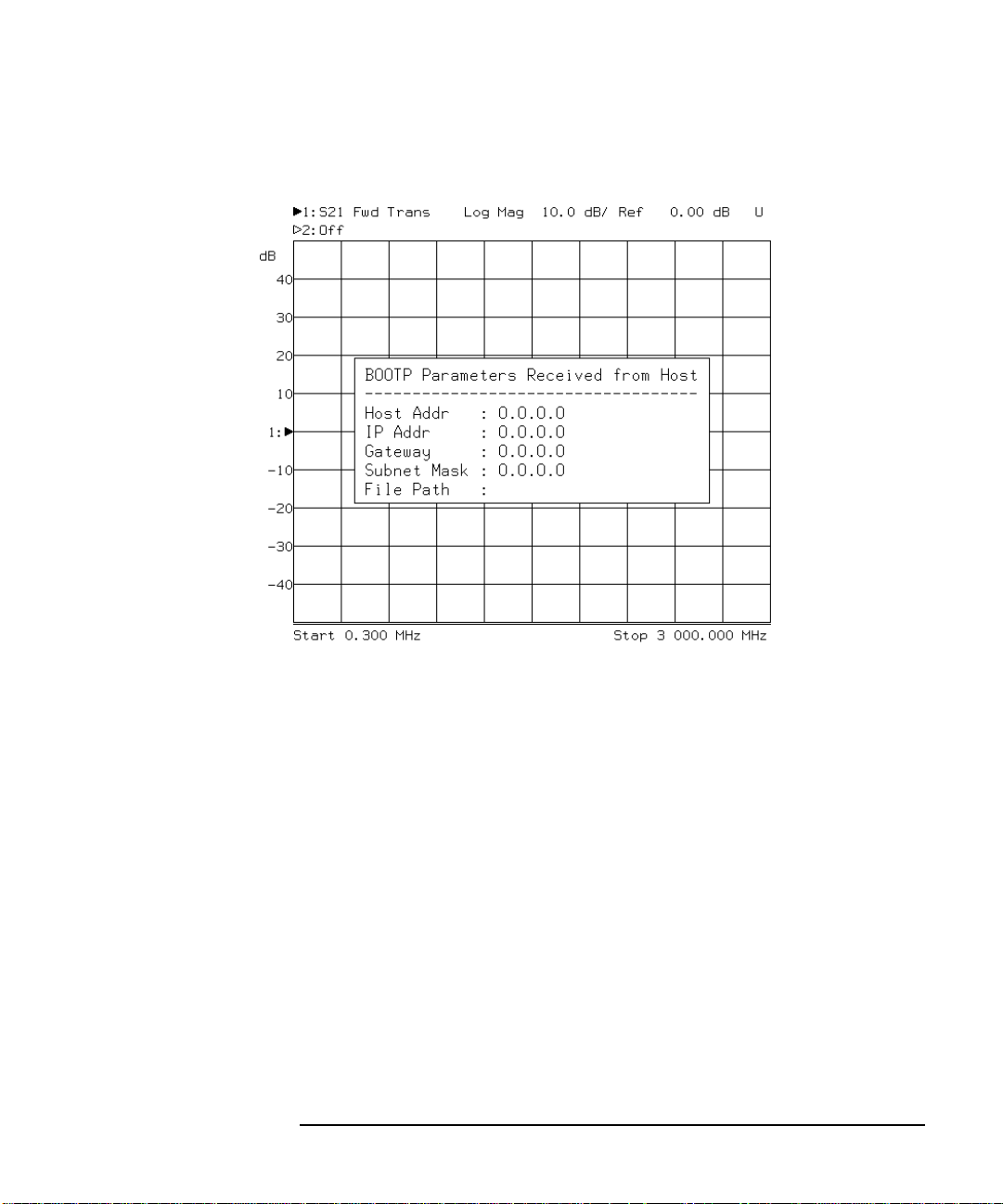
Figure 1-3 BOOTP Setup Dialog Box
Connecting and Configuring the Analyzer
Using BOOTP
The dialog box shown above displays the following information:
Host Addr the host address of the BOOTP server
IP Addr the analyzer IP address set by BOOTP process
Gateway the analyzer gateway IP address set by the BOOTP
process
Subnet Mask the subnet mask set for the analyzer by the BOOTP
process
File Path the absolute (fully-qualified) path name received
from the BOOTP server, or the [Optional File Path]
if set
Step one shows the network parameters received from the BOOTP
server. To verify that your IBASIC boot file is working correctly,
perform steps two through four.
LAN Interface Supplement 1-19
Page 31

Connecting and Configuring the Analyzer
LAN
LAN Port Setup
871xxx IP Address
Clear Entry
Enter
LAN
LAN Port Setup
Gateway IP Address
Clear Entry
Enter
LAN
LAN Port Setup
Subnet Mask
Clear Entry
Enter
Using BOOTP
2. Clear your current network configuration information.
a. Press
SYSTEM OPTIONS
.
b. Press
SYSTEM OPTIONS
.
c. Press
SYSTEM OPTIONS
.
3. Create an IBASIC file that, when run, will clearly indicate the
successful retrieval and execution of the file. Store it on the BOOTP
server. Here's an example:
10 ASSIGN @Hp8712 TO 800
20 OUTPUT @Hp8712;"DISP:ANN:TITL ON"
30 OUTPUT @Hp8712;"DISP:ANN:CLOC:MODE OFF"
40 OUTPUT @Hp8712;"DISP:ANN:TITL1:DATA 'BOOTP is here!!!'"
50 END
4. Cycle power to your analyzer. After your analyzer boots, the network
IP address, gateway address and subnet mask should be those values
provided by the BOOTP server.
If you have a boot file set up correctly, your analyzer should also
retrieve and execute your boot file. If you used the example program
above, the screen will display
BOOTP is here!!!
1-20 LAN Interface Supplement
Page 32

Connecting and Configuring the Analyzer
Setting Up LAN Features with Wizards
Setting Up LAN Features with Wizards
IBasic LAN Wizard
An IBasic LAN wizard program is included with the analyzer to assist
users in setting up the LAN features. It is located on the Example
Program Disk, part number 08714-10003, under the name lan_wiz.
Windows LAN Wizard
A Windows-based LAN wizard program is also included with the
analyzer to assist users in setting up the LAN features. It is located on
the Example Program Disk, part number 08714-10003, under the name
wiz871x.exe.
It is necessary to set up the analyzer’s IP address and SCPI socket port
number before using this program.
NOTE Example programs for the analyzer can be found in the following two
locations:
• Example Programs Disk, 8712ET/ES and 8714ET/ES (DOS format):
part number 08714-10003
• Web site http://www.agilent.com. Use the search function to find Web
pages related to 8712 and 8714 example programs and wizard
programs.
LAN Interface Supplement 1-21
Page 33

2 Accessing the Analyzer's Web
Pages
2-1
Page 34

Accessing the Analyzer's Web Pages
This page left intentionally blank.
2-2 LAN Interface Supplement
Page 35

Accessing the Analyzer's Web Pages
About This Chapter
About This Chapter
Your analyzer has built-in web pages that are accessible with a web
browser such as Netscape Navigator or Microsoft® Internet Explorer.
These web pages contain links to general product information, selected
on-line documentation, benchmarks, information about your analyzer,
and a list of Agilent Technologies offices . You can also e-mail us with your
comments and feedback on the Agilent Technologies 87xx family of
analyzers.
Before you can access your analyzer with a web browser, you need to
connect and configure your analyzer as described in Chapter 1,
“Connecting and Configuring the Analyzer.”
If your analyzer is directly connected to a PC, without the use of a hub or
a larger network, then you probably need to disable the proxy server in
the browser. This is because most web browsers are configured to use
proxy servers for accessing web pages. If your analyzer is directly
connected to your computer, your computer cannot find the proxy server.
If you are communicating to your analyzer over a LAN, then the proxy
setting can be left as it is.
LAN Interface Supplement 2-3
Page 36

Accessing the Analyzer's Web Pages
Accessing the Analyzer with Your Web Browser
Accessing the Analyzer with Your Web
Browser
To access your analyzer, start your web browser and connect to
http://<hostname>, where <hostname> is the hostname that has
been assigned to the IP address of your analyzer. If you are making a
connection to the analyzer without using a domain name system (DNS)
server, you can use http://<IP address>, where <IP address> is
the IP address of your analyzer. You can also use the IP address form
when using a DNS server.
When you are connected to your analyzer, a web page will appear with
the following information links:
• Get a current screen snapshot
• Control the Analyzer with SCPI Commands
• Examine your analyzer's configuration
• Browse selected product documentation
• Review the Product Summary
• Other links
Click on the hyperlinks (any underlined words) to browse through the
analyzer's pages. See Figure 2-1.
The rest of this chapter explains some of the areas you can browse in
further detail.
2-4 LAN Interface Supplement
Page 37

Figure 2-1 Analyzer Web Page
Accessing the Analyzer's Web Pages
Accessing the Analyzer with Your Web Browser
LAN Interface Supplement 2-5
Page 38

Accessing the Analyzer's Web Pages
Color Options
Inverse Video
Accessing the Analyzer with Your Web Browser
Screen Snapshot
Clicking on Get a current screen snapshot shows an exact copy of your
analyzer's current screen image. Use your web browser's “reload” or
“refresh” function to get the most current screen image.
CAUTION The screen image takes a few seconds to load. Do not push any buttons
on the analyzer or send any programming commands to it while the
snapshot is loading, or an inaccurate image may result.
NOTE Before capturing the screen image with your web browser, you may wish
to customize the look of the image using the menu on
your analyzer. (See your analyzer's User's Guide for more information.)
In particular, you may want to choose to create a white
background, especially if you plan to print the page from your web
browser. See Figure 2-2.
2-6 LAN Interface Supplement
Page 39

Figure 2-2 Screen Snapshot
Accessing the Analyzer's Web Pages
Accessing the Analyzer with Your Web Browser
LAN Interface Supplement 2-7
Page 40

Accessing the Analyzer's Web Pages
Accessing the Analyzer with Your Web Browser
Control the Analyzer with SCPI Commands
Clicking on Control the Analyzer with SCPI Commands launches a Java
applet. This applet creates a command-entry dialog box. You can control
your analyzer over the LAN by entering SCPI commands in this dialog
box. See Figure 2-3. Commands or queries are sent to the analyzer by
entering the SCPI mnemonic in the SCPI Command: area, and the
response from the analyzer is displayed in the Response Messages: area.
Example commands are provided on this web page as well as a link to
the SCPI command reference.
It may be helpful to save frequently-sent SCPI command strings in a
separate ASCII file. These commands can then be cut and pasted from
the ASCII file into the command line of the dialog box, and edited, if
necessary, before sending them to the analyzer.
NOTE Java is a powerful, cross-platform programming language developed by
Sun Microsystems. See http://www.javasoft.com for more details.
2-8 LAN Interface Supplement
Page 41

Figure 2-3 SCPI Command Screen
Accessing the Analyzer's Web Pages
Accessing the Analyzer with Your Web Browser
LAN Interface Supplement 2-9
Page 42

Accessing the Analyzer's Web Pages
Service
Instrument Info
Accessing the Analyzer with Your Web Browser
Analyzer Configuration
Clicking on Examine your analyzer's configuration brings up a screen of
information that is equivalent to pressing
on the analyzer. This screen shows the
model and serial number of your analyzer, the firmware revision,
installed options, and the amount of memory.
SYSTEM OPTIONS
Product Documentation
This section provides selected portions of your analyzer's documentation
on-line, as well as benchmark information and information about
product upgrades and options.
The following list shows the links currently available on this page:
• Optimizing your Measurements
• Accessing Built-in Disks
• Controlling I/O Ports
• Accessing the Analyzer's file system via the LAN
• Accessing the Dynamic Data Disk via the LAN
• Controlling the Analyzer via the LAN
• Agilent Technologies 871xE SCPI command reference
• IEE 488.2 common commands
• Product Upgrades and Options
• Transfer Speeds using GPIB
• Transfer Speeds using LAN
• Printing Speed
• List of printed manuals
If there are additional portions of the analyzer's documentation that you
think would be helpful to have on-line, please contact us via e-mail. Click
on “Contact Agilent Technologies” and “Send us your feedback!” from
your analyzer's web page.
2-10 LAN Interface Supplement
Page 43

Accessing the Analyzer's Web Pages
Accessing the Analyzer with Your Web Browser
Product Overview
The links in this area provide generic information about the Agilent
Technologies 871xE family of analyzers. New features, compatibility
issues, and available options are included here.
Other Links
At the bottom of every web page in the analyzer, you'll find the following
links:
• Top takes you to the top of the current
page.
• Search takes you to the “Product
Documentation” page.
• Contact Agilent Technologies takes you to a page that provides
links to Agilent Technologies web
sites, and gives you the opportunity
to provide Agilent with feedback on
your analyzer and its documentation.
• Upgrade Firmware takes you to a page that helps you
download firmware from Agilent
Technologies websites.
• VXI plug&play Driver takes you to a page that helps you
download free VXI plug&play drivers
from Agilent Technologies websites.
• Copyright takes you to copyright information.
LAN Interface Supplement 2-11
Page 44

3 Printing
3-1
Page 45

Printing
About This Chapter
About This Chapter
Your analyzer can print directly to an HP LaserJet printer on your
network. In order to print to a LAN printer, your analyzer must be
communicating on the network. Refer to Chapter 1, “Connecting and
Configuring the Analyzer ,” on page 1-1 if you have not yet connected and
configured your analyzer.
Compatible Printers
The HP LaserJet 4 and HP LaserJet 5 families of printers are compatible
with your analyzer for printing directly via a point-to-point connection or
over your network. These newer printers allow you to enter the printer's
IP address directly from the analyzer front panel and do not require a
boot server computer. Your printer should have a JetDirect LAN card
installed.
NOTE Some older printers, such as an HP LaserJet III, do not allow you to
enter an IP address from the analyzer front panel. They require a boot
server computer on the network that configures (sets) the printer's IP
address.
3-2 LAN Interface Supplement
Page 46

Printing
Configuring the Printer
Configuring the Printer
Refer to your printer's documentation for instructions on how to set up
your printer for LAN usage. Typically, you will need to contact your
network administrator to assign a unique IP address for your printer.
Your printer software will configure the printer with the assigned IP
address each time it is turned on.
LAN Interface Supplement 3-3
Page 47

Printing
Select Copy Port
Select
Configuring the Analyzer for Printing to a LAN Printer
Configuring the Analyzer for Printing to
a LAN Printer
To set up your analyzer to print to a LAN printer:
1. Press .
2. Use the front panel knob, or the keys to highlight the
LaserJet LAN printer in the table. See Figure 3-1.
3. Press . See Figure 3-1.
Figure 3-1 Selecting and Configuring the LAN Printer
HARDCOPY
3-4 LAN Interface Supplement
Page 48

Printing
LAN Printr IP Addr
Clear Entry
Prior Menu
Define PCL5
Define Hardcopy
Define PCL5
Color
Start
Configuring the Analyzer for Printing to a LAN Printer
4. Press . Enter the IP address of the network
printer you wish to use. Use the key to clear the
current or default setting, and then enter the IP address using the
analyzer's numeric keypad. (Y ou can also use a keyboard connected to
the rear panel DIN KEYBOARD connector to enter the IP address.)
5. Press and use the key to set up the
printer configuration, and use the key to define
the output. See your analyzer's User's Guide for information on
configuring printers and defining output.
NOTE You can print color screen dumps if you send the output to an HP Color
LaserJet or HP Color LaserJet 5 printer. Press .
6. After you have completed the previous steps, you can send hardcopy
to your LAN printer by simply pressing .
HARDCOPY
LAN Interface Supplement 3-5
Page 49

Printing
If You Have Trouble Printing
If You Have Trouble Printing
• Make sure the analyzer's LAN IP address has been set
(see “The Analyzer's IP Address and Hostname” on page 1-8).
• Make sure the printer is configured properly. Refer to your printer's
documentation or your network administrator.
• V erify the LAN connection to the printer using the analyzer's built-in
ping diagnostic utility (see “Troubleshooting the Initial Connection”
on page 8-3).
3-6 LAN Interface Supplement
Page 50

4 Accessing the Analyzer's File
System Using FTP
4-1
Page 51

Accessing the Analyzer's File System Using FTP
About This Chapter
About This Chapter
This chapter shows you how to access the analyzer's file system using file
transfer protocol (FTP). This chapter provides two simple examples: one
example copies a file to the analyzer from your computer, and the other
retrieves a file from the analyzer. The last section of this chapter
contains a summary of commonly used ftp commands.
NOTE It is important to distinguish among the several uses of the letters ftp:
FTP File Transfer Protocol: a standardized service that
provides methods to remotely transfer files among
different computers and operating systems. The FTP
service is implemented by many different computer
applications, including programs named ftp.
ftp The name given to many different computer programs,
each implementing File Transfer Protocol (FTP).
Programs with the name ftp are available for
Windows 95, Windows NT, and Unix, for example.
ftp The letters you type to start a program named ftp.
This chapter assumes that your analyzer is physically connected to your
local area network. If it is not connected, refer to “Connecting the
Analyzer to the LAN” on page 1- 5 for information on how to connect the
system.
When you access the analyzer, you will have read and write access to the
analyzer's file system (except for some files in the dynamic “data” disk,
which are described in “The Dynamic Data Disk” on page 5- 2).
CAUTION Avoid having more than one FTP session access your analyzer
simultaneously. Files may be corrupted if both sessions attempt to use
the same file at the same time.
This caution also applies to file system access performed via SCPI
commands using LAN, GPIB, or IBASIC.
4-2 LAN Interface Supplement
Page 52

Accessing the Analyzer's File System Using FTP
Using FTP to Access the Analyzer
Using FTP to Access the Analyzer
If you are using a UNIX workstation, you have built-in networking
software that includes ftp. The same is true if you are operating under
Windows 95. If you are operating under Windows 3.1, you will need to
have additional networking software that includes ftp.
NOTE There are versions of FTP programs available with a graphical user
interface (GUI). See “Using GUI FTP Software” on page 4- 10 for
information on using these types of programs.
To access the analyzer's file system using FTP and the ftp utility
1. Enter the following command on your computer or workstation:
ftp <hostname>
or
ftp <IP address>
For example, type
ftp my8712
or
ftp 223.15.2.44
2. When the connection is made, you will be prompted for a login name
and password. Enter your user name and password. The default login
name is network, and the default password is analyzer. See
“Managing User Names and Passwords” on page 1- 13.
3. You should now have a prompt on your computer display that looks
like this:
ftp>-
4. Type dir at the prompt. Your computer display should return
something that looks like this:
200 Port command okay
150 Opening data connection for LIST /
drwx
------
drwx
------
drwx
------
drwx
------
226 File sent OK
2 root sys 1024 Oct 9 int
2 root sys 1024 Oct 9 nvram
2 root sys 1024 Oct 9 ram
2 root sys 1024 Oct 9 data
LAN Interface Supplement 4-3
Page 53

Accessing the Analyzer's File System Using FTP
Using FTP to Access the Analyzer
The first character in the first field indicates the entry type. A “d”
indicates that the entry is a directory. A “–” indicates that the entry is
an ordinary file.
The next nine characters in the first field are interpreted as three sets
of three bits each. The first three bits identify access permissions for
the user (rwx). The second three bits are left blank. The final three
bits identify the file type:
• A — archive file
• H — hidden file
• S — system file
You can read and write files to:
• int — a DOS-formatted floppy disk in the analyzer's 3.5” floppy
disk drive
• nvram — the analyzer's internal non-volatile memory
• ram — the analyzer's internal volatile memory
The data directory is a dynamic data disk with files that are linked
directly to analyzer operations. See “The Dynamic Data Disk” on
page 5- 2 for information on accessing and using this directory.
5. Use the examples in this chapter to copy a file to the analyzer and to
retrieve a file from the analyzer. Also see “Commonly Used FTP
Commands” on page 4- 8.
4-4 LAN Interface Supplement
Page 54

Accessing the Analyzer's File System Using FTP
Select Disk
Non-Vol RAM Disk
Prior Menu
Programs
Recall Program
Run
Using FTP to Access the Analyzer
Example 1: Copying a File to the Analyzer
You can copy files from your computer to your analyzer . For instance, you
may want to develop an IBASIC program on your computer and then
copy it to the analyzer so that you can run it from the front panel of the
analyzer.
This example copies a file, “ib_prog”, from your computer to the
analyzer's nvram disk:
1. On your computer or workstation change directories to the directory
that contains the file “ib_prog.”
2. On your computer or workstation access the analyzer by typing ftp
<hostname>. Enter your user name and password. For example, type
ftp my8712
user name
password
where my8712 is the <hostname>, user name is your login name,
and password is your user password. The username and password
pair must be one of the entries in the analyzer’s access list. Refer to
“Managing User Names and Passwords” on page 1- 13 for details.
CAUTION Binary files can be corrupted if you attempt to transfer them in “ascii”
3. Change to the non-volatile RAM disk in the analyzer by typing
cd nvram at the ftp prompt.
4. Specify the type of file you will be transferring by typing either
binary or ascii at the ftp prompt. For this example, use ascii.
mode.
5. Type put ib_prog at the ftp prompt.
6. Type bye at the ftp prompt to exit ftp.
You can now recall and run the program from the front panel of your
analyzer.
1. Press .
2. Press . Use the front panel knob to
highlight the IB_PROG file.
3. Press .
LAN Interface Supplement 4-5
SAVE RECALL
Page 55

Accessing the Analyzer's File System Using FTP
Using FTP to Access the Analyzer
NOTE You can also download and automatically run IBASIC programs by
accessing the data disk. See “Copying an IBASIC Program to or from the
Analyzer” on page 5- 7.
NOTE When copying files from a UNIX environment to the analyzer, files that
do not meet the DOS file-naming criteria (no more than eight (8)
characters in filename, with no more than three (3) characters in
extension) will be truncated to comply. For example, if you copy a file
from UNIX named “ibasic_program.abcd”, it will appear as “ibasic_p.abc”
on the analyzer. There will be no indication from ftp that this has
occurred.
Example 2: Retrieving a File from the Analyzer
You can copy files from your analyzer to your computer . For instance, you
may want to retrieve saved measurement data from your analyzer (or a
group of analyzers) for statistical analysis on your computer. In another
scenario, you may have automated your measurement system using an
IBASIC program to save data or instrument states to the analyzer's
RAM disk. Your remote computer could asynchronously copy and delete
files from the RAM disk, back up data, and prevent the RAM disk from
filling up.
You may also want to copy instrument states and calibrations to your
computer as a backup, eliminating the need for backups on floppy disks.
Analyzer files can also be saved to a remote computer using NFS (see
Chapter 7, “Using the Network File System (NFS),” on page 7-1).
This example copies a file “STATE2.STA” from your analyzer's nvram
disk to a directory on your computer or workstation.
1. On your computer or workstation access the analyzer by typing ftp
<hostname>. Enter your user name and password. For example, type
ftp my8712
user name
password
where my8712 is the <hostname>, user name is your login name,
and password is your user password.
4-6 LAN Interface Supplement
Page 56

Accessing the Analyzer's File System Using FTP
Using FTP to Access the Analyzer
2. Change to the non-volatile RAM disk in the analyzer by typing
cd nvram at the ftp prompt.
3. If necessary, use the lcd command to change the local directory on
your computer where you want to put the file. For example: type
lcd /users/myname/871x_data.
4. Specify the type of file you will be transferring by typing either
binary or ascii at the ftp prompt.
CAUTION Binary files can be corrupted if you attempt to transfer them in “ascii”
mode. For this example, use binary.
5. Type get state2.sta at the ftp prompt.
6. Type bye at the ftp prompt to exit ftp.
7. Verify the file was copied by listing the contents of the directory it was
copied to.
LAN Interface Supplement 4-7
Page 57

Accessing the Analyzer's File System Using FTP
Commonly Used FTP Commands
Commonly Used FTP Commands
The exact commands you use within ftp depend on the software. If you
are not familiar with your ftp software, type “?” or “help” at the ftp
prompt to see a list of commands.
The following table provides a list and brief description of some
commonly used ftp commands. See “The FTP Command” on page 9- 6
for a summary of ftp.
4-8 LAN Interface Supplement
Page 58

Accessing the Analyzer's File System Using FTP
Commonly Used FTP Commands
ftp Commands
Command Description
ascii Sets the file transfer type to ASCII.
binary Sets the file transfer type to binary.
bye Closes the connection to the host and exits ftp.
cd remote_directory Sets the working directory on the host to remote_directory.
delete remote_file Deletes remote_file or empty remote_directory.
dir
[remote_directory]
get remote_file
[local_file]
help Provides a list of ftp commands.
help command Provides a brief description of command.
lcd [local_directory] Sets the local working directory to local_directory.
ls
[remote_directory]
mget remote_file
[local_file]
mput local_file
[remote_file]
put local_file
[remote_file]
Lists the contents of the specified remote_directory. If
remote_directory is unspecified, the contents of the current
remote directory are listed.
Copies remote_file to local_file. If local_file is unspecified,
ftp uses the remote_file name as the local_file name.
Lists the contents of the specified remote_directory. If the
remote_directory is unspecified, the contents of the current
remote directory are listed.
Copies remote_file to the local system. If globbing is
enabled, globbing metacharacters are expanded. If local_file
is unspecified, ftp uses the remote_file name as the local_file
name.
Copies local_file to remote file. If remote_file is unspecified,
ftp uses the local_file name as the remote_file name. If
globbing is enabled, globbing characters are expanded.
Copies local_file to remote file. If remote_file is unspecified,
ftp uses the local_file name as the remote_file name.
quit Closes the connection to the host and exits ftp.
LAN Interface Supplement 4-9
Page 59

Accessing the Analyzer's File System Using FTP
Using GUI FTP Software
Using GUI FTP Software
There are versions of FTP programs available with a graphical user
interface (GUI). These programs can make transferring files between the
analyzer and your PC a simple “drag and drop” operation.
NOTE The procedures in this section were developed using Reflection™ FTP for
Windows NT. They are intended as examples only. Other GUI FTP
software may not be able to understand the analyzer's directory format,
and will probably have different steps.
Example: Transferring Files between the Analyzer and Your PC
This example copies a file, “ib_prog”, from your computer to the
analyzer's nvram disk.
1. Start the Reflection™ FTP program and set the program options as
follows:
• Set View to Split Window. (View both the command window and
the normal window.)
• Under the Options menu, set Server Directory Format to
Automatic Server Determination.
2. Type your analyzer's hostname in the Server Name box.
3. Click on Open.
4. Enter your user name.
5. Enter your password.
6. To change to the non-volatile RAM disk in the analyzer, click inside
the command window and then type cd nvram at the ftp> prompt.
Y ou can also double-clic k on a directory to expand the directory listing
and access the files in that directory.
7. Use the Client side of the window to change directories on your PC to
the directory that contains the file “ib_prog”.
8. Click on the file “ib_prog” and “drag” it over to the Server side of the
window and “drop” it.
4-10 LAN Interface Supplement
Page 60

Accessing the Analyzer's File System Using FTP
Using GUI FTP Software
9. The file has been transferred to the non-volatile RAM disk on your
analyzer.
10.To drag and drop multiple files, hold down the Ctrl key on your PC
while selecting files with the mouse. When you drag and drop, your
entire selection will be transferred to the analyzer.
11.You can also transfer files from the analyzer to your computer by
dragging files in the other direction.
CAUTION Be sure to use the appropriate file transfer method (binary or ASCII) for
the file(s) you are transferring. If you are transferring files to or from the
analyzer's dynamic data disk, check Table 5-1 on page 5-2 for file types.
NOTE In an ftp session, your analyzer is configured as an ftp server, while your
computer is an ftp client. Your analyzer cannot act as an ftp client. This
means that you cannot type ftp from the analyzer’s prompt. You can
start an ftp session from IBASIC, but that will still configure the
analyzer as the ftp server.
LAN Interface Supplement 4-11
Page 61

5 Accessing the Analyzer's
Dynamic Data Disk
5-1
Page 62

Accessing the Analyzer's Dynamic Data Disk
The Dynamic Data Disk
The Dynamic Data Disk
Your analyzer has an ftp directory called “data,” which is a dynamic data
disk. The files in this directory trigger analyzer operations. For example,
you can put an instrument state into this directory and the analyzer will
automatically recall this state. You can do the same with an IBASIC
program: copy it to the analyzer's data directory and it will automatically
run. You can also transfer a screen-image file from the analyzer in either
GIF, PCX, or HP-GL format.
The following files make up the contents of the dynamic data disk:
Table 5-1 Contents of the Dynamic Data Disk
File File Type Description
readme.txt ASCII This file contains a brief description of each file in this
directory.
state.sta
1
binary This file contains the analyzer's current instrument
state settings. Instrument state settings consist of all
the stimulus and response parameters that set up the
analyzer to make a specific measurement including
markers, limit lines, and memory traces. Instrument
state information is saved and recalled for both
measurement channels. You can either retrieve this
information from the analyzer, or you can put another
analyzer's instrument state information into this file,
which will cause the analyzer to immediately enter the
new instrument state.
cal.sta
1
binary This file contains the analyzer's current calibration
and instrument state settings. The measurement
calibration information is the measurement correction
data that the analyzer creates when you make a
calibration. Measurement calibration information is
saved and recalled for both measurement channels.
You can either retrieve this information from the
analyzer, or you can put another analyzer's calibration
and instrument state information into this file, which
will cause the analyzer to immediately enter the new
cal and instrument state.
5-2 LAN Interface Supplement
Page 63

Accessing the Analyzer's Dynamic Data Disk
File File Type Description
The Dynamic Data Disk
data.sta
2
binary This file contains the measurement data for both
measurement channels. You can either retrieve this
information from the analyzer, or you can put data
trace information from another analyzer into this file.
tset_cal.cal
1
binary For use with multiport test sets only. This file contains
the test set calibration data that currently resides on
the analyzer's non-volatile RAM disk. You can either
retrieve this information from the analyzer, or you can
put test set calibration data into this file.
prog.bas
2
ASCII This file contains the currently loaded IBASIC
program. You can either retrieve the program that is
currently in this file, or copy a new program to this file.
prog_run.bas
2
ASCII This file accepts a copy of an IBASIC program, copies it
to prog.bas, and immediately runs the program.
prog_run.scp
2
ASCII This file accepts a copy of a file containing SCPI
commands and immediately executes the commands.
screen.hgl
3
ASCII This file contains the current screen image in HP-GL
format. It is available for uploading to a file on your
computer.
screen.gif binary This file contains the current screen image in GIF
format. It is available for uploading to a file on your
computer.
screen.pcx
3
screen_m.hgl
screen_m.pcx
binary This file contains the current screen image in PCX
format. It is available for uploading to a file on your
computer.
3
ASCII This file contains the current screen image, as well as
the current softkey menu, in HP-GL format. It is
available for uploading to a file on your computer.
4
binary This file contains the current screen image, as well as
the current softkey menu, in PCX format. It is
available for uploading to a file on your computer.
LAN Interface Supplement 5-3
Page 64

Accessing the Analyzer's Dynamic Data Disk
The Dynamic Data Disk
File File Type Description
screen_m.gif
4
binary This file contains the current screen image, as well as
the current softkey menu, in GIF format. It is available
for uploading to a file on your computer.
parm_all.txt
5
ASCII This file contains a listing of all of the instrument's
operating parameters in ASCII text format.
5
parm_screen.txt
ASCII This file contains the information in the current
operating parameters screen in ASCII text format.
trace1.prn
6
ASCII This file contains the measurement channel 1
measurement data in ASCII spreadsheet format.
trace2.prn
6
ASCII This file contains the measurement channel 2
measurement data in ASCII spreadsheet format.
trace1.s1p
6
ASCII This file contains the measurement channel 1
measurement data in Touchstone format.
trace2.s1p
6
ASCII This file contains the measurement channel 2
measurement data in Touchstone format.
1. See “Saving and Recalling Analyzer States” on page 5-5 for information on how to
use this file.
2. See “Copying Programs to and from the Analyzer” on page 5-7 for information on
how to use this file.
3. See “Copying a Screen Image to a Local File” on page 5-10 for information on how
to use this file.
4. See “Copying a Screen Image to a Local File” on page 5-10 for information on how
to use this file.
5. See “Copying Instrument Parameters in ASCII Text Format” on page 5-13 for
information on how to use this file.
6. See “Retrieving Measurement Data in ASCII Format” on page 5-14 for information
on how to use this file.
5-4 LAN Interface Supplement
Page 65

Accessing the Analyzer's Dynamic Data Disk
Saving and Recalling Analyzer States
Saving and Recalling Analyzer States
This section describes how to use the state.sta, cal.sta, and
data.sta files that reside in the data directory of the analyzer. See
Table 5-1 on page 5-2 for a brief description of each of these files.
You may have a particular instrument state set up on an analyzer and
would like to set up that state on one or more additional analyzers. T o do
this you should do the following:
1. On your computer or workstation, access the analyzer by typing ftp
<hostname>. Enter your user name and password. For example, type
ftp my8712
user name
password
where my8712 is the <hostname>, user name is your login name,
and password is your user password. See “Managing User Names
and Passwords” on page 1-13 for instructions on how to do this.
2. Type cd data at the ftp prompt.
3. Type dir at the ftp prompt to see the listing of files in this directory,
as well as a short description of each file.
4. Type binary at the ftp prompt to specify a binary file transfer.
5. Type get state.sta at the prompt to copy the current instrument
state file from the analyzer to your computer.
6. Close the connection and exit ftp by typing bye or quit at the
prompt.
7. Now you can put the instrument state into a different analyzer. On
your computer or workstation, access the analyzer by typing ftp
<hostname>. Enter your user name and password. For example, type
ftp my8712
user name
password
where my8712 is the <hostname>, user name is your login name,
and password is your user password.
LAN Interface Supplement 5-5
Page 66

Accessing the Analyzer's Dynamic Data Disk
Saving and Recalling Analyzer States
8. Type cd data at the ftp prompt.
9. Type put state.sta at the ftp prompt. This copies the contents of
the state.sta file from your computer to the new analyzer you are
connected to. The new analyzer will immediately reinitialize itself
with the new instrument state.
The above procedure can be performed with the cal.sta and data.sta
files as well.
CAUTION When transferring *.sta files between instruments with different
model numbers and/or option configurations, it is possible that some
instrument state settings will not be compatible. For example, if you try
to put an instrument state with a stop frequency of 3 GHz into an
Agilent Technologies 8712ET/ES, the instrument will limit the frequency
to 1.3 GHz (its high frequency limit). When you transfer this file over ftp,
you will not receive any warning or indicator that this has occurred.
NOTE It is possible to have saved an instrument state file from the front panel
of the analyzer that contains not only the instrument state settings, but
the current calibration and measurement data as well. Putting this one
file into the state.sta file will cause the analyzer to recall instrument
state, cal state, and measurement data.
NOTE When copying files from a UNIX environment to the analyzer, files that
do not meet the DOS file-naming criteria (no more than eight [8]
characters in filename, with no more than three [3] characters in
extension) will be truncated, and will not generate an error message. F or
example, if you copy a file from UNIX named "ibasic_program.abcd", the
destination file name will be ibasic_p.abc.
5-6 LAN Interface Supplement
Page 67

Accessing the Analyzer's Dynamic Data Disk
Copying Programs to and from the Analyzer
Copying Programs to and from the
Analyzer
This section describes how to use the prog.bas, prog_run.bas, and
prog_run.scp files that reside in the data directory of the analyzer . See
Table 5-1 on page 5-2 for a brief description of each of these files.
TIP Refer to Chapter 6, “Controlling the Analyzer via the LAN” for
information on controlling the analyzer from a computer, and how to
interact with an IBASIC program running in the analyzer.
Copying an IBASIC Program to or from the Analyzer
You can create IBASIC programs on your computer and copy them to
your analyzer . Conversely, you can retrieve a copy of the currently loaded
IBASIC program from your analyzer to your computer. From there you
might want to copy it into another analyzer, or edit it.
To copy an IBASIC program file named "ib_prog" to the analyzer:
1. On your computer or workstation, access the analyzer by typing ftp
<hostname>. Enter your user name and password. For example, type
ftp my8712
user name
password
where my8712 is the <hostname>, user name is your login name,
and password is your user password. See “Using FTP to Access the
Analyzer” on page 4-3 for instructions on how to do this.
2. Type cd data at the ftp prompt.
3. Type put ib_prog prog.bas at the prompt to put a copy of your
program into the analyzer.
4. Close the connection and exit ftp by typing bye or quit at the
prompt.
LAN Interface Supplement 5-7
Page 68

Accessing the Analyzer's Dynamic Data Disk
IBASIC
Run
Copying Programs to and from the Analyzer
5. To run your IBASIC program, press
on the analyzer.
NOTE You can eliminate this last step, and have your program run
automatically by using the dynamic data disk file named
prog_run.bas. See “Copying and Running a Program with One
Command” on page 5-9.
To copy the currently loaded IB ASIC program from your analyzer to your
computer:
1. On your computer or workstation, access the analyzer by typing ftp
<hostname>. Enter your user name and password. For example, type
ftp my8712
user name
password
where my8712 is the <hostname>, user name is your login name,
and password is your user password. See “Using FTP to Access the
Analyzer” on page 4-3 for instructions on how to do this.
2. Type cd data at the ftp prompt.
3. Type dir at the ftp prompt to see the listing of files in this directory,
as well as a short description of each of them.
SYSTEM OPTIONS
4. Type get prog.bas at the prompt to retrieve the current IBASIC
program file from the analyzer. This copies the program file prog.bas
to your computer. You may want to give the file a unique name on
your local computer by typing something like this:
get prog.bas newfile
5. Close the connection and exit ftp by typing bye or quit at the
prompt.
5-8 LAN Interface Supplement
Page 69

Accessing the Analyzer's Dynamic Data Disk
Copying Programs to and from the Analyzer
Copying and Running a Program with One Command
You can create an IBASIC program or a file with a list of SCPI
commands on your computer, and then copy and automatically run it by
using the prog_run.bas and prog_run.scp files.
To copy the IBASIC program ib_prog to the analyzer and immediately
run it, follow the instructions below:
1. On your computer or workstation, access the analyzer by typing ftp
<hostname>. Enter your user name and password. For example, type
ftp my8712
user name
password
where my8712 is the <hostname>, user name is your login name,
and password is your user password. See “Using FTP to Access the
Analyzer” on page 4-3 for instructions on how to do this.
2. Type cd data at the ftp prompt.
3. Type put ib_prog prog_run.bas at the prompt. This copies your
program to the analyzer and immediately runs it.
4. You can also copy a file with a list of SCPI commands to the
prog_run.scp data file and the commands will be executed
immediately. See your analyzer's Programmer's Guide for a list of
SCPI commands.
The file you copy to "prog_run.scp" should simply be a list of SCPI
commands. Following is an example file containing SCPI commands:
SENS1:FUNC 'XFR:POW:RAT 2,0';DET NBAN;*WAI
CALC1:MARK:FUNC MAX
DISP:WIND1:TRAC:Y:AUTO ONCE
These commands set the analyzer to measure transmission, place a
marker on the maximum point, and then set the measurement trace
to autoscale mode.
NOTE Avoid the use of queries, as there is no way to read back the analyzer's
response.
LAN Interface Supplement 5-9
Page 70

Accessing the Analyzer's Dynamic Data Disk
Copying a Screen Image to a Local File
Copying a Screen Image to a Local File
This section describes how to copy a screen image from the analyzer to a
file on your computer.
To copy a screen image to your computer
1. On your computer or workstation, access the analyzer by typing ftp
<hostname>. Enter your user name and password. For example, type
ftp my8712
user name
password
where my8712 is the <hostname>, user name is your login name,
and password is your user password. See “Using FTP to Access the
Analyzer” on page 4-3 for instructions on how to do this.
2. Type cd data at the ftp prompt.
3. Type dir at the ftp prompt to see the listing of files in this directory.
4. Type binary or image at the ftp prompt to specify a binary transfer.
5. Decide which screen image file you want to retrieve and then use the
get command to transfer it to your computer. For example, type
get screen.pcx image.pcx to retrieve the current screen image
in PCX format, and place it into a file named image.pcx on your
computer.
NOTE The appearance of the image you retrieve will depend on the selections in
the Define Hardcopy menu on your analyzer, as well as the file you
choose to retrieve from the data directory. For example, Figure 5-1 was
retrieved with the "screen.hgl" file, using the analyzer's default hardcopy
mode, which includes the measurement graph and the marker table.
Figure 5-2 was retrieved with the analyzer's hardcopy mode defined as
Graph Only, using the "screen_m.hgl" file. Figure 5-2 also includes the
analyzer’s softkeys. See Table 5-1 on page 5-2 for the filenames of screen
images.
5-10 LAN Interface Supplement
Page 71

Accessing the Analyzer's Dynamic Data Disk
Copying a Screen Image to a Local File
Figure 5-1 Screen Image with Marker Table Shown
LAN Interface Supplement 5-11
Page 72

Accessing the Analyzer's Dynamic Data Disk
Copying a Screen Image to a Local File
Figure 5-2 Screen Image without Marker Table
5-12 LAN Interface Supplement
Page 73

Accessing the Analyzer's Dynamic Data Disk
Operating Parameters
Copying Instrument Parameters in ASCII Text Format
Copying Instrument Parameters in
ASCII Text Format
This section describes how to use the parm_all.txt and
parm_screen.txt files that reside in the data directory of the analyzer.
See Table 5-1 on page 5-2 for a brief description of each of these files.
Instrument parameters can be viewed on the analyzer by pressing
SYSTEM OPTIONS
information are available (the exact number depends upon your model
number and option configuration). These screens describe all the current
settings and configurations of the analyzer. You can copy all of these
screens using "parm_all.txt," or just the current screen with
"parm_screen.txt" to an ASCII file on your computer.
To copy instrument operating parameters
1. On your computer or workstation access the analyzer by typing ftp
<hostname>. Enter your user name and password. For example, type
. Several screens of
ftp my8712
user name
password
where my8712 is the <hostname>, user name is your login name,
and password is your user password. See “Using FTP to Access the
Analyzer” on page 4-3 for instructions on how to do this.
2. Type cd data at the ftp prompt.
3. Type get parm_all.txt or get parm_screen.txt at the prompt
to copy the desired parameters to your local computer. You can give
the file a unique name on your local computer by typing:
get parm_all.txt newfile
4. Close the connection and exit ftp by typing bye or quit at the
prompt.
NOTE If you do not rename the "parm_screen.txt" file when copying it to a DOS
environment (as in step 3 above), it will be truncated to "parm_scr.txt" in
order to comply with DOS file-naming conventions. There will be no
indication from ftp that this has happened.
LAN Interface Supplement 5-13
Page 74

Accessing the Analyzer's Dynamic Data Disk
Retrieving Measurement Data in ASCII Format
Retrieving Measurement Data in ASCII
Format
This section describes how to use the trace1.prn, trace2.prn,
trace1.s1p and trace2.s1p files that reside in the data directory of
the analyzer. See Table 5-1 on page 5-2 for a brief description of each of
these files.
Measurement data can be saved in ASCII formats that are compatible
with many personal computer software packages. The files with the
".prn" extension in the data directory contain measurement data in a
two-column format that can be directly imported into Lotus® 1-2-3®, as
well as other spreadsheet programs. The files with an ".s1p" extension in
the data directory contain measurement data in a format that can be
directly imported into CAE programs such as EEsof's Microwave Design
System (MDS) and Advanced Design System (ADS).
To retrieve measurement data
1. On your computer or workstation access the analyzer by typing ftp
<hostname>. Enter your user name and password. For example, type
ftp my8712
user name
password
where my8712 is the <hostname>, user name is your login name,
and password is your user password. See “Using FTP to Access the
Analyzer” on page 4-3 for instructions on how to do this.
2. Type cd data at the ftp prompt.
3. Type get trace1.prn at the prompt to copy the measurement
channel 1 data in spreadsheet format. See Table 5-1 on page 5-2 for
descriptions of the other trace data files. You can give the file a unique
name on your local computer by typing:
get trace1.prn newfile
4. Close the connection and exit ftp by typing bye or quit at the
prompt.
5-14 LAN Interface Supplement
Page 75

Accessing the Analyzer's Dynamic Data Disk
Importing Graphics or Data into PC Applications
Importing Graphics or Data into PC
Applications
Some PC word processor and spreadsheet programs provide methods to
import graphics and data from a LAN connection using the internet http:
protocol. The following examples show how to import a screen image
from your analyzer into Microsoft® Word 97, and how to import trace
data from your analyzer into Microsoft® Excel 97.
Importing a Screen Snapshot into a Word Processor Program
This example steps you through importing a picture of the analyzer's
current screen into a word processor. These steps were developed using
Microsoft® Word 97. Other word processing programs may or may not
have the same capability, and will probably have different steps:
1. Place the cursor at the point in your file where you want to place the
imported graphic.
2. Click on Insert, Picture, From File. When the dialog box appears,
type
http://my8712/data/screen.pcx
in the File name box.
3. Click on the Insert button in the dialog box.
NOTE If you have previously imported a screen snapshot from the screen.pcx
file, your computer may reload the file from its memory cache. To ensure
that the screen snapshot is actually the current screen displayed on your
analyzer, click the Refresh Current Page icon on the Web toolbar of Word.
You can also set the Windows operating system to refresh pages (or files)
every time you access them. From your Windows desktop, select
Start>Settings>Control Panel>Internet. Under Temporary Internet Files, select
Settings. Under Check for Newer Versions of Stored Pages, select Every Visit to the
Page.
LAN Interface Supplement 5-15
Page 76

Accessing the Analyzer's Dynamic Data Disk
Importing Graphics or Data into PC Applications
Importing Trace Data into a Spreadsheet Program
This example steps you through importing the analyzer's current trace
data into a spreadsheet program. These steps were developed using
Microsoft® Excel 97. Other spreadsheet programs may or may not have
the same capability, and will probably have different steps:
1. Click on File, Open. When the dialog box appears, type
http://my8712/data/trace1.s1p
in the File name box.
2. Click on the Open button in the dialog box.
3. A "Text Import Wizard" will guide you through customizing how you
want the data to appear in the spreadsheet. Figure 5-3 shows trace
data (and a screen snapshot) imported into a spreadsheet program.
NOTE If you have previously imported trace data from the trace1.s1p file (or
whichever of the four trace data files you are attempting to access), your
computer may reload the file from its memory. To ensure that the screen
snapshot is actually the current trace data displayed on your analyzer,
click the Refresh Current Page icon on the Web toolbar of Excel.
You can also set the Windows operating system to refresh pages (or files)
every time you access them. From your Windows desktop, select
Start>Settings>Control Panel>Internet. Under Temporary Internet Files, select
Settings. Under Check for Newer Versions of Stored Pages, select Every Visit to the
Page.
5-16 LAN Interface Supplement
Page 77

Accessing the Analyzer's Dynamic Data Disk
Importing Graphics or Data into PC Applications
Figure 5-3 Trace Data and Screen Snapshot Imported into a Spreadsheet
LAN Interface Supplement 5-17
Page 78

6 Controlling the Analyzer via the
LAN
6-1
Page 79

Controlling the Analyzer via the LAN
About This Chapter
About This Chapter
NOTE The example programs described in this chapter are on the Example
Programs Disk that was shipped with your analyzer.
This chapter contains important information about how to control your
analyzer. It includes a number of example programs, and has the
following sections:
• Using Socket Programming to Control Your Analyzer
• Controlling the Analyzer via the Dynamic Data Disk
• Controlling the Analyzer with a C Program
• IBASIC Communication across the LAN
• Controlling Multiple Analyzers using a Perl Script
• Controlling the Analyzer using HP VEE
• Controlling the Analyzer with a Java™ Applet
• Controlling the Analyzer using SICL LAN
6-2 LAN Interface Supplement
Page 80

Controlling the Analyzer via the LAN
LAN
SCPI Sock. Setup
Socket Port No.
Socket Port No.
LAN
SCPI Sock. Setup
Restore Defaults
Using Socket Programming to Control Your Analyzer
Using Socket Programming to Control
Your Analyzer
Your analyzer implements a sockets applications programming interface
(API) compatible with Berkeley sockets, Winsock, and other standard
sockets APIs. You can write programs using sockets to control your
analyzer by sending SCPI commands to a socket connection you create in
your program. Refer to “Controlling the Analyzer with a C Program” on
page 6-9 and “Controlling the Analyzer with a Java™ Applet” on page
6-33 for example programs using sockets to control the analyzer.
Setting Up Your Analyzer for Socket Programming
Before you can use socket programming, you must set up your analyzer
by setting a socket port number. Follow the steps below to set up a port
number for socket programming:
1. Press
2. Enter the port number that you will use for your socket connection to
the analyzer.
Port 5025 is set up for you as a default value.
NOTE Ports 1000 and below are reserved for common services such as Telnet,
FTP, etc. It is good practice to select a port number greater than 2001 for
the custom socket services you write. Consult your system administrator
to find out what ports are available for your use.
If you would like to select or restore the default value for the
NOTE All of the example programs in this chapter that use socket
programming use port 5025. If you change the port setting in your
analyzer, and you use the example programs, be sure to change the port
number in the programs source listings also.
LAN Interface Supplement 6-3
SYSTEM OPTIONS
.
, press
SYSTEM OPTIONS
Page 81

Controlling the Analyzer via the LAN
Controlling the Analyzer via the Dynamic Data Disk
Controlling the Analyzer via the
Dynamic Data Disk
You can control your analyzer by accessing the data directory over the
LAN. With this method you can do the following:
• load instrument states
• load and run IBASIC programs
• load trace data
• send SCPI command sequences to the analyzer
See “The Dynamic Data Disk” on page 5-2 and see “IBASIC
Communication across the LAN” on page 6-24.
6-4 LAN Interface Supplement
Page 82

Controlling the Analyzer via the LAN
Entering Commands Directly with Telnet
Entering Commands Directly with
Telnet
Before connecting to your analyzer using telnet, you must have
connected and configured your analyzer as described in Chapter 1,
“Connecting and Configuring the Analyzer.”
Using telnet to send commands to your analyzer works in a similar way
to communicating over GPIB; you establish a connection with the
analyzer, and then send or receive information using SCPI commands.
NOTE If you need to control the GPIB using “device clear” or SRQ’s, you can use
SICL LAN. SICL LAN provides control of your analyzer via GPIB over
the LAN. See “Controlling the Analyzer using SICL LAN” on page 6-42.
The syntax of the telnet command is
telnet <hostname>
or
telnet <IP address>
NOTE You must have an entry in your HOSTS file for your analyzer in order to
specify your analyzer by name in a telnet command. Alternately, you
can enter the IP address directly in the telnet command, in place of the
analyzer name. See “Using a Local HOSTS File” on page 7-11 for details.
For example, type
telnet 15.4.45.255
A brief message appears confirming the connection, and tells you the
escape sequence for breaking the connection:
Trying...
Connected to 15.4.45.255.
Escape character is '^]'.
login:
LAN Interface Supplement 6-5
Page 83

Controlling the Analyzer via the LAN
Entering Commands Directly with Telnet
When you connect to the analyzer, the analyzer will prompt you for a
user name and password. Enter a user name and password that appear
in the user access list. Refer to “Managing User Names and Passwords”
on page 1-13 for information about the user access list. After you have
entered a valid user name and password, the analyzer will display a
welcome message and a command prompt:
Welcome to the HP871xE Network Analyzer at <IP address>
SCPI>
The analyzer is now ready to accept your SCPI commands. As you type
analyzer SCPI commands, query results appear on the next line. When
you are done, break the telnet connection using the escape character (in
this case Ctrl and “]”), and type quit. To send a “Device Clear”
command to the analyzer, enter Ctrl c. The analyzer will respond with
the following message:
<Device Clear>
SCPI>
See the detailed example that follows.
6-6 LAN Interface Supplement
Page 84

Controlling the Analyzer via the LAN
Entering Commands Directly with Telnet
Telnet Example
To connect to the analyzer named "my8712", enter the following
command:
telnet my8712
The computer responds with the following messages:
Trying...
Connected to my8712
Escape character is '^]'.
login:
Enter a valid user name. The analyzer responds with the following
prompt:
password:
Enter the password for the user name given above. The analyzer
responds with a welcome message and the SCPI prompt:
Welcome to the HP871xE Network Analyzer at 15.4.45.255
SCPI>
You can immediately enter programming (SCPI) commands. Typical
commands might be:
SENS1:FUNC 'XFR:POW:RAT 2,0':DET NBAN;*OPC?
CALC1:MARK:FUNC MAX
CALC1:MARK:POIN?
The above example sets the analyzer to measure transmission, places a
marker on the maximum point, and then queries the analyzer for the
amplitude of the marker.
You need to press Enter after typing in each command. After pressing
Enter on the last line in the example above, the analyzer returns the
amplitude level of the marker to your computer and displays it on the
next line. For example, after typing CALC1:MARK:POIN? and pressing
Enter, the computer would display:
+1.71000000000E+002
When you are done, close the telnet connection. Enter the escape
character to get the telnet prompt. The escape character (Ctrl and "]" in
this example) does not print.
At the telnet prompt, type quit or close.
LAN Interface Supplement 6-7
Page 85

Controlling the Analyzer via the LAN
Entering Commands Directly with Telnet
The telnet connection closes and you see your regular prompt.
Connection closed.
$
NOTE You can also control your analyzer from your web browser. See
“Accessing the Analyzer with Your Web Browser” on page 2-4.
NOTE If your telnet connection is in a mode called "line-by-line," there is no
local echo. This means you will not be able to see the characters you are
typing on your computer's display until after you press the Enter key.
To remedy this, you need to change your telnet connection to
"character-by-character" mode. This can be accomplished in most
systems by escaping out of telnet to the telnet> prompt and then
typing mode char. If this does not work, consult your telnet program's
documentation for how to change to "character-by-character" mode.
6-8 LAN Interface Supplement
Page 86

Controlling the Analyzer via the LAN
Controlling the Analyzer with a C Program
Controlling the Analyzer with a C
Program
The following example program demonstrates simple socket
programming. It is written in C, and compiles in the HP-UX UNIX
environment, or the WIN32 environment. It is portable to other UNIX
environments with only minor changes.
In UNIX, LAN communication via sockets is very similar to reading or
writing a file. The only difference is the openSocket() routine, which
uses a few network library routines to create the TCP/IP network
connection. Once this connection is created, the standard fread() and
fwrite() routines are used for network communication.
In Windows, the routines send() and recv() must be used, since fread()
and fwrite() may not work on sockets.
The program reads the analyzer's hostname from the command line,
followed by the SCPI command. It then opens a socket to the analyzer
using port 5025, and sends the command. If the command appears to be
a query, the program queries the analyzer for a response, and prints the
response.
NOTE Port 5025 is the default port for SCPI socket programming. To use a
different port, refer to “Using Socket Programming to Control Your
Analyzer” on page 6-3.
This example program can also be used as a utility to talk to your
analyzer from the command prompt on your UNIX workstation or
Windows 95 PC, or from within a script.
NOTE This program is included on the Example Programs Disk shipped with
your analyzer as lanio.c.
LAN Interface Supplement 6-9
Page 87

Controlling the Analyzer via the LAN
Controlling the Analyzer with a C Program
/*
****************************************************************************
* $Header: lanio.c,v 1.5 96/10/04 20:29:32 roger Exp $
* $Revision: 1.5 $
* $Date: 96/10/04 20:29:32 $
*
* $Contributor: LSID, MID $
*
* $Description: Functions to talk to an HP 8711C/12C/13C/14C/30A
* analyzer via TCP/IP. Uses command-line arguments.
*
* A TCP/IP connection to port 5025 is established and
* the resultant file descriptor is used to "talk" to the
* instrument using regular socket I/O mechanisms. $
*
*
*
* 871xC Examples:
*
* Query the center frequency:
* lanio 15.4.43.5 'sens:freq:cent?'
*
* Select Lin Mag format:
* lanio my8711.sr.hp.com 'CALC:FORM MLIN'
*
* Take a sweep, wait for end of sweep, move mkr to peak and query x pos:
* lanio my8711 ':abort;INIT:CONT OFF;:INIT1;*wai; :calc:mark:max; x?'
*
* Query X and Y values of marker 1 and marker 2 (assumes they are on):
* lanio my8711 'calc:mark1:x?;y?; :calc:mark2:x?;y?'
*
* Check for errors (gets one error):
* lanio my8711 'syst:err?'
*
* Send a list of commands from a file, and number them:
* cat scpi_cmds | lanio -n my8711
*
****************************************************************************
*
* This program compiles and runs under
* - HP-UX 9.05 (UNIX), using HP cc or gcc:
* + cc -Aa -O -o lanio lanio.c
* + gcc -Wall -O -o lanio lanio.c
*
* - Windows 95, using Microsoft Visual C++ 4.0 Standard Edition
* - Windows NT 3.51, using Microsoft Visual C++ 4.0
* + Be sure to add WSOCK32.LIB to your list of libraries!
* + Compile both lanio.c and getopt.c
* + Consider re-naming the files to lanio.cpp and getopt.cpp
*
* Considerations:
* - On UNIX systems, file I/O can be used on network sockets.
* This makes programming very convenient, since routines like
* getc(), fgets(), fscanf() and fprintf() can be used. These
* routines typically use the lower level read() and write() calls.
*
* - In the Windows environment, file operations such as read(), write(),
* and close() cannot be assumed to work correctly when applied to
* sockets. Instead, the functions send() and recv() MUST be used.
*/
6-10 LAN Interface Supplement
Page 88

Controlling the Analyzer via the LAN
Controlling the Analyzer with a C Program
/* Support both Win32 and HP-UX UNIX environment */
#ifdef _WIN32 /* Visual C++ 4.0 will define this */
# define WINSOCK
#endif
#ifndef WINSOCK
# ifndef _HPUX_SOURCE
# define _HPUX_SOURCE
# endif
#endif
#include <stdio.h> /* for fprintf and NULL */
#include <string.h> /* for memcpy and memset */
#include <stdlib.h> /* for malloc(), atol() */
#include <errno.h> /* for strerror */
#ifdef WINSOCK
#include <windows.h>
# ifndef _WINSOCKAPI_
# include <winsock.h> // BSD-style socket functions
# endif
#else /* UNIX with BSD sockets */
# include <sys/socket.h> /* for connect and socket*/
# include <netinet/in.h> /* for sockaddr_in */
# include <netdb.h> /* for gethostbyname */
# define SOCKET_ERROR (-1)
# define INVALID_SOCKET (-1)
typedef int SOCKET;
#endif /* WINSOCK */
#ifdef WINSOCK
/* Declared in getopt.c. See example programs disk. */
extern char *optarg;
extern int optind;
extern int getopt(int argc, char * const argv[], const char* optstring);
#else
# include <unistd.h> /* for getopt(3C) */
#endif
#define COMMAND_ERROR (1)
#define NO_CMD_ERROR (0)
#define SCPI_PORT 5025
#define INPUT_BUF_SIZE (64*1024)
/**************************************************************************
* Display usage
**************************************************************************/
static void usage(char *basename)
{
fprintf(stderr,"Usage: %s [-nqu] <hostname> [<command>]\n", basename);
LAN Interface Supplement 6-11
Page 89

Controlling the Analyzer via the LAN
Controlling the Analyzer with a C Program
fprintf(stderr," %s [-nqu] <hostname> < stdin\n", basename);
fprintf(stderr," -n, number output lines\n");
fprintf(stderr," -q, quiet; do NOT echo lines\n");
fprintf(stderr," -e, show messages in error queue when done\n");
}
#ifdef WINSOCK
int init_winsock(void)
{
WORD wVersionRequested;
WSADATA wsaData;
int err;
wVersionRequested = MAKEWORD(1, 1);
wVersionRequested = MAKEWORD(2, 0);
err = WSAStartup(wVersionRequested, &wsaData);
if (err != 0) {
/* Tell the user that we couldn't find a useable */
/* winsock.dll. */
fprintf(stderr, "Cannot initialize Winsock 1.1.\n");
return -1;
}
return 0;
}
int close_winsock(void)
{
WSACleanup();
return 0;
}
#endif /* WINSOCK */
/***************************************************************************
*
> $Function: openSocket$
*
* $Description: open a TCP/IP socket connection to the instrument $
*
* $Parameters: $
* (const char *) hostname . . . . Network name of instrument.
* This can be in dotted decimal notation.
* (int) portNumber . . . . . . . The TCP/IP port to talk to.
* Use 5025 for the SCPI port.
*
* $Return: (int) . . . . . . . . A file descriptor similar to open(1).$
*
* $Errors: returns -1 if anything goes wrong $
*
***************************************************************************/
SOCKET openSocket(const char *hostname, int portNumber)
{
struct hostent *hostPtr;
struct sockaddr_in peeraddr_in;
SOCKET s;
6-12 LAN Interface Supplement
Page 90

Controlling the Analyzer via the LAN
Controlling the Analyzer with a C Program
memset(&peeraddr_in, 0, sizeof(struct sockaddr_in));
/***********************************************/
/* map the desired host name to internal form. */
/***********************************************/
hostPtr = gethostbyname(hostname);
if (hostPtr == NULL)
{
fprintf(stderr,"unable to resolve hostname '%s'\n", hostname);
return INVALID_SOCKET;
}
/*******************/
/* create a socket */
/*******************/
s = socket(AF_INET, SOCK_STREAM, 0);
if (s == INVALID_SOCKET)
{
fprintf(stderr,"unable to create socket to '%s': %s\n",
hostname, strerror(errno));
return INVALID_SOCKET;
}
memcpy(&peeraddr_in.sin_addr.s_addr, hostPtr->h_addr, hostPtr->h_length);
peeraddr_in.sin_family = AF_INET;
peeraddr_in.sin_port = htons((unsigned short)portNumber);
if (connect(s, (const struct sockaddr*)&peeraddr_in,
sizeof(struct sockaddr_in)) == SOCKET_ERROR)
{
fprintf(stderr,"unable to create socket to '%s': %s\n",
hostname, strerror(errno));
return INVALID_SOCKET;
}
return s;
}
/***************************************************************************
*
> $Function: commandInstrument$
*
* $Description: send a SCPI command to the instrument.$
*
* $Parameters: $
* (FILE *) . . . . . . . . . file pointer associated with TCP/IP socket.
* (const char *command) . . SCPI command string.
* $Return: (char *) . . . . . . a pointer to the result string.
*
* $Errors: returns 0 if send fails $
*
***************************************************************************/
int commandInstrument(SOCKET sock,
const char *command)
{
int count;
LAN Interface Supplement 6-13
Page 91

Controlling the Analyzer via the LAN
Controlling the Analyzer with a C Program
/* fprintf(stderr, "Sending \"%s\".\n", command); */
if (strchr(command, '\n') == NULL) {
fprintf(stderr, "Warning: missing newline on command %s.\n", command);
}
count = send(sock, command, strlen(command), 0);
if (count == SOCKET_ERROR) {
return COMMAND_ERROR;
}
return NO_CMD_ERROR;
}
/**************************************************************************
* recv_line(): similar to fgets(), but uses recv()
**************************************************************************/
char * recv_line(SOCKET sock, char * result, int maxLength)
{
#ifdef WINSOCK
int cur_length = 0;
int count;
char * ptr = result;
int err = 1;
while (cur_length < maxLength) {
/* Get a byte into ptr */
count = recv(sock, ptr, 1, 0);
/* If no chars to read, stop. */
if (count < 1) {
break;
}
cur_length += count;
/* If we hit a newline, stop. */
if (*ptr == '\n') {
ptr++;
err = 0;
break;
}
ptr++;
}
*ptr = '\0';
if (err) {
return NULL;
} else {
return result;
}
#else
/***********************************************************************
* Simpler UNIX version, using file I/O. recv() version works too.
* This demonstrates how to use file I/O on sockets, in UNIX.
***********************************************************************/
FILE * instFile;
instFile = fdopen(sock, "r+");
if (instFile == NULL)
6-14 LAN Interface Supplement
Page 92

Controlling the Analyzer via the LAN
Controlling the Analyzer with a C Program
{
fprintf(stderr, "Unable to create FILE * structure : %s\n",
strerror(errno));
exit(2);
}
return fgets(result, maxLength, instFile);
#endif
}
/***************************************************************************
*
> $Function: queryInstrument$
*
* $Description: send a SCPI command to the instrument, return a response.$
*
* $Parameters: $
* (FILE *) . . . . . . . . . file pointer associated with TCP/IP socket.
* (const char *command) . . SCPI command string.
* (char *result) . . . . . . where to put the result.
* (size_t) maxLength . . . . maximum size of result array in bytes.
*
* $Return: (long) . . . . . . . The number of bytes in result buffer.
*
* $Errors: returns 0 if anything goes wrong. $
*
***************************************************************************/
long queryInstrument(SOCKET sock,
const char *command, char *result, size_t maxLength)
{
long ch;
char tmp_buf[8];
long resultBytes = 0;
int command_err;
int count;
/*********************************************************
* Send command to analyzer
*********************************************************/
command_err = commandInstrument(sock, command);
if (command_err) return COMMAND_ERROR;
/*********************************************************
* Read response from analyzer
********************************************************/
count = recv(sock, tmp_buf, 1, 0); /* read 1 char */
ch = tmp_buf[0];
if ((count < 1) || (ch == EOF) || (ch == '\n'))
{
*result = '\0'; /* null terminate result for ascii */
return 0;
}
/* use a do-while so we can break out */
do
{
if (ch == '#')
LAN Interface Supplement 6-15
Page 93

Controlling the Analyzer via the LAN
Controlling the Analyzer with a C Program
{
/* binary data encountered - figure out what it is */
long numDigits;
long numBytes = 0;
/* char length[10]; */
count = recv(sock, tmp_buf, 1, 0); /* read 1 char */
ch = tmp_buf[0];
if ((count < 1) || (ch == EOF)) break; /* End of file */
if (ch < '0' || ch > '9') break; /* unexpected char */
numDigits = ch - '0';
if (numDigits)
{
/* read numDigits bytes into result string. */
count = recv(sock, result, (int)numDigits, 0);
result[count] = 0; /* null terminate */
numBytes = atol(result);
}
if (numBytes)
{
resultBytes = 0;
/* Loop until we get all the bytes we requested. */
/* Each call seems to return up to 1457 bytes, on HP-UX 9.05 */
do {
int rcount;
rcount = recv(sock, result, (int)numBytes, 0);
resultBytes += rcount;
result += rcount; /* Advance pointer */
} while ( resultBytes < numBytes );
/************************************************************
* For LAN dumps, there is always an extra trailing newline
* Since there is no EOI line. For ASCII dumps this is
* great but for binary dumps, it is not needed.
***********************************************************/
if (resultBytes == numBytes)
{
char junk;
count = recv(sock, &junk, 1, 0);
}
}
else
{
/* indefinite block ... dump til we can an extra line feed */
do
{
if (recv_line(sock, result, maxLength) == NULL) break;
if (strlen(result)==1 && *result == '\n') break;
resultBytes += strlen(result);
result += strlen(result);
} while (1);
}
}
else
{
/* ASCII response (not a binary block) */
*result = (char)ch;
6-16 LAN Interface Supplement
Page 94

Controlling the Analyzer via the LAN
Controlling the Analyzer with a C Program
if (recv_line(sock, result+1, maxLength-1) == NULL) return 0;
/* REMOVE trailing newline, if present. And terminate string. */
resultBytes = strlen(result);
if (result[resultBytes-1] == '\n') resultBytes -= 1;
result[resultBytes] = '\0';
}
} while (0);
return resultBytes;
}
/*************************************************************************
*
> $Function: showErrors$
*
* $Description: Query the SCPI error queue, until empty. Print results. $
*
* $Return: (void)
*
*************************************************************************/
void showErrors(SOCKET sock)
{
const char * command = "SYST:ERR?\n";
char result_str[256];
do {
queryInstrument(sock, command, result_str, sizeof(result_str)-1);
/******************************************************************
* Typical result_str:
* -221,"Settings conflict; Frequency span reduced."
* +0,"No error"
* Don't bother decoding.
******************************************************************/
if (strncmp(result_str, "+0,", 3) == 0) {
/* Matched +0,"No error" */
break;
}
puts(result_str);
} while (1);
}
/***************************************************************************
*
> $Function: isQuery$
*
* $Description: Test current SCPI command to see if it a query. $
*
* $Return: (unsigned char) . . . non-zero if command is a query. 0 if not.
*
***************************************************************************/
unsigned char isQuery( char* cmd )
{
unsigned char q = 0 ;
LAN Interface Supplement 6-17
Page 95

Controlling the Analyzer via the LAN
Controlling the Analyzer with a C Program
char *query ;
/*********************************************************/
/* if the command has a '?' in it, use queryInstrument. */
/* otherwise, simply send the command. */
/* Actually, we must a little more specific so that */
/* marker value queries are treated as commands. */
/* Example: SENS:FREQ:CENT (CALC1:MARK1:X?) */
/*********************************************************/
if ( (query = strchr(cmd,'?')) != NULL)
{
/* Make sure we don't have a marker value query, or
* any command with a '?' followed by a ')' character.
* This kind of command is not a query from our point of view.
* The analyzer does the query internally, and uses the result.
*/
query++ ; /* bump past '?' */
while (*query)
{
if (*query == ' ') /* attempt to ignore white spc */
query++ ;
else break ;
}
if ( *query != ')' )
{
q = 1 ;
}
}
return q ;
}
/***************************************************************************
*
> $Function: main$
*
* $Description: Read command line arguments, and talk to analyzer.
Send query results to stdout. $
*
* $Return: (int) . . . non-zero if an error occurs
*
***************************************************************************/
int main(int argc, char *argv[])
{
SOCKET instSock;
char *charBuf = (char *) malloc(INPUT_BUF_SIZE);
char *basename;
int chr;
char command[1024];
char *destination;
unsigned char quiet = 0;
unsigned char show_errs = 0;
int number = 0;
basename = strrchr(argv[0], '/');
if (basename != NULL)
basename++ ;
6-18 LAN Interface Supplement
Page 96

Controlling the Analyzer via the LAN
Controlling the Analyzer with a C Program
else
basename = argv[0];
while ( ( chr = getopt(argc,argv,"qune")) != EOF )
switch (chr)
{
case 'q': quiet = 1; break;
case 'n': number = 1; break ;
case 'e': show_errs = 1; break ;
case 'u':
case '?': usage(basename); exit(1) ;
}
/* now look for hostname and optional <command> */
if (optind < argc)
{
destination = argv[optind++] ;
strcpy(command, "");
if (optind < argc)
{
while (optind < argc) {
/* <hostname> <command> provided; only one command string */
strcat(command, argv[optind++]);
if (optind < argc) {
strcat(command, " ");
} else {
strcat(command, "\n");
}
}
}
else
{
/* Only <hostname> provided; input on <stdin> */
strcpy(command, "");
if (optind > argc)
{
usage(basename);
exit(1);
}
}
}
else
{
/* no hostname! */
usage(basename);
exit(1);
}
/**********************************************/
/* open a socket connection to the instrument */
/**********************************************/
#ifdef WINSOCK
if (init_winsock() != 0) {
exit(1);
}
#endif /* WINSOCK */
instSock = openSocket(destination, SCPI_PORT);
if (instSock == INVALID_SOCKET) {
LAN Interface Supplement 6-19
Page 97

Controlling the Analyzer via the LAN
Controlling the Analyzer with a C Program
fprintf(stderr, "Unable to open socket.\n");
return 1;
}
/* fprintf(stderr, "Socket opened.\n"); */
if (strlen(command) > 0)
{
/********************************************************/
/* if the command has a '?' in it, use queryInstrument. */
/* otherwise, simply send the command. */
/********************************************************/
if ( isQuery(command) )
{
long bufBytes;
bufBytes = queryInstrument(instSock, command,
charBuf, INPUT_BUF_SIZE);
if (!quiet)
{
fwrite(charBuf, bufBytes, 1, stdout);
fwrite("\n", 1, 1, stdout) ;
fflush(stdout);
}
}
else
{
commandInstrument(instSock, command);
}
}
else
{
/* read a line from <stdin> */
while ( gets(charBuf) != NULL )
{
if ( !strlen(charBuf) )
continue ;
if ( *charBuf == '#' || *charBuf == '!' )
continue ;
strcat(charBuf, "\n");
if (!quiet)
{
if (number)
{
char num[10];
sprintf(num,"%d: ",number);
fwrite(num, strlen(num), 1, stdout);
}
fwrite(charBuf, strlen(charBuf), 1, stdout) ;
fflush(stdout);
}
if ( isQuery(charBuf) )
{
long bufBytes;
/* Put the query response into the same buffer as the
* command string appended after the null terminator.
*/
6-20 LAN Interface Supplement
Page 98

Controlling the Analyzer via the LAN
Controlling the Analyzer with a C Program
bufBytes = queryInstrument(instSock, charBuf,
charBuf + strlen(charBuf) + 1,
INPUT_BUF_SIZE -strlen(charBuf) );
if (!quiet)
{
fwrite(" ", 2, 1, stdout) ;
fwrite(charBuf + strlen(charBuf)+1, bufBytes, 1, stdout);
fwrite("\n", 1, 1, stdout) ;
fflush(stdout);
}
}
else
{
commandInstrument(instSock, charBuf);
}
if (number) number++;
}
}
if (show_errs) {
showErrors(instSock);
}
#ifdef WINSOCK
closesocket(instSock);
close_winsock();
#else
close(instSock);
#endif /* WINSOCK */
return 0;
}
/* End of lanio.c */
LAN Interface Supplement 6-21
Page 99

Controlling the Analyzer via the LAN
Controlling the Analyzer with a C Program
/***************************************************************************
getopt(3C) getopt(3C)
NAME
getopt - get option letter from argument vector
SYNOPSIS
int getopt(int argc, char * const argv[], const char *optstring);
extern char *optarg;
extern int optind, opterr, optopt;
DESCRIPTION
getopt returns the next option letter in argv (starting from argv[1])
that matches a letter in optstring. optstring is a string of
recognized option letters; if a letter is followed by a colon, the
option is expected to have an argument that may or may not be
separated from it by white space. optarg is set to point to the start
of the option argument on return from getopt.
getopt places in optind the argv index of the next argument to be
processed. The external variable optind is initialized to 1 before
the first call to the function getopt.
When all options have been processed (i.e., up to the first non-option
argument), getopt returns EOF. The special option -- can be used to
delimit the end of the options; EOF is returned, and -- is skipped.
***************************************************************************/
#include <stdio.h> /* For NULL, EOF */
#include <string.h> /* For strchr() */
char *optarg; /* Global argument pointer. */
int optind = 0; /* Global argv index. */
static char *scan = NULL; /* Private scan pointer. */
int getopt( int argc, char * const argv[], const char* optstring)
{
char c;
char *posn;
optarg = NULL;
if (scan == NULL || *scan == '\0') {
if (optind == 0)
optind++;
if (optind >= argc || argv[optind][0] != '-' || argv[optind][1] == '\0')
return(EOF);
if (strcmp(argv[optind], "--")==0) {
optind++;
return(EOF);
}
scan = argv[optind]+1;
6-22 LAN Interface Supplement
Page 100

Controlling the Analyzer via the LAN
Controlling the Analyzer with a C Program
optind++;
}
c = *scan++;
posn = strchr(optstring, c); /* DDP */
if (posn == NULL || c == ':') {
fprintf(stderr, "%s: unknown option -%c\n", argv[0], c);
return('?');
}
posn++;
if (*posn == ':') {
if (*scan != '\0') {
optarg = scan;
scan = NULL;
} else {
optarg = argv[optind];
optind++;
}
}
return(c);
}
LAN Interface Supplement 6-23
 Loading...