

Page 1

User’s and Service Guide
Agilent Technologies
87075C
Multiport Test Set
For E506x Network Analyzers
Part No. 87075-90027
Printed in USA
Print Da te: March 200 4
© Copyright 2004 Agilent Technologies, Inc.
Page 2

WARRANTY STATEMENT
THE MATERIAL CONTAINED IN THIS DOCUMENT IS PROVIDED
“AS IS,” AND IS SUBJECT TO BEING CHANGED, WITHOUT
NOTICE, IN FUTURE EDITIONS. FURTHER, TO THE MAXIMUM
EXTENT PERMITTED BY APPLICABLE LAW, AGILENT
DISCLAIMS ALL WARRANTIES, EITHER EXPRESS OR IMPLIED
WITH REGARD TO THIS MANUAL AND ANY INFORMATION
CONTAINED HEREIN, INCLUDING BUT NOT LIMITED TO THE
IMPLIED WARRANTIES OF MERCHANTABILITY AND FITNESS
FOR A P ARTICULAR PURPOSE. AGILENT SHALL NOT BE LIABLE
FOR ERRORS OR FOR INCIDENTAL
OR CONSEQUENTIAL DAMAGES IN CONNECTION WITH THE
FURNISHING, USE, OR PERFORMANCE OF THIS DOCUMENT
OR ANY INFORMA TION CONTAINED HEREIN. SHOULD AGILENT
AND THE USER HAVE A SEPARATE WRITTEN AGREEMENT
WITH WARRANTY TERMS COVERING THE MATERIAL IN THIS
DOCUMENT THAT CONFLICT WITH THESE TERMS, THE
WARRANTY TERMS IN THE SEPARATE AGREEMENT WILL
CONTROL.
DFARS/Restricted Rights Notice
If software is for use in the performance of a U.S. Government
prime contract or subcontract, Software is delivered and licensed
as “Commercial computer software” as defined in DFAR
252.227-7014 (June 1995), or as a “commercial item” as defined in
FAR 2.101(a) or as “Restricted computer software” as defined in
FAR 52.227-19 (June 1987) or any equivalent agency regulation or
contract clause. Use, duplication or disclosure of Software is
subject to Agilent Technologies’ standard commercial license
terms, and non-DOD Departments and Agencies of the U.S.
Government will receive no greater than Restricted Rights as
defined in FAR 52.227-19(c)(1-2) (June 1987). U.S. Government
ii
Page 3

users will receive no greater than Limited Rights as defined in
FAR 52.227-14 (June 1987) or DFAR 252.227-7015 (b)(2)
(November 1995), as applicable in any technical data.
Certification
Agilent Technologies, Inc. certifies that this product met its
published specifications at the time of shipment from the factory.
Agilent Technologies, Inc. further certifies that its calibration
measurements are traceable to the United States National
Institute of Standards and Technology, to the extent allowed by
the Institute's calibration facility, and to the calibration facilities
of other International Standards Organization members.
Assistance
Product maintenance agreements and other customer assistance
agreements are available for Agilent Technologies, Inc. products.
For information about these agreements and for other assistance,
contact Agilent. Refer to
page 120.
Safety Notes
The following safety notes are used throughout this manual.
Familiarize yourself with each of the notes and its meaning before
operating this instrument. All pertinent safety notes for using this
product are located in
iii
Chapter 10 .
Page 4

WARNING Warning denotes a hazard. It calls attention to a procedure
which, if not correctly performed or adhered to, could
result in injury or loss of life. Do not proceed beyond a
warning note until the indicated conditions are fully
understood and met.
CAUTION Caution denotes a hazard. It calls attention to a procedure that, if
not correctly performed or adhered to, could result in damage to or
destruction of the instrument. Do not proceed beyond a caution
sign until the indicated conditions are fully understood and met.
Printing Copies of This Document
To print copies of documentation from the Web, download the PDF
file from the Agilent web site:
• Go to http://www.agilent.com.
• Enter the document’s part number (located on the title page) in
the Quick Search box.
• Click GO.
.
iv
Page 5

Contents
1. Introduction and Installation
Introduction to the Multiport Test Set . . . . . . . . . . . . . . . . . . . . . . . . . . . .2
A Complete Multiport Test System . . . . . . . . . . . . . . . . . . . . . . . . . . . . .2
Fully Characterize Your Devices with a Single Connection. . . . . . . . . .2
Improve Your Competitiveness with a Fully Specified Test System . . .3
Eliminate Redundant Connection of Calibration Standards with Test
Set Cal. . . . . . . . . . . . . . . . . . . . . . . . . . . . . . . . . . . . . . . . . . . . . . . . . . . . 3
Reduce the Effects of Test-System Drift with SelfCal . . . . . . . . . . . . . .4
Decrease Calibration Times and Increase Production Throughput . . .4
Improve Measurement Accuracy with Two-Port Calibration . . . . . . . .4
Typeface Conventions . . . . . . . . . . . . . . . . . . . . . . . . . . . . . . . . . . . . . . . . .5
If You are Using an 8712ET/ES or 8714ET/ES Analyzer . . . . . . . . . . . . .6
Installation. . . . . . . . . . . . . . . . . . . . . . . . . . . . . . . . . . . . . . . . . . . . . . . . . .7
Step 1. Check the Shipment . . . . . . . . . . . . . . . . . . . . . . . . . . . . . . . . . .9
Step 2. Determine Network Analyzer Compatibility . . . . . . . . . . . . . .11
Step 3. Connect the Test Set to the Analyzer . . . . . . . . . . . . . . . . . . .12
Step 4. Satisfy Electrical and Environmental Requirements . . . . . . .14
Step 5. Activate the Test Set . . . . . . . . . . . . . . . . . . . . . . . . . . . . . . . . .17
Step 6. Connect Peripheral Devices. . . . . . . . . . . . . . . . . . . . . . . . . . . .18
Preventive Maintenance . . . . . . . . . . . . . . . . . . . . . . . . . . . . . . . . . . . . . .19
Cleaning the Test Set . . . . . . . . . . . . . . . . . . . . . . . . . . . . . . . . . . . . . . .19
2. Making Measurements
Measurement Procedures . . . . . . . . . . . . . . . . . . . . . . . . . . . . . . . . . . . . .22
Setting port connections of the multi-port test set . . . . . . . . . . . . . . . .22
Setting the measurement conditions. . . . . . . . . . . . . . . . . . . . . . . . . . .23
Calibrating the test set . . . . . . . . . . . . . . . . . . . . . . . . . . . . . . . . . . . . .25
Performing Measurements. . . . . . . . . . . . . . . . . . . . . . . . . . . . . . . . . . .27
3. Test Set Cal and SelfCal
Contents-v
Page 6

Contents
Introduction . . . . . . . . . . . . . . . . . . . . . . . . . . . . . . . . . . . . . . . . . . . . . . . 30
Test Set Cal . . . . . . . . . . . . . . . . . . . . . . . . . . . . . . . . . . . . . . . . . . . . . . 30
SelfCal . . . . . . . . . . . . . . . . . . . . . . . . . . . . . . . . . . . . . . . . . . . . . . . . . . 31
Test Set Cal: An Overview . . . . . . . . . . . . . . . . . . . . . . . . . . . . . . . . . . . . 32
Setting Up the Measurement Parameters. . . . . . . . . . . . . . . . . . . . . . 32
Determining the Best Position for the Calibration Reference Plane . 34
Determining the Type of Calibration Kit to Use . . . . . . . . . . . . . . . . . 36
Determine the Test Set Ports to Be Used . . . . . . . . . . . . . . . . . . . . . . 37
Performing the Test Set Cal with a Mechanical Calibration Kit . . . . 37
Performing the Test Set Cal with an ECal Module. . . . . . . . . . . . . . . 40
Saving the Test Set Cal. . . . . . . . . . . . . . . . . . . . . . . . . . . . . . . . . . . . . 42
Recalling the Test Set Cal . . . . . . . . . . . . . . . . . . . . . . . . . . . . . . . . . . 42
Copying the Test Set Cal. . . . . . . . . . . . . . . . . . . . . . . . . . . . . . . . . . . . 43
Executing Self Cal. . . . . . . . . . . . . . . . . . . . . . . . . . . . . . . . . . . . . . . . . 43
Test Set Cal and SelfCal: Theory of Operation. . . . . . . . . . . . . . . . . . . . 45
4. Front/Rear Panel
Front Panel . . . . . . . . . . . . . . . . . . . . . . . . . . . . . . . . . . . . . . . . . . . . . . . . 51
Line Power Switch . . . . . . . . . . . . . . . . . . . . . . . . . . . . . . . . . . . . . . . . 51
Test Ports . . . . . . . . . . . . . . . . . . . . . . . . . . . . . . . . . . . . . . . . . . . . . . . 52
The REFLECTION Connector . . . . . . . . . . . . . . . . . . . . . . . . . . . . . . 53
The TRANSMISSION Connector . . . . . . . . . . . . . . . . . . . . . . . . . . . . 53
The Chassis Ground Connector . . . . . . . . . . . . . . . . . . . . . . . . . . . . . . 53
The PORT CONNECTION Status LEDs . . . . . . . . . . . . . . . . . . . . . . 53
Rear Panel . . . . . . . . . . . . . . . . . . . . . . . . . . . . . . . . . . . . . . . . . . . . . . . . 54
The PARALLEL IN Connector . . . . . . . . . . . . . . . . . . . . . . . . . . . . . . 54
The PARALLEL OUT Connector . . . . . . . . . . . . . . . . . . . . . . . . . . . . 54
Line Module . . . . . . . . . . . . . . . . . . . . . . . . . . . . . . . . . . . . . . . . . . . . . 55
5. Key Reference
Contents-vi
Page 7

Contents
Cal Menu . . . . . . . . . . . . . . . . . . . . . . . . . . . . . . . . . . . . . . . . . . . . . . . . . .59
System Menu . . . . . . . . . . . . . . . . . . . . . . . . . . . . . . . . . . . . . . . . . . . . . . .62
6. SCPI Command Reference
7. COM Object Reference
8. Specifications
About This Chapter . . . . . . . . . . . . . . . . . . . . . . . . . . . . . . . . . . . . . . . . .110
Definitions . . . . . . . . . . . . . . . . . . . . . . . . . . . . . . . . . . . . . . . . . . . . . . . .111
Test Set Performance. . . . . . . . . . . . . . . . . . . . . . . . . . . . . . . . . . . . . . . . 112
Physical Dimensions . . . . . . . . . . . . . . . . . . . . . . . . . . . . . . . . . . . . . . . .116
Warranty . . . . . . . . . . . . . . . . . . . . . . . . . . . . . . . . . . . . . . . . . . . . . . . . .118
Limitation of Warranty . . . . . . . . . . . . . . . . . . . . . . . . . . . . . . . . . . . .119
Exclusive Remedies . . . . . . . . . . . . . . . . . . . . . . . . . . . . . . . . . . . . . . .119
Contacting Agilent. . . . . . . . . . . . . . . . . . . . . . . . . . . . . . . . . . . . . . . . . .120
9. Service
Automated Performance Tests . . . . . . . . . . . . . . . . . . . . . . . . . . . . . . . .125
Test Equipment Required . . . . . . . . . . . . . . . . . . . . . . . . . . . . . . . . . .126
Program Overview . . . . . . . . . . . . . . . . . . . . . . . . . . . . . . . . . . . . . . . .127
Performance Verification Test Results . . . . . . . . . . . . . . . . . . . . . . . . 129
Manual Performance Tests . . . . . . . . . . . . . . . . . . . . . . . . . . . . . . . . . . .134
Adjustments . . . . . . . . . . . . . . . . . . . . . . . . . . . . . . . . . . . . . . . . . . . . . . .135
Troubleshooting . . . . . . . . . . . . . . . . . . . . . . . . . . . . . . . . . . . . . . . . . . .136
The Power Supply. . . . . . . . . . . . . . . . . . . . . . . . . . . . . . . . . . . . . . . . .136
The LED Display Board . . . . . . . . . . . . . . . . . . . . . . . . . . . . . . . . . . . .137
The Main Switch Board Assembly . . . . . . . . . . . . . . . . . . . . . . . . . . . 137
Contents-vii
Page 8

Contents
Post-Repair Procedure . . . . . . . . . . . . . . . . . . . . . . . . . . . . . . . . . . . . 137
Block Diagram . . . . . . . . . . . . . . . . . . . . . . . . . . . . . . . . . . . . . . . . . . . . 138
Parts List . . . . . . . . . . . . . . . . . . . . . . . . . . . . . . . . . . . . . . . . . . . . . . . . 139
Ordering Information . . . . . . . . . . . . . . . . . . . . . . . . . . . . . . . . . . . . . 139
Rebuilt-Exchange Assemblies . . . . . . . . . . . . . . . . . . . . . . . . . . . . . . 139
Major Parts and Assemblies . . . . . . . . . . . . . . . . . . . . . . . . . . . . . . . . 141
Cables, Front Panel, and Main Board Assembly — Option 012
(75 Ω) . . . . . . . . . . . . . . . . . . . . . . . . . . . . . . . . . . . . . . . . . . . . . . . . . . 143
Cables, Front Panel, and Main Board Assembly— Option 006 . . . . 145
Instrument Covers and Associated Parts . . . . . . . . . . . . . . . . . . . . . 147
Accessories. . . . . . . . . . . . . . . . . . . . . . . . . . . . . . . . . . . . . . . . . . . . . . 149
10. Safety and Regulatory Information
Safety Information . . . . . . . . . . . . . . . . . . . . . . . . . . . . . . . . . . . . . . . . 153
Warnings . . . . . . . . . . . . . . . . . . . . . . . . . . . . . . . . . . . . . . . . . . . . . . . 153
Cautions . . . . . . . . . . . . . . . . . . . . . . . . . . . . . . . . . . . . . . . . . . . . . . . 154
Statement of Compliance . . . . . . . . . . . . . . . . . . . . . . . . . . . . . . . . . . 155
Cleaning Instructions . . . . . . . . . . . . . . . . . . . . . . . . . . . . . . . . . . . . 155
Shipping Instructions . . . . . . . . . . . . . . . . . . . . . . . . . . . . . . . . . . . . . 155
Instrument Markings . . . . . . . . . . . . . . . . . . . . . . . . . . . . . . . . . . . . . 156
Regulatory Information . . . . . . . . . . . . . . . . . . . . . . . . . . . . . . . . . . . . . 157
Notice for Germany: Noise Declaration . . . . . . . . . . . . . . . . . . . . . . 157
Declaration of Conformity . . . . . . . . . . . . . . . . . . . . . . . . . . . . . . . . . 157
Contents-viii
Page 9

1 Introduction and Installation
1
Page 10

Introduction and Installation
Introduction to the Multiport Test Set
Introduction to the Multiport Test Set
• The 87075C is a 75-ohm multiport test set that is available with 6 or 12 test ports.
A Complete Multiport Test System
87075C multiport test sets are designed to work with E5061A (1.5 GHz) and
E5062A (3 GHz) RF network analyzers to provide complete measurement systems
for 75 ohm multiport devices. These test systems offer fast measurement speed, high
accuracy, and productivity features that will maximize your production throughput.
They feature:
• specified performance to 1.3 GHz (87075C)
• solid-state switches for fast, repeatable, and reliable switching between
measurement paths
Fully Characterize Your Devices with a Single Connection
A single connection between the multiport test set and each port of the DUT allows
complete testing of all transmission paths and port reflection characteristics. Agilent
multiport test systems eliminate time-consuming reconnections to the DUT, keeping
your production costs down and your volumes up. By reducing the number of RF
connections, you also:
• lower the risk of misconnections
• reduce operator fatigue
• minimize wear on cables, fixtures, connectors, and the DUT
2 Chapter 1
Page 11

Introduction and Installation
Introduction to the Multiport Test Set
Improve Your Competitiveness with a Fully Specified Test System
A multiport test set coupled with an E5061A/E5062A network analyzer offers fully
specified performance at the actual test po rts, wheth er y ou meas ur e in a fixture or at
the end of test cables. Specified performance means you can:
• get the same results no matter which test station you use to measure your DUT
• correlate test data from many DUTs across multiple test systems
• reduce measurement uncertainty to tighten your product specifications
• increase customer confidence in your products
Eliminate Redundant Connection of Calibration Standards with Test Set Cal
Calibrating a multiport test set using two-port error correction and a traditional
network analyzer requires a unique instrument state for each measurement path,
forcing many redundant connections of calibration standards. As the number of
ports increases, so does the number of connections required to calibrate all possible
measurement paths. Full calibration of the multiport test system is quick and simple
when performing a Test Set Cal:
• connect short, open, and load standards only once to each measurement port
• minimize the number of through standards required during calibration
Chapter 1 3
Page 12

Introduction and Installation
Introduction to the Multiport Test Set
Reduce the Effects of Test-System Drift with SelfCal
SelfCal is an internally automated calibration technique that uses solid - state
switches to measure calibration standards located inside the test set. SelfCal
executes automatically in just a few seconds (at an interval you define), so the
impact to your test process is minimal. Use SelfCal to:
• re-calibrate your multiport test system, returning it to the same measurement
accuracy achieved immediately after performing a Test Set Cal
• reduce the effects of test-system drift, improving overall measurement accuracy
between Test Set Cals
Since SelfCal does not correct for drift associated with interconnect elements
between the test set and your DUT, it is essential to use high-quality test cables,
adapters, and fixtures to ensure the best measurement accuracy.
Decrease Calibration Times and Increase Production Throughput
With SelfCal, a Test Set Cal needs to be performed about once per month, if within
the specified temperature range. This is unlike other test systems that typically
require calibration once or twice a day. Using Test Set Cal and SelfCal, you can:
• easily reduce your overall calibration times by a factor of twenty or more
• increase the amount of time a test station can be used for measuring
devices—typically, by three days per month.
Improve Measurement Accuracy with Two-Port Calibration
When using a multiport test set with an E5061A/E5062A with the option 27 5
S-parameter test set, Test Set Cal and SelfCal support full two-port calibrations.
Two-port error correction greatly improves the effective load match of the test
system, providing excellent measurement accuracy.
4 Chapter 1
Page 13

Introduction and Installation
Introduction to the Multiport Test Set
Typeface Conventions
Sample (bold) Boldface type is used when a term is
defined or emphasis.
Sample (Italic) Italic type is used for emphasis.
[ ] key Indicates a hardkey (key on the front panel
or external keyboard) labeled “Sample.”
“key” may be omitted.
Sample menu/button/box Indicates a menu/button/box on the screen
labeled “Sample” which can be
selected/executed by clicking. “menu,”
“button,” or “box” may be omitted.
Sample block/toolbar Indicates a block (group of hardkeys) or a
toolbar (s etup toolbar ) labeled “Sa mple.”
Sample 1 - Sample 2 - Sample 3 Indicates a sequential operation of Sample
1, Sample 2, and Sample 3 (menu, button,
or box). “-” may be omitted.
Chapter 1 5
Page 14

Introduction and Installation
If You are Using an 8712ET/ES or 8714ET/ES Analyzer
If You are Using an 8712ET/ES or 8714ET/ES Analyzer
This document is intended for use with E5061A and E5062A analyzers, so some of
the information (for example, key presses and calibration features) doe s not apply to
your analyzer. You can order the copy of the manual specifically written for using
the 87075C with 8712ET/ES and 8714ET/ES analyzers with the part number
87050-90026 by contacting Agilent Technologies. Refer to page 120 for contact
information. The manual can be also viewed in the Agilent web site:
http://www.agilent.com/find/manuals
6 Chapter 1
Page 15

Introduction and Installation
Installation
Installation
This section will guide you through the steps necessary to correctly and safely
install your multiport test set. The steps are:
• “Step 1. Check the Shipment”
• “Step 2. Determine Network Analyzer Compatibility”
• “Step 3. Connect the Test Set to the Analyzer”
• “Step 4. Satisfy Electrical and Environmental Requirements”
• “Step 5. Activate the Test Set”
• “Step 6. Connect Peripheral Devices”
Chapter 1 7
Page 16
Introduction and Installation
Installation
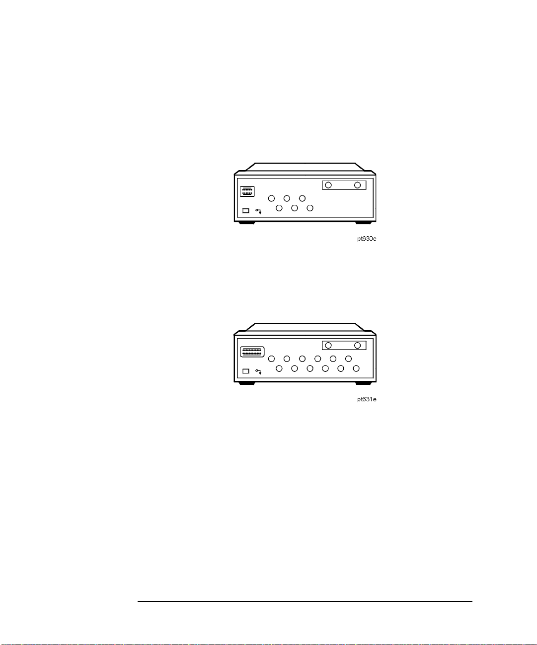
Figure 1-1 87075C Multiport Test Set — Two Versions
87075C Option 006 — Six Port Test Set
87075C Option 012 — Twelve Port Test Set
8 Chapter 1
Page 17

Introduction and Installation
Installation
Step 1. Check the Shipment
After you have unpacked your test set, keep the packaging materials to use if your
instrument should need to be returned for maintenance or repair.
NOTE The packaging material is designed to protect the test set from damage that can
happen during shipping. Returning the test set in anything other than the original
packaging may result in non-warranted damage.
Check the items received against Table 1-1 to make sure that you received everything.
Chapter 1 9
Page 18

Introduction and Installation
Installation
Table 1-1 Test Set Accessories Supplied
Item No. Description Quantity Part Number
1 Power Cord 1 See Figure 4-3. 2 Type-N Cable (Analyzer to test set’s
REFLECTION Port)
1
3 Type-N Cable (Analyzer to test set’s
TRANSMISSION Port)
1
4 Type-N Cable (Analyzer to test set’s
REFLECTION Port)
2
5 Type-N Cable (Analyzer to test set’s
TRANSMISSION Port)
2
1(75 Ω) 87075-60026
1(75 Ω) 87075-60028
1(75 Ω) 87075-60027
1(75 Ω) 87075-60029
6 Parallel Port Interface Cable 1 8120-6818 7 87075C User's and Service Guide (for E506x
1
87075-90027
Network Analyzers)
87050E and 87075C User’s and Service Guide
1
87050-90026
(for 871x Network Analyzers) 8 Test Set Calibration Disk 1 N/A 9 Performance T es t Progr ams Disks
1 08714-60049
(DOS and LIF formats) 10 CD-ROM 1 08714-90051
1. Not to be used with a rack-mounted system or if the analyzer has had its bottom feet removed.
See Figure 1-6 to see how these cables are to be connected.
2. You will only receive these cables if you ordered Option 1CM (rack mount kit). Use these cables
if you are rack-mounting your system, or if the bottom feet of the analyzer have been removed.
See Figure 1-6 for information on how to connect these cables.
10 Chapter 1
Page 19
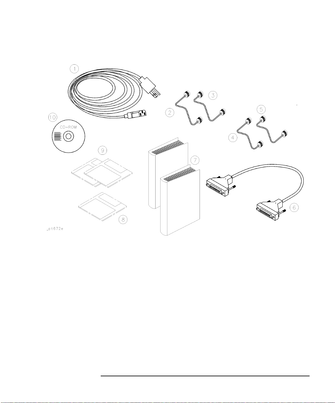
Figure 1-2 Test Set Accessories Supplied
Introduction and Installation
Installation
Step 2. Determine Network Analyzer Compatibility
If you are using a 8712ET/ES or 8714ET/ES analyzer, refer t o “If You are Using an
8712ET/ES or 8714ET/ES Analyzer”.
Chapter 1 11
Page 20

Introduction and Installation
Installation
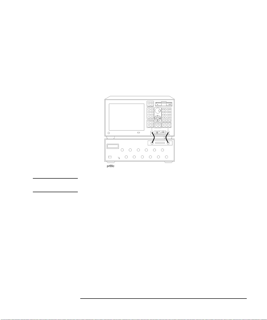
Step 3. Connect the Test Set to the Analyzer
For using your system on a bench, configure and connect the two instruments as shown in Figure 1-3: Connect the Parallel In connector of the test set to the analyzer Parallel connector. Use the parallel cable that was shipped with the multiport test set.
If you will be installing your system in a rack, read “Installing the System in a
Rack,” next in this section, before connecting the test set to the analyzer.
Figure 1-3 System Configuration
Installing the System in a Rack
The rack mount kit for the test set is Option 1CM when ordered with the test set, or
part number 5063-9214 when ordered separately.
12 Chapter 1
Page 21

Introduction and Installation
Installation
NOTE There are special semi-rigid cables that should be used to connect th e analyzer’ s test
ports to the test set’s REFLECTION and TRANSMISSION ports when used in a
rack (or a bench configuration where the analyzer’s bottom feet have been
removed). These cables were shipped with your analyzer if you ordered Option
1CM. If you order the rack mount kit separately, you will need to order these special
cables separately also. See Table 1-1 for part numbers.
To install your system in an 85043D rack, follow the instructions in the rack manual.
CAUTION When installing your system in other racks, improper installation may cause shock
hazards, overheating, dust contamination, and inferior system performance. For
support details and information about installation and warranty, call Agilent
T ech nolog ies. See page 120 for contact information.
CAUTION When installing the system in a cabinet, the convection into and out of the system
must not be restricted. The ambient temperature (outside the cabinet) must be less
than the maximum operating temperature of the system by 4 °C for every 100 watts
dissipated in the cabinet. If the total power dissipated in the cabinet is greater than
800 watts, then forced convection must be used.
Chapter 1 13
Page 22

Introduction and Installation
Installation
Step 4. Satisfy Electrical and Environmental Requirements
NOTE Refer to your network analyzer’s User’s Guide for information on electrical and
environmental requirements for your network analyzer.
1. The line power module on your multiport test set has an autoranging input. It is
designed to be used with an ac power source with a nominal voltage of either
115 V or 230 V.
2. Ensure the available ac power source meets the following requirements:
Nominal Range
Frequency: 50/60 Hz 47–63 Hz Line Voltage: 100/115 V or 230/240 V 90–264 V Power 45 W max
CAUTION This product has an autoranging line-voltage input. Be sure the supply voltage is
within the specified range.
If the ac line voltage does not fall within these ranges, an autotransformer that
provides third-wire continuity to earth ground should be used.
3. Ensure the operating environment meets the following requirements for safety:
• indoor use
• altitude up to 15,000 feet (4,572 meters)
•temperature 0 °C to 55 °C
• maximum relative humidity 80% for temperatures up to 31 °C decreasing
linearly to 50% relative humidity at 40 °C
• use only in INSTALLATION CATEGORY II, and POLLUTION DEGREE
2, per IEC 1010 and 664 respectively
4. Verify that the power cable is not damaged, and that the power source outlet
provides a protective earth ground contact. Note that the following illustration
depicts only one type of power source outlet. Refer to Figure 4-3 to see the
different types of power cord plugs that can be used with your test set.
14 Chapter 1
Page 23

Figure 1-4 Protective Earth Ground
Introduction and Installation
Installation
WARNING This is a Safety Class I product (provided with a protective earthing ground
incorporated in the power cord). The mains plug shall only be inserted in a
socket outlet provided with a protective earth contact. Any interruption of the
protective conductor, inside or outside the instrument, is likely to make the
instrument dangerous. Intentional interruption is prohibited.
Chapter 1 15
Page 24
Introduction and Installation
Installation
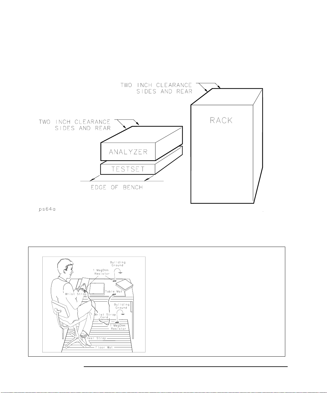
5. Ensure there are at least two inches of clearance around the sides and back of the
test set or the system cabinet.
Figure 1-5 Ventilation Clearance Requirements
6. Set up a static-safe workstation. Electrostatic discharge (ESD) can damage or destroy components.
• table mat with earth ground wire: part number 9300-0797
• wrist-strap cord with 1 Meg Ohm
resistor:
part number 9300-0980
• wrist-strap:
part number 9300-1367
• heel straps:
part number 9300-1308
• floor mat
16 Chapter 1
Page 25
Step 5. Activate the Test Set
1. Connect the semi-rigid cables that were shipped with your test set as shown in
Figure 1-6. Check Table 1-1 to be sure that you are using the correct cables with
your system configuration (the cables you use will be different depending on
whether you are using a bench system configuration—as shown in Figure
1-6—or a rack configuration).
Figure 1-6 Connect the Front Panel RF Cables
Introduction and Installation
Installation
NOTE Steps 2 and 3 must be performed before you can use your network analyzer to
control the multiport test set.
2. Turn on the test set .
3. Turn on the analyzer and Press [System] - activate the test set control.
Chapter 1 17
87075 Setup - 87075 Control to
Page 26

Introduction and Installation
Installation
Step 6. Connect Peripheral Devices
After you’ve ensured that your syst em is work ing pro perl y, connect any peripherals
that you intend to use with your system.
NOTE See your analyzer’s User’s Guide for information on peripheral connections.
18 Chapter 1
Page 27

Introduction and Installation
Preventive Maintenance
Preventive Maintenance
Preventive maintenance consists of checking the front panel connectors. This should
be done at least every six months — more often if the test set is used daily on a
production line or in a harsh environment.
Visually inspect the front panel connectors. The most important connectors are
those to which the DUT is connected. All connectors should be clean and the center
pins centered. The fingers of female connectors should be unbroken and uniform in
appearance. If you are unsure whether the connectors are good, gauge the
connectors to confirm that their dimensions are correct.
CAUTION Never connect 50 ohm cables to the front panel 75 ohm connectors of the analyzer
or test set. Otherwise, irreparable connector damage will occur.
Cleaning the Test Set
Use a dry cloth or one slightly dampened with water to clean the external case parts .
Do not attempt to clean internally.
WARNING To prevent electrical shock, disconnect the test set from power mains before
cleaning.
Chapter 1 19
Page 28

Introduction and Installation
Preventive Maintenance
20 Chapter 1
Page 29

2 Making Measurements
This chapter describes the procedure of measurement using the 87075C multi-port test set.
21
Page 30

Making Measurements
Measurement Procedures
Measurement Procedures
Measurement is performed in 4 major steps below.
• Setting the port connections of the multi-port test set
• Setting the measurement conditions
• Calibrating the test set
• Performing measurement
Multiport test system needs to be properly installed before making measurem ents.
For the installation procedure see “Installation” on page 1-7.
Figure 2-1 Mult iport Test System
Setting port connections of the multi-port test set
The procedure to set the test set port connections is described below. Note that the
port connections are set separately for each measurement channel.
Step 1. Press [Channel Next] or [Channel Prev] to select the channel for which you want
to execute multi-port measurement.
22 Chapter 2
Page 31

Step 2. Press [System].
Making Measurements
Measurement Procedures
Step 3. Press
Step 4. Press
Step 5. Press
87075 Setup.
87075 Control to make the status on.
Reflection.
Step 6. Select the port to be connected to the reflection port.
Step 7. Press
Transmission.
Step 8. Select the port to be connected to the transmission port.
Step 9. Repeat Step 1 through Step 8 for all the channels to use.
Setting the measurement conditions
The procedure to set the measurement conditions is described below. Keys or
softkeys typically used in each step are shown. For more information, see the
E5061A/E5062A User’s Guide.
Step 1. Setting measurement parameter for each trace
Set measurement parameter to be measured for each trace.
[Meas] -Corresponding softkey
Step 2. Setting the stimulus for each trace
Set the stimulus (sweep type, sweep range, power range, etc.) for each trace.
[Sweep Setup] - Corresponding softkey
[Start], [Stop], [Center], [Span] (each key for specifying the sweep range)
Step 3. Setting the data format for each trace
Set the display data format (log amplitude, polar coordinates, etc.).
[Format] - Corresponding softkey
Step 4. Setting the scale for each trace
Set the scale for each trace so that you can observe comfortably.
[Scale] -
Divisions
[Scale] - Scale/Div
Chapter 2 23
Page 32

Making Measurements
Measurement Procedures
[Scale] - Reference Position [Scale] - Reference Value
Step 5. Other settin gs
Set the graph title, trace color, and so on as necessary.
[Display] -
Edit Title Label
[System] - Misc Setup - Color Setup - Corresponding softkey
24 Chapter 2
Page 33

Making Measurements
Measurement Procedures
Calibrating the test set
The procedure to calibrate the test set is described below. Note that the calibration
procedure described here is a typical one using a mechanical calibration kit. For
more detailed information, including procedures using ECal, see Chapter 3.
Step 1. Selecting a mechanical calibration kit
Select a mechanical calibration kit you want to use for calibration. You can select a
mechanical calibration kit using one of the following 2 methods.
[Cal] - Cal Kit - Subsequent corresponding softkeys
[Cal] - Test Set Cal - Calibration - Cal Kit - Subsequent corresponding softkeys
Step 2. Selecting Cal Type
Select a calibration method from full 2-port calibration or enhanced response
calibration. If the E5061A/62A is of the T/R test set type you cannot select the full
2-port calibration.
[Cal] - Test Set Cal - Calibration - Cal Type
Step 3. Selecting an adjacent port pair and executing the measurement of the calibration
standards
Select an adjacent port pair for which you want to perform test set calibration.
Adjacent port pairs are: [1, 2], [3, 4], [5, 6], [7, 8], [9, 10], and [11, 12]. For the
87075C multi-port test set, calibration is performed for each port pair. For this
reason, when you want to use, for example, ports 1 and 5, you need to calibrate 4
ports (ports 1 and 2, and ports 5 and 6).
[Cal] - Test Set Cal - Calibration - Port x-y - Port x Open
[Cal]
- Test Set Cal - Calibration - Port x-y - Port x Short
- Test Set Cal - Calibration - Port x-y - Port x Load
[Cal]
- Test Set Cal - Calibration - Port x-y - Port y Open
[Cal]
[Cal]
- Test Set Cal - Calibration - Port x-y - Port y Short
- Test Set Cal - Calibration - Port x-y - Port y Load
[Cal]
- Test Set Cal - Calibration - Port x-y - Port x-y Thru
[Cal]
Chapter 2 25
Page 34

Making Measurements
Measurement Procedures
Step 4. Executing calibration
After the measurement of the calibration standards for necessary ports is finished,
calculate and save the calibration coefficients.
[Cal] - Test Set Cal - Calibration - Done
NOTE The calibration data of the 87075C multi-port test set has higher priority over the
analyzer’s normal calibration data. Therefore, if Test Set Cal is turned on with
normal calibration data existed, the multi-port test set calibration data is used, and
the normal calibration data is ignored.
26 Chapter 2
Page 35

Performing Measurements
The procedure to execute measurement is described below. This section describes
how to trigger actual measurement. For more information, see the E5061A/62A
User’s Guide.
Step 1. Setting the trigg e r sour ce
Select a trigger source. Because the trigger source is common to all the channels,
you need not to set it channel by channel.
Making Measurements
Measurement Procedures
[Trigger] -
Step 2. Setting the trigger mode
Select a trigger mode. You must set it separately for each channel.
[Trigger] - Corresponding softkey
Step 3. Generating a trigger
Generate a trigger from the trigger source specified in setting the trigger source.
NOTE If the internal trigger is specified, triggers are generated continuously immediately
after the setting.
Step 4. Adjusting the settings
Adjust each setting made in “Setting the measurement conditions” according to your measurement needs.
Trigger Source - Corresponding softkey
Chapter 2 27
Page 36

Making Measurements
Measurement Procedures
28 Chapter 2
Page 37

3 Test Set Cal and SelfCal
29
Page 38

Test Set Cal and SelfCal
Introduction
Introduction
This chapter presents information on the following topics:
• Test Set Cal: An Overview
• Test Set Cal and SelfCal: Theory of Operation
Measurement calibration is a process that improves measur ement accuracy by us ing
error correction arrays to remove systematic measurement errors. By implementing
the T est Set Cal and SelfCal features on your multiport system, you can increase the
accuracy of your measurements and increase the throughput of your multiport
measurements by eliminating frequent and lengthy calibration procedures.
Cal Type What is it? When to do it?
Test Set Cal
SelfCal An internally automated
A full calibration of the
multiport test system.
Requires connections of
external calibration
standards.
calibration techniq ue.
Uses solid-state switches
to measure calibration
standards located inside
the test set.
When you first set
up your test
system. Thereafter,
about once a month
if within the
specified
temperature range.
Set SelfCal to execute automatically as often as needed (typically once an hour).
Test Set Cal
A Test Set Cal is a calibration that should be performed when you first set up your
test system and thereafter on a regular, but relatively infrequent basis. The time
interval between Test Set Cals is dependent mainly on temperature. If the operating
temperature of the analyzer and test set is within the specified range, the
recommended time interval is about once a month. A Test Set Cal requires you to
connect calibration standards to all of the ports to be used.
See “Test Set Cal: An Overview” to learn how to perform a Test Set Cal.
30 Chapter 3
Page 39

Test Set Cal and SelfCal
Introduction
SelfCal
A SelfCal is an automated internal system calibration that should be performed on a
regular, frequent basis. If the operating temperature of the analyzer and test set is
within the specified range (refer to Chapter 8), the recommended time interval is
about once an hour. A SelfCal does not require removal of the DUT or external
connections of calibration standards. The SelfCal uses the results of the most recent
Test Set Cal along with measurements of internal, electronically switched open,
short, load, and through transfer standards to remove the drift of the network
analyzer and multiport test set due to environmental variations.
See “Test Set Cal and SelfCal: Theory of Operation” for detailed information on
how the Test Set Cal and SelfCal work together.
NOTE Agilent recommends that you use the Test Set Cal and SelfCal features whenever
you are using your multiport system. If you prefer, you can select from traditional
analyzer calibrations, although in doing so the Test Set Cal and SelfCal features will
not be available. Refer to your analyzer’s User’s Guide for information on these
traditional calibrations.
Chapter 3 31
Page 40

Test Set Cal and SelfCal
T est Set Cal: An Overview
Test Set Cal: An Overview
To perform a Test Set Cal the following steps are required and are explained in
detail in this section:
1. Set up measurement parameters, such as frequency range, power level, number
of measurements points, etc.
2. Determine the best position for the calibration reference plane.
3. Determine the type of calibration kit you will need to match the connectors at
your calibration reference plane.
4. Determine the number of test set ports to be used.
5. Perform the Test Set Cal.
The following optional steps are also explained in detail in this section:
6. Save the Test Set Cal.
7. Recall the Test Set Cal.
8. Copy the Test Set Cal.
9. Execute the SelfCal.
Setting Up the Measurement Parameters
You will need to determine th e measurem ent pa r a met e rs for your Test Set Cal by
determining all the measurements you will be making on a particular device and
setting your parameters accordingly. The analyzer will be able to accurately
interpolate between error-correction data po ints when most param eters are changed.
However, some special considerations are discussed below.
Frequency Range
You should set your freq uenc y range to the narrowest span possible that will cover
all of the measurements you will be making. The analyzer uses a fixed number of
frequency points during a calibration and interpolates as the frequency span is
narrowed. Setting the analyzer to the narrowest span possible for your
measurements will ensure the most accurate calibration. For example, if you will be
measuring a device that requires three different measurements, set your start
frequency to the lowest frequency used among the measurements and your stop
frequency to the highest frequency used among the measurements. See Figure 3-1.
32 Chapter 3
Page 41

The analyzer will interpolate between calibrated measurement points when the
frequency span is narrowed. However, you should be aware that best measurement
accuracy is compromised with this interpolation.
Figure 3-1 Frequency Range Example
Test Set Cal and SelfCal
T est Set Cal: An Overview
NOTE It is recommended that you set yo ur s t op f requ e ncy to 1 300 MH z. The per for mance
of the test set is not specified above 1300 MHz.
Using this method of calibration will yield accurate measurements with optimum
throughput. If your accuracy req uiremen ts are mo re imp ortant than you r th roug hp ut
requirements, you may want to perform a separate Test Set Cal for each
measurement setup, which eliminates the need for the analyzer to use interpolation.
Chapter 3 33
Page 42

Test Set Cal and SelfCal
T est Set Cal: An Overview
Other Parameters to Consider
The following parameters, if changed after calibrating, will not invalidate the
calibration, but will cause the “C?” notation to appear at the status bar of the
display:
• Sweep time
• Number of points
•Power level
• IF bandwidth
The “C?” notation indicates that a measurement parameter has changed after a
calibration was performed. For best accuracy, avoid measurements which cause the
“C?” notation to appear.
There is a trade-off be tween selecting the par ameters for best m easurement accuracy
and the resulting time required for the SelfCal routine. Generally, as your
parameters are modified for the greatest accuracy, the time required for a SelfCal
increases. For example, selecting a large number of points and a narrow system
bandwidth will improve measurement accuracy but will increase the time needed for
SelfCal. Therefore, when choosing parameters, you will have to weigh the
importance of measurement accuracy versus throughput.
Determining the Best Position for the Calibration Reference Plane
Most often you will not be connecting your DUT directly to the test set front panel.
More likely , you will be connecting you r DUT to a test fixture or t est cables t hat are
connected to the test set. See Figure 3-2 for an example. The calibration reference
plane is where you connect your calibration standards, and the measurement
reference plane is where you connect your DUT. Best measurement results occur
when these reference planes are aligned so that you calibrate out the effects of the
test fixture and its associated cables and hardware. Figure 3-2 illustrates how to
align the reference planes by connecting y our calibration stand ards at the same point
that you connect your DUT.
34 Chapter 3
Page 43

Figure 3-2 The Calibration Reference Plane
Test Set Cal and SelfCal
T est Set Cal: An Overview
Chapter 3 35
Page 44

Test Set Cal and SelfCal
T est Set Cal: An Overview
CAUTION Although the T est Set Cal can calibrate out the ef fects of you r external hardware, the
drift-removing features of the SelfCal cannot remove drift associated with any
external fixtures or cabling. See Figure 3-4.
Be sure that all external fixtures and cables are extremely stable. Agilent
recommends the use of semi-rigid cabling external to your multiport test set. Design
fixturing such that movement of all cables and connectors is minimized.
Determining the Type of Calibration Kit to Use
For the most accurate calibrations and measurements, you should select a calibration
kit to match each connector of your DUT. This will en sure that no adapters are
needed after a calibration has been performed. Procedures to select a calibration kit
is given below. For more information on calibration kits, refer to the
E5061A/E5062A User’s Guide.
Step 1. Press [Channel Next] or [Channel Prev] to select the channel for which you want
to select the calibration kit.
Step 2. Press [Cal].
Step 3. Press
Step 4. Select the calibration kit you use.
NOTE Alternatively , you can also u se [Cal] - Test Set Cal - Calibration - Cal Kit to select a
Step 1. Press [Channel Next] or [Channel Prev] to select the channel for which you want
Step 2. Press [Cal].
Step 3. Press
NOTE The calibration kit definitions for Port 1 are used for the test set ports with an odd
Cal Kit.
mechanical calibration kit. Follow these steps.
to select the calibration kit.
Test Set Cal - Calibration - Cal Kit and select a calibration kit you want to use
from the softkey menu.
number, while the definitions for Port 2 are used for the ports with an even number.
36 Chapter 3
Page 45

Test Set Cal and SelfCal
T est Set Cal: An Overview
Determine the Test Set Ports to Be Used
T o save time, calibrate the lowest number of ports necessary for your test setup. For
example, if your test setup requires the use of only 6 of the available twelve ports,
calibrate for 6 ports; there is no need to spend the time to calibrate all twelve ports.
The selection of the number of ports is necessary, in part, in order to perform the
minimum-through portion of the Test Set Cal. This portion occurs during the
calibration when measuring through standards for a transmis sion measurement (S
or S
) or measurements using 2-port calibration. Suppose that you have a 6-port
12
DUT and that you have selected the ports 1 to 6 to calibrate on your test set. A
traditional network analyzer calibration would require (in addition to connecting
opens, shorts, and loads to all connectors) that you connect a through standard
between every possible pairing of the 6 test set ports in order to measure all possible
transmission paths. This would mean 15 dif ferent connect ions of thro ugh standar ds,
each needing its own separate calibration file. The Test Set Cal simplifies this
process by only requiring a through-standard connection between 3 adjacent port
pairs of the 6 test set ports:
• Port 1 to Port 2
21
*
• Port 3 to Port 4
• Port 5 to Port 6
The analyzer calculates the remainder of the test set port combinations and saves the
data as only one calibration file. The test set calibration can be done in any
combination of the adjacent port pairs, [1, 2] and [5, 6] for example. This results in
significant calibration-time savings, which improves your measurement throughput.
Performing the Test Set Cal with a Mechanical Calibration Kit
This section describes how to perform the Test Set Cal with a mechanical calibration kit.
Step 1. Press [Channel Next] or [Channel Prev] to select the channel for which you want
to execute multi-port test set calibration.
Step 2. Press [Cal].
* Adjacent ports are those which share an internal through calibration stan-
dard. Adjacent ports are: [1, 2], [3, 4], [5, 6], [7, 8], [9, 10], [11, 12].
Chapter 3 37
Page 46

Test Set Cal and SelfCal
T est Set Cal: An Overview
Step 3. Press Test Set Cal.
Step 4. Press
Calibration.
NOTE If Calibration is disabled, the status of the multi-port test set of this channel may be
off. See "Procedure of setting ports for the multi-port test set" in the previous
chapter.
Step 5. Press
Port x-y (a port pair for which you want to execute calibration).
NOTE The multi-port test set calibration is perfo rmed for each port p air. If you want to use,
for example, ports 1 and 3 for measurement, calibration must be performed for 1-2
and 3-4.
Step 6. Connect the open standard to the Port x side and press
calibration data.
Step 7. Connect the short standard to the Port x side and press
calibration data.
Step 8. Connect the load standard to the Port x side and press
calibration data.
Step 9. Connect the open standard to the Port y side and press
calibration data.
38 Chapter 3
Port x Open to measure
Port x Short to measure
Port x Load to measure
Port y Open to measure
Page 47

Test Set Cal and SelfCal
T est Set Cal: An Overview
Step 10. Connect the short standard to the Port y side and press Port y Short to measure
calibration data.
Step 11. Connect the load standard to the Port y side and press
Port y Load to measure
calibration data.
Step 12. Connect the thru standard between ports x and y side and press
measure calibration data.
Portx- y Thru to
Step 13. Press
Return to return to the port selection menu.
Step 14. Repeat Step 5 through Step 13 for necessary port pairs.
NOTE When you calibrate the same port pair in multiple channels, you can reduce the
number of standard connections by measuring a standard while changing
measurement channels. You don’t need to complete the step 5 through 13 before
you perform calibration in other channel, thus you can measure standards for Test
Set Cal in parallel in multiple channels.
Step 15. Press
Done to finish the calibration of the multi-port test set. The calibration
coefficients are calculated and saved by this operation.
Chapter 3 39
Page 48

Test Set Cal and SelfCal
T est Set Cal: An Overview
Calibrating: Insertable Port Pairs versus Noninsertable Port Pairs
During the through portion of the calibration, if an adjacent port pair (for example,
1-to-2, 3-to-4, 5-to-6, etc.) can be connected directly without using a cable or an
adapter, the port pair is insertable. If an adjacent port pair can only be connected by
using a through cable or an adapter, the port pair is noninsertable. If the port pair is
noninsertable, the through cable or adapter is not used when the DUT is measured,
so its electrical delay must be subtracted out. This is done by modifying the
definition of the through-standard in the calibration kit for each port.
Most test fixtures have fixed-location connectors, so their port pairs can only be
connected by using a through cable. During the calibration you will be prompted to
connect a through cable between specific port pairs. If you can connect your cables
to the test set so that the cables’ adjacent port pairs are male-to-female, all of your
port pairs will be insertable. Configuring your test setup this way saves calibration
time and improves your measurement throughput.
Performing the Test Set Cal with an ECal Module
This section describes how to perform the Test Set Cal with an ECal module.
Step 1. Press [Channel Next] or [Channel Prev] to select the channel for which you want
to execute multi-port test set calibration.
Step 2. Press [Cal].
Step 3. Press
Step 4. Press
NOTE If Calibration is disabled, the status of the multi-port test set of this channel may be
Step 5. Press
NOTE The multi-port test set calibration is perfo rmed for each port p air. If you want to use,
Te st Set Cal.
Calibration.
off. See "Procedure of setting ports for the multi-port test set" in the previous
section.
Port x-y (a port pair for which you want to execute calibration).
for example, ports 1 and 3 for measurement, calibratio n must be perfo rmed for p orts
1-2 and 3-4.
40 Chapter 3
Page 49

Test Set Cal and SelfCal
T est Set Cal: An Overview
Step 6. Connect the ECal module between ports x and y and press ECal to measure
calibration data and calculate the calibration coefficients.
Step 7. Repeat Step 5 and Step 6 for necessary port pairs.
Chapter 3 41
Page 50

Test Set Cal and SelfCal
T est Set Cal: An Overview
NOTE A 2-port type ECal module is assumed in the above procedure. For a 4-port ECal
module, in case of S-parameter test set, you can connect any two of the 4 ports when
connecting the ECal module in St ep 6. In case of transmission /reflection test set, on e
of the connections listed in the table must be used.
4-Port ECal connection to T/R test set
Reflection Transmission
Port A Port B Port B Port C Port C Port D Port D Port A
Saving the Test Set Cal
It is a good idea to manually save the results of your Test Set Cal. You can save the
test set cal data as a part of the instrument state. Following is a basic procedure to
save the instrument state into the pre-defined register. See your analyzer’s User’s
Guide for more detailed information on saving, and recalling files.
Step 1. Press [Channel Next] or [Channel Prev] to select the channel for which you want
to save calibration data.
Step 2. Press [Save/Recall].
Step 3. Press
Step 4. Press
Save Type, then either State & Cal or All so that the calibration data is included in
the state data.
Save State, then the softkey corresponding to the register in which you want to
save the instrument state.
Recalling the Test Set Cal
You can recall the test set cal data as a part of the instrument state. Following is a
basic procedure to recall the instrument state from the pre-defined register. See your
analyzer’s User’s Guide for more detailed information on s avi ng, and recal l ing files.
Step 1. Press [Channel Next] or [Channel Pr ev] to select the ch annel for which y ou want
to recall calibration data.
42 Chapter 3
Page 51

Step 2. Press [Save/Recall].
Test Set Cal and SelfCal
T est Set Cal: An Overview
Step 3. Press
Recall State, then the softkey corresp onding to the r egister from which you w ant
to recall the instrument state.
Copying the Test Set Cal.
The E5061A/62A lets you temporarily save Test Set calibration data only for each
channel and copy it to another channel. When the same calibration data is used in
multiple channels, you can reduce calibration time by using this method instead of
doing the same calibration multiple times. The procedure is as follows:
Step 1. Press [Channel Next] or [Channel Prev] to select the channel for which you want
to save calibration data temporarily.
Step 2. Press [Save/Recall].
Step 3. Press
Step 4. Press one of
NOTE An area with an asterisk (*) to the right of Cal Only x contains saved data alread y. If
Step 5. Press [Channel Next] or [Channel Prev] to select a channel to which you want to
Save Channel.
Cal Only A through Cal Only D.
you press the key, the previous calibration data is deleted and new calibration data is
written over it. In this case, the previous calibration data cannot be restored.
copy calibration data.
Step 6. Press [Save/Recall].
Step 7. Press
Step 8. Press
NOTE Only keys for which saved data exists are active.
Recall Channel.
Cal Only x in which you have saved calibration data to read it out.
Executing Self Cal
The SelfCal timer feature allows you to set up your multiport system to
automatically perform a SelfCal at a user-defined interval. The default interval is 60
minutes. Your environmental conditions and accuracy requirements may dictate
either a shorter interval or allow a longer interval.
Chapter 3 43
Page 52

Test Set Cal and SelfCal
T est Set Cal: An Overview
NOTE Self Cal is set for each measurement channel and executed for a port pair selected
for the channel.
NOTE SelfCals are not automatically initiated on currently unused ports. A port is never
automatically calibrated unless it is selected— even if the time interval has been
exceeded.
NOTE SelfCals are initiated only when a trigger source is internal and a trigger mode is
continuous.
Step 1. Press [Cal].
Step 2. Press
Step 3. Press
Te st Set Cal.
Timer and enter the interval for executing Self Cal in minutes in the entry area
in the upper part of the screen.
Step 4. Press
Self Cal to make the auto Self Cal status on.
NOTE You can execute a Self Cal on the currently selected channel by press ing [Cal] - Test
Set Cal - Self CalOnce.
44 Chapter 3
Page 53

Test Set Cal and SelfCal
Test Set Cal and SelfCal: Theory of Operation
Test Set Cal and SelfCal: Theory of Operation
Adding a multiport test set to the analyzer degrades raw performance of the test
system as well as introduces drift. Test Set Cal provides the vector error correction
that allows the system to achieve good performance. A Test Set Cal is a calibration
that is performed on a regular, but infrequent basis. The results of the Test Set Cal
are used by the SelfCal feature to remove the drift associated with the hardware of
the test set and analyzer to return the multiport system to an accurately calibrated
state.
There are two steps to the Test Set Cal:
• The first step requires you to connect calibration standards (from a calibration
kit) and your own through-cables to the calibration reference plane. The
analyzer measures the known reference standards and uses those measurements
to compute error correction coefficients.
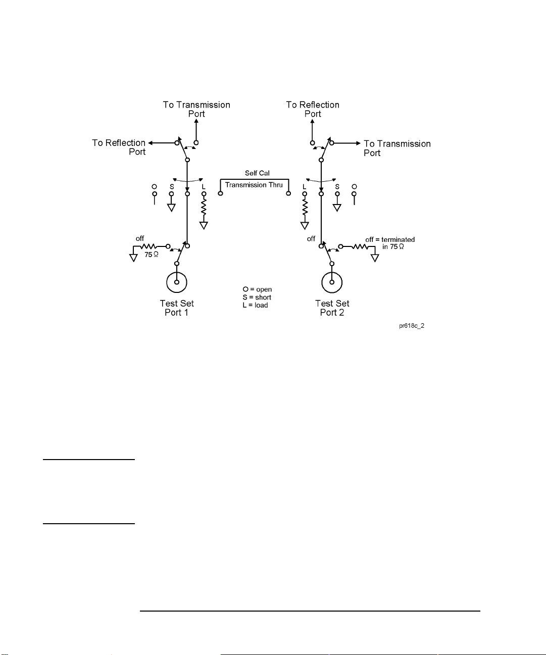
• The second step occurs once you are done measuring the calibration standards
and store the Test Set Cal data. The multiport test set contains electronically
switched open, short, load, and through standards behind each port. (See Figure
3-3. This illustration depicts a two-port t e st set. The same internal sta ndards are
also included behind every port of your test set.) These standards are very stable,
yet their calibration definitions are not known like the mechanical standards.
During this second step, the analyzer makes a measurement of each internal
standard and then, using the error coefficients that were computed from the
measurements of the external standards, derives a very accurate calibration
definition for each internal standard. Once this has been done, the internal
standards act as “transfer standards” for future automatic calibrations called
SelfCals.
Chapter 3 45
Page 54
Test Set Cal and SelfCal
Test Set Cal and SelfCal: Theory of Operation
Figure 3-3 Internal Transfer Standards
A SelfCal is an automatic measurement of the test set internal standards that allows
the system to remove system drift that occurs du e to en viron mental ch anges s uch as
temperature. SelfCal allows the multiport system to recalibrate itself without having
to disconnect the DUT or connect any additional external standards or cables to the
system.
A SelfCal can be initiated manually. It is also possible to automatically perform a
SelfCal at regular, frequent time intervals. If the operating temperature of the
analyzer and test set is within the specified range (refer to Chapter 8), the
recommended time interval is about once an hour.
CAUTION Performing a Test Set Cal will effectively calibrate out the initial effects of any
external cabling and/or test fixtures. However, it must be noted that although the
SelfCal can remove drift internal to the measurement system, it cannot remove any
drift associated with cables, test fixtures and connections beyond the internal
transfer standards.
As shown in Figure 3-4, the Test Set Cal initially removes the effects of drift associated with hardware in the area designated by arrow “A.” SelfCal can only remove the effects of drift from the area designated by arrow “B.”
46 Chapter 3
Page 55

Test Set Cal and SelfCal: Theory of Operation
Drift can be minimized by controlling the environmental temperature and humidity,
and by using high quality connectors, semi-rigid cables, and fixturing that reduces
cable movement to a minimum.
Figure 3-4 Drift Removal: Test Set Cal and SelfCal
Test Set Cal and SelfCal
Chapter 3 47
Page 56

Test Set Cal and SelfCal
Test Set Cal and SelfCal: Theory of Operation
48 Chapter 3
Page 57

4 Front/Rear Panel
49
Page 58

Front/Rear Panel
This chapter contains information on the ports and switches found on the front and
rear panels of the test set.
50 Chapter 4
Page 59

Front Panel
Figure 4-1 Front Panel Features
Front/Rear Panel
Front Panel
Item Description
1 Line Power Switch 2 Port Connection Status LEDs 3 Reflection and Transmission Connectors 4Test Ports 5 Chassis Ground Connector
Line Power Switch
The test set line POWER switch is located at the bottom left corner of the front panel. See Figure 4-1. The line POWER switch turns the power to the test set to either on or off.
Chapter 4 51
Page 60

Front/Rear Panel
Front Panel
The front panel LINE switch disconnects the mains circuits from the mains supply
after the EMC filters and before others parts of the instrument.
Test Ports
The front panel test ports are 75 ohm female connectors that are used to connect to
the device under test.
CAUTION Never connect 50 ohm cables to the front panel 75 ohm connectors of the analyzer
or test set. Otherwise, irreparable connector damage will occur.
52 Chapter 4
Page 61

Front/Rear Panel
Front Panel
The REFLECTION Connector
The REFLECTION connector is a female 75 ohm type-N connector that connects
directly to the PORT 1 of the network analyzer using a semi-rigid cable that was
shipped with your test set.
CAUTION Check your analyzer's documentation for damag e limits to th e analyzer po rts. Make
sure that your test setup will not cause those limits to be exceeded.
The TRANSMISSION Connector
The TRANSMISSION connector is a female 75 ohm type-N connector that
connects directly to the PORT 2 of the network analyzer using a semi-rigid cable
that was shipped with your test set.
CAUTION Check your analyzer's documentation for damag e limits to th e analyzer po rts. Make
sure that your test setup will not cause those limits to be exceeded.
The Chassis Ground Connector
The chassis ground connector provides a convenient front panel ground connection
for a standard banana plug.
The PORT CONNECTION Status LEDs
The PORT CONNECTION status LEDs provide visual feedback of which test set
port(s) are connected to the REFLECTION and TRANSMISSION connectors of the
test set. When neither LED is lit for a particular test set port, the test set port is
terminated with the internal load.
Chapter 4 53
Page 62

Front/Rear Panel
Rear Panel
Rear Panel
Figure 4-2 Rear Panel Features
Item Description
1 Parallel In Connector
2 Parallel Out Connector
3Line Module
The PARALLEL IN Connector
This female DB-25 connector input is always connected to the network analyzer.
The analyzer provides control of the test set through this cable as well as passing
through any printer control signals to the test set’s PARALLEL OUT connector.
The PARALLEL OUT Connector
This rear panel connector cannot be used when the test set is used with the
E5061A/E5062A. Use the analyzer’s USB ports when using a printer.
54 Chapter 4
Page 63

Front/Rear Panel
Rear Panel
Line Module
The line module contains the power cable receptacle. See “S tep 4 . Satisfy Electrical
and Environmental Requirements” for power supply requirements.
Power Cables The line power cable is supplied in one of several configurations, depending on the
destination of the original shipment.
Each instrument is equipped with a three-wire power cable. When connected to an
appropriate ac power receptacle, this cable grounds the instrum ent chassis . The type
of power cable shipped with each instrument depends on the country of destination.
See Figure 4-3 for the part numbers of these power cables. Cables are available in
different lengths. Check with your nearest Agilent service center for descriptions
and part numbers of cables other than those described in Figure 4-3.
WARNING This is a Safety Class I product (provided with a protective earthing ground
incorporated in the power cord). The mains plug shall only be inserted in a
socket outlet provided with a protective earth contact. Any interruption of the
protective conductor, inside or outside the instrument, is likely to make the
instrument dangerous. Intentional interruption is prohibited.
Chapter 4 55
Page 64

Front/Rear Panel
Rear Panel
Figure 4-3 Power Cable and Line (Mains) Plug Part Numbers
56 Chapter 4
Page 65

5Key Reference
57
Page 66

Key Reference
This chapter contains an alphabetical reference of the networ k analyzer keys that are
used exclusively for the multiport test set. It also contains entries for some of the
network analyzer keys that are likely to be used while making measurements with
your multiport test set. For a complet e referen ce of net wor k anal yzer keys , see yo ur
analyzer’s User’s Guide.
58 Chapter 5
Page 67

Cal Menu
-G[UVTQMG
-G[UVTQMG (WPEVKQP
-G[UVTQMG-G[UVTQMG
[Cal] Displays the softkeys related to setting and executing calibration.
(WPEVKQP 5%2+EQOOCPF
(WPEVKQP(WPEVKQP
Key Reference
Cal Menu
5%2+EQOOCPF
5%2+EQOOCPF5%2+EQOOCPF
Correction Toggles on/off the error correction.
:SENS{1-4}:CORR:STAT
Test Set Cal Displays the softkeys to execute multi-port test set calibration.
Te st Set Cal Enables/disables the calibration data for the multi-port
:SENS{1-4}:CORR:MULT
test set.
Calibration Displays the softkeys to select ports for which you want to perform the calibration of
the multi-port test set or select a calibration method.
Port 1-2
Port1 Open Executes open calibration for port 1 of the multi-port
Port1 Short Executes short calibration for port 1 of the multi-port
Port1 Load Executes load calibration for port 1 of the multi-port test
Port2 Open Executes open calibration for port 2 of the multi-port
Port2 Short Executes short calibration for port 2 of the multi-port
Port2 Load Executes load calibration for port 2 of the multi-port test
Displays the softkeys to calibrate ports 1 and 2 of the multi-port test set.
:SENS{1-4}:CORR:MULT:C
test set.
test set.
set.
test set.
test set.
set.
OLL:OPEN 1
:SENS{1-4}:CORR:MULT:C
OLL:SHOR 1
:SENS{1-4}:CORR:MULT:C
OLL:LOAD 1
:SENS{1-4}:CORR:MULT:C
OLL:OPEN 2
:SENS{1-4}:CORR:MULT:C
OLL:SHOR 2
:SENS{1-4}:CORR:MULT:C
OLL:LOAD 2
Port1-2 Thru Executes thru calibration for ports 1 and 2 of the
multi-port test set.
Port1-2 Isol
(Optional)
Executes isolation calibration for ports 1 and 2 of the
multi-port test set.
Chapter 5 59
:SENS{1-4}:CORR:MULT:C
OLL:THRU 2,1
:SENS{1-4}:CORR:MULT:C
OLL:ISOL 2,1
Page 68

Key Reference
Cal Menu
-G[UVTQMG
-G[UVTQMG (WPEVKQP
-G[UVTQMG-G[UVTQMG
(WPEVKQP 5%2+EQOOCPF
(WPEVKQP(WPEVKQP
5%2+EQOOCPF
5%2+EQOOCPF5%2+EQOOCPF
[Cal]
(Continued)
Test Set Cal
Calibration
Port 1-2
ECal Executes 2-port ECal for ports 1 and 2 of the mu lti- po rt
test set.
:SENS{1-4}:CORR:MULT:C
OLL:ECAL 2,1
Return Returns to the softkey display in one level upper.
Port 3-4 Displays the softkeys to calibrate ports 3 and 4 of the multi-port test set. The lower
level softkeys displayed are the same as those for Port 1-2
.
:
Port 11-12 Displays the softkeys to calibrate ports 11 and 12 of the multi-port test set. The lower
level softkeys displayed are the same as those for Port 1-2.
Cal Type Selects a calibration method for calibrating each port of
the multi-port test set.
Cal Kit
Displays the softkeys to select a calibration kit to calibrate the multi-port test set. The
:SENS{1-4}:CORR:MULT:C
OLL:METH
softkey labels for the calibration kit differ depending on the registered data.
85033E Selects the 85033E calibration kit.
:SENS{1-4}:CORR:COLL:C
KIT 1
: :
User Selects a calibration kit newly registered.
Cancel Returns to the softkey display in one level upper.
Done Finishes the calibratio n and calculates the calibration
coefficients.
Return Returns to the softkey display in one level upper.
Self Cal Toggles on/off the auto calibration feature using the
internal standard of the multi-port test set.
60 Chapter 5
:
:SENS{1-4}:CORR:COLL:C
KIT 10
:SENS{1-4}:CORR:MULT:C
OLL:SAVE
:SENS{1-4}:CORR:MULT:SE
LF
Page 69

-G[UVTQMG
-G[UVTQMG (WPEVKQP
-G[UVTQMG-G[UVTQMG
(WPEVKQP 5%2+EQOOCPF
(WPEVKQP(WPEVKQP
Key Reference
Cal Menu
5%2+EQOOCPF
5%2+EQOOCPF5%2+EQOOCPF
[Cal]
(Continued)
Test Set Cal
Timer Specifies the execution interval of the auto calibration
feature using the internal standard of the multi-port test
set. You can specify 1 or more in minutes.
Self Cal Once Executes the auto calibration feature using the internal
standard for the specified port of the multi-port test set.
Return Returns to the softkey display in one level uppe r.
Return Returns to the softkey display in one level upper .
:SENS{1-4}:CORR:MULT:SE
LF:TIM
:SENS{1-4}:CORR:MULT:SE
LF:ONCE
Chapter 5 61
Page 70

Key Reference
System Menu
System Menu
-G[UVTQMG
-G[UVTQMG (WPEVKQP
-G[UVTQMG-G[UVTQMG
(WPEVKQP 5%2+EQOOCPF
(WPEVKQP(WPEVKQP
5%2+EQOOCPF
5%2+EQOOCPF5%2+EQOOCPF
[System]
87075 Setup Displays the softkeys related to setting the multi-port test set.
87075 Contr ol Enables/disables the multi-port test set.
Reflection Displays the softkeys to select the port for the reflection side of the multi-port test set.
Port 1 Select s Port 1 as the reflection-side port.
:
Port 12 Selects Port 12 as the reflection-side port.
Cancel Aborts the selection and returns to the softkey display in one level upper.
Transmission Displays the softkeys to select the port for the transmission side of the multi-port test
Port 1 Select s Port 1 as the transmission-side port.
:
Port 12 Selects Port 12 as the transmission-side port.
Cancel Aborts the selection and returns to the softkey display in one level upper.
Displays the softkeys related to co ntrol/management features of the ana lyzer.
:SENS{1-4}:MULT
:SENS{1-4}:MULT:PORT1:S
EL 1
:SENS{1-4}:MULT:PORT1:S
EL 12
set.
:SENS{1-4}:MULT:PORT2:S
EL 1
:SENS{1-4}:MULT:PORT2:S
EL 12
Property T o ggles on/of f the c onnection status (propertie s) display
of the multi-port test set.
:SENS{1-4}:MULT:PROP
..
..
..
62 Chapter 5
Page 71

-G[UVTQMG
-G[UVTQMG (WPEVKQP
-G[UVTQMG-G[UVTQMG
(WPEVKQP 5%2+EQOOCPF
(WPEVKQP(WPEVKQP
Key Reference
System Menu
5%2+EQOOCPF
5%2+EQOOCPF5%2+EQOOCPF
[System]
87075 Setup
Return Returns to the softkey display in one level uppe r.
Return Returns to the softkey display in one level upper .
(Continued)
Chapter 5 63
Page 72

Key Reference
System Menu
64 Chapter 5
Page 73

6 SCPI Command Reference
This chapter describes the SCPI command reference for the Agilent
E5061A/E5062A to con tr ol the Agilent 87075C Multi Port Test Set. It describes the
commands using their abbreviated format in alphabetical order.
65
Page 74

SCPI Command Reference
Syntax
Notational conventions in this command reference
This section describes the rules to read the description of the commands in this chapter.
Syntax
Part with heading "Syntax" describes the syntax to send a comm and from the
external controller to the E5061A/E5062A. A syntax consists of a command part
and a parameter part. The separator between the command part and the parameter
part is a space.
If there are several parameters, the separator between adjacent parameters is a
comma (,). 3 points (…) between commas indicate that parameters in that part are
omitted. For example, <value 1>,…,<value 4> indicates that 4 parameters, <value
1>,<value 2>,<value 3>,<value 4>, are required. String-type parameters, <string>,
<string 1>, and so on, must be enclosed in double quotation marks (").
You can omit the lowercase letters in syntax. For example, ":CALibration:CABLe"
can be shortened as ":CAL:CABL.
The definition of symbols used in the syntax is as follows:
<> Characters enclosed in this pair of symbols are necessary
parameter s when sending the command.
[] Part enclosed in this parenthesis pair can be omitted.
{} Part enclosed in this parenthesis pair indicates that you must
select one of the items in this part. Individual items are
separated by a vertical bar (|).
For example, ":CALC:CORR:EDEL:TIME 0.1,"
":CALCULATE1:SELECTED:CORR:EDEL:TIME 25E-3," and so on are valid for
the syntax given below.
Syntax :CALCulate{[1]|2|3|4|5|6}[:SELected]:CORRection:EDELay:TIME <value>
Description
Part with heading "Description" descri bes how to us e the command or the operat ion when executed.
66 Chapter 6
Page 75

SCPI Command Reference
Query response
Parameters
Part with heading "Parameters" describes necessary parameters when sending the
command. When a parameter is a value type or a string type enclosed with <>, its
description, allowable setup range, preset (factory-set) value, and so on are given;
when a parameter is a selection type enclosed with { }, the description of each
selection item is given.
For a value-type parameter noted with "MAX or MIN is available," you can use
MAX (or MAXIMUM) and MIN (or MINIMUM) as its parameter instead of a
value, which specifies the maximum value and minimum value within the allowable
setup range, respectively.
Query response
Part with heading "Query response" describes the data format read out when query
(reading out data) is available with the command.
Each readout parameter is enclosed with {}. If there are several items within {}
separated by the pipe (|), only one of them is read out.
When several parameters are read out, they are separated with a comma (,). Note
that, 3 points (…) between commas indicate that the data of that part is omitted. For
example, {numeric 1},…,
{numeric 4} indicates that 4 data items, {numeric 1}, {numeric 2}, {numeric 3},
and {numeric 4}, are read out.
<newline><^END> after the parameters is the program message terminator.
Related commands
Part with heading "Related commands" describes the commands related to this command.
Equivalent key
Part with heading "Equivalent key" shows the operational procedure of the front
panel keys that has the same effect as this comm and.
[Key] Indicates that you press the key named Key. [Key] - Item Indicates a series of key operation in which you press the [Key]
key, select (highlight) the item called Item on the displayed
Chapter 6 67
Page 76

SCPI Command Reference
Equivalent key
menu using t he [←↓] key and so on, and then press the [Enter]
key.
68 Chapter 6
Page 77

SCPI Command Reference
:SENS{1-4}:CORR:MULT
Multiport Testset Commands
This section describes the commands of 87075C Multiport Testset.
:SENS{1-4}:CORR:MULT
Syntax :SENSe{[1]|2|3|4}:CORRection:MULTiport[:STATe] {ON|OFF|1|0}
:SENSe{[1]|2|3|4}:CORRection:MULTiport[:STATe]?
Description For channel 1 to channel 4, enables/disables the calibration of the test set.
Parameters
Description
ON or 1 Enables the calibration of the test set. OFF or 0 (preset value) Disables the calibration of the test set.
Query response {1|0}<newline><^END>
Example of use
Related commands
Equivalent key
10 OUTPUT 717;":SENS1:CORR:MULT ON" 20 OUTPUT 717;":SE NS1:CORR:MULT?" 30 ENTER 717;A$
[Cal] - Test Set Cal - Test Set Cal
Chapter 6 69
Page 78

SCPI Command Reference
:SENS{1-4}:CORR:MULT:COLL:ECAL
:SENS{1-4}:CORR:MULT:COLL:ECAL
Syntax :SENSe{[1]|2|3|4}:CORRection:MULTiport:COLLect:ECAL <value 1>,<value 2>
Description For channel 1 to channel 4, performs the calibration of the specified ports using
ECal. This command makes a measurement of the standard and calculates
calibration coefficient successively. The calibration executed here is the test set
calibration specified by :SENS{1-4}:CORR:MULT:COLL:METH on page 73.
NOTE If 2 ports you specify are not a port pair, an error occurs. Also, if
:SENS{1-4}:MULT on page 81 is off, an error occurs.
Parameters
Description
value 1 Specifies a port of the test set port pair to be calibrated. value 2 Specifies the other port of the test set port pair to be
calibrated.
Query response No query
Example of use
Related commands :SENS{1-4}:MULT on page 81
Equivalent key
10 OUTPUT 717;":SENS1:CORR:MULT:C OLL:ECAL 1,2"
:SENS{1-4}:CORR:MULT:COLL:METH on page 73
[Cal] - Test Set Cal - Calibration - Port x-y - Ecal
70 Chapter 6
Page 79

SCPI Command Reference
:SENS{1-4}:CORR:MULT:COLL:ISOL
:SENS{1-4}:CORR:MULT:COLL:ISOL
Syntax :SENSe{[1]|2|3|4}:CORRection:MULTiport:COLLect[:ACQuire]:ISOLation <value 1>,<value 2>
Description For channel 1 to channel 4, measures isolation calibration data for the specified port
pair.
NOTE If 2 ports you specify are not a port pair, an error occurs. Also, if
:SENS{1-4}:MULT on page 81 is off, an error occur.
Parameters
Description
value 1 Specifies a port of the test set port pair for which isolation
calibration data is measured.
value 2 Specifies the other port of the test set port pair for which
isolation calibration data is measured.
Query response No query
Example of use
Related commands :SENS{1-4}:MULT on page 81
Equivalent key
10 OUTPUT 717;":SE NS1:CORR:MULT:CO LL:ISOL 1,2"
:SENS{1-4}:CORR:MULT:COLL:OPEN on page 74
:SENS{1-4}:CORR:MULT:COLL:SHOR on page 76
:SENS{1-4}:CORR:MULT:COLL:LOAD on page 72
:SENS{1-4}:CORR:MULT:COLL:THRU on page 77
[Cal] - Test Set Cal - Calibration - Port x-y - Port x-y Isol (Optional)
Chapter 6 71
Page 80

SCPI Command Reference
:SENS{1-4}:CORR:MULT:COLL:LOAD
:SENS{1-4}:CORR:MULT:COLL:LOAD
Syntax :SENSe{[1]|2|3| 4}:CORRection:MULTiport:COLLect[:ACQuire]:LOAD <value>
Description For channel 1 to channel 4, measures the calibration data of the load standard of the
specified port.
NOTE If :SENS{1-4}:MULT on page 81 i s off, an error occur.
Parameters
Description
value Specifies a port of the test set for which the calibration data
of the load standard is measured.
Query response No query
Example of use
Related commands :SENS{1-4}:MULT on page 81
Equivalent key
10 OUTPUT 717;":SENS1:CORR:MULT:COLL:LOAD 1"
:SENS{1-4}:CORR:MULT:COLL:OPEN on page 74
:SENS{1-4}:CORR:MULT:COLL:SHOR on page 76
:SENS{1-4}:CORR:MULT:COLL:THRU on page 77
:SENS{1-4}:CORR:MULT:COLL:ISOL on page 71
[Cal] - Test Set Cal - Calibration - Port x-y - Port x Load (or Port y Load)
72 Chapter 6
Page 81

SCPI Command Reference
:SENS{1-4}:CORR:MULT:COLL:METH
:SENS{1-4}:CORR:MULT:COLL:METH
Syntax :SENSe{[1]|2|3|4}:CORRection:MULTiport:COLLect:METHod {ERES|SOL T2}
:SENSe{[1]|2|3|4}:CORRection:MULTiport:COLLect:METHod?
Description For channel 1 to channel 4, selects the test set calibration from enhanced response
calibration or full 2-port calibration.
NOTE Only ERES (enhanced response calibration) can be specified for the T/R model.
Parameters
Description
ERES Specifies the enhanced response calibration for the test set
calibration.
SOLT2 Specifies the full 2-port calibration for the test set
calibration.
Example of use
10 OUTPUT 717;":SE NS1:CORR:MULT:CO LL:METH SOLT2"
20 OUTPUT 717;":SE NS1:CORR:MULT:CO LL:METH?"
30 ENTER 717;A$
Related commands :SENS{1-4}:CORR:MULT on page 69
Equivalent key
[Cal] - Test Set Cal - Calibration - Cal Type
Chapter 6 73
Page 82

SCPI Command Reference
:SENS{1-4}:CORR:MULT:COLL:OPEN
:SENS{1-4}:CORR:MULT:COLL:OPEN
Syntax :SENSe{[1]|2|3|4}:CORRection:MULTiport:C OL L ect[:AC Quir e ]:OP EN <value >
Description For channel 1 to channel 4, measures the calibration data of the open standard of the
specified port.
NOTE If :SENS{1-4}:MULT on page 81 i s off, an error occur.
Parameters
Description
value Specifies a port of the test set for which the calibration data
of the open standard is measured.
Query response No query
Example of use
Related commands :SENS{1-4}:MULT on page 81
Equivalent key
10 OUTPUT 717;":SE NS1:CORR:MULT:COLL:OPEN 1"
:SENS{1-4}:CORR:MULT:COLL:SHOR on page 76
:SENS{1-4}:CORR:MULT:COLL:LOAD on page 72
:SENS{1-4}:CORR:MULT:COLL:THRU on page 77
:SENS{1-4}:CORR:MULT:COLL:ISOL on page 71
[Cal] - Test Set Cal - Calibration - Port x-y - Port x Open (or Port y Open)
74 Chapter 6
Page 83

SCPI Command Reference
:SENS{1-4}:CORR:MULT:COLL:SAVE
:SENS{1-4}:CORR:MULT:COLL:SAVE
Syntax :SENSe{[1]|2|3|4}:CORRection:MULTiport:COLLect:SAVE
Description For channel 1 to channel 4, calculates the calibration coefficients depending on the
selected calibration type. Calibration coefficient is calculated for all port pairs that
have all necessary measured calibration data for calculation. If none of the port pair
has all necessary data for calculation, an error occurs and the command is ignored.
The command clears all measured calibration data of the channel. (No query)
NOTE The same calibration method must be used for all port pairs to be used in a channel.
Therefore, if calibration is executed after changing the calibration method by
:SENS{1-4}:CORR:MULT:COLL:METH on page 73, all the calibration
coefficient for the different calibration method will be discarded.
Query response No query
Example of use
Related commands :SENS{1-4}:CORR:MULT:COLL:METH on page 73
Equivalent key
10 OUTPUT 717;":SENS1:CORR:MULT:COLL:SAVE"
[Cal] - Test Set Cal - Calibration - Done
Chapter 6 75
Page 84

SCPI Command Reference
:SENS{1-4}:CORR:MULT:COLL:SHOR
:SENS{1-4}:CORR:MULT:COLL:SHOR
Syntax :SENSe{[1]|2|3|4}:CORRection:MULTiport:COLLect[:ACQuire]:SHORt <value>
Description For channel 1 to channel 4 , measur es the calibrati on data of th e shor t standa rd of the
specified port.
NOTE If :SENS{1-4}:MULT on page 81 i s off, an error occur.
Parameters
Description
value Specifies a port of the test set for which the calibration data
of the short standard is measured.
Query response No query
Example of use
Related commands :SENS{1-4}:MULT on page 81
Equivalent key
10 OUTPUT 717;":SENS1:CORR:MULT:COLL:SHOR 1"
:SENS{1-4}:CORR:MULT:COLL:OPEN on page 74
:SENS{1-4}:CORR:MULT:COLL:LOAD on page 72
:SENS{1-4}:CORR:MULT:COLL:THRU on page 77
:SENS{1-4}:CORR:MULT:COLL:ISOL on page 71
[Cal] - Test Set Cal - Calibration - Port x-y - Port x Short (or Port y Short)
76 Chapter 6
Page 85

SCPI Command Reference
:SENS{1-4}:CORR:MULT:COLL:THRU
:SENS{1-4}:CORR:MULT:COLL:THRU
Syntax :SENSe{[1]|2|3|4}:CORRection:MULTiport:COL Lect[:ACQuire]:THRU <value 1>,<value 2>
Description For channel 1 to channel 4, measures thru standard calib ration d ata fo r the specif ied
port pair.
NOTE If 2 ports you specify are not pair p orts, an error occurs. Also, if :SENS{1-4}:MULT
on page 81 is off, an error occur.
Parameters
Description
value 1 Specifies a port of the test set port pair for which thru
standard calibration data is measured.
value 2 Specifies the other port of the test set port pair for which
thru standard calibration data is measured.
Query response No query
Example of use
Related commands :SENS{1-4}:MULT on page 81
Equivalent key
10 OUTPUT 717;":SENS1:CORR:MULT:COLL:THRU 1,2"
:SENS{1-4}:CORR:MULT:COLL:OPEN on page 74
:SENS{1-4}:CORR:MULT:COLL:SHOR on page 76
:SENS{1-4}:CORR:MULT:COLL:LOAD on page 72
:SENS{1-4}:CORR:MULT:COLL:ISOL on page 71
[Cal] - Test Set Cal - Calibration - Port x-y - Port x-y Thru
Chapter 6 77
Page 86

SCPI Command Reference
:SENS{1-4}:CORR:MULT:SELF
:SENS{1-4}:CORR:MULT:SELF
Syntax :SENSe{[1]|2|3|4}:CORRection:MULTiport:SELF[:STATe] {ON|OFF|1|0}
:SENSe{[1]|2|3|4}:CORRection:MULTiport:SELF[:STATe]?
Description For channel 1 to channel 4, specifies whether to execute the self calibration of the
test set automatically at user defined interval. To specify the interval, use the
:SENS{1-4}:CORR:MULT:SELF:TIM on page 80 command. Note that, if
:SENS{1-4}:MULT on page 81 is off, self calibration is not executed automatically
even if it is turned on with this command.
Parameters
Description
ON or 1 Executes self calibration for the test set at user defined
interval.
OFF or 0 (preset value) Does not execute self calibration for the test set at user
defined intervals.
Query response {1|0}<newline><^END>
Example of use
10 OUTPUT 717;":SE NS1:CORR:MULT:SELF ON" 20 OUTPUT 717;":SE NS1:CORR:MULT:SELF?" 30 ENTER 717;A
Related commands :SENS{1-4}:MULT on page 81
:SENS{1-4}:CORR:MULT:SELF:TIM on page 80
Equivalent key
[Cal] - Test Set Cal - Self Cal
78 Chapter 6
Page 87

SCPI Command Reference
:SENS{1-4}:CORR:MULT:SELF:ONCE
:SENS{1-4}:CORR:MULT:SELF:ONCE
Syntax :SENSe{[1]|2|3|4}:CORRection:MULTiport:SELF:ONCE
Description For channel 1 to channel 4, executes self calibration for the port pairs that are used
in the channel with the Test Set calibration.
NOTE If necessary test set calibration has not been executed, this command causes an
error. Also, if :SENS{1-4}:MULT on page 81 is off, this command causes an error.
Query response No query
Example of use
Related commands :SENS{1-4}:MULT on page 81
Equivalent key
10 OUTPUT 717;":SENS1:CORR:MULT:SELF:ONCE"
:SENS{1-4}:MULT:PORT{1-2}:SEL on page 82
:SENS{1-4}:CORR:MULT:SELF on page 78
[Cal] - Test Set Cal - Self Cal Once
Chapter 6 79
Page 88

SCPI Command Reference
:SENS{1-4}:CORR:MULT:SELF:TIM
:SENS{1-4}:CORR:MULT:SELF:TIM
Syntax :SENSe{[1]|2|3|4}:CORRection:MULTiport:SELF:TIMer <value>
:SENSe{[1]|2|3|4}:CORRection:MULTiport:SELF:TIMer?
Description For channel 1 to channel 4, specifies the interval at which the self calib rati on of th e
test set is executed automatically. If :SENS{1-4}:CORR:MULT:SELF on page 78
is on, self calibration is executed at intervals specified by this command.
Parameters
<value>
Description Interval for auto run of self calibration. Range 1 to 43200 Preset value 60 Unit Minute
Query response <value><newline><^END>
Example of use
10 OUTPUT 717;":SENS1:CORR:MULT:SELF:TIM 30"
20 OUTPUT 717;":SENS1:CORR:MULT: SELF:TIM?"
30 ENTER 717;A
Related commands :SENS{1-4}:MULT on page 81
Equivalent key
:SENS{1-4}:CORR:MULT:SELF on page 78
[Cal] - Test Set Cal - Timer
80 Chapter 6
Page 89

:SENS{1-4}:MULT
SCPI Command Reference
:SENS{1-4}:MULT
Syntax :SENSe{[1]|2|3|4}:MULTiport[:STATe] {ON|OFF|1|0}
:SENSe{[1]|2|3|4}:MULTiport[:STATe]?
Description For channel 1 to channel 4, enables/disables the test set. If off is specified, test set
calibration cannot be executed.
Parameters
Description
ON or 1 Enables the test set. OFF or 0 (preset value) Disables the test set.
Query response {1|0}<newline><^END>
Example of use
10 OUTPUT 717;":SE NS1:MULT ON" 20 OUTPUT 717;":SENS1:MULT?" 30 ENTER 717;A$
Related commands :SENS{1-4}:CORR:MULT:COLL:METH on page 73
Equivalent key
[System] - 87075 Setup - 87075 Contr ol
Chapter 6 81
Page 90

SCPI Command Reference
:SENS{1-4}:MULT:PORT{1-2}:SEL
:SENS{1-4}:MULT:PORT{1-2}:SEL
Syntax :SENSe{[1]|2|3|4}:MULTiport:PORT{[1]|2}:SELect <value>
:SENSe{[1]|2|3|4}:MULTiport:PORT{[1]|2}:SELect?
Description For channel 1 to channel 4, specifies port s to which the reflect ion port (por t 1) of the
test set and the transmission port (port 2) are connected. The same port cannot be
specified as a port to which port 1 and port 2 are connected.
Parameters
<value>
Description Port numbers to which port 1 and port 2 of the test set are
connected. Range 1 to 12 Preset value Reflection port: 1 Transmission port: 2
Query response <value><newline><^END>
Example of use
10 OUTPUT 717;":SENS1:MULT:PORT1:SEL 3" 20 OUTPUT 717;":SENS1:MULT:PORT1:SEL?" 30 ENTER 717;A
Related commands :SENS{1-4}:MULT on page 81
Equivalent key
:SENS{1-4}:MULT:PROP on page 83
[System] - 87075 Setup - Reflection - Port x (x= from 1 to 12)
[System] - 87075 Setup - Transmission - Port y (y= from 1 to 12)
82 Chapter 6
Page 91

:SENS{1-4}:MULT:PROP
SCPI Command Reference
:SENS{1-4}:MULT:PROP
Syntax :SENSe{[1]|2|3|4}:MULTiport:PROPerty {ON|OFF|1|0}
:SENSe{[1]|2|3|4}:MULTiport:PROPerty?
Description For channel 1 to channel 4, specifies whether to display the port connection status of
the test set.
Parameters
Description
ON or 1 Shows the port connection status of the test set. OFF or 0 (preset value) Hides the port connection status of the test set.
Query response {1|0}<newline><^END>
Example of use
10 OUTPUT 717;":SENS1:MULT:PROP ON" 20 OUTPUT 717;":SENS1:MULT:PRO P?" 30 ENTER 717;A$
Related commands :SENS{1-4}:MULT on page 81
Equivalent key
[System] - 87075 Setup - Property
Chapter 6 83
Page 92

SCPI Command Reference
:SENS{1-4}:MULT:PROP
84 Chapter 6
Page 93

7 COM Object Reference
This chapter describes the COM object model of the Agilent E5061A/E5062A and
the COM object reference provided for the Agilent 87075C Multiport Test Set
control in alphabetical order.
85
Page 94

COM Object Reference
Application Objects
COM Object Model
The COM objects provided for the E5061A/E5062 A are structured hierarch ically as
shown in Figure 7-1.
Figure 7-1 E5061A/E5062A COM object model
Application Objects
The Application objects are at the top of the hierarchy of the E5061A/E506 2A COM
object model. They consist of 7 objects dedicated to the COM interface and SCPI
objects corresponding to SCPI commands. For information on the basic use of the 7
objects dedicated to the COM interface, see “Application Objects” on page 86.
86 Chapter 7
Page 95

COM Object Reference
SCPI Objects
SCPI Objects
The SCPI objects are created to realize the SCPI commands o f the E5061 A/E5062A
with the COM interface. For information on the basic use of the SCPI objects, see
“SCPI Objects” on page 87.
The conversion rules from the SCPI commands when writing SCPI object messages are as follows:
• SCPI. must be at the beginning. Notice that the IEEE common commands start
with SCPI.IEEE4882. and "*" is omitted.
• Replace colons (:) used as the hierarchical separator symbol with dots (.).
• The number written in the object message is specified with ( ).
• You cannot omit the command message in the syntax.
SCPI command COM object
OUTPUT 717;":SOUR1:POW -10" → SCPI.SOURc e(1).POWer.LEVel.IMM e diate.AMPLitude = -10
OUTPUT 717;":SENS1:CORR:COLL:METH:TYPE?" ENTER 717;A$
OUTPUT 717;"*CLS" → SCPI.IEEE4882.CLS
→ A = SCPI.SENSe(1).CORRection.COLLect.METHod:TYPE
Chapter 7 87
Page 96

COM Object Reference
Object Type
Notational Rules of COM Objects
This section describes the rules for the description of the COM objects in this chapter.
Object Type
Part with heading “Object type” describes the type of the E5061A/E5062A COM
object. The E5061A/E5062A pr ovi d es properties and methods as the types of COM
objects. In the E5061A/E5062A COM objects, COM objects to set (send)/read
(return) the state of the E5061A/E5 062A using vari ables are defin ed as propert y and
ones to prompt some kind of processing as method.
Syntax
Part with heading “Syntax” describes the syntax to send a COM object from the E5061A/E5062A VBA to the E5061A/E5062A. The syntax consists of the object part and the set/read part, with an equal “=” inserted between them. Variables are indicated by italicized letters. Variables with () are indices. For indices with () having their preset values, you can omit “(variable),” and, if omitted, the preset values are automatically set.
There are the following 3 types of syntax for coding using objects. "Object (property) = variable": to set the stat of the E5061A/E5062A. variable=object (property): to read the stat of the E5061A/E5062A. "Object (method)": to make the E5061A/E5062A perform some processing.
Description
Part with heading “Description” describes how to use the COM object or the
operation when executed. COM objects used only to read the state of the
E5061A/E5062A are indicated with “Read only” and ones used only to set the state
of the E5061A/E5062A “No read.”
88 Chapter 7
Page 97

Variable
Part with heading “Variable” describes necessary variables when using the object. It
gives the description, data type, allowable range, preset value, unit, resolution, and
notes for variable (italic) shown in the syntax.
Variables declared as the string data type (String) are case insensitive. For variables
of the string type that indicate arguments (written as Param in the syntax), you can
omit lower-case letters.
The data types of the E5061A/E5062A COM objects include 5 types as shown in
Table 7-1. Before using variables, declare the data type of each variable. If you do
not declare the data type of a variable, it is automatically dealt as the variant type.
Table 7-1 Data type
COM Object Reference
Variable
Data type Name Consumed
memory
Long Long integer
type
Double Double
precision
floating point
type
Boolean Boolean type 2 bytes -1 (True) or 0 (False) String Character
string type
Variant Variant type 16 bytes No limitation
*1.For a fixed length string, declare the number of characters.
4 bytes -2,147,483,648 to 2,147,483,647
8 bytes For a negative value:
1
*1
byte/alphan umeric character
Range
-1.79769313486232E+308 to -4.94065645841247E-324
For a positive value:
-1.79769313486232E+308 to -4.94065645841247E-324
Up to approximately 2 billion characters
Examples
Part with heading “Examples” describes a simple example of how to use the object
for coding with E5061A/E5062A VBA.
Related Objects
Part with heading “Related objects” describes related objects when using the object.
Chapter 7 89
Page 98

COM Object Reference
Equivalent Key
Equivalent Key
Part with heading “Equivalent key” shows the operational procedure of the front
panel keys that has the same effect as this object.
[Key] Indicates that you press the key named Key. [Key] - Item In dicates a series of k e y o peration in which y ou p res s the [Key]
key, move the focus to the button called Item on the displayed
menu using t he
key.
[←↓] key and so on, and then press the [Enter]
90 Chapter 7
Page 99

COM Object Reference
SCPI.SENSe(Ch).CORRection.MULTiport.COLLect.ACQuire.ISOLation
SCPI Objects
SCPI objects are a collection of the COM interface having one-on-one
correspondence with the SCPI commands. This section describes the
E5061A/E5062A SCPI objects.
SCPI.SENSe(Ch).CORRection.MULTiport.COLLect.A CQuire.ISOLation
Object type Property Syntax SCPI.SENSe(Ch).CORRection.MULTiport. COLLect .AC Qui re.ISO Lati on = Data Description For channel 1 to channel 4, measures isolation calibration data for the specified port
pair.
Variable
Table 7-2 Variable (Ch)
Description Channel number
Data type Long integer type (Long)
Range 1 to 4
Preset value 1
Note If the specified variable is out of the allowable setup range, an error occurs when executed.
Description Isolation measurement port pair
Data type Variant type (Variant) Note No query
Chapter 7 91
Ch
Data
• Data(0) port1 of pair port
• Data(1) Port2 of pair port
Page 100

COM Object Reference
SCPI.SENSe(Ch).CORRection.MULTiport.COLLect.ACQuire.ISOLation
Examples Dim IsPort(1) As Variant
IsPort(0) = 1
IsPort(1) = 2
SCPI.SENSe(1).CORRection.MULTiport.COLLect.ACQuire.ISOLation =
IsPort
Related objects SCPI.SENSe(Ch).CORRection.MULTiport.COLLect. ACQuire.LOAD on
page 93
SCPI.SENSe(Ch).CORRection.MULTiport.COLLect. ACQuire.OPEN on
page 94
SCPI.SENSe(Ch).CORRection.MULTiport.COLLect. ACQuire.SHORt on
page 95
SCPI.SENSe(Ch).CORRection.MULTiport.COLLect. ACQuire.THRU on
page 96
Equivalent key
[CAL] - Test Set Cal - Calibration - Port x-y - Port x-y Isol (Optional)
92 Chapter 7
 Loading...