

Page 1

Operation and Service Guide
Agilent Technologies
8648A/B/C/D Signal Generator
Serial Number Prefixes:
This manual applies directly to the following model/serial prefix
combinations and below.
8648A 8648B 8648C 8648D
3847A/U 4037A/U 4037A/U 4037A/U
Part Number 08648-90048
Printed in USA
March 2001
Supersedes September 2000
© Copyright 1996, 1998-2001 Agilent Technologies, Inc.
.
Page 2

WEEE Directive
This product complies with the WEEE Directive (2002/96/EC) mar king requiremen ts.
The affixed label indicates that you must not discard this electrical/electronic product
in domestic household waste.
Product Category: With reference to the equipment types in the WEEE Directive
Annex 1, this product is classed as a “Monitoring and Control instrumentation”
product.
Do not dispose in domesti c household w aste.
To return unwanted products, contact your local Agilent office, or see
http://www.agilent.com/environment/product/ for more information.
Printed in USA June 2005
Page 3

Contents
1. Operation
Quick Overview . . . . . . . . . . . . . . . . . . . . . . . . . . . . . . . . . . . . . . . . . . . . . . . . . . . . . . . . . . . . .1-2
1. Power Key . . . . . . . . . . . . . . . . . . . . . . . . . . . . . . . . . . . . . . . . . . . . . . . . . . . . . . . . . . . . . .1-2
2. Display. . . . . . . . . . . . . . . . . . . . . . . . . . . . . . . . . . . . . . . . . . . . . . . . . . . . . . . . . . . . . . . . .1-2
3. Function and Data Keys. . . . . . . . . . . . . . . . . . . . . . . . . . . . . . . . . . . . . . . . . . . . . . . . . . .1-3
4. Increment Set Keys. . . . . . . . . . . . . . . . . . . . . . . . . . . . . . . . . . . . . . . . . . . . . . . . . . . . . . .1-4
5. Knobs . . . . . . . . . . . . . . . . . . . . . . . . . . . . . . . . . . . . . . . . . . . . . . . . . . . . . . . . . . . . . . . . . .1-4
6. MEMORY . . . . . . . . . . . . . . . . . . . . . . . . . . . . . . . . . . . . . . . . . . . . . . . . . . . . . . . . . . . . . .1-4
7. Modulation Source . . . . . . . . . . . . . . . . . . . . . . . . . . . . . . . . . . . . . . . . . . . . . . . . . . . . . . .1-5
1a. Operation Examples
Setting the RF Output Signal . . . . . . . . . . . . . . . . . . . . . . . . . . . . . . . . . . . . . . . . . . . . . . . . .1a-3
Setting the Frequency. . . . . . . . . . . . . . . . . . . . . . . . . . . . . . . . . . . . . . . . . . . . . . . . . . . . . .1a-3
Setting the Amplitude. . . . . . . . . . . . . . . . . . . . . . . . . . . . . . . . . . . . . . . . . . . . . . . . . . . . . .1a-3
Turn on the RF Output. . . . . . . . . . . . . . . . . . . . . . . . . . . . . . . . . . . . . . . . . . . . . . . . . . . . .1a-3
Setting the Modulation. . . . . . . . . . . . . . . . . . . . . . . . . . . . . . . . . . . . . . . . . . . . . . . . . . . . .1a-4
Incrementing or Decrementing the RF output Signal . . . . . . . . . . . . . . . . . . . . . . . . . . . . . .1a-5
Preliminary Steps . . . . . . . . . . . . . . . . . . . . . . . . . . . . . . . . . . . . . . . . . . . . . . . . . . . . . . . . .1 a-5
Using the Knob . . . . . . . . . . . . . . . . . . . . . . . . . . . . . . . . . . . . . . . . . . . . . . . . . . . . . . . . . . .1a-5
Using the Increment Keys . . . . . . . . . . . . . . . . . . . . . . . . . . . . . . . . . . . . . . . . . . . . . . . . . .1a-5
Using the Memory Registers . . . . . . . . . . . . . . . . . . . . . . . . . . . . . . . . . . . . . . . . . . . . . . . . . .1a-7
Saving Instrument Setting in Register Sequences . . . . . . . . . . . . . . . . . . . . . . . . . . . . . . .1a-8
Deleting a Register from the Sequence . . . . . . . . . . . . . . . . . . . . . . . . . . . . . . . . . . . . . . .1a-11
Renumbering the Registers in a Sequence . . . . . . . . . . . . . . . . . . . . . . . . . . . . . . . . . . . .1a-12
Inserting a Register in a Sequence . . . . . . . . . . . . . . . . . . . . . . . . . . . . . . . . . . . . . . . . . .1a-13
Offsetting the RF Output from a Reference . . . . . . . . . . . . . . . . . . . . . . . . . . . . . . . . . . . . .1a-16
Setting the Reference Value. . . . . . . . . . . . . . . . . . . . . . . . . . . . . . . . . . . . . . . . . . . . . . . .1a-16
Offsetting the RF Output . . . . . . . . . . . . . . . . . . . . . . . . . . . . . . . . . . . . . . . . . . . . . . . . . .1a-17
Holding the Output Attenuator Range . . . . . . . . . . . . . . . . . . . . . . . . . . . . . . . . . . . . . . . . .1a-19
Set the Amplitude Level . . . . . . . . . . . . . . . . . . . . . . . . . . . . . . . . . . . . . . . . . . . . . . . . . . .1a-19
Holding the Attenuator. . . . . . . . . . . . . . . . . . . . . . . . . . . . . . . . . . . . . . . . . . . . . . . . . . . .1a-19
Adjusting the Amplitude . . . . . . . . . . . . . . . . . . . . . . . . . . . . . . . . . . . . . . . . . . . . . . . . . .1a-20
Setting a User Selectable Modulated Frequency and Waveform
(Option 1E2 or 1EP Only) . . . . . . . . . . . . . . . . . . . . . . . . . . . . . . . . . . . . . . . . . . . . . . . . . . .1a-21
Setting the Modulation Level. . . . . . . . . . . . . . . . . . . . . . . . . . . . . . . . . . . . . . . . . . . . . . .1a-21
Setting the Modulated Waveform. . . . . . . . . . . . . . . . . . . . . . . . . . . . . . . . . . . . . . . . . . . .1a-21
Setting the Modulated Frequency . . . . . . . . . . . . . . . . . . . . . . . . . . . . . . . . . . . . . . . . . . .1a-22
Signaling a Numeric-Type FLEX Pager (Option 1EP Only) . . . . . . . . . . . . . . . . . . . . . . . .1a-23
Setting Up Pager Encoding . . . . . . . . . . . . . . . . . . . . . . . . . . . . . . . . . . . . . . . . . . . . . . . .1a-23
Entering Pager Encoding Settings. . . . . . . . . . . . . . . . . . . . . . . . . . . . . . . . . . . . . . . . . . .1a-24
Selecting the Format Settings . . . . . . . . . . . . . . . . . . . . . . . . . . . . . . . . . . . . . . . . . . . . . .1a-24
Selecting the Data Rate and Pager Type Settings . . . . . . . . . . . . . . . . . . . . . . . . . . . . . .1a-25
Selecting the Message Settings . . . . . . . . . . . . . . . . . . . . . . . . . . . . . . . . . . . . . . . . . . . . .1a-26
Selecting the Transmission Repetitions and Amplitude. . . . . . . . . . . . . . . . . . . . . . . . . .1a-26
Selecting the Pager Capcode (Address) . . . . . . . . . . . . . . . . . . . . . . . . . . . . . . . . . . . . . . .1a-27
Selecting the Protocol Settings. . . . . . . . . . . . . . . . . . . . . . . . . . . . . . . . . . . . . . . . . . . . . .1a-28
Selecting the Roaming Mode Settings . . . . . . . . . . . . . . . . . . . . . . . . . . . . . . . . . . . . . . . .1a-29
Encoding . . . . . . . . . . . . . . . . . . . . . . . . . . . . . . . . . . . . . . . . . . . . . . . . . . . . . . . . . . . . . . .1a-29
ix
Page 4

Contents
1b. Ope ration Refe re nce
Frequency and Amplitude. . . . . . . . . . . . . . . . . . . . . . . . . . . . . . . . . . . . . . . . . . . . . . . . . . . . 1b-2
1. Knob . . . . . . . . . . . . . . . . . . . . . . . . . . . . . . . . . . . . . . . . . . . . . . . . . . . . . . . . . . . . . . . . . 1b-2
2. Digit-Select Arrow Keys. . . . . . . . . . . . . . . . . . . . . . . . . . . . . . . . . . . . . . . . . . . . . . . . . . 1b-2
3. REF SET. . . . . . . . . . . . . . . . . . . . . . . . . . . . . . . . . . . . . . . . . . . . . . . . . . . . . . . . . . . . . . 1b-2
4. REF ON/OFF . . . . . . . . . . . . . . . . . . . . . . . . . . . . . . . . . . . . . . . . . . . . . . . . . . . . . . . . . .1b-3
Function . . . . . . . . . . . . . . . . . . . . . . . . . . . . . . . . . . . . . . . . . . . . . . . . . . . . . . . . . . . . . . . . . . 1b-4
1. FREQUENCY. . . . . . . . . . . . . . . . . . . . . . . . . . . . . . . . . . . . . . . . . . . . . . . . . . . . . . . . . . 1b-4
2. AMPLITUDE . . . . . . . . . . . . . . . . . . . . . . . . . . . . . . . . . . . . . . . . . . . . . . . . . . . . . . . . . .1b-5
3. FM, AM, ΦM. . . . . . . . . . . . . . . . . . . . . . . . . . . . . . . . . . . . . . . . . . . . . . . . . . . . . . . . . . . 1b-5
Setting Up the Pager Encoder. . . . . . . . . . . . . . . . . . . . . . . . . . . . . . . . . . . . . . . . . . . . . . . 1b-6
Pulse Modulation . . . . . . . . . . . . . . . . . . . . . . . . . . . . . . . . . . . . . . . . . . . . . . . . . . . . . . . . 1b-29
Increment Set. . . . . . . . . . . . . . . . . . . . . . . . . . . . . . . . . . . . . . . . . . . . . . . . . . . . . . . . . . . 1b-31
Data. . . . . . . . . . . . . . . . . . . . . . . . . . . . . . . . . . . . . . . . . . . . . . . . . . . . . . . . . . . . . . . . . . . 1b-32
Instrument Preset . . . . . . . . . . . . . . . . . . . . . . . . . . . . . . . . . . . . . . . . . . . . . . . . . . . . . . . 1b-34
GPIB . . . . . . . . . . . . . . . . . . . . . . . . . . . . . . . . . . . . . . . . . . . . . . . . . . . . . . . . . . . . . . . . . . 1b-38
Memory. . . . . . . . . . . . . . . . . . . . . . . . . . . . . . . . . . . . . . . . . . . . . . . . . . . . . . . . . . . . . . . . 1b-39
Modulation Source . . . . . . . . . . . . . . . . . . . . . . . . . . . . . . . . . . . . . . . . . . . . . . . . . . . . . . . 1b-43
RF Output. . . . . . . . . . . . . . . . . . . . . . . . . . . . . . . . . . . . . . . . . . . . . . . . . . . . . . . . . . . . . . 1b-47
Rear Panel. . . . . . . . . . . . . . . . . . . . . . . . . . . . . . . . . . . . . . . . . . . . . . . . . . . . . . . . . . . . . . 1b-49
Remote Interface (Accessory). . . . . . . . . . . . . . . . . . . . . . . . . . . . . . . . . . . . . . . . . . . . . . . 1b-51
Memory Interface (Accessory) . . . . . . . . . . . . . . . . . . . . . . . . . . . . . . . . . . . . . . . . . . . . . . 1b-53
1c. Operation messages
Front Panel Operation Messages . . . . . . . . . . . . . . . . . . . . . . . . . . . . . . . . . . . . . . . . . . . . . . 1c-2
GPIB Command Messages . . . . . . . . . . . . . . . . . . . . . . . . . . . . . . . . . . . . . . . . . . . . . . . . . . . 1c-5
GPIB Execution Errors . . . . . . . . . . . . . . . . . . . . . . . . . . . . . . . . . . . . . . . . . . . . . . . . . . . . . . 1c-8
GPIB Device-Specific Errors. . . . . . . . . . . . . . . . . . . . . . . . . . . . . . . . . . . . . . . . . . . . . . . . . . 1c-9
GPIB Query Errors . . . . . . . . . . . . . . . . . . . . . . . . . . . . . . . . . . . . . . . . . . . . . . . . . . . . . . . . 1 c -10
Service Messages. . . . . . . . . . . . . . . . . . . . . . . . . . . . . . . . . . . . . . . . . . . . . . . . . . . . . . . . . . 1c-11
2. GPIB Programming
Background . . . . . . . . . . . . . . . . . . . . . . . . . . . . . . . . . . . . . . . . . . . . . . . . . . . . . . . . . . . . . . . . 2-1
Programming Guidelines . . . . . . . . . . . . . . . . . . . . . . . . . . . . . . . . . . . . . . . . . . . . . . . . . . . . .2-2
GPIB Definition . . . . . . . . . . . . . . . . . . . . . . . . . . . . . . . . . . . . . . . . . . . . . . . . . . . . . . . . . . . 2-2
What is Programmable . . . . . . . . . . . . . . . . . . . . . . . . . . . . . . . . . . . . . . . . . . . . . . . . . . . . . 2-2
GPIB Address . . . . . . . . . . . . . . . . . . . . . . . . . . . . . . . . . . . . . . . . . . . . . . . . . . . . . . . . . . . . . 2-2
Error Messages. . . . . . . . . . . . . . . . . . . . . . . . . . . . . . . . . . . . . . . . . . . . . . . . . . . . . . . . . . . . 2-2
Programming Language . . . . . . . . . . . . . . . . . . . . . . . . . . . . . . . . . . . . . . . . . . . . . . . . . . . . 2-2
Query. . . . . . . . . . . . . . . . . . . . . . . . . . . . . . . . . . . . . . . . . . . . . . . . . . . . . . . . . . . . . . . . . . . . 2-2
Advanced Programming. . . . . . . . . . . . . . . . . . . . . . . . . . . . . . . . . . . . . . . . . . . . . . . . . . . . . 2-2
Programming Examples . . . . . . . . . . . . . . . . . . . . . . . . . . . . . . . . . . . . . . . . . . . . . . . . . . . . . .2-3
Programming RF Frequency . . . . . . . . . . . . . . . . . . . . . . . . . . . . . . . . . . . . . . . . . . . . . . . . . 2-3
Programming RF Frequency and FM Modulation . . . . . . . . . . . . . . . . . . . . . . . . . . . . . . . . 2-3
Querying RF Frequency. . . . . . . . . . . . . . . . . . . . . . . . . . . . . . . . . . . . . . . . . . . . . . . . . . . . . 2-4
Programming RF Amplitude . . . . . . . . . . . . . . . . . . . . . . . . . . . . . . . . . . . . . . . . . . . . . . . . . 2-4
Programming Pulse Modulation (Option 1E6) . . . . . . . . . . . . . . . . . . . . . . . . . . . . . . . . . . . 2-4
Programming Pager Encoder (Option 1EP) . . . . . . . . . . . . . . . . . . . . . . . . . . . . . . . . . . . . . 2-5
x
Page 5

Contents
GPIB Status Reporing . . . . . . . . . . . . . . . . . . . . . . . . . . . . . . . . . . . . . . . . . . . . . . . . . . . . . . .2-12
External Modulation Input Level Status. . . . . . . . . . . . . . . . . . . . . . . . . . . . . . . . . . . . . . .2-14
Reverse Power Protection Status . . . . . . . . . . . . . . . . . . . . . . . . . . . . . . . . . . . . . . . . . . . . .2-16
Unspecified Power (Amplitude) Entry Status . . . . . . . . . . . . . . . . . . . . . . . . . . . . . . . . . . .2-17
Pager Encoding Status (Option 1EP Only) . . . . . . . . . . . . . . . . . . . . . . . . . . . . . . . . . . . . .2-18
SCPI Command Reference. . . . . . . . . . . . . . . . . . . . . . . . . . . . . . . . . . . . . . . . . . . . . . . . . . . .2-20
ABORt Subsystem (Option 1EP Only). . . . . . . . . . . . . . . . . . . . . . . . . . . . . . . . . . . . . . . . .2-21
AM Subsystem. . . . . . . . . . . . . . . . . . . . . . . . . . . . . . . . . . . . . . . . . . . . . . . . . . . . . . . . . . . .2-21
CAL Subsystem. . . . . . . . . . . . . . . . . . . . . . . . . . . . . . . . . . . . . . . . . . . . . . . . . . . . . . . . . . .2-2 2
DM Subsystem (Option 1EP Only) . . . . . . . . . . . . . . . . . . . . . . . . . . . . . . . . . . . . . . . . . . .2-22
FM Subsystem. . . . . . . . . . . . . . . . . . . . . . . . . . . . . . . . . . . . . . . . . . . . . . . . . . . . . . . . . . . .2-23
FREQuency Subsystem . . . . . . . . . . . . . . . . . . . . . . . . . . . . . . . . . . . . . . . . . . . . . . . . . . . .2-24
INITiate Subsystem (Option 1EP Only) . . . . . . . . . . . . . . . . . . . . . . . . . . . . . . . . . . . . . . .2-24
OUTPut Subsystem . . . . . . . . . . . . . . . . . . . . . . . . . . . . . . . . . . . . . . . . . . . . . . . . . . . . . . .2-24
PAGing Subsystem (Option 1EP Only) . . . . . . . . . . . . . . . . . . . . . . . . . . . . . . . . . . . . . . . .2-25
PM Subsystem. . . . . . . . . . . . . . . . . . . . . . . . . . . . . . . . . . . . . . . . . . . . . . . . . . . . . . . . . . . .2-37
POWer Subsystem. . . . . . . . . . . . . . . . . . . . . . . . . . . . . . . . . . . . . . . . . . . . . . . . . . . . . . . . .2-38
PULM Subsystem . . . . . . . . . . . . . . . . . . . . . . . . . . . . . . . . . . . . . . . . . . . . . . . . . . . . . . . . .2-38
STATus Subsystem. . . . . . . . . . . . . . . . . . . . . . . . . . . . . . . . . . . . . . . . . . . . . . . . . . . . . . . .2-39
SYSTem Subsystem . . . . . . . . . . . . . . . . . . . . . . . . . . . . . . . . . . . . . . . . . . . . . . . . . . . . . . .2-40
TRIGger Subsystem (Option 1EP Only) . . . . . . . . . . . . . . . . . . . . . . . . . . . . . . . . . . . . . . .2-40
Changing Parameters While Encoding (Option 1EP Only). . . . . . . . . . . . . . . . . . . . . . . . . .2-41
Using the Buffer Memory for the Arbitrary Messages. . . . . . . . . . . . . . . . . . . . . . . . . . . . . .2-41
GPIB Capabilities. . . . . . . . . . . . . . . . . . . . . . . . . . . . . . . . . . . . . . . . . . . . . . . . . . . . . . . . . . .2-43
GPIB Connector Information. . . . . . . . . . . . . . . . . . . . . . . . . . . . . . . . . . . . . . . . . . . . . . . . . .2-44
8656/57 Compatible Language . . . . . . . . . . . . . . . . . . . . . . . . . . . . . . . . . . . . . . . . . . . . . . . .2-45
Program Code Implementation . . . . . . . . . . . . . . . . . . . . . . . . . . . . . . . . . . . . . . . . . . . . . .2-46
Receiving the Clear Message . . . . . . . . . . . . . . . . . . . . . . . . . . . . . . . . . . . . . . . . . . . . . . . .2-48
Additional Programming Information. . . . . . . . . . . . . . . . . . . . . . . . . . . . . . . . . . . . . . . . .2-48
3. Installation
Unpacking Your Signal Generator . . . . . . . . . . . . . . . . . . . . . . . . . . . . . . . . . . . . . . . . . . . . . .3-2
Connecting AC Power. . . . . . . . . . . . . . . . . . . . . . . . . . . . . . . . . . . . . . . . . . . . . . . . . . . . . . . . .3-3
Power Requirements. . . . . . . . . . . . . . . . . . . . . . . . . . . . . . . . . . . . . . . . . . . . . . . . . . . . . . . .3-3
Replacing the Fuse . . . . . . . . . . . . . . . . . . . . . . . . . . . . . . . . . . . . . . . . . . . . . . . . . . . . . . . . .3-3
Turning On the Signal Generator. . . . . . . . . . . . . . . . . . . . . . . . . . . . . . . . . . . . . . . . . . . . . . .3-6
Connecting to Other Instruments . . . . . . . . . . . . . . . . . . . . . . . . . . . . . . . . . . . . . . . . . . . . . . .3-7
Storing the Signal Generator. . . . . . . . . . . . . . . . . . . . . . . . . . . . . . . . . . . . . . . . . . . . . . . . . . .3-8
Shipping the Signal Generator . . . . . . . . . . . . . . . . . . . . . . . . . . . . . . . . . . . . . . . . . . . . . . . . .3-9
4. Specifications
Options . . . . . . . . . . . . . . . . . . . . . . . . . . . . . . . . . . . . . . . . . . . . . . . . . . . . . . . . . . . . . . . . . . . .4-1
Option Specifications . . . . . . . . . . . . . . . . . . . . . . . . . . . . . . . . . . . . . . . . . . . . . . . . . . . . . . .4-1
Frequency Specifications . . . . . . . . . . . . . . . . . . . . . . . . . . . . . . . . . . . . . . . . . . . . . . . . . . . . . .4- 2
Internal Reference Oscillator . . . . . . . . . . . . . . . . . . . . . . . . . . . . . . . . . . . . . . . . . . . . . . . . . .4-2
Output. . . . . . . . . . . . . . . . . . . . . . . . . . . . . . . . . . . . . . . . . . . . . . . . . . . . . . . . . . . . . . . . . . . . .4-3
Spectral Purity . . . . . . . . . . . . . . . . . . . . . . . . . . . . . . . . . . . . . . . . . . . . . . . . . . . . . . . . . . . . . .4-4
Frequency Modulation . . . . . . . . . . . . . . . . . . . . . . . . . . . . . . . . . . . . . . . . . . . . . . . . . . . . . . . .4-5
xi
Page 6

Contents
Phase Modulation . . . . . . . . . . . . . . . . . . . . . . . . . . . . . . . . . . . . . . . . . . . . . . . . . . . . . . . . . . . 4-6
Amplitude Modulation . . . . . . . . . . . . . . . . . . . . . . . . . . . . . . . . . . . . . . . . . . . . . . . . . . . . . . . 4-7
Modulation Source. . . . . . . . . . . . . . . . . . . . . . . . . . . . . . . . . . . . . . . . . . . . . . . . . . . . . . . . . . . 4-8
Remote Programming . . . . . . . . . . . . . . . . . . . . . . . . . . . . . . . . . . . . . . . . . . . . . . . . . . . . . . . . 4-8
Environmental. . . . . . . . . . . . . . . . . . . . . . . . . . . . . . . . . . . . . . . . . . . . . . . . . . . . . . . . . . . . . . 4-9
General. . . . . . . . . . . . . . . . . . . . . . . . . . . . . . . . . . . . . . . . . . . . . . . . . . . . . . . . . . . . . . . . . . . . 4-9
Modulation Generator Option 1E2. . . . . . . . . . . . . . . . . . . . . . . . . . . . . . . . . . . . . . . . . . . . . 4-10
Pulse Modulation Option 1E6. . . . . . . . . . . . . . . . . . . . . . . . . . . . . . . . . . . . . . . . . . . . . . . . . 4-11
Pager Encoder/Signalling Option 1EP . . . . . . . . . . . . . . . . . . . . . . . . . . . . . . . . . . . . . . . . . . 4-11
Frequency Modulation. . . . . . . . . . . . . . . . . . . . . . . . . . . . . . . . . . . . . . . . . . . . . . . . . . . . . 4-12
Paging Signaling . . . . . . . . . . . . . . . . . . . . . . . . . . . . . . . . . . . . . . . . . . . . . . . . . . . . . . . . . 4-12
Modulation Source. . . . . . . . . . . . . . . . . . . . . . . . . . . . . . . . . . . . . . . . . . . . . . . . . . . . . . . .4-12
General . . . . . . . . . . . . . . . . . . . . . . . . . . . . . . . . . . . . . . . . . . . . . . . . . . . . . . . . . . . . . . . . . 4-12
Regulatory Information. . . . . . . . . . . . . . . . . . . . . . . . . . . . . . . . . . . . . . . . . . . . . . . . . . . . . .4-13
ISO 9002 Compliant . . . . . . . . . . . . . . . . . . . . . . . . . . . . . . . . . . . . . . . . . . . . . . . . . . . . . . 4-13
Statement of Compliance . . . . . . . . . . . . . . . . . . . . . . . . . . . . . . . . . . . . . . . . . . . . . . . . . . 4-13
Noise Declaration . . . . . . . . . . . . . . . . . . . . . . . . . . . . . . . . . . . . . . . . . . . . . . . . . . . . . . . . . 4-13
5.Service
Shipping Your Instrument Back to Agilent Technologies . . . . . . . . . . . . . . . . . . . . . . . . . . . . 5-2
Recommended Test Equipment . . . . . . . . . . . . . . . . . . . . . . . . . . . . . . . . . . . . . . . . . . . . . . . . 5-3
Post-Repair. . . . . . . . . . . . . . . . . . . . . . . . . . . . . . . . . . . . . . . . . . . . . . . . . . . . . . . . . . . . . . . . . 5-6
Safety Notes. . . . . . . . . . . . . . . . . . . . . . . . . . . . . . . . . . . . . . . . . . . . . . . . . . . . . . . . . . . . . . . . 5-9
5a. Theory of Operation
Overview . . . . . . . . . . . . . . . . . . . . . . . . . . . . . . . . . . . . . . . . . . . . . . . . . . . . . . . . . . . . . . . . . 5a-4
A1 Front Panel. . . . . . . . . . . . . . . . . . . . . . . . . . . . . . . . . . . . . . . . . . . . . . . . . . . . . . . . . . . . . 5a-5
A2 Power Supply . . . . . . . . . . . . . . . . . . . . . . . . . . . . . . . . . . . . . . . . . . . . . . . . . . . . . . . . . . . 5a-7
A3 Motherboard. . . . . . . . . . . . . . . . . . . . . . . . . . . . . . . . . . . . . . . . . . . . . . . . . . . . . . . . . . . . 5a-8
A4 Reference . . . . . . . . . . . . . . . . . . . . . . . . . . . . . . . . . . . . . . . . . . . . . . . . . . . . . . . . . . . . . . 5a-9
A5 Sig Gen Synth . . . . . . . . . . . . . . . . . . . . . . . . . . . . . . . . . . . . . . . . . . . . . . . . . . . . . . . . . 5a-10
A6 Output (8648A). . . . . . . . . . . . . . . . . . . . . . . . . . . . . . . . . . . . . . . . . . . . . . . . . . . . . . . . . 5a-11
A6 Output (8648B/C/D) . . . . . . . . . . . . . . . . . . . . . . . . . . . . . . . . . . . . . . . . . . . . . . . . . . . . . 5a-12
A7 Attenuator (8648A) . . . . . . . . . . . . . . . . . . . . . . . . . . . . . . . . . . . . . . . . . . . . . . . . . . . . . 5a-13
A10 Frequency Extension (8648B/C/D) . . . . . . . . . . . . . . . . . . . . . . . . . . . . . . . . . . . . . . . . 5a-14
A11 Attenuator (8648B/C/D). . . . . . . . . . . . . . . . . . . . . . . . . . . . . . . . . . . . . . . . . . . . . . . . . 5a-15
A12 Reverse Power Protection(8648B/C/D) . . . . . . . . . . . . . . . . . . . . . . . . . . . . . . . . . . . . . 5a-16
A13 Pulse Modulator (8648B/C/D Option 1E6) . . . . . . . . . . . . . . . . . . . . . . . . . . . . . . . . . . 5a-17
A14 Modulation Generator (Option 1E2). . . . . . . . . . . . . . . . . . . . . . . . . . . . . . . . . . . . . . . 5a-18
A30 Pager Encoder (8648A Option 1EP) . . . . . . . . . . . . . . . . . . . . . . . . . . . . . . . . . . . . . . . 5a-19
5b. Troubleshooting Information
Troubleshooting Checklist . . . . . . . . . . . . . . . . . . . . . . . . . . . . . . . . . . . . . . . . . . . . . . . . . . . 5b-2
AC Mains (Line) Fuse Removal . . . . . . . . . . . . . . . . . . . . . . . . . . . . . . . . . . . . . . . . . . . . . . . 5b-3
To Remove the Fuse . . . . . . . . . . . . . . . . . . . . . . . . . . . . . . . . . . . . . . . . . . . . . . . . . . . . . . . 5b-3
Modulation Test Points and Power Supply LEDs . . . . . . . . . . . . . . . . . . . . . . . . . . . . . . . . . 5b-4
Power Supply Distribution . . . . . . . . . . . . . . . . . . . . . . . . . . . . . . . . . . . . . . . . . . . . . . . . . . . 5b-5
xii
Page 7

Contents
5c. Service Error Messages
6. Replaceable Parts
Assembly Replacements. . . . . . . . . . . . . . . . . . . . . . . . . . . . . . . . . . . . . . . . . . . . . . . . . . . . . . .6-1
8648A Replaceable Parts . . . . . . . . . . . . . . . . . . . . . . . . . . . . . . . . . . . . . . . . . . . . . . . . . . . . . .6-3
8648B/C/D Replaceable Parts . . . . . . . . . . . . . . . . . . . . . . . . . . . . . . . . . . . . . . . . . . . . . . . . . .6-9
7. Adjustments
Test Equipment . . . . . . . . . . . . . . . . . . . . . . . . . . . . . . . . . . . . . . . . . . . . . . . . . . . . . . . . . . . . .7-2
Equipment Setup for Automated Tests . . . . . . . . . . . . . . . . . . . . . . . . . . . . . . . . . . . . . . . . .7-2
Test P oint Extender . . . . . . . . . . . . . . . . . . . . . . . . . . . . . . . . . . . . . . . . . . . . . . . . . . . . . . . .7-2
Manual Adjustments . . . . . . . . . . . . . . . . . . . . . . . . . . . . . . . . . . . . . . . . . . . . . . . . . . . . . . . . .7-4
Internal Reference Oscillator Adjustment. . . . . . . . . . . . . . . . . . . . . . . . . . . . . . . . . . . . . . .7-5
Pager Encoder Timebase Frequency Adjustment . . . . . . . . . . . . . . . . . . . . . . . . . . . . . . . . .7-7
Automated Adjustments. . . . . . . . . . . . . . . . . . . . . . . . . . . . . . . . . . . . . . . . . . . . . . . . . . . . .7-9
AM Level and Distortion (8648A Only) . . . . . . . . . . . . . . . . . . . . . . . . . . . . . . . . . . . . . . . .7-10
AM Level (8648B/C/D Only). . . . . . . . . . . . . . . . . . . . . . . . . . . . . . . . . . . . . . . . . . . . . . . . .7-12
Detector Offset (8648A Only) . . . . . . . . . . . . . . . . . . . . . . . . . . . . . . . . . . . . . . . . . . . . . . . .7-14
Output Level (8648A Only) . . . . . . . . . . . . . . . . . . . . . . . . . . . . . . . . . . . . . . . . . . . . . . . . .7-15
AM Level: FE (8648B/C/D Only) . . . . . . . . . . . . . . . . . . . . . . . . . . . . . . . . . . . . . . . . . . . . .7-16
Predistortion and Detector Offset (8648B/C/D Only) . . . . . . . . . . . . . . . . . . . . . . . . . . . . .7-18
Prelevel (8648B/C/D Only) . . . . . . . . . . . . . . . . . . . . . . . . . . . . . . . . . . . . . . . . . . . . . . . . . .7-19
Output level: Frequency Extension Calibration (8648B/C/D Only). . . . . . . . . . . . . . . . . .7-20
AM Modulator (8648A Only) . . . . . . . . . . . . . . . . . . . . . . . . . . . . . . . . . . . . . . . . . . . . . . . .7-21
Time Base DAC (All 8648A/B/C/D) . . . . . . . . . . . . . . . . . . . . . . . . . . . . . . . . . . . . . . . . . . .7-23
Motherboard Audio Path (All 8648A/B/C/D) . . . . . . . . . . . . . . . . . . . . . . . . . . . . . . . . . . . .7-24
DCFM (All 8648A/B/C/D) . . . . . . . . . . . . . . . . . . . . . . . . . . . . . . . . . . . . . . . . . . . . . . . . . . .7-26
Audio Generator (Options 1E2 and 1EP Only) . . . . . . . . . . . . . . . . . . . . . . . . . . . . . . . . . .7-27
HF Power Level Accuracy (All 8648A/B/C/D) . . . . . . . . . . . . . . . . . . . . . . . . . . . . . . . . . . .7-28
LF Output Level (Most 8648B/C/D). . . . . . . . . . . . . . . . . . . . . . . . . . . . . . . . . . . . . . . . . . .7-31
LF Power Level Accuracy (Most 8648B/C/D). . . . . . . . . . . . . . . . . . . . . . . . . . . . . . . . . . . .7-32
FSK Deviation (Option 1EP Only). . . . . . . . . . . . . . . . . . . . . . . . . . . . . . . . . . . . . . . . . . . .7-34
Filter Path (Option 1EP Only) . . . . . . . . . . . . . . . . . . . . . . . . . . . . . . . . . . . . . . . . . . . . . . .7-35
Agilent Service Support Software . . . . . . . . . . . . . . . . . . . . . . . . . . . . . . . . . . . . . . . . . . . . . .7-36
Required Test Equipment. . . . . . . . . . . . . . . . . . . . . . . . . . . . . . . . . . . . . . . . . . . . . . . . . . .7-36
Installing the Software . . . . . . . . . . . . . . . . . . . . . . . . . . . . . . . . . . . . . . . . . . . . . . . . . . . . .7-37
Uninstalling the Software . . . . . . . . . . . . . . . . . . . . . . . . . . . . . . . . . . . . . . . . . . . . . . . . . .7-41
Service Support Software Administration. . . . . . . . . . . . . . . . . . . . . . . . . . . . . . . . . . . . . .7-42
Running the Service Support Software . . . . . . . . . . . . . . . . . . . . . . . . . . . . . . . . . . . . . . . .7-53
Motherboard Repair Utility . . . . . . . . . . . . . . . . . . . . . . . . . . . . . . . . . . . . . . . . . . . . . . . . .7-58
8. Performance Tests
Calibration Cycle . . . . . . . . . . . . . . . . . . . . . . . . . . . . . . . . . . . . . . . . . . . . . . . . . . . . . . . . . . . .8-2
Required Test Equipment . . . . . . . . . . . . . . . . . . . . . . . . . . . . . . . . . . . . . . . . . . . . . . . . . . . . .8-3
Performance Test Descriptions . . . . . . . . . . . . . . . . . . . . . . . . . . . . . . . . . . . . . . . . . . . . . . . . .8-6
Manual Performance Tests. . . . . . . . . . . . . . . . . . . . . . . . . . . . . . . . . . . . . . . . . . . . . . . . . . .8-6
Automated Performance Tests . . . . . . . . . . . . . . . . . . . . . . . . . . . . . . . . . . . . . . . . . . . . . . . .8-6
FM Accuracy Performance Test. . . . . . . . . . . . . . . . . . . . . . . . . . . . . . . . . . . . . . . . . . . . . . . . .8-7
xiii
Page 8

Contents
Connect the Test Equipment . . . . . . . . . . . . . . . . . . . . . . . . . . . . . . . . . . . . . . . . . . . . . . . . . 8-7
Configure the Measuring Receiver . . . . . . . . . . . . . . . . . . . . . . . . . . . . . . . . . . . . . . . . . . . . 8-7
Configure the 8648. . . . . . . . . . . . . . . . . . . . . . . . . . . . . . . . . . . . . . . . . . . . . . . . . . . . . . . . . 8-7
Measure Deviations . . . . . . . . . . . . . . . . . . . . . . . . . . . . . . . . . . . . . . . . . . . . . . . . . . . . . . . . 8-7
Test Record. . . . . . . . . . . . . . . . . . . . . . . . . . . . . . . . . . . . . . . . . . . . . . . . . . . . . . . . . . . . . . . 8-7
8648B/C/D Only . . . . . . . . . . . . . . . . . . . . . . . . . . . . . . . . . . . . . . . . . . . . . . . . . . . . . . . . . . . 8-8
Connect the Test Equipment . . . . . . . . . . . . . . . . . . . . . . . . . . . . . . . . . . . . . . . . . . . . . . . . . 8-8
Configure the Synthesized Signal Generator . . . . . . . . . . . . . . . . . . . . . . . . . . . . . . . . . . . . 8-8
Measure Deviations . . . . . . . . . . . . . . . . . . . . . . . . . . . . . . . . . . . . . . . . . . . . . . . . . . . . . . . . 8-8
Test Record. . . . . . . . . . . . . . . . . . . . . . . . . . . . . . . . . . . . . . . . . . . . . . . . . . . . . . . . . . . . . . . 8-9
FM Accuracy Performance Test (Option 1E2 Only). . . . . . . . . . . . . . . . . . . . . . . . . . . . . . . . 8-10
Connect the Test Equipment . . . . . . . . . . . . . . . . . . . . . . . . . . . . . . . . . . . . . . . . . . . . . . . . 8-10
Configure the Measuring Receiver . . . . . . . . . . . . . . . . . . . . . . . . . . . . . . . . . . . . . . . . . . . 8-10
Configure the 8648. . . . . . . . . . . . . . . . . . . . . . . . . . . . . . . . . . . . . . . . . . . . . . . . . . . . . . . .8-10
Measure Deviations . . . . . . . . . . . . . . . . . . . . . . . . . . . . . . . . . . . . . . . . . . . . . . . . . . . . . . .8-10
Test Record. . . . . . . . . . . . . . . . . . . . . . . . . . . . . . . . . . . . . . . . . . . . . . . . . . . . . . . . . . . . . . 8-11
8648B/C/D Option 1E2 Only . . . . . . . . . . . . . . . . . . . . . . . . . . . . . . . . . . . . . . . . . . . . . . . . 8-11
Connect the Test Equipment . . . . . . . . . . . . . . . . . . . . . . . . . . . . . . . . . . . . . . . . . . . . . . . . 8-11
Configure the Synthesized Signal Generator . . . . . . . . . . . . . . . . . . . . . . . . . . . . . . . . . . . 8-11
Measure Deviations . . . . . . . . . . . . . . . . . . . . . . . . . . . . . . . . . . . . . . . . . . . . . . . . . . . . . . .8-12
Test Record. . . . . . . . . . . . . . . . . . . . . . . . . . . . . . . . . . . . . . . . . . . . . . . . . . . . . . . . . . . . . . 8-12
FM Distortion Performance Test . . . . . . . . . . . . . . . . . . . . . . . . . . . . . . . . . . . . . . . . . . . . . . 8-13
Connect the Test Equipment . . . . . . . . . . . . . . . . . . . . . . . . . . . . . . . . . . . . . . . . . . . . . . . . 8-13
Configure the Measuring Receiver . . . . . . . . . . . . . . . . . . . . . . . . . . . . . . . . . . . . . . . . . . . 8-13
Configure the Audio Analyzer . . . . . . . . . . . . . . . . . . . . . . . . . . . . . . . . . . . . . . . . . . . . . . . 8-13
Configure the 8648. . . . . . . . . . . . . . . . . . . . . . . . . . . . . . . . . . . . . . . . . . . . . . . . . . . . . . . .8-13
Measure Distortion. . . . . . . . . . . . . . . . . . . . . . . . . . . . . . . . . . . . . . . . . . . . . . . . . . . . . . . .8-14
Test Record. . . . . . . . . . . . . . . . . . . . . . . . . . . . . . . . . . . . . . . . . . . . . . . . . . . . . . . . . . . . . . 8-14
8648B/C/D Only . . . . . . . . . . . . . . . . . . . . . . . . . . . . . . . . . . . . . . . . . . . . . . . . . . . . . . . . . . 8-14
Connect the Test Equipment . . . . . . . . . . . . . . . . . . . . . . . . . . . . . . . . . . . . . . . . . . . . . . . . 8-14
Configure the Synthesized Signal Generator . . . . . . . . . . . . . . . . . . . . . . . . . . . . . . . . . . . 8-15
Measure Deviations . . . . . . . . . . . . . . . . . . . . . . . . . . . . . . . . . . . . . . . . . . . . . . . . . . . . . . .8-15
Test Record. . . . . . . . . . . . . . . . . . . . . . . . . . . . . . . . . . . . . . . . . . . . . . . . . . . . . . . . . . . . . . 8-15
AM Accuracy Performance Test . . . . . . . . . . . . . . . . . . . . . . . . . . . . . . . . . . . . . . . . . . . . . . . 8-16
Connect the Test Equipment . . . . . . . . . . . . . . . . . . . . . . . . . . . . . . . . . . . . . . . . . . . . . . . . 8-16
Configure the Measuring Receiver . . . . . . . . . . . . . . . . . . . . . . . . . . . . . . . . . . . . . . . . . . . 8-16
Configure the 8648. . . . . . . . . . . . . . . . . . . . . . . . . . . . . . . . . . . . . . . . . . . . . . . . . . . . . . . .8-16
Measure Depths . . . . . . . . . . . . . . . . . . . . . . . . . . . . . . . . . . . . . . . . . . . . . . . . . . . . . . . . . . 8-16
Test Record. . . . . . . . . . . . . . . . . . . . . . . . . . . . . . . . . . . . . . . . . . . . . . . . . . . . . . . . . . . . . . 8-16
AM Accuracy Performance Test (Option 1E2 Only) . . . . . . . . . . . . . . . . . . . . . . . . . . . . . . . 8-17
Connect the Test Equipment . . . . . . . . . . . . . . . . . . . . . . . . . . . . . . . . . . . . . . . . . . . . . . . . 8-17
Configure the Measuring Receiver . . . . . . . . . . . . . . . . . . . . . . . . . . . . . . . . . . . . . . . . . . . 8-17
Configure the 8648. . . . . . . . . . . . . . . . . . . . . . . . . . . . . . . . . . . . . . . . . . . . . . . . . . . . . . . .8-17
Measure Depths . . . . . . . . . . . . . . . . . . . . . . . . . . . . . . . . . . . . . . . . . . . . . . . . . . . . . . . . . . 8-17
Test Record. . . . . . . . . . . . . . . . . . . . . . . . . . . . . . . . . . . . . . . . . . . . . . . . . . . . . . . . . . . . . . 8-18
AM Distortion Performance Test . . . . . . . . . . . . . . . . . . . . . . . . . . . . . . . . . . . . . . . . . . . . . . 8-19
Connect the Test Equipment . . . . . . . . . . . . . . . . . . . . . . . . . . . . . . . . . . . . . . . . . . . . . . . . 8-19
Configure the Measuring Receiver . . . . . . . . . . . . . . . . . . . . . . . . . . . . . . . . . . . . . . . . . . . 8-19
Configure the Audio Analyzer . . . . . . . . . . . . . . . . . . . . . . . . . . . . . . . . . . . . . . . . . . . . . . . 8-19
xiv
Page 9

Contents
Configure the 8648 . . . . . . . . . . . . . . . . . . . . . . . . . . . . . . . . . . . . . . . . . . . . . . . . . . . . . . . .8-19
Measure Distortion Amplitudes. . . . . . . . . . . . . . . . . . . . . . . . . . . . . . . . . . . . . . . . . . . . . .8-20
Test Record . . . . . . . . . . . . . . . . . . . . . . . . . . . . . . . . . . . . . . . . . . . . . . . . . . . . . . . . . . . . . .8-20
Phase Modulation Distortion Performance Test. . . . . . . . . . . . . . . . . . . . . . . . . . . . . . . . . . .8-21
Connect the Test Equipment . . . . . . . . . . . . . . . . . . . . . . . . . . . . . . . . . . . . . . . . . . . . . . . .8-21
Configure the Measuring Receiver. . . . . . . . . . . . . . . . . . . . . . . . . . . . . . . . . . . . . . . . . . . .8-21
Configure the Audio Analyzer . . . . . . . . . . . . . . . . . . . . . . . . . . . . . . . . . . . . . . . . . . . . . . .8-21
Configure the 8648 . . . . . . . . . . . . . . . . . . . . . . . . . . . . . . . . . . . . . . . . . . . . . . . . . . . . . . . .8-21
Measure Distortion . . . . . . . . . . . . . . . . . . . . . . . . . . . . . . . . . . . . . . . . . . . . . . . . . . . . . . . .8-22
Test Record . . . . . . . . . . . . . . . . . . . . . . . . . . . . . . . . . . . . . . . . . . . . . . . . . . . . . . . . . . . . . .8-22
8648B/C/D Only. . . . . . . . . . . . . . . . . . . . . . . . . . . . . . . . . . . . . . . . . . . . . . . . . . . . . . . . . . .8-22
Connect the Test Equipment . . . . . . . . . . . . . . . . . . . . . . . . . . . . . . . . . . . . . . . . . . . . . . . .8-22
Configure the Synthesized Signal Generator . . . . . . . . . . . . . . . . . . . . . . . . . . . . . . . . . . .8-23
Measure Deviations . . . . . . . . . . . . . . . . . . . . . . . . . . . . . . . . . . . . . . . . . . . . . . . . . . . . . . .8-23
Test Record . . . . . . . . . . . . . . . . . . . . . . . . . . . . . . . . . . . . . . . . . . . . . . . . . . . . . . . . . . . . . .8-23
Residual FM Performance Test . . . . . . . . . . . . . . . . . . . . . . . . . . . . . . . . . . . . . . . . . . . . . . . .8-24
Connect the Test Equipment . . . . . . . . . . . . . . . . . . . . . . . . . . . . . . . . . . . . . . . . . . . . . . . .8-24
Configure the Measuring Receiver. . . . . . . . . . . . . . . . . . . . . . . . . . . . . . . . . . . . . . . . . . . .8-24
Configure the Audio Analyzer . . . . . . . . . . . . . . . . . . . . . . . . . . . . . . . . . . . . . . . . . . . . . . .8-25
Configure the Synthesized Signal Generator . . . . . . . . . . . . . . . . . . . . . . . . . . . . . . . . . . .8-25
Configure the 8648 . . . . . . . . . . . . . . . . . . . . . . . . . . . . . . . . . . . . . . . . . . . . . . . . . . . . . . . .8-25
Measure Deviations . . . . . . . . . . . . . . . . . . . . . . . . . . . . . . . . . . . . . . . . . . . . . . . . . . . . . . .8-25
Test Record . . . . . . . . . . . . . . . . . . . . . . . . . . . . . . . . . . . . . . . . . . . . . . . . . . . . . . . . . . . . . .8-25
Harmonics Performance Test. . . . . . . . . . . . . . . . . . . . . . . . . . . . . . . . . . . . . . . . . . . . . . . . . .8-26
Connect the Test Equipment . . . . . . . . . . . . . . . . . . . . . . . . . . . . . . . . . . . . . . . . . . . . . . . .8-26
Configure the Spectrum Analyzer . . . . . . . . . . . . . . . . . . . . . . . . . . . . . . . . . . . . . . . . . . . .8-26
Configure the 8648 . . . . . . . . . . . . . . . . . . . . . . . . . . . . . . . . . . . . . . . . . . . . . . . . . . . . . . . .8-26
Measure Harmonic Levels . . . . . . . . . . . . . . . . . . . . . . . . . . . . . . . . . . . . . . . . . . . . . . . . . .8-26
Test Record . . . . . . . . . . . . . . . . . . . . . . . . . . . . . . . . . . . . . . . . . . . . . . . . . . . . . . . . . . . . . .8-26
Spurious Performance Test . . . . . . . . . . . . . . . . . . . . . . . . . . . . . . . . . . . . . . . . . . . . . . . . . . .8-27
Connect the Test Equipment . . . . . . . . . . . . . . . . . . . . . . . . . . . . . . . . . . . . . . . . . . . . . . . .8-27
Configure the Spectrum Analyzer . . . . . . . . . . . . . . . . . . . . . . . . . . . . . . . . . . . . . . . . . . . .8-27
Configure the 8648 . . . . . . . . . . . . . . . . . . . . . . . . . . . . . . . . . . . . . . . . . . . . . . . . . . . . . . . .8-27
Measure Spurious Levels . . . . . . . . . . . . . . . . . . . . . . . . . . . . . . . . . . . . . . . . . . . . . . . . . . .8-27
Test Record . . . . . . . . . . . . . . . . . . . . . . . . . . . . . . . . . . . . . . . . . . . . . . . . . . . . . . . . . . . . . .8-27
DC FM Frequency Error Performance Test . . . . . . . . . . . . . . . . . . . . . . . . . . . . . . . . . . . . . .8-28
Connect the Test Equipment . . . . . . . . . . . . . . . . . . . . . . . . . . . . . . . . . . . . . . . . . . . . . . . .8-28
Configure the Frequency Counter . . . . . . . . . . . . . . . . . . . . . . . . . . . . . . . . . . . . . . . . . . . .8-28
Configure the 8648 . . . . . . . . . . . . . . . . . . . . . . . . . . . . . . . . . . . . . . . . . . . . . . . . . . . . . . . .8-28
Measure Deviations . . . . . . . . . . . . . . . . . . . . . . . . . . . . . . . . . . . . . . . . . . . . . . . . . . . . . . .8-28
Test Record . . . . . . . . . . . . . . . . . . . . . . . . . . . . . . . . . . . . . . . . . . . . . . . . . . . . . . . . . . . . . .8-29
RF level Accuracy Performance Test. . . . . . . . . . . . . . . . . . . . . . . . . . . . . . . . . . . . . . . . . . . .8-30
Description . . . . . . . . . . . . . . . . . . . . . . . . . . . . . . . . . . . . . . . . . . . . . . . . . . . . . . . . . . . . . .8-30
Connect the Test Equipment . . . . . . . . . . . . . . . . . . . . . . . . . . . . . . . . . . . . . . . . . . . . . . . .8-30
Configure the Measuring Receiver. . . . . . . . . . . . . . . . . . . . . . . . . . . . . . . . . . . . . . . . . . . .8-30
Configure the 8648 . . . . . . . . . . . . . . . . . . . . . . . . . . . . . . . . . . . . . . . . . . . . . . . . . . . . . . . .8-31
Measure Amplitudes. . . . . . . . . . . . . . . . . . . . . . . . . . . . . . . . . . . . . . . . . . . . . . . . . . . . . . .8-31
Test Record . . . . . . . . . . . . . . . . . . . . . . . . . . . . . . . . . . . . . . . . . . . . . . . . . . . . . . . . . . . . . .8-31
8648B/C/D Only. . . . . . . . . . . . . . . . . . . . . . . . . . . . . . . . . . . . . . . . . . . . . . . . . . . . . . . . . . .8-31
xv
Page 10

Contents
Connect the Test Equipment . . . . . . . . . . . . . . . . . . . . . . . . . . . . . . . . . . . . . . . . . . . . . . . . 8-32
Configure the Power Meter . . . . . . . . . . . . . . . . . . . . . . . . . . . . . . . . . . . . . . . . . . . . . . . . . 8-32
Configure the 8648B/C/D. . . . . . . . . . . . . . . . . . . . . . . . . . . . . . . . . . . . . . . . . . . . . . . . . . . 8-32
Measure High Level Power Accuracy (≤ 13 dBm). . . . . . . . . . . . . . . . . . . . . . . . . . . . . . . . 8-32
Test Record. . . . . . . . . . . . . . . . . . . . . . . . . . . . . . . . . . . . . . . . . . . . . . . . . . . . . . . . . . . . . . 8-32
Configure the 8648 Option 1EA . . . . . . . . . . . . . . . . . . . . . . . . . . . . . . . . . . . . . . . . . . . . . 8-33
Measure the High Power Level Accuracy . . . . . . . . . . . . . . . . . . . . . . . . . . . . . . . . . . . . . . 8-33
Test Record. . . . . . . . . . . . . . . . . . . . . . . . . . . . . . . . . . . . . . . . . . . . . . . . . . . . . . . . . . . . . . 8-34
Configure the Power Meter . . . . . . . . . . . . . . . . . . . . . . . . . . . . . . . . . . . . . . . . . . . . . . . . . 8-34
Measure Low Level Power accuracy (< −20 dBm) . . . . . . . . . . . . . . . . . . . . . . . . . . . . . . . 8-34
Test Record. . . . . . . . . . . . . . . . . . . . . . . . . . . . . . . . . . . . . . . . . . . . . . . . . . . . . . . . . . . . . . 8-34
Pulse Modulation On/Off Ratio Performance Test (Option 1E6 Only). . . . . . . . . . . . . . . . . 8-35
Connect the Test Equipment . . . . . . . . . . . . . . . . . . . . . . . . . . . . . . . . . . . . . . . . . . . . . . . . 8-35
Configure the Spectrum Analyzer. . . . . . . . . . . . . . . . . . . . . . . . . . . . . . . . . . . . . . . . . . . . 8-35
Configure the 8648. . . . . . . . . . . . . . . . . . . . . . . . . . . . . . . . . . . . . . . . . . . . . . . . . . . . . . . .8-35
Measure the On/Off Ratio . . . . . . . . . . . . . . . . . . . . . . . . . . . . . . . . . . . . . . . . . . . . . . . . . . 8-36
Test Record. . . . . . . . . . . . . . . . . . . . . . . . . . . . . . . . . . . . . . . . . . . . . . . . . . . . . . . . . . . . . . 8-36
Pulse Modulation Rise Time Performance Test (Option 1E6 Only) . . . . . . . . . . . . . . . . . . . 8-37
Connect the Test Equipment . . . . . . . . . . . . . . . . . . . . . . . . . . . . . . . . . . . . . . . . . . . . . . . . 8-37
Configure the Pulse Generator . . . . . . . . . . . . . . . . . . . . . . . . . . . . . . . . . . . . . . . . . . . . . . 8-37
Configure the 8648. . . . . . . . . . . . . . . . . . . . . . . . . . . . . . . . . . . . . . . . . . . . . . . . . . . . . . . .8-37
Configure the Oscilloscope. . . . . . . . . . . . . . . . . . . . . . . . . . . . . . . . . . . . . . . . . . . . . . . . . . 8-37
Measure the Rise Time . . . . . . . . . . . . . . . . . . . . . . . . . . . . . . . . . . . . . . . . . . . . . . . . . . . . 8-38
Test Record. . . . . . . . . . . . . . . . . . . . . . . . . . . . . . . . . . . . . . . . . . . . . . . . . . . . . . . . . . . . . . 8-38
Pager Encoder Timebase Accuracy Performance Test (Option 1EP Only). . . . . . . . . . . . . . 8-39
Connect the Test Equipment . . . . . . . . . . . . . . . . . . . . . . . . . . . . . . . . . . . . . . . . . . . . . . . . 8-39
Configure the Frequency Counter. . . . . . . . . . . . . . . . . . . . . . . . . . . . . . . . . . . . . . . . . . . . 8-39
Configure the 8648. . . . . . . . . . . . . . . . . . . . . . . . . . . . . . . . . . . . . . . . . . . . . . . . . . . . . . . .8-39
Measure the Frequency . . . . . . . . . . . . . . . . . . . . . . . . . . . . . . . . . . . . . . . . . . . . . . . . . . . . 8-39
Test Record. . . . . . . . . . . . . . . . . . . . . . . . . . . . . . . . . . . . . . . . . . . . . . . . . . . . . . . . . . . . . . 8-39
FSK Deviation Accuracy Performance Test (Option 1EP Only) . . . . . . . . . . . . . . . . . . . . . . 8-40
Connect the Test Equipment . . . . . . . . . . . . . . . . . . . . . . . . . . . . . . . . . . . . . . . . . . . . . . . . 8-40
Configure the Vector Signal Analyzer. . . . . . . . . . . . . . . . . . . . . . . . . . . . . . . . . . . . . . . . . 8-40
Configure the 8648. . . . . . . . . . . . . . . . . . . . . . . . . . . . . . . . . . . . . . . . . . . . . . . . . . . . . . . .8-42
Measure FSK Deviation. . . . . . . . . . . . . . . . . . . . . . . . . . . . . . . . . . . . . . . . . . . . . . . . . . . . 8-43
Test Record. . . . . . . . . . . . . . . . . . . . . . . . . . . . . . . . . . . . . . . . . . . . . . . . . . . . . . . . . . . . . . 8-45
Internal Timebase: Aging Rate Performance Test (Option 1E5 Only) . . . . . . . . . . . . . . . . . 8-46
Description . . . . . . . . . . . . . . . . . . . . . . . . . . . . . . . . . . . . . . . . . . . . . . . . . . . . . . . . . . . . . . 8-46
Connect the Test Equipment . . . . . . . . . . . . . . . . . . . . . . . . . . . . . . . . . . . . . . . . . . . . . . . . 8-47
Configure the Oscilloscope. . . . . . . . . . . . . . . . . . . . . . . . . . . . . . . . . . . . . . . . . . . . . . . . . . 8-47
Measure the Phase Change Time . . . . . . . . . . . . . . . . . . . . . . . . . . . . . . . . . . . . . . . . . . . . 8-48
Test Record. . . . . . . . . . . . . . . . . . . . . . . . . . . . . . . . . . . . . . . . . . . . . . . . . . . . . . . . . . . . . . 8-48
Power Level Accuracy Performance Test (Automated) . . . . . . . . . . . . . . . . . . . . . . . . . . . . . 8-49
Description . . . . . . . . . . . . . . . . . . . . . . . . . . . . . . . . . . . . . . . . . . . . . . . . . . . . . . . . . . . . . . 8-49
Required Test Equipment . . . . . . . . . . . . . . . . . . . . . . . . . . . . . . . . . . . . . . . . . . . . . . . . . . 8-49
Procedure . . . . . . . . . . . . . . . . . . . . . . . . . . . . . . . . . . . . . . . . . . . . . . . . . . . . . . . . . . . . . . . 8-49
8648A Test Record. . . . . . . . . . . . . . . . . . . . . . . . . . . . . . . . . . . . . . . . . . . . . . . . . . . . . . . . . . 8-5 2
8648B Test Record. . . . . . . . . . . . . . . . . . . . . . . . . . . . . . . . . . . . . . . . . . . . . . . . . . . . . . . . . . 8-7 2
8648C Test Record. . . . . . . . . . . . . . . . . . . . . . . . . . . . . . . . . . . . . . . . . . . . . . . . . . . . . . . . . . 8-9 6
xvi
Page 11

Contents
8648D Test Record . . . . . . . . . . . . . . . . . . . . . . . . . . . . . . . . . . . . . . . . . . . . . . . . . . . . . . . . .8-122
9. Supplemental Verification Tests
Required Test Equipment List . . . . . . . . . . . . . . . . . . . . . . . . . . . . . . . . . . . . . . . . . . . . . . . . .9-2
CW Frequency Accuracy Supplemental Verification Test . . . . . . . . . . . . . . . . . . . . . . . . . . . .9-3
Connect the Test Equipment . . . . . . . . . . . . . . . . . . . . . . . . . . . . . . . . . . . . . . . . . . . . . . . . .9-3
Configure the Frequency Counter . . . . . . . . . . . . . . . . . . . . . . . . . . . . . . . . . . . . . . . . . . . . .9-3
Configure the 8648 . . . . . . . . . . . . . . . . . . . . . . . . . . . . . . . . . . . . . . . . . . . . . . . . . . . . . . . . .9-3
Measure Frequency Accuracy. . . . . . . . . . . . . . . . . . . . . . . . . . . . . . . . . . . . . . . . . . . . . . . . .9-3
Test Record . . . . . . . . . . . . . . . . . . . . . . . . . . . . . . . . . . . . . . . . . . . . . . . . . . . . . . . . . . . . . . .9-4
9 kHz RF Level Accuracy Supplemental Verification Test . . . . . . . . . . . . . . . . . . . . . . . . . . .9-8
Connect the Test Equipment . . . . . . . . . . . . . . . . . . . . . . . . . . . . . . . . . . . . . . . . . . . . . . . . .9-8
Configure the Multimeter (DMM) . . . . . . . . . . . . . . . . . . . . . . . . . . . . . . . . . . . . . . . . . . . . .9-8
Configure the 8648 . . . . . . . . . . . . . . . . . . . . . . . . . . . . . . . . . . . . . . . . . . . . . . . . . . . . . . . . .9-8
Measure RF levels. . . . . . . . . . . . . . . . . . . . . . . . . . . . . . . . . . . . . . . . . . . . . . . . . . . . . . . . . . 9-8
Test Record . . . . . . . . . . . . . . . . . . . . . . . . . . . . . . . . . . . . . . . . . . . . . . . . . . . . . . . . . . . . . . .9-9
xvii
Page 12

Contents
xviii
Page 13

1 Operation
“Operation” contains the following information:
• 1. Operation: Provides a quick overview of the instrument’s operation.
• 1a. Operation Examples: provides examples to help you learn how to operate the
instrument.
• 1b. Operation reference: Provides quick acc ess to information about each of the
instrument’s functions.
• 1c. Operation Messages: Provides information about both front panel and GPIB remote
operation messages.
NOTE For Information about service messages numbered 500 and above, refer to
Chapter 5c, “Se rvice Error Messages”.
1-1
Page 14
Operation
Quick Overview
Quick Overview
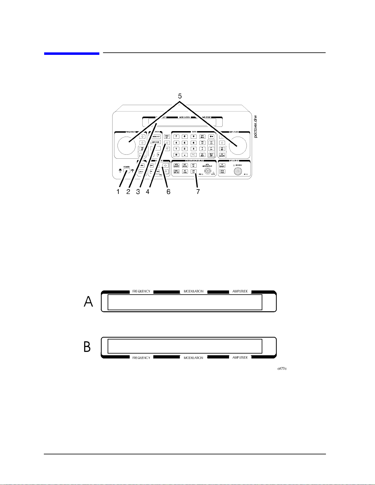
Figure 1-1. The 8648 Signal Generator
1. Power Key
Press POWER to powe r u p th e in strument. T h e i n strument pow ers up to the same state it
was in when power was turned off, except that the RF output will be turned off and the
digit-select arrow keys (⇐ and ⇒) will be reset to the least significant digit.
2. Display
The display can be one of two displays depending on the serial number prefix of your
instrument as illustrated below.
1-2
Page 15

Operation
Quick Overview
The following table describes the prefixes that apply to the various 8648 models equipped
with an LCD.
A. Liquid Crystal Display (LCD)
(labels located above the display)
8648A Prefix 8648B Prefix 8648C Prefix 8648D Prefix
3636A and below 3623A and below 3623A and below 3613A and below
3643U and below 3642U and below 3642u and below 3642U and below
The display contrast of the LCD can be achieved using the adjustment that is located on
the rear panel of these instruments. Note that this adjustment is only available for
instruments equipped with an LCD. It allows you to adjust the contrast of the LCD. Turn
the adjustment to optimize the display for viewing from most angles. If the display is
blank, first attempt to adjust the display contrast before returning the instrument for
service.
The following table describes the prefixes that apply to the various 8648 models equipped
with a VFD.
A. Vacuum Fluorescent Display (VCD)
(labels located below the display)
8648A Prefix 8648B Prefix 8648C Prefix 8648D Prefix
3636A and above 3623A and above 3623A and above 3613A and above
3643U and above 3642U and above 3642u and above 3642U and above
The VFD is a 2x40 display. The intensity of this display is at 100% and cannot be adjusted.
3. Function and Data Keys
The keys in the FUNCTION and DATA blocks allow you to enter values for setting the
frequency, amplitude, and modulation level of the RF output signal.
If Option 1EP is present, the
(ENCODER) mode and FM mode.
If Option 1EP i s pr esent and the s i gn a l g e n e ra tor is in the ENC ODER mode, the
key functions as a SHIFT key. This key lets you input alphabetical characters using the
DATA and MODULATION SOURCE blocks when you are in pager encoder mode.
If Option 1EP i s pr esent and the s i gn a l g e n e ra tor is in the ENC ODER mode, the
key functions as an ENTER key. The ENTER key must be used to store any numeric
dB(m)
or alphabetic characters entered b y way of the DATA and MODULATION source blocks.
FM (ENCODER) key will toggle between pager encoder
rad dBµV
MHz
1-3
Page 16

Operation
Quick Overview
4. Increment Set Keys
When you press a FUNCTION key, that function becomes the active function. Press INCR
SET to view or change the increment value fo r the active functi on. Press ⇑ or ⇓ at any time
to change the active funct ion setti ng by t he increment value. (If Option 1EP is pres ent and
the signal generator is in the ENCODER mode, these keys have alternate functions.)
If Option 1EP is present and the signal generator is in the ENCODER mode, the
INCR SET
key functions as a START/STOP key. This key starts or stops any pager encoding activity.
In addition, in this mode, the ⇑ and ⇓ function as PREV and NEXT keys. These keys let
you move the blinking cursor between each parameter when you are entering the pager
encoding settings.
5. Knobs
The knobs are always active when the instrument is in local (front panel) control. Turn
them to increase or decrease the frequency or the amplitude of the RF output. Press ⇐ or
⇒, next to each knob, to adjust the knobs resolution.
Press
turn on the reference mode . Press
REF SET, next to each knob, to s et the displayed value as the refere nce value and
REF ON/OFF to turn on and off the reference mode
without changing the reference value. When the reference mode is on, the displayed value
indicates th e of fset betwee n the referenc e v a l u e a n d the RF output signal.
If Option 1EP i s present and th e s i gn a l g e n e ra tor is in the E N C O DER mode, the
AMPLITUDE/ENCODER knob is used to enter a setting for a pager encoding parameter.
6. MEMORY
memory registers allow you to save instrument setups and recall them whenever you wish.
Press
To recall the settings, press
to recall registers in numerical sequence. You can arrange your registers in up to ten
different sequences.
SAV and enter a two-digit register number to save the instrument’s current settings.
REG and enter the register number. The arrow keys allow you
The number of the currently selected sequence and the last register selected are always
displayed in the lower -left corner of the display to help you keep track of where you are in
your testing process . (If Option 1EP is present, t he sequence and register are not d isplayed
on any pager encoding menu.) The memory register examples provided in Chapter 1a,
“Operation Examples,” show you how to create a sequence and how to delete or add
registers in your sequence.
1-4
Page 17

Operation
Quick Overview
7. Modulation Source
Press MOD ON /OF F to tu rn on or off the modulation so urce . Press INT 400 kHz or INT 1 kHz to
select one of the internal source tones for modulating the RF output signal. These tones
are also available as an output signal at the MOD INPUT/OUTPUT port when they are
selected. Press
INPUT/OUTPUT port.
EXT AC or EXT DC to ac- or dc-couple an external audio source via the MOD
Press
1kHz + EXT DC to frequency modulate the RF signal with the inter nal 1 kHz tone and
an external source at the same time. (Additional internal plus external modulation
capabilities are available for GPIB ope ration.)
1kHz + EXT DC will also amplitude or phase
modulate the RF signal with the internal 1 kHz tone but it will not be dc-coupled.
If Option 1EP is present, the
INT 1kHz (FREQUENCY/WAVEFORM) key scrolls between five states: a fixed 1 kHz
INT 1kHz (FREQUENCY) key, or if Option 1E2 is present, the
internal source and a variable-frequency internal source with four different waveform
selections. The four modulation waveforms are sine, triangle, square, and sawtooth (or
ramp).
1-5
Page 18

Operation
Quick Overview
1-6
Page 19

1a Operation Examples
This section contains operating examples to help you learn how to operate the signal
generator. These examples can be performed without any additional equip ment. The pager
testing example can only be performed if Option 1EP is present.
If this is the first time you have operated this instrument, perform each of the following
examples for a quick introduction to general operation. After you have completed the
examples, try operating the instrument’s remaining functions on your own. If you have
trouble or want additional information on a function, refer to Chapter 1b , “Operation
Reference.” If a message is displayed that you do not understand, ref er to Chapter 1c,
“Operation Messages.”
The item numbers of the following operation examples correspond to the numbers called
out on drawing of the instrument front panel.
1. Setting the RF Output Signal
2. Incrementing or Decrementing the RF Output Signal
3. Using the Memory Registers
4. Offsetting the RF Output from a Reference
5. Holding the Output Attenuator Range
6. Setting a User Selectable Modulated Frequency and Waveform (Option 1E2 or 1EP
Only)
7. Signaling a Numeric-Type FLEX Pager (Option 1EP Only)
1a-1
Page 20

Operation Examples
1a-2
Page 21

Operation Examples
Setting the RF Output Signal
Setting the RF Output Signal
In this example, you will set the frequency, amplitude, and modulation level of the RF
output signal.
Setting the Frequency
1. Set the frequency to 100 MHz using the keys shown below the instrument diagram.
If you make a mistake while entering a value, press ⇐ to correct it.
Setting the Amplitude
2. Set the amplitude to −100 dBm.
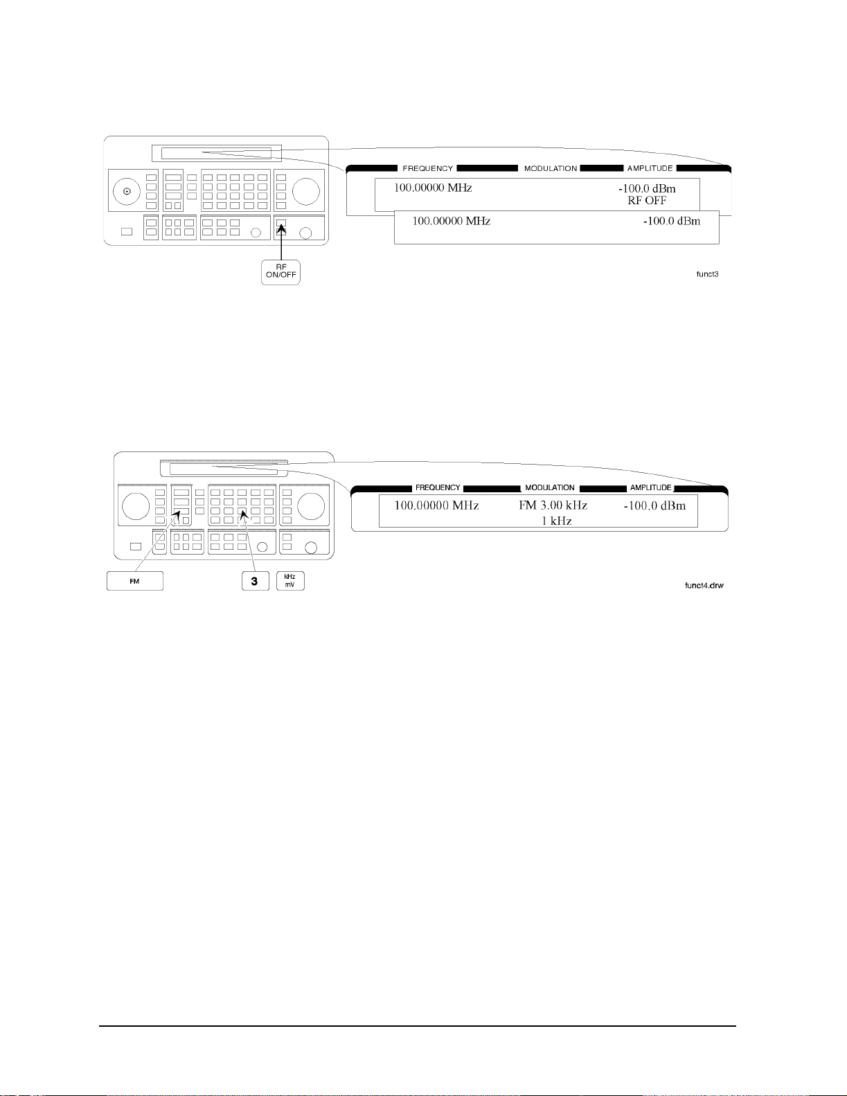
Turn on the RF Output
3. Press RF ON/OFF to turn on the RF output.
RF OFF is displayed below the amplitude setting when the RF output is turned off.
1a-3
Page 22
Operation Examples
Setting the RF Output Signal
Setting the Modulation
4. Set the FM deviation to 3 kHz.
The modulation rate is displayed below the deviation sett ing. Use the MODULATION
SOURCE keys to select a modulation source and turn modula tion on or off.
1a-4
Page 23

Operation Examples
Incrementing or Decrementing the RF output Signal
Incrementing or Decrementing the RF output Signal
In this example, you will increment the amplitude and frequency of the RF output signal.
Preliminary Steps
1. If they are not already set, set the frequency to 100 MHz and the amplitude to
−100 dBm.
Using the Knob
2. Increment the amplitude using the knob.
Press ⇐ or ⇒ when you wish to adjust the increment resolution.
Using the Increment Keys
3. Enter a frequency increment of 25 kHz
The symbol is displayed when you press
value is the increment set value.
INCR SET to indicate that the displayed
1a-5
Page 24

Operation Examples
Incrementing or Decrementing the RF output Signal
4. Increment the Rf output frequency in 25 kHz steps.
The increment keys affect the last FUNCTION selected (FREQUENCY, AMPLITUDE,
FM, AM, OR φM).
1a-6
Page 25
Operation Examples
Using the Memory Registers
Using the Memory Registers
The memory register examples show you how to crate a sequence of registers, delete a
register from that sequence, renumber the registers in the sequence, and insert a new
register in the sequence.
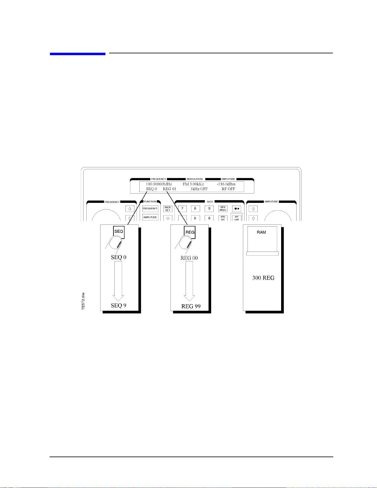
Up to 10 register sequence s can be def ined (0 through 9) . A s equence can cont ain up t o 10 0
registers (00 through 99). There are a total of 300 registers available in the instrument.
The registers can be used in the sequences in any combination 9such as 10 sequence s of 30
registers each, or 3 sequences of 100 registers each) as long as the total does not exceed
300 registers. It is not possible to have all 10 sequences each contain 100 registers as that
would be 1000 registers. (If Option 1EP is present, there are a total of 70 registers
available.)
1a-7
Page 26

Operation Examples
Using the Memory Registers
Saving Instrument Setting in Register Sequences
In this ten step example, you will use the memory keys to create a sequence containing
three registers. Each register will contain a different frequency setting.
Selecting the Sequence
1. Select sequence 0.
If there are registers saved in sequence 0, the message shown in the display below will
not appear. Note that the steps in this example will cause the settings in registers 00,
01, and 02 of sequence 0 to be changed.
Saving Settings in Registers
2. Set the frequency to 10 MHz.
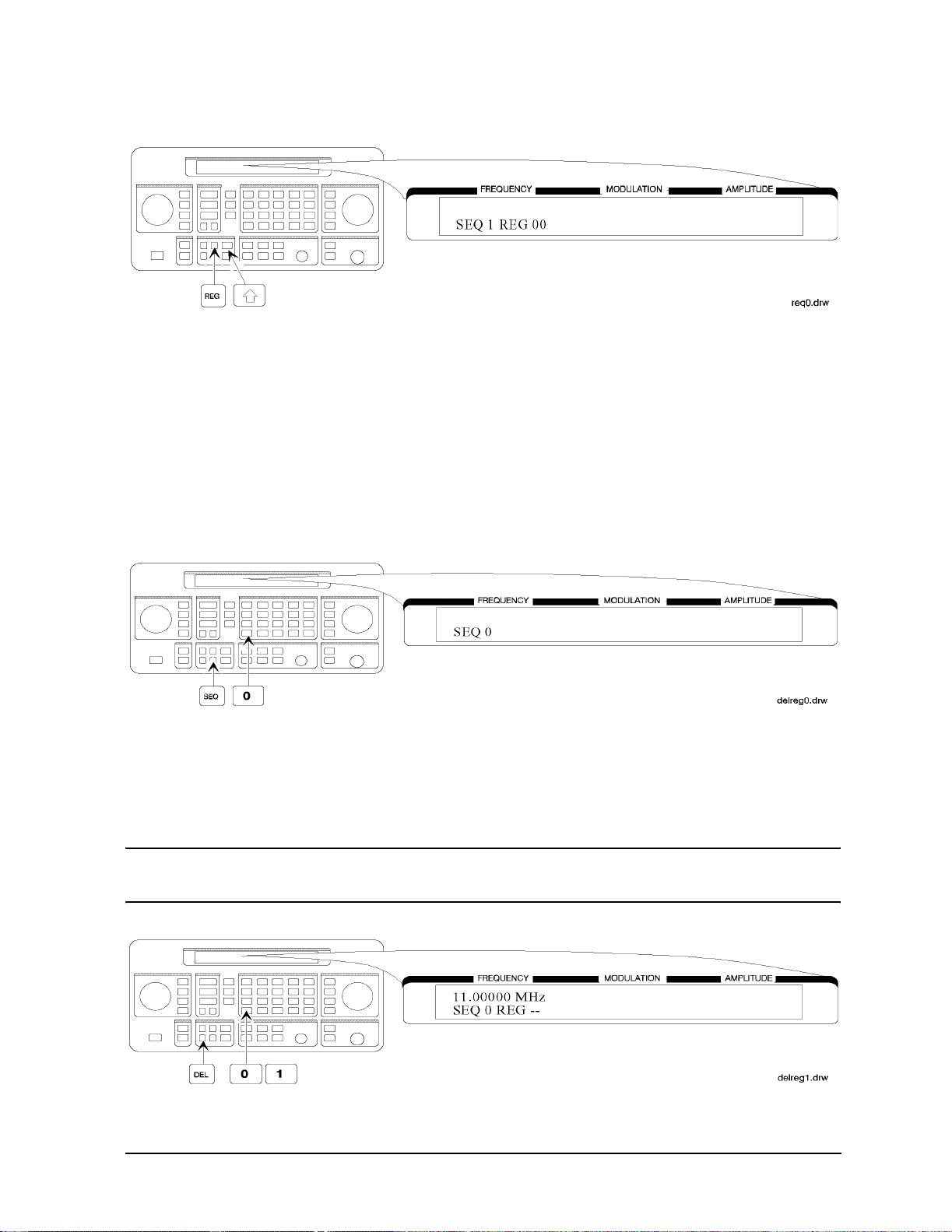
3. Save the instrument settings in register 00.
1a-8
Page 27

4. Set the frequency setting to 11 MHz.
5. Save the instrument settings in register 01.
Operation Examples
Using the Memory Registers
6. Set the frequency to 12 MHz.
7. Save the instrument settings in register 02.
1a-9
Page 28
Operation Examples
Using the Memory Registers
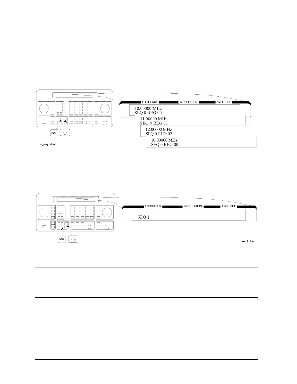
Checking the Sequence
8. Recall the registers in sequence 0.
The ⇑ and ⇓ keys recall registers or sequences dep ending on which key was press ed last
(
REG or SEQ).
Checking a Different Sequence
9. Select sequence 1.
10.Step through the registers in sequence 1 if there are registers saved in it.
NOTE Sequence 1 does not contain the settings you saved in sequence 0. The
instrument enables you to save different sett ings in eac h sequence to create
up to ten different sequences for your testing. Remember when you save or
recall a register, be sure that the correct sequence is also selected.
1a-10
Page 29
Operation Examples
Using the Memory Registers
Deleting a Register from the Sequence
In this example, you will delete a register from the sequenc e you created in the preceding
example.
Selecting the Sequence
1. Select sequence 0.
Deleting a Register
2. Delete register 01 from sequence 0.
NOTE The contents of the register are recalled when i t is d eleted. This a llows you t o
re-save the contents if you need to.
1a-11
Page 30
Operation Examples
Using the Memory Registers
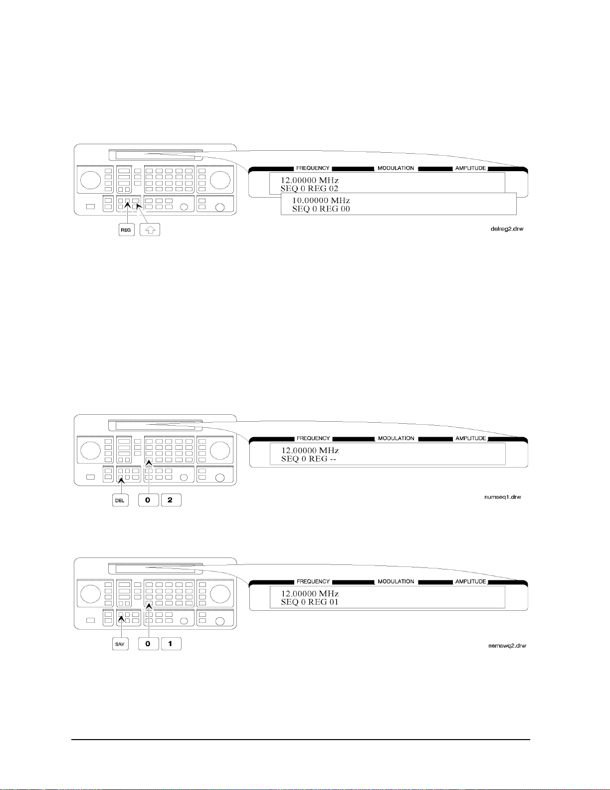
3. Step through the remaining registers in sequence 0.
The deleted register number has been removed from the sequence. Note that the
instrument does not renumber the registers when one is deleted.
Renumbering the Registers in a Sequence
In this example, you will eliminate the skip from register 00 to register 02 in sequence 0
caused when you deleted register 01 in the previous example.
Decreasing the Register Number
1. Delete register 02.
The settings saved in register 02 are recalled when it is deleted.
2. Save the se tt i n g s from register 0 2 in t o re g i s te r 01.
1a-12
Page 31

Operation Examples
Using the Memory Registers
Checking the Sequence
3. Step through the register sequence.
NOTE In this example, you renumbered one register. when you need to renumber
two or more registers, use
REG instead of DEL to recall each register until you
get to the last register in the sequence, then us e DEL.
Inserting a Register in a Sequence
In this example, you will insert a register into the sequence you created in the previous
example. The process involves incrementing eac h regist er number that comes after the
point in the sequence where you wish to insert a register.
1. Recall the last register in sequence 0.
2. Save the recalled settings into register 02.
1a-13
Page 32

Operation Examples
Using the Memory Registers
3. Recall register 00.
Register 01 can now be used to save the settings that are saved in register 00.
4. Save the recalled settings into register 01.
Register 00 can now be used to save the new settings.
Saving a New Register
5. Set the frequency to 8 MHz.
1a-14
Page 33

6. Save the settings in register 00.
Press ⇑ to check the new sequence.
Operation Examples
Using the Memory Registers
1a-15
Page 34

Operation Examples
Offsetting the RF Output from a Reference
Offsetting the RF Output from a R eference
In this example, you will enter an RF output frequency, set it as the reference value, and
then offset the RF output frequency 10 MHz below the reference value.
Setting the Reference Value
1. Set the frequency to 500 MHz.
2. Set 500 MHz as the reference frequency.
The ∆ symbol appears in the di spla y to indicate that the refere nce mode is selec ted. The
output frequency is still 500 MHz.
1a-16
Page 35

Operation Examples
Offsetting the RF Output from a Reference
Offsetting the RF Output
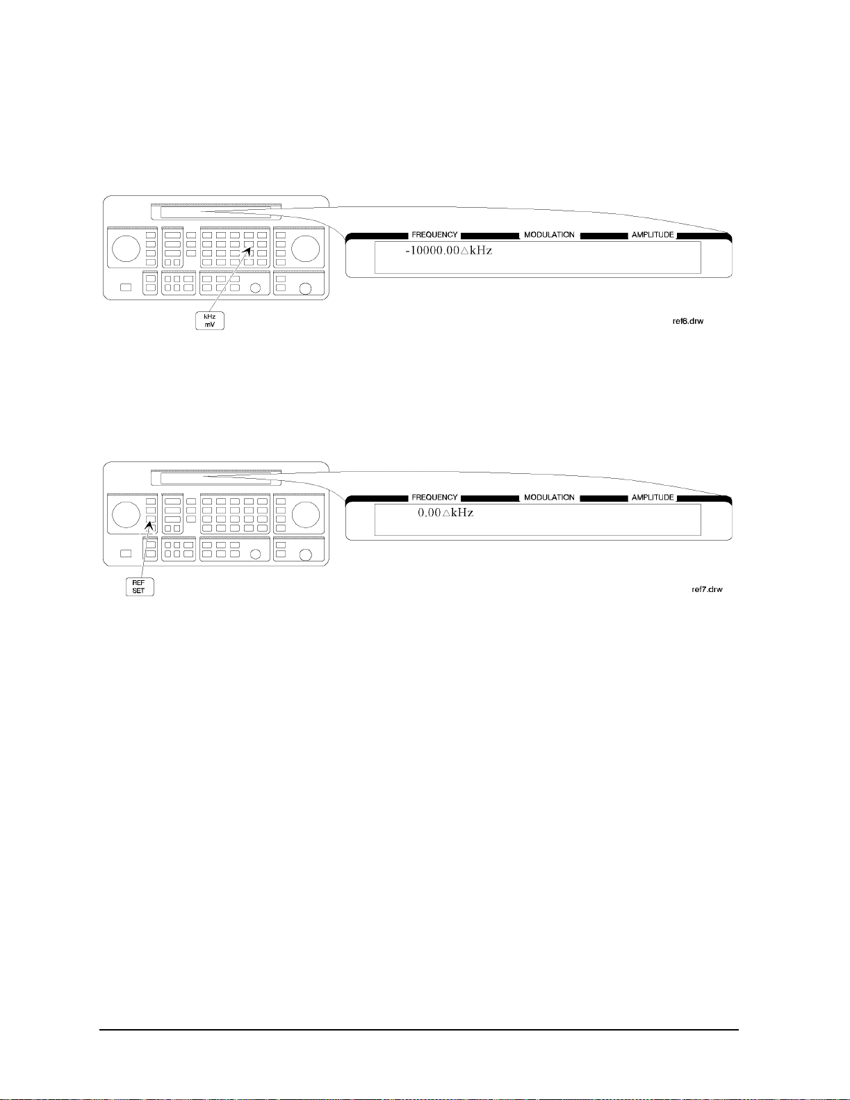
3. Offset the output frequency 10 MHz below the reference frequency.
You can enter in the offset value directly, or use the knob or ⇑ and ⇓ keys.
Atttention! In the reference mode, the output frequency equals the refe rence frequency ±
the displayed offset frequency.
Turning the Reference Mode Off or On
4. Turn off the reference mode to display the actual output frequency.
5. Turn on the reference mode without changing the reference frequency.
1a-17
Page 36
Operation Examples
Offsetting the RF Output from a Reference
6. Change the displayed units to kHz.
Note that for amplitude, reference settings are displayed in dB units only.
Setting a New Reference Value
7. Set the current output frequency as the new reference frequenc y at any time.
1a-18
Page 37

Operation Examples
Holding the Output Attenuator Range
Holding the Output Attenuator Range
In this example, you will hold the output atte nuator so it d oes not c hange ranges when you
change the amplitude setting. This will prevent attenuator range changes from affecting
the output signal.
Set the Amplitude Level
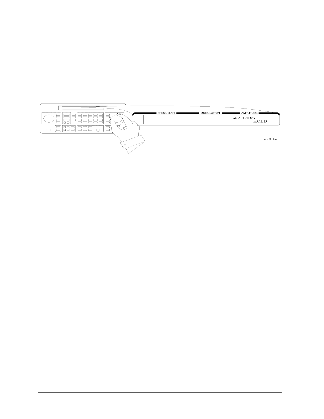
1. Set the amplitude level to −82 dBm.
Holding the Attenuator
2. Hold the attenuator at this setting.
1a-19
Page 38
Operation Examples
Holding the Output Attenuator Range
Adjusting the Amplitude
3. Adjust the amplitude setting.
Now amplitude changes do not cause the attenuator to change its range setting.
Consequently, amplitude changes are limited to the range provided by the instrument’ s
vernier. For information about the instrument’s vernier ranges, refer to Chapter 1b,
“Operation Reference.”
1a-20
Page 39

Operation Examples
Setting a User Selectable Modulated Frequency and Waveform (Option 1E2 or 1EP Only)
Setting a User Selectable Modulated Frequency and
Waveform (Option 1E2 or 1EP Only)
NOTE This modulation example can only be performed if Option 1E2 or 1EP is
present.
In this example, you will select the modulation level and the modulated frequency and
waveform of the RF signal output.
Setting the Modulation Level
1. Select FM modulation with a deviation of 25 kHz.
Either
or ΦM) and the modulation level (deviation or depth) is displayed on the top line of the
front panel display as shown.
AM or ΦM modulation may be used instead of FM. The modu latio n typ e (FM, AM,
Setting the Modulated Waveform
2. Press the INT 1kHz (FREQUENCY/WAVEFORM) key until SQU is selected.
Repetitively pressing the
states:
• a fixed 1 kHz sinewave internal source
• a variable-frequency sinewave source (indicated by SIN preceded by the frequency
value)
INT 1kHz (FREQUENCY/WAVEFORM) key selects one of five
• a variable-frequency triangle source (TRI)
• a variable-frequency squarewave source (SQU)
• a variable-frequency sawtooth (or ramp) source (SAW)
1a-21
Page 40

Operation Examples
Setting a User Selectable Modulated Frequency and Waveform (Option 1E2 or 1EP Only)
Setting the Modulated Frequency
3. Set the modulated frequency to 1.5 kHz.
kHz key is the only accepted units key.
The
1a-22
Page 41

Operation Examples
Signaling a Numeric-Type FLEX Pager (Option 1EP Only)
Signaling a Numeric-Type FLEX Pager (Option 1EP Only)
In this example you will set up the pager encoder to send a signal appropriate to test a
numeric-type FLEX pager.
NOTE This pager encoding example can only be performed if Option 1EP is present.
The front panel of the Option 1EP instrument is diffe rent from the standard
instrument’s front panel. The green and blue labels are incorporated for the
pager encoding mode only. Therefore, these keys have multiple functions on
instrument s wi th O p ti o n 1E P.
Figure 1a-1. The 8648A Option 1EP Signal Gene rator
Setting Up Pager Encoding
The following steps are required to set up pager encoding on the signal gener ator. Details
of setting each parameter are provided following this overview.
1. Before entering the signal generator pager encoder mo de, set the correct carrier
frequency and FM deviation for the pager-under- test. (The FM deviation is 4.8 kHz for
FLEX and is 4.5 kHz for POCSAG.)
2. Press RF ON/OFF to turn on the RF output. (RF OFF is displayed below the amplitude
setting when the RF output is turned off.)
3. Enter the pager encoder mode by pressing FM (ENCODER). If FM wasn’t the last
active function, press FM (ENCODER) twice.
4. Set up the pager encoder parameters to meet the test requireme nts of your specific
pager.
1a-23
Page 42

Operation Examples
Signaling a Numeric-Type FLEX Pager (Option 1EP Only)
Use the ⇓ (NEXT) and ⇑ (PREV) keys to scroll through the encoder parameters. The
cursor will blink around the first letter of the active parameter. The ⇓ (NEXT) key
moves forward sequentially through each pager encoder parameter and the ⇑ (PREV)
key moves backward sequentially.
To move between setting for each parameter, rotate the AMPLITUDE/ENCODER knob
until the desired setting is displayed. When characters are entered by wa y of the
keypad (such as the capcode), terminate the entr y with the
MHz dB(m) (ENTER) key.
5. Start signaling the pager after all of the encoder parameters are set by pressing the
INCR SET (START/STOP) key.
Entering Pager Encoding Settings
1. Display the first pager encoder menu.
After setting your pager’s carrier frequency and an FM deviation of 4.8 kHz (for a FLEX
pager) on the signal generator, press the
first pager encoder menu (FORMAT). The
frequency modulation menu and the pager encoder menu.
FM (ENCODER) key once again to display the
FM (ENCODER) key toggles between the
Selecting the Format Settings
2. Set FORMAT to FLEX, POLARITY to NORMAL, and FILTER to ON.
a. With the blinking cursor on the “F” of FORMAT, set the FLEX format by rotating the
AMPLITUDE/ENCODER knob until FLEX is displayed.
b. Press th e ⇓ (NEXT) key to move the blinking cur s o r to POLARITY, then use the
AMPLITUDE/ENCODER knob to set the polarity to NORMAL.
c. Using the ⇓ (NEXT) key and the AMPLITUDE/ENCODER knob, set FILTER to ON.
1a-24
Page 43

Operation Examples
Signaling a Numeric-Type FLEX Pager (Option 1EP Only)
Selecting the Data Rate and Pager Type Settings
3. Set DATA RATE to 3200/2 and PAGER TYPE to NUMERIC, using the
AMPLITUDE/ENCODER knob and the ⇓ (NEXT ) ke y.
You may choose to set the data rate to one of the other settings; you FLEX pager should
automatically adjust.
Press the ⇓ (NEXT) key to move to the next page.
4. Set VECTOR TYPE to STANDARD using the AMPLITUDE/ENCODER knob.
Press the ⇓ (NEXT) key to move to the next page.
1a-25
Page 44

Operation Examples
Signaling a Numeric-Type FLEX Pager (Option 1EP Only)
Selecting the Message Settings
5. You may choose one of the f ive fixed mes sages ( only number s one and five are us eful fo r
numeric pagers) or you may define your own message. For this example, us e your own
phone number as the user-defined message:
a. Set MESSAGE NO. to 6 and MESSAGE LENGTH to 40 using the
AMPLITUDE/ENCODER knob and the key.
b. Press th e ⇓ (NEXT) key again to select the FREE MESSAGE parameter.
c. Enter your phone number with the numeric keys and terminate your entry with the
MHz dB(m) (ENTER) key.
Press the ⇓ (NEXT) key to move to the next page.
Selecting the Transmission Repetitions and Amplitude
6. Set MODE to SINGLE and AMPLITUDE to 0.0 dBm using the AMPLITUDE/ENCODER
knob and the ⇓ (NEXT) key. Enter the numeric values using the numeric keys and the
MHz dB(m) (ENTER) key.
Press the ⇓ (NEXT) key to move to the next page.
1a-26
Page 45

Operation Examples
Signaling a Numeric-Type FLEX Pager (Option 1EP Only)
7. Set IMMEDIATE STOP to OFF, HEADER to ON, and TERMINATOR to ON using
AMPLITUDE/ENCODER knob and the key. These are default settings that normally
would not be adjusted.
Press the ⇓ (NEXT) key to move to the next page.
Selecting the Pager Capcode (Address)
8. Enter your pager’ s capcode (address) in the pager code menu. The rad dBµV (SHIFT) key
is required to enter alphabetical characters. For example, to enter the following
capcode: A0012477, press,
(NEXT) key and the AMPLITUDE/ENCODER knob, set DUMMY CALL to OFF.
7 (A), 0012477, MHz dB(m) (ENTER). Then, using the ⇓
NOTE The pager’s capcode contains information that automatically sets the
parameters of the last two menus.
Press the ⇓ (NEXT) key to move to the next page.
1a-27
Page 46

Operation Examples
Signaling a Numeric-Type FLEX Pager (Option 1EP Only)
9. ADDRESS TYPE and ADDRESS1 are set automatically when th e capco de is ent ered in the
previous menu. If A0012477 was entered, SHORT and 0045245 would be displayed
respectively. Generally, you would not change these settings.
Press the ⇓ (NEXT) key to move to the next page.
Selecting the Protocol Settings
10.FRAME, PHASE, and COLLAPSE CYCLE are also set automatically when you enter the
pager’s capcode. If you entered A0012477 previously, 011, D, and 4 would be displayed.
NOTE If MODE is set to BURST or CONT instead of SINGLE, you may choose to change
the collapse cycle to 1 to 7. With a collapse cycle of 4, the pager will receive
the message once every 16 frames (2
4
). If the collapse is 0 or 1, the pager will
receive the message either every frame (20), or every other frame (21).
Press the ⇓ (NEXT) key to move to the next page.
1a-28
Page 47

Operation Examples
Signaling a Numeric-Type FLEX Pager (Option 1EP Only)
Selecting the Roaming Mode Settings
11.Set ROAMING MODE to NONE using the AMPLITUDE/ENCODER knob.
Press the ⇓ (NEXT) key to move to the next page.
Encoding
12.To start encoding aft e r selecting all pa g e r e ncoder para me ters, press the INCR SET
(START/STOP) key.
1a-29
Page 48

Operation Examples
Signaling a Numeric-Type FLEX Pager (Option 1EP Only)
1a-30
Page 49

1b Operation Reference
This chapter describes each of the instrument’s functions including all of the front panel
keys, the rear panel connectors, and the optional remote interface and memory interface.
This information is presented in the same functional groups as the front panel key
functional groupings.
NOTE Option 1EP adds a pager encoder capability to the standard functions.
Consequently the front panel of the Option 1EP instrument is dif ferent from
the standard instrument’s front panel. The green and blue labels are
incorporated for the pager encoding settings onl y. Therefore these keys have
multiple functions on instruments with Option 1EP.
1b-1
Page 50

Operation Reference
Frequency and Amplitude
Frequency and Amplitude
The knob and reference set keys work similarly for both freq uency and amplitude settings.
1. Knob
Turn the knobs to increment or decrement the frequency and amplitude s ettings. The
knobs are always active when the instrument is in local operation.
If Option 1EP i s pr e s e n t a n d th e s i gn a l g e n e ra t or is in the ENCO DER mode, the knob in
the AMPLITUDE/ENCODER block is used to select the desired setting for each pager
encoder parameter.
2. Digit-Select Arrow Keys
Press these digit-select arrow keys (⇐ ⇒)to select the digit to be changed with the knob.
NOTE The knobs increment the selected digit only. For information about
incrementing by an arbitrary value using the increment set keys, see
“Increment Set” in this chapte r.
3. REF SET
Press REF SET to turn on the re fe re nce mode and to se t t he cu r rent RF outpu t se t ti n g a s
the reference value. The refere nce val ue is s tored in non-vol atile memory unt il you replace
it by pressing
REF SET again.
When you press
∆ appears, the displ a yed valu e ind icates the offs et between the ref erence val ue and the RF
output signal.
1b-2
REF SET, the ∆ symbol is displayed between the value and the units . When
Page 51

The RF output signal is not changed when you press this key.
Units
Operation Reference
Frequency and Amplitude
When you press
REF SET for frequency, values can be entered in MHz or kHz. For
amplitude, values can be entered in any of the amplitude units provided, but they are
displayed in dB only.
4. REF ON/OFF
Press REF ON/OFF to turn off the refer ence mode if it is on, or to turn on the refer ence mode
without changing the reference value.
When you turn on the reference mode, the displaye d value indicates the of fset betw een the
reference value and the current RF output setting.
The RF output signal is not changed when you press this key.
Output Power Trouble? If the RF output power seems too low, look for ∆ in the display
between th e power level va l ue and the dB ind i ca t or. The ∆ tells
you that reference mode is turned on. The displa yed value is not
the output power level; it is the of fset between the reference value
and the output power. To exit the reference mode, press
REF ON/OFF. Yo u can then reset the output power to the desired
level.
1b-3
Page 52

Operation Reference
Function
Function
1. FREQUENCY
The RF output frequency range for each model is shown in the following table. When
making frequency changes, the instrument does not turn off the RF output. However, the
power does blank for a few milliseconds when crossing the frequencies at 249, 501, 1001,
1260, 1600, 2001, 2520, and 3200 MHz.
Model Frequency Range
8648A 100 kHz to 1000 MHz
8648B 9 kHz to 2000 MHz
8648C 9 kHz to 3200 MHz
8648D 9 kHz to 4000 MHz
Frequency switching typically takes less than 75 ms at frequencies lower then 1001 MHz,
and less than 100 ms at higher frequencies.
1b-4
Page 53

Operation Reference
Function
2. AMPLITUDE
The RF output amplitude range is shown in the following table. When making amplitude
changes, the instrument does not turn off the RF output. The period of any over- or
under-ranging that may occur during level transitions is typically less than 30 ms.
Output Amplitude Ranges
Model Frequency Range Amplitude
8648A 100 kHz to 1000 MHz +10 to −136 dBm
8648B/C/D ≥ 2500 MHz
> 2500 MHz
8648B/C/D
with Option 1EA
< 100 kHz
≤ 1000 MHz
≤ 1500 MHz
≤ 2100 MH
≤ 2500 MHZ
> 2500 MHz
Z
+13 to −136 dBm
+10 to −136 dBm
+17 to −136 dBm
+20 to −136 dBm
+19 to −136 dBm
+17 to −136 dBm
+15 to −136 dBm
+13 to −136 dBm
3. FM, AM, ΦM
Press FM to set the peak deviation for fr equenc y modulation. The n use t he data ent ry keys
to enter the desired value of deviation. The values allowed depend on the RF frequency
selected. See Chapter 4, "Specifications" for peak deviation specifications.
Press
desired value of range. Values from 0 through 100% are allowed.
Press
enter the desired value of deviation. The values allowed depend on the RF frequency
selected. See Chapter 4, "Specifications" for peak deviation specifications.
AM to set the amplitude modulation range. Then use the data entry keys to set the
FM to set the peak deviation for phase modulation. Then use the data entry keys to
1b-5
Page 54
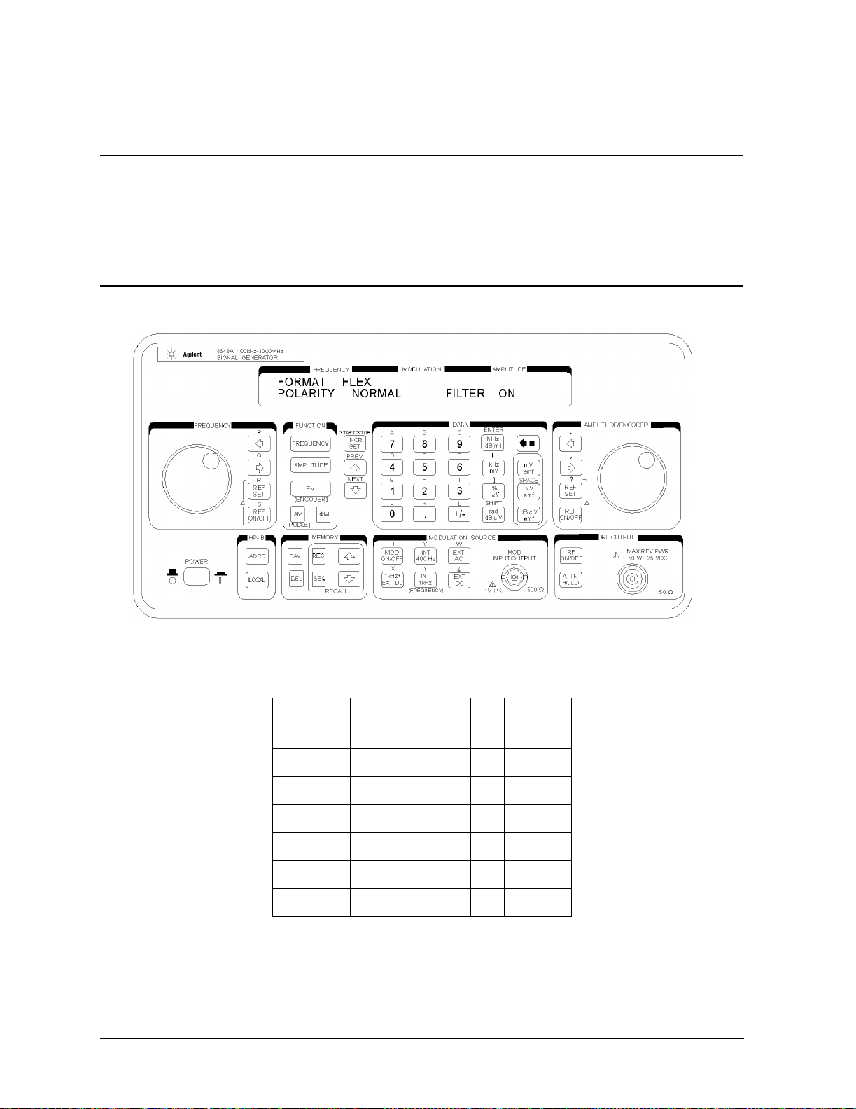
Operation Reference
Function
Setting Up the Pager Encoder
NOTE The pager encoder mode is available only on instruments with Option 1EP.
Option 1EP adds pager encoding/signaling capabilities to the stand ard
functions. Consequently the front panel of the Option 1EP instrument is
different from the standard instr ume nt’s front panel. The green and blue
labels are incorporated for the pager encoding settings only. Therefore, these
keys have multiple functions on instruments with Option 1EP.
Figure 1b-1. 8648A Option 1EP Signal Generator
For numeric mess ages, the following keys are assigned for the special character s in
addition to the standard numeric keys (0 to 9).
Front
Panel Key
S Spare 1010
U U 1011
Space Space 1100
- - (Hyphen)1101
] ] 1110
[ [ 1111
1b-6
Character B3B2B1B0
Page 55

1. ENCODER
Operation Reference
Function
NOTE Before selecting the pager encoder mode, check that the correct pager carrier
frequency and FM deviation have been set.
To select the pager encoder mode, press
FM (ENCODER) tw i ce : on ce to set FM deviat io n ,
then again to toggle between the standard functions and the pager encoder mode. The
display will look like the following:
This format menu is alway s dis played first when the pager encoder mode is selected.
The ⇑ (PREV) and ⇓ (NEXT) keys are used to move the blinking cursor between each
parameter.
The knob in the AMPLITUDE/ENCODER block is used to select the desired setting for
each pager encoder parameter.
To start or stop encoding, press
INCR SET (START/STOP).
1b-7
Page 56

Operation Reference
Function
Setting the Format
The format menu, shown in the previous figure, has the fo llowing set tings :
• FORMAT selects the pager protocol being tested.
FLEX: FLEX format
FLEX-TD: FLEX-TD format
POCSAG: POCSAG format
PN15: Pseudorandom Sequence (PN15)
RESYNC: Re-synchronization function (for FLEX/FLEX-TD pagers only)
SERVICE: Servicing the 8648A Option 1EP
• POLARITY selects the data polarity.
Normal: Normal polarity
POCSAG FLEX/FLEX-TD
(2-Level FSK),
RESYNC, PN15
“1”: Carrier − Deviation “1”: Carrier + Deviation “10”: Carrier + Deviation
“0”: Carrier + Deviation “0”: Carrier − Deviation “00”: Carrier − Deviation
FLEX/FLEX-TD
(4-Level FSK)
“11”: Carrier + (Deviation/3)
“01”: Carrier − (Deviation/3)
INVERSE: Inverse polarity
POCSAG FLEX/FLEX-TD
(2-Level FSK),
RESYNC, PN15
“1”: Carrier + Deviation “1”: Carrier − Deviation “10”: Carrier − Deviation
“0”: Carrier − Deviation “0”: Carrier + Deviation “00”: Carrier + Deviation
FLEX/FLEX-TD
(4-Level FSK)
“11”: Carrier − (Deviation/3)
“01”: Carrier + (Deviation/3)
• FILTER selects whether or not the baseband modulation filter (10th-order Bessel
low-pass filter, −3 dB at 3.9 kHz) is used. Normally the filter is on.
ON: Uses the low-Pass filter
OFF: Does not use the low-pass filter
1b-8
Page 57

Operation Reference
Function
FLEX/FLEX-TD
Setting the d ata Rate and Pager Type
The parameter menu for the data rate and the pager type looks like the following:
• DATA RATE specifies how fast the data stream is output in bits per second and whether it is
2-level or 4-level FSK.
1600/2: 1600 bps, 2-level FSK
3200/2: 3200 bps, 2-level FSK
3200/4: 3200 bps, 4-level FSK
6400/4: 6400 bps, 4-level FSK
• PAGER TYPE specifies the type of message a pager under test can respond to and is selectable
from the following:
TONE ONLY: Short Message/Tone only type
NUMERIC: Numeric type
ALPHANUMERIC: Alphanumeric type
HEX/BIN: HEX/Binary type
If NUMERIC is selected, the next setting to be selected is VECTOR TYPE as shown:
• VECTOR TYPE identifies the type of message as follows:
STANDARD: The pager-under-test displays the numeric message it receives .
SPECIAL: The pager-under-test converts the numeric message to a pre-defined message
which is displayed.
NUMBERED: The message numbers are assigned for each paging address separately
starting at 0 and progressing up to a maximum of 63 in consecutive order.
1b-9
Page 58

Operation Reference
Function
If NUMBERED is selected, the next parameter to be selected is NUMBER as follows.
NUMBER is for setting the initial number of the numbered numeric message that will be transmitted.
The allowable range is 0 to 63.
If HEX/BIN is selected, the next setting to be selected is BLOCKING LENGTH:
• BLOCKING LENGTH indicates the bits per character as follows:
1BIT: 1 bit per character
7BITS: 7 bits per character
8BITS: 8 bits per character
14BITS: 14 bits per character
16BITS: 16 bits per character
Enter the message in the hexadecimal format to the MESSAGE NO. 6 in the message menu.
NOTE When 7BITS or 14BIT S are selected, the total number of hexadecimal characters of
the message must be a multiple of 7 characters (28 bits).
Setting the Message The message menu looks like the following:
1b-10
Page 59

Operation Reference
• MESSAGE NO. is defined as the following where “X” represents the phase setting:
0: Arbitrary message set from the external controller using the GPIB capability.
The data must be entered in units of works. Refer to
‘[SOURce]:PAGing[:FORMat]:{POCSag|FLEX|FTD}:ARBitrary:
DEFine <NR1>, <NR2>,..., <NR1>” and “Using the Buffer Memory for the
Arbitrary Messages” in Chapter 2.
START FRAME and STOP FRAME are defined in the following menu:
The frames between the START FRAME and STOP FRAME will be transmitted. The allowable
ranges for both are 000 to 127.
Function
1: Displays: 01223456[X}
where “X” = “0” for phase A, "1" for phase B, “2” for phase C, “3” for phase D.
2: Displays: ABCDEFG[X}
where “X” = phase “A”, “B”, “C”, “D”.
3: Displays: TEST PAGING: XXXXXXX
where “XXXXXXX” = “PHASE A”, “PHASE B”, “PHASE C”, or “PHASE D”.
4: Displays: ALPHANUMERIC 40CHARS TEST PAGING:X XXXXXX
where “XXXXXXX” = “PHASE A”, “PHASE B”, “PHASE C”, or “PHASE D”.
5: Displays: 888888888888 88888888 888888 88888888 888888
for LCD test with 50 characters of “8”
6: User-definable message, up to 40 characters long, set from the front panel.
Enter numeric messages with t he keypad. Alph anumeric mess ages require the
rad dBµV (SHIFT) key t o ac cess t he a lphab eti cal c hara cte rs ( blue lett ers) abov e
the keypad. If required alphabetic al characters are not available on the front
panel, send a message from an external controller over GPIB. Refer to
“[SOURce]:Paging[:FORMat]
:{POCSag\FLEX|FTD}:MESS:DEFine ‘string’” in Chapter 2.
• MESSAGE LENGTH specifies the maximum number of characters that will be sent out and
displayed in the message field. The allowable range is 1 to 40. After specifying the number of
characters, press
MHz dB(m) (ENTER) to save the new value.
When the value of this parameter is equal to or greater than the length of the message, the
whole message will be sent out.
When the value of this parameter is less than the length of the message, only the characters
specified by this parameter are output. (For example, if the MESSAGE NO. is 1 (0123456[X]) and
the MESSAGE LENGTH is 5, the message which is displayed and will be sent out is actually 01234.)
1b-11
Page 60

Operation Reference
Function
Setting the Encoding Mode The number of times a message is transmitted and the level of that
transmission are determined by the following menu:
• MODE determines whether the message will be output once or multiple times when
INCR SET
(START/STOP) is pressed.
SINGLE: Outputs the message once.
BURST: Outputs the message the number of times specified in the BURSTS field (3
times in this example).
CONT: Outputs the message continuously unti l the
INCR SET (START/STOP) key is
pressed a second time. (Note: The collapse cycle described later on in this
section will determine how often the message will be transmitted per cycle.)
• AMPLITUDE sets the output signal level of the carrier.
• BURSTS sets the number of times the message will be transmitted. This parameter is displayed
only when the MODE parameter is set to BURST. The allowable range is 1 to 256.
• RF OFF is displayed below the amplitude setting when the RF output is turned off. To toggle the
RF signal output on and off, press
RF ON/OFF.
• HOLD is displayed when the step attenuator is held at its current range setting. To toggle the
attenuator hold function on and off, press
ATTN HOLD.
Another menu is displayed as follows for completing the Encoding Mode:
• IMMEDIATE STOP terminates pager signaling as follows when a stop event occurs.
ON: Te rminates pager signaling immediately.
OFF: Default setting. Terminates pager signaling just before the next instance the
pager is on. (If TERMINATOR is set to ON, the pager encoder generates the
re-synchronization pattern in the frame that was supposed to contain the
message.)
• HEADER sets whether the idle frame signal is output in the frame before the first message.
ON: Default setting. Outputs the idle frame signal.
OFF: Does not output the idle frame signal.
1b-12
Page 61

Operation Reference
Function
• TERMINATOR sets whether the re-synchronization pattern is output after the last message. The
collapse cycle will determine in which frame the re-synchronization pattern appears after the
INCR SET (START/STOP) key is pressed to stop or at the end of a burst sequence (refer to
“FLEX/FLEX-TD Signaling Examples”).
ON: Default setting. Outputs the re-synchronization pattern.
OFF: Does not output the re-synchronization patt ern.
NOTE If TERMINATOR is set to OFF, the pager under test is not synchronized. Therefore, the
pager can not be synchronized with the future page until the re-synchronization
pattern is sent. To send the re-synchronization pattern, set TERMINATOR to ON in this
menu or select RESYNC in the format menu.
Entering the Pager Capcode (Address) The pager code menu looks like the following:
• PAGER CODE accepts alphanumeric characters up to 16 digits.
Use the numeric keys to enter the capcode. To select an alphabetical character, press
rad/dBµV
(SHIFT) before the numeric key associated with the desired alphabetic character. Terminate
your entry with the
MHz/dB(m) (ENTER) key.
A FLEX/FLEX-TD page r’ s capcode con tains addr ess and protocol information. Entering the cap code
in the PAGER CODE data field automatically sets up the ADDRESS TYPE, ADDRESS1, and
ADDRESS2 in the address menu, and the FRAME, PHASE, and COLLAPSE CYCLE in the
protocol menu as well.
The following tabl e sho ws an e xa mpl e of the co nvers i on fro m capcode s t o the parame te rs. Note that
the values of COLLAPSE CYCLE and FRAME are changed.
Capcode ADDRESS
TYPE
ADDRESS1 ADDRESS2 FRAME PHASE COLLAPSE
CYCLE
A0012477 SHORT 0045245 None 011 D 4
2A0012477 SHORT 0045245 None 011 D 2
1272A0012477 SHORT 0045245 None 127 D 2
1b-13
Page 62

Operation Reference
Function
• DUMMY CALL inserts a message with all 5s in all non-call phases. This is required by the
FLEX-TD standard (RCR STD-34A) for sensitivity testing.
ON: Default setting. Activates the dummy call function for equalizing the FSK
deviation. An address for the non-call phases must be set.
OFF: Does not activate the dummy call function. Idle frames are set in the non-call
phases.
The address menu will display the following information:
• ADDRESS TYPE selects the address length.
SHORT: Short address
LONG: Long address
• ADDRESS1 is the 7-digit short address or the primary address of the long address.
• ADDRESS2 is the 7-digit secondary address of the long address. (This is displayed o n ly when
ADDRESS TYPE is set to LONG.)
If DUMMY CALL is ON, the following address menu is displayed.
• ADDRESS TYPE (DUMMY CALL) displays the address type used in the non-call
phases (automatically set).
SHORT: Short address
LONG: Long address
• ADDRESS1 is the 7-digit short address or the primary address of the long address.
• ADDRESS2 is the 7-digit secondary address of the long address. (This is displayed o n ly when
ADDRESS TYPE (DUMMY CALL) is LONG.)
NOTE To equalize the FSK deviation, the addresses for DUMMY CALL should contain an equal
number of “1” and “0”.
1b-14
Page 63

Operation Reference
Function
Setting the Protocol The protocol menu displays the following information when “A0000001” is
the previously entered capcode.
These parameters, except for CYCLE , are all automatically set when the capcode is entered in the
PAGER CODE data field.
• CYCLE: Defines the start cycle. The allowable range is 0 to 14.
• FRAME: Defines the start frame where the message is located. The allowable range is 0 to 127.
• PHASE: Defines the phase for the pager. The allowable ranage is A, B, C, or D.
• COLLAPSE CYCLE: Determines how many times a message repeats within a cycle when BURST
or CONT is active in the encoding MODE setting. The default setting of 4 will repeat the message
once every 16 frames (2
4
). The allowable range is 0 through 7.
• REPEAT: displayed only if FLEX-TD is selected in the format menu. Defines the repetition
transmission value. Determines how many cycles the message will be repeated. The allowable
range is 0 to 3.
Setting the Roaming Mode
• ROAMING MODE determines the mode in which a pager is used.
NONE: Tests a pager without the roaming mode.
SSID: Tests a pager in the SSID mode which responds to a simulcast transmission
system. SSID consists of three words as follows:
— SSID1 (BIW000):
Local Channel ID
Coverage Zone
— SSID2 (BIW111):
Country Code
Traffic Management Flag
— Frame Offset (BIW101)
1b-15
Page 64

Operation Reference
Function
SSID, NID: Tests a pager in the SSID and NID modes. The NID mode, in addition to the
SSID mode, is a roaming network for covering wider multiple areas. NID
consists of a network address and a short message vector as follows:
— SSID1 (BIW000):
Local (Channel) ID
Coverage Zone
— SSID2 (BIW111):
Country Code
SSID Traffic Management Flag (TMF)
— Frame Offset (BIW101)
—NID
Network Address: 21 bits
Short Message Vector:
RF Channel (M)
Multiplier
(Service) Area
NID Traffic Management Flat (TMF)
NOTE When ALPHA NUMERIC is selected in the PAGER TYPE field and SSID, N ID is selected in
the ROAMING MODE field, the maximum allowable range of the MESSAGE LENGTH field i s
limited to 35.
The following menu is displayed for setting the SSID mode for a pager to be tested:
• LOCAL ID: Defines the local channel ID of a pager under test. The allowable range is 0 to 511.
• COVERAGE ZONE: Defines the coverage zone of a pager under test. The allowable range is 0 to 31.
• COUNTRY CODE: Defines the country code. The allowable range is 0 to 1023.
• SSID TMF: Defines the SSID traffic management flag. This value is automatically set when the
capcode 9address) is entered in the PAGER CODE data field. The allowable range is 0 to 15.
1b-16
Page 65
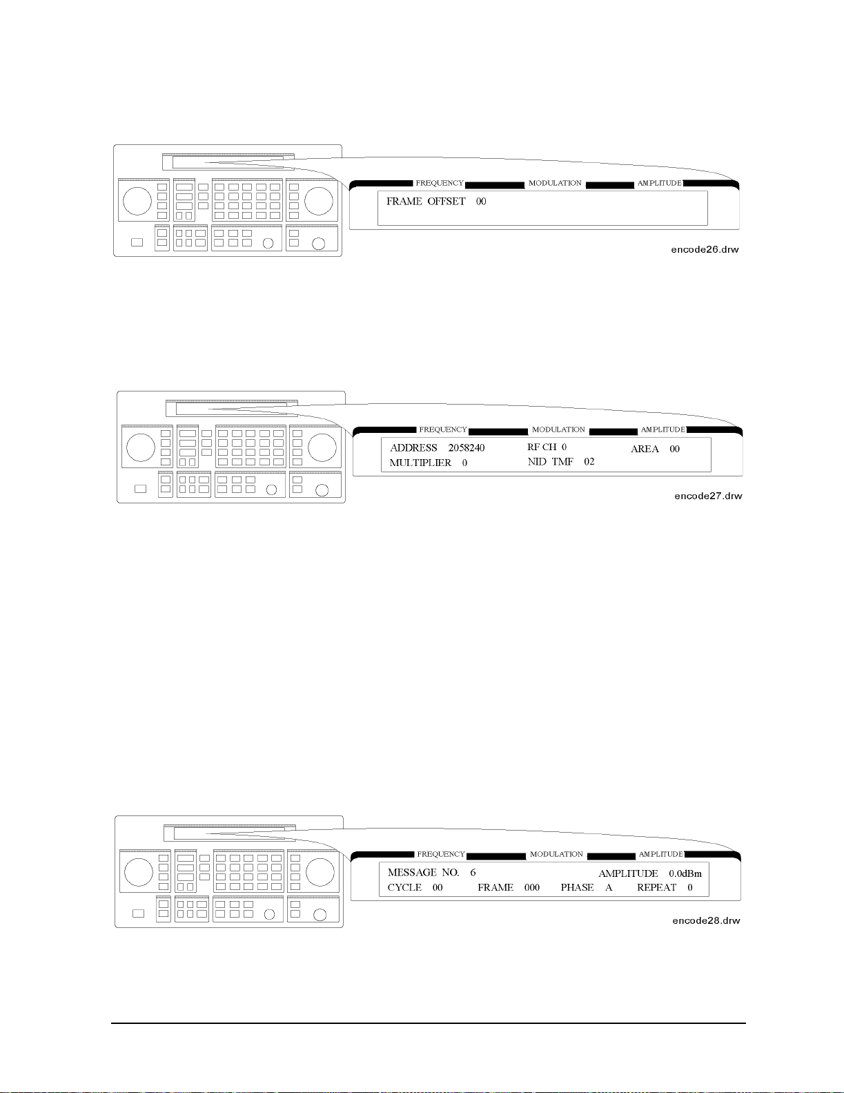
Operation Reference
Function
After completing the previous menu, set FRAM E OFFSET in the following menu:
• FRAME OFFSET: Defines the number of frames to be offset by BIW101 from the signaling frame
at the home area. The allowable range is 0 to 63.
The next menu is displayed for se tt ing the NID mode after completing the SSID mode settings only
if the SSID and NID modes are selected.
• ADDRESS: Defines the network address which appears on the R F channel within the address
field in predicted frames. The allowable range is 2058240 to 2062335.
• RF CH: Represents each RF channel obtained by the formula as follows:
RF CH = Modulo 8 of Integer [(RF Freq. kHz)/(channel space kHz)]
The allowable range is 0 to 7.
• AREA: Defines the service area identification. The allowable range is 0 to 31.
• MULTIPLIER: Defines how much the network address is extended. The allowable range is 0 to 7.
• NID TMF: Defines NID traffic management flag. This value is automatically set when the
capcode (address) is entered in the PAGER CODE data field. The allowable range is 0 to 15.
Message During Encoding To start and stop encoding after selecting all pager encoder
parameters, press the
INCR SET (START/STOP) key. The following display is shown during en coding
a pager under test:
1b-17
Page 66

Operation Reference
Function
NOTE REPEAT is displayed additionally only if FLEX-TD is selected in the format menu.
If MESSAGE NO. is set to 0, the display is changed as follows:
NOTE If the RF output is turned off, AMPLITUDE x.xdBm will be substituted for RF OFF.
While encoding, the blinking cursor is on the first character A of AM PLITUDE or R of RF
OFF.
Signaling Examples The following examples illustrate the frame structure for the three
transmission repetition settings. The HEADER and TERMINATOR parameters are set to ON (default),
and the COLLAPSE CYCLE (CC) is set to 1 and 2 (messages will be repeated every 2 frames (2
2
frames (2
) respectively).
1
) and 4
• SINGLE Mode Example
Start Cycle: 10
Start Frame: 127
Collapse Cycle: Has no effect
—Since HEADER is set to ON, the idle signal is output at Frame 126.
—With TERMINATO R set to ON, the asynchronous state signal is output after the message.
Cycle 10 10 11
Frame 126 127 0
CC = 1 idle message asynchronous
CC = 2 idle message asynchronous
• BURST Mode Example
Start Cycle: 10
Start Frame: 127
Collapse Cycle: 1 (2
1
) and 2 (22)
Burst: 3
—Since HEADER is set to ON, the idle signal is output at Frame 126.
1b-18
Page 67

Operation Reference
Function
—With TERMINATO R set to ON, the asynchronous state signal is output in the fr ame where the
next message was supposed to occur (as determined by the collapse cycle).
Cycle1010 1111 1111 1111 1111 ...11
Frame 126 127 0 1 2 3 4 5 6 7 ... 11
CC = 1 idle message idle message idle message idle asyn-
chronous
CC = 2 idle message idle idle idle message idle idle idle message ... asyn-
chronous
•CONT Mode Example
Start Cycle: 10
Start Frame: 127
Collapse Cycle: 1 (2
1
) and 2 (22)
Stop: Selected in frame f+ 1
—Since HEADER is set to ON, the idle signal is output at Frame 126.
—With TERMINATO R set to ON, and IMMEDIATE STOP set to OFF, selecting stop will replace
the next message with the asynchronous signal.
Cycle1010111111...c cc cc
Frame 126 127 0 1 2 .... f f + 1 f + 2 f + 3 f + 4
CC = 1 idle message idle message idle ... message idle asyn-
CC = 2 idle message idle idle idle ... message idle idle idle asyn-
chronous
chronous
SSID/NID Roaming Example When the roaming function with SSID and NID is set to on with
the following conditions, the contents in each phase are shown in the following table:
• 6400 bps, 4-level FSK
• Call in Phase: A
• Address Type: Long Address
1b-19
Page 68

Operation Reference
Function
• Roaming Mode: SSID, NID
Field Phase A Phase B, C Phase D
Word 0 of
block 0
Word 1 of
block 0
Word 2 of
block 0
Word 3 of
block 0
Word 4 of
block 0
Word 5 of
block 0
Word 6 of
block 0
Word 7 of
block 0
Word 0 of
block 1
Word 1 of
block 1
BI Block Info Dummy Block Info Dummy Block Info
BI BIW000
BI BIW111
BI
BIW101
BIW101
BIW101
a
BIW101
a
a
a
BIW101
BIW101
BIW101
a
a
AF Network Address Idle Idle
AF Address 1 Dummy Address 1‘ Dummy Address 1
AF Address 2 Dummy Address 2 Dummy Address 2
VF Short Message Vector
VF
b
VF
2
(for Network Address)
VF Vector (for Address 1,2) Numeric Vector (for
Dummy Address 1,2)
Numeric Vector (for
Dummy Address 1,2)
VF Message Dummy Message Dummy Message
Word 2 of
MF Message Dummy Message Dummy Message
block 2
:: : : :
: IB Idle Idle Idle
:: : : :
a. BIW101 System Message: Time Instruction,
Seconds Adjust: 0,
Daylight Savings: No (Standard Time),
Local Time zone: Gr eenwich Meridian
b. Vector Type: Short Message/Tone Only,
Message Type: 3 Numeric Characters (000) with Short Address
where,
BI: Block Information
AF: Address Field
VF: V ector Field
MF: Message Field
IB: Idle Block
1b-20
Page 69

Operation Reference
Function
NOTE If the firmware revision of the 8648A option 1EP is B.04.08 or below, the contents in
each phase are shown in the following table:
• 6400 bps, 4-level FSK
• Call in Phase: A
• Address Type: Long Address
• Roaming Mode: SSID, NID
Field Phase A Phase B, C Phase D
Word 0 of
block 0
Word 1 of
block 0
Word 2 of
block 0
Word 3 of
block 0
Word 4 of
block 0
Word 5 of
block 0
Word 6 of
block 0
Word 7 of
block 0
Word 0 of
block 1
Word 1 of
block 1
BI Block Info Dummy Block Info Dummy Block Info
BI BIW000 Idle Idle
BI BIW111 Idle Idle
BI Idle Idle BIW101
AF Network Address Idle Idle
AF Address 1 Dummy Address 1‘ Dummy Address 1
AF Address 2 Dummy Address 2 Dummy Address 2
VF Short Message Vector
(for Network Address)
VF Vector (for Address 1,2) Numeric Vector (for
VF Message Dummy Message Dummy Message
Idle Idle
Numeric Vector (for
Dummy Address 1,2)
Dummy Address 1,2)
Word 2 of
block 2
:: : : :
: IB Idle Idle Idle
:: : : :
MF Message Dummy Message Dummy Message
1b-21
Page 70

Operation Reference
Function
where,
BI: Block Information
AF: Address Field
VF: V ector Field
MF: Message Field
IB: Idle Block
POCSAG
Setting the Data Rate and Pager Type The parameter menu for the data rate and the pager
type looks like the following:
• DATA RATE
512 512 bps
1200 1200 bps
2400 240012 bps
• PAGER TYPE
NUMERIC: Numeric type
TONE ONLY: Tone only type
ALPHANUM 7BIT: 7-bit coded alphanumeric type entered by hex-binary code
ALPHANUM 8BIT: 8-bit coded alphanumeric type entered by hex-binary code
ALPHANUMERIC: 7-bit coded alphanumeric type
NOTE The ALPHANUM 7BIT and ALPHANUM 8BIT types can be used for displaying
two-byte special characters, for example, Chinese ch aracters, through a conversion
table.
The following examples show how the actual bit streams are transmitted if “B0A1” is
set to the message (MESSAGE NO. 6):
1b-22
Page 71
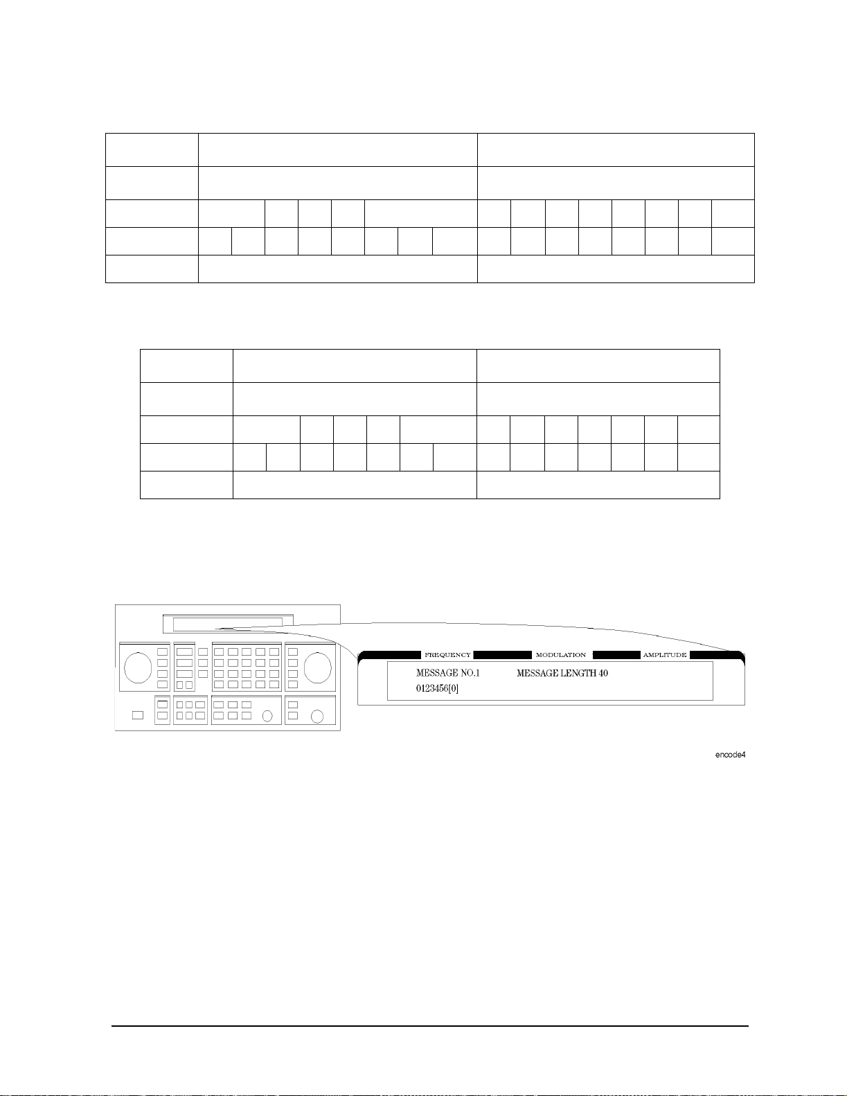
Operation Reference
Function
For ALPHANUM 8BIT
First Byte Second Byte
MSB LSB MSB LSB
Bit numberb8b7b6b5b4b3b2b1 b8b7b6b5b4b3b2b1
Bit streams10110000 10100001
Characters B 0 A 1
For ALPHANUM 7BIT
The eighth bit (b8) is ignored as follows:
First Byte Second Byte
MSB LSB MSB LSB
Bit numberb7b6b5b4b3b2b1 b7b6b5b4b3b2b1
Bit streams0110000 1010001
Characters B (3) 0 A (2) 1
When converting the binary data stream to 2-level FSK, the first bit out becomes the least
significant bit (LSB) of the 2-level symbol with the following bit the most significant bit (MSB) of
the symbol.
Setting the Message The message menu looks like the following:
• MESSAGE NO. is defined as the following where “X” represents the phase setting:
0: Arbitrary message set from the external controller using the GPIB capability.
The data must be entered in units of works. Refer to “[SOURce]:PAGing
[:FORMat]:[POCSag|FLEX|FTS}:ARBitrary:DEFine <NR1>, <NR1>,...,
<NR1>” and “Using the Buffer Memory for the Arbitrary Messages” in Chapter
2.
This arbitrary message buffer is divided into multiple segments by assigning
1b-23
Page 72

Operation Reference
Function
START BATCH and STOP BATCH in the following menu:
The allowable ranges for both are 000 to127.
1: Displays: 0123456[-]
2: Displays: ABCDEFG[P]
3: Displays: TEST PAGING: POCSSAG
4: Displays: ALPHANUMERIC 40CHARS TEST PAGING: POCSAG
5: Displays: 888888888888 88888888 888888 88888888 888888
for LCD test with 40 characters of “8”.
6: User-definable message, up to 40 characters long, set from the front panel. Enter
numeric messages wi th th e key p ad. Alp hanu meri c mes sa ges req ui re t he
rad dBµV
(SHIFT) key to access the alphabetical characters (blue letters) above the keypad.
If required alphabetical characters are not available on the front pane l, send a
message from an external controller over GPIB. Refer to “[SOURce]:PAGing
[:FORMat]:{POCSag|FLEX|FTD}:MESS:DEFine ‘string’” in Chapter 2.
• MESSAGE LENGTH specifies the maximum number of characters that will be sent out and
displayed in the message field. The allowable range is 1 to 40. After specifying the number of
characters, press
MHz dB(m) (ENTER) to save the new value.
When the value of this parameter is equal to or greater than the length of the message, the
whole message will be sent out.
When the value of this parameter is less than the length of the message, only the characters
specified by this parameter are output. (For example, if the MESSAGE NO. is 1 (0123456[-]) and
the MESSAGE LENGTH is 5, the message which is displayed and will be sent out is actually 01234.)
Setting the Encoding Mode The number of times a message is transmitted and the level of that
transmission are determined by the following menu:
1b-24
Page 73

Operation Reference
Function
• MODE determines whether the message will be output once or multiple times when INCR SET
(START/STOP) is pressed.
SINGLE: Outputs the message once.
BURST: Outputs the message the number of times specifi ed in the BURSTS field (3
times in this example).
CONT: Outputs the message continuously until the
INCR SET (START/STOP) key is
pressed a second time.
• AMPLITUDE sets the signal output level of the carrier.
• BURSTS sets the number of times the message will be transmitted. This parameter is displayed
only when the MODE parameter is set to BURST. The allowable range is 1 to 255.
• RF OFF is displayed below the amplitude setting when the RF output is turned off. To toggle the
RF signal output on and off, press
RF ON/OFF.
• HOLD is displayed when the step attenuator is held at its current range setting. To toggle the
attenuator hold function on and off, press
ATTN HOLD.
Entering the Pager Capcode (Address) The pager code menu looks like the following:
• PAGER CODE accepts only numeric characters up to 7 digits.
Use the numeric keys to enter the capcode. Terminate your entry with the
MHz/dB(m) (ENTER)
key.
Message During Encoding To start and stop encoding after selecting all pager encoder
parameters, press the
INCR SET (START/STOP) key. The following display is shown during encoding
a pager under test.
NOTE If the RF output is turned off, AMPLITUDE x.xdBm will be substituted for RF OFF.
While encoding, the blinking cursor is on the first character A of AMPLITUDE or R of
RF OFF.
1b-25
Page 74

Operation Reference
Function
RESYNC
Setting the Encoding Mode The following parameters must be set to activate the
resynchronization function for a FLEX/FLEX-TD pager under test:
• BURSTS defines the number of data to make a pager resynchronized with this pager encoding
signal. One burst is 1.92s. The allowable range is 000 to 256. 0 represents the continuous mode.
NOTE This setting is required only when RESYNC is selected in the format menu. The ⇑
(PREV) and ⇓ (NEXT) keys toggle the format menu and this BURSTS menu. No other
menus are displayed.
Message During Resynchronizing To start and stop encoding after selecting all pager encoder
parameters, press the
INCR SET (START/STOP) key.
NOTE If the RF output is turned off, AMPLITUDE x.xdBm will be substituted for RF OFF.
While encoding, the blinking cursor is on the first character A of AMPLITUDE or R of
RF OFF.
PN15
Setting the Data Rage If PN15 modulation is selected in the format menu, the following
parameters must be set to complete the pager encoder setup process.
1b-26
Page 75

Operation Reference
Function
• DATA RATE
512/2: 512 bps, 2-level FSK
1200/2: 1200 bps, 2-level FSK
1600/2: 1600 bps, 2-level FSK
2400/2: 2400 bps, 2-level FSK
3200/2: 3200 bps, 2-level FSK
3200/4: 3200 bps, 4-level FSK
6400/4: 6400 bps, 4-level FSK
NOTE This setting is required only when PN15 is selected in the format menu. The ⇑ (PREV)
and ⇓ (NEXT) keys toggle the format menu and this PN15 FSK data rate menu. No
other menus are displayed.
Message During Encoding To start and stop encoding, press the
INCR SET (START/STOP) key.
NOTE If the RF output is turned off, AMPLITUDE x.xdBm will be substituted for RF OFF.
While encoding, the blinking cursor is on the first character A of AMPLITUDE or R of
RF OFF.
SERVICE This function is used for servicing the 8648a Option 1EP, and provides a
continuous FSK signal.
Setting the Data Rate The following parameter must be set to activate the service function:
1b-27
Page 76

Operation Reference
Function
• CALIBRATION FSK is one of the data rates as follows:
512/2: 512 bps, 2-level FSK
1200/2: 1200 bps, 2-level FSK
1600/2: 1600 bps, 2-level FSK
2400/2: 2400 bps, 2-level FSK
3200/2: 3200 bps, 2-level FSK
3200/4: 3200 bps, 4-level FSK
6400/4: 6400 bps, 4-level FSK
NOTE This setting is required only when SERVICE is selected in the format menu. The ⇑
(PREV) and ⇓ (NEXT) keys toggle the blinking cursor between the format parameter
and this CALIBRATION FSK parameter. No other menus are displayed.
Message During Servicing To start and stop encoding, press the
INCR SET (START/STOP) key.
NOTE If the RF output is turned off, AMPLITUDE x.xdBm will be substituted for RF OFF.
While encoding, the blinking cursor is on the first character A of AMPLITUDE or R of
RF OFF.
1b-28
Page 77

Operation Reference
Pulse Modulation
NOTE Pulse modulation is valid only for instruments with Option 1E6.
Function
1. PULSE
To select pulse modulation, press
the following representation. The
AM (PULSE) twice. If RF is on, the display will look like
MOD ON/OFF key enables or disables the pulse
modulator.
When the instrument is in the pulse modulation mode , puls e modulati on should be tur ned
off using
MOD ON/OFF before switching off the instrument. If the ins trument is switched of f
while the pulse modulation mode is turned on, the instrument will power up with no RF
output.
NOTE The word PULSE is shown in the AMPLITUDE portion of the display when
pulse modulation is enabled (
(
RF ON/OFF). In this case, no RF will be present at the RF output unless a
MOD ON/OFF) and the RF is turned on
TTL-high signal is applied to the rear-panel PULSE IN connector.
1b-29
Page 78

Operation Reference
Function
The following keys are invalid when the pulse modulation screen is visible:
INT 400 Hz
•
• INT 1kHz
• EXT AC
• EXT DC
• 1kHz+EXT DC
1b-30
Page 79

Increment Set
1. INCR SET
Operation Reference
Function
Press
(the active function is the last func tion key you press;
ΦM). When you press INCR SET, ⇑ is displayed between the value and the units. The ⇓
INCR SET to view or change the increment set value for the currently active function
FREQUENCY, AMPLITUDE, FM, AM, or
indicates that the displayed value is the increment set value.
NOTE An increment value cannot be set for the knobs or the memory recall arrow
keys.
Increment Set Ranges
Function Range
Frequency 1 Hz to 999.75 MHz
Amplitude > 0.0 to 149.0 dB (8648A)
Amplitude > 0.0 to 150.5 dB (8648B/C/D)
FM Deviation > 0.0 to 100 kHz
AM Depth > 0.0 to 100%
ΦM Deviation > 0.0 to 10.0 Radians
Internal Audio Generator
(Options 1EP and 1E2 only)
0.01 to 1.0 kHz
NOTE It is possible to set an increment value of greater resolution than can be
displayed or than the hardware can respond to. However, the instrument
records each arrow key press and will respond after the appropriate number
of presses.
START/STOP Encoding If Option 1EP is present a n d th e si g n a l gen e ra tor is in the
ENCODER mode, the
INCR SET key functions as a START/STOP key to start or stop the
pager encoding when in the pager encoder mode .
PREV and NEXT If Option 1EP is present and the signal generator is in the ENCODER
mode, the ⇑ and ⇓ keys function as the PREV and NEXT keys to change the blinking first
character between each parameter when in the pager encoder mode.
1b-31
Page 80

Operation Reference
Function
Data
1. MHz/dBm, kHz/mV, %/µV, rad/dBµV
Press a units key after you enter a value. This terminates the entry.
Note that the units keys in the left column are each labeled with an amplitude unit on the
bottom and a frequency or modulation unit on the top . The inst rument applies the
appropriate unit for the function value you are entering. The bottom key in the row for
instance, terminates a ΦM entry in radians or an amplitude entry in dBµV.
NOTE Memory register selections, seq uence selections, and HP-IB address entrie s
do not require a units key to terminate the entry. These entries are
automatically terminated after the last digit is entered.
Units Conversion You can change the units of the displayed frequency or amplitude
value by selecting the FUNCTION (frequen cy or amplit ude) and th en pressing a units key.
The instrum e n t w i ll co n v e r t th e di splayed value to th e eq u i v a l e n t value for the un i ts key
you pressed.
ENTER If Option 1EP is present and the signal generator is in the ENCODER mode, the
MHz dB(m) key functions as an ENTER key. The ENTER key must be used to store any
numeric or alphabetic characters entered by way of the DATA and MODULATION source
blocks.
SHIFT If Option 1EP is present and the signal generator is in the ENCODER mode, the
rad dBµV key functions as a SHIFT key. This key lets you input alphabetical characters
using the DATA and MODULATION SOURCE blocks when in the pager encoder mode.
2. Backspace
Press ⇐ when entering a numeric value to backspace and remove the last digit entered.
1b-32
Page 81

Operation Reference
Function
3. emf
Press these keys to display the amplit ude value indicated on the key label in electromotive
force units. Emf is th e RF out put volt age with no l oad. It is twice the out put volta ge with a
50 ohm load.
4. ±
Press this key at any time while you are entering an amplitude or ref erence of fset value to
change the sign of the value.
1b-33
Page 82

Operation Reference
Function
Instrument Preset
POWER ⇐
Turn the instrument on while pressing the backspa ce ke y (⇐)to perform an instrument
preset. The instrument will power up to factory-defined settings shown in the following
table. Save and recall registers are not affected by this operation.
POWER DEL
Turn the instrument on while pressing the memory DEL key to perform a clear memory.
This function erases all save/recall re gisters , sets the GPIB address to 19, and perfo rms an
instrument preset where the instrument powers up to factory-defined settings shown in
the following table.
NOTE This will cause an error message to appear o n the displ a y: 627 Battery RAM
failure: memory lost. This is normal.
1b-34
Page 83

Operation Reference
Instrument Preset Settings
Function Parameter Setting
RF Frequency Frequency 100 MHz
Increment 10 MHz
Reference 0.0 MHz
RF Amplitude Power Level −136 dBm
Increment 1.0 dBm
Reference 0.0 dBm
FM Input Internal
Frequency 1 kHz
Coupling AC
State Off
Function
Deviation 30%
Increment 0.1 kHz
AM Input Internal
Frequency 1 kHz
State Off
Depth 30%
Increment 0.1%
ΦMInputInternal
Frequency 1 kHz
Coupling AC
State Off
Deviation 1.0 radians
Increment 0.1 radians
RF State Off
Attenuator Coupling Off
Pulse (Option 1E6) State Off
1b-35
Page 84

Operation Reference
Function
Pager Encoding (Option 1EP) FORMAT FLEX
Instrument Preset Settings
Function Parameter Setting
POLARITY NORMAL
FILTER ON
DATA RATE 1600/2 (for FLEX/FLEX-TD)
512 (for POCSAG)
PAGER TYPE NUMERIC
VECTOR TYPE STANDARD
BLOCKING LENGTH 1BIT
FUNCTION 00
MESSAGE NO. 1
MESSAGE LENGTH 40
MODE SINGLE
BURSTS 1
IMMEDIATE STOP OFF
HEADER ON
TERMINATOR ON
PAGER CODE A0000001 (for FLEX/FLEX-TD)
0000000 (for POCSAG)
ADDRESS TYPE SHORT
ADDRESS1 0032769
ADDRESS2 0000000
CYCLE 0
FRAME 0
PHASE A
COLLAPSE CYCLE 4
REPEAT 0
INTERNAL AUDIO
GENERATOR
1
START FRAME/BATCH 0
STOP FRAME/BATCH 127
DUMMY CALL OFF
ADDRESS1 (DUMMY CALL) 0032769
ADDRESS2 (DUMMY CALL) 0000000
1b-36
Page 85

Instrument Preset Settings
Function Parameter Setting
Operation Reference
Function
Modulation
Generator
(Option 1E2)
FREQUENCY 1.00 kHz
SHAPE SINE
1b-37
Page 86

Operation Reference
Function
GPIB
1. ADRS
Press
ADRS to view the instrument’s GPIB add r ess setting in the s e co n d l i n e o f th e
FREQUENCY display.
To change the address, press
ADRS and a two-digit number. For example, enter 01 to set
the address to 1.
Acceptable HP-IB addresses are 00 through 30.
2. LOCAL
Press
LOCAL to return to front-panel operation when the instrument has been set for
remote operation. The SEQ and REG fields will replace the HP-IB status indications in the
second line of the FREQUENCY display when the instrument is returned to local
operation.
1b-38
Page 87
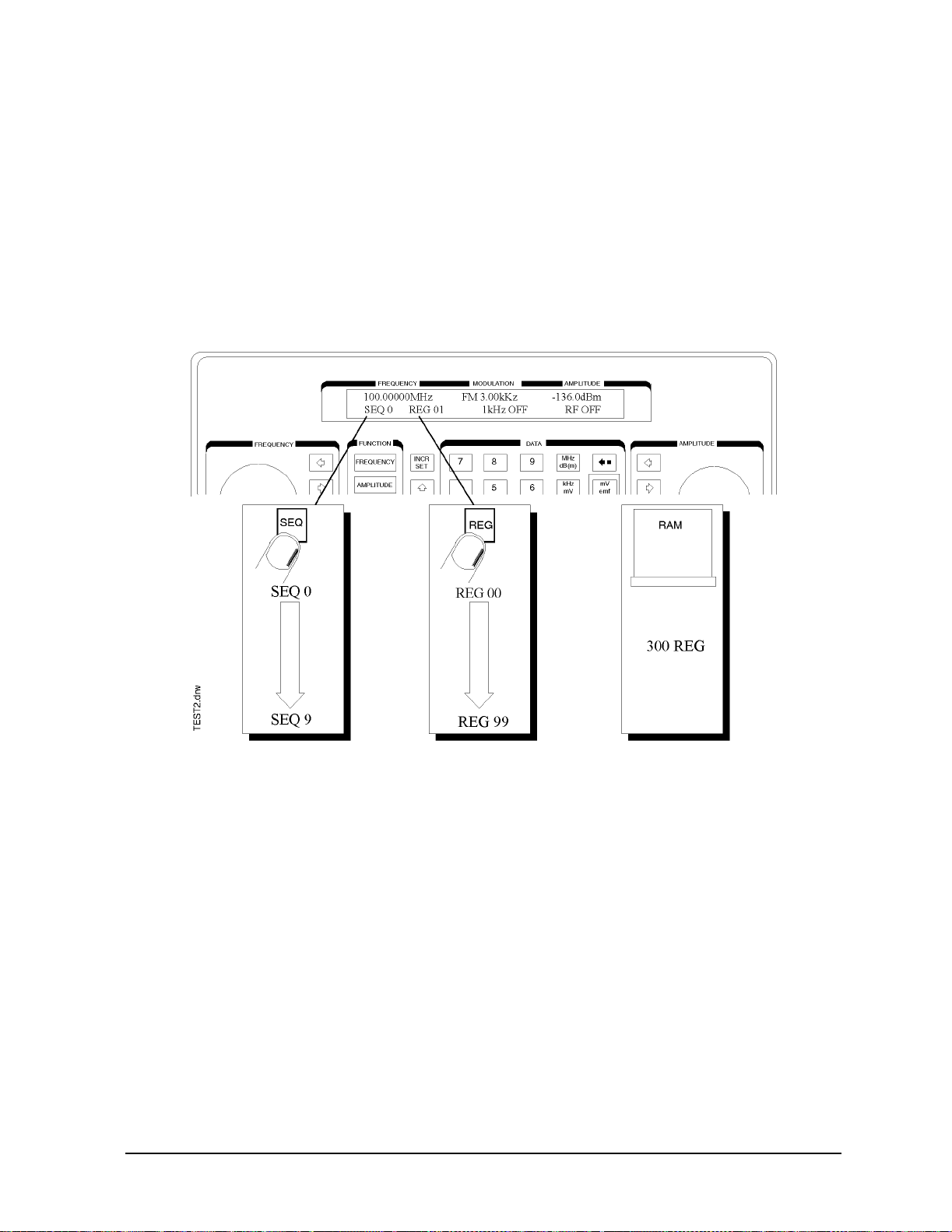
Operation Reference
Function
Memory
The memory keys allow you to save instrument settings into memory registers and recall
the registers in a numeric sequence.
Up to 10 register sequence s can be def ined (0 through 9) . A s equence can cont ain up t o 10 0
registers (00 through 99). There are a total of 300 registers available in the instrument.
The registers can be used in the sequences in any combinatio n (such as 10 sequences of 3 0
registers each, or 3 sequences of 100 registers each) as long as the total does not exceed
300 registers. It is not possible to have all 10 sequences each contain 100 registers as that
would be 1000 registers. (If Option 1EP is present, there are a total of 70 registers
available.)
Memory key entries are automatically terminated after you enter the last digit. Register
key entries (
SAV, DEL, and REG), require two digits. Sequence key entries (SEQ) require
one digit.
1b-39
Page 88

Operation Reference
Function
1. SAV
Press
SAV and a register number (00 through 99) to save the current operating settings in
a memory register. All front-panel settings except the knob digit positions and the GPIB
address will be saved in the register .
When you press the
SAV key, a message is displayed to tell you the total number of
registers still available.
When you save a register, it is assigned to the currently selected s equence . ( The number o f
the selected sequence appears in the second line of the FREQUENCY display.) You can
only recall a register when the sequence it is assigned to is selected.
(Refer to "4. SEQ" for further information about re gi ster sequences.)
NOTE The instrument does not have a copy function for saving registers from one
sequence to another.
2. REG
Press
REG and a register number (00 through 99) to recall the operating settings saved in
that register.
The number of the last register recalled appears in the display along with the number of
the currently selected sequence.
You can only recall registers from the currently selected sequence.
To recall a register from another sequence, you must first select the sequence using the
SEQ key.
If you recall a register remotely in 8656/57-compatible language and nothing has been
saved in that register, the instrument preset settings will be restored.
1b-40
Page 89

Operation Reference
Function
3. Register Recall Arrows
The recall ⇑ and ⇓ keys can be used to select sequences or recall re gisters. The last key
pressed (
SEQ or REG) determines which field is affected by the arrow keys.
(Refer to "4. SEQ" for further information about re gister sequences.)
4. SEQ
Press
SEQ and a sequence number (0 through 9) to select a register sequence. When you
select a sequence, the number of the sequence appears in the display along with the
number of the first register saved in the sequence. The instrument is set to the operating
settings saved in the first register. If no registers have been saved in the sequence, a
message is displayed to let you know.
NOTE Selecting th e seq uence you ar e currently i n is a qu i ck way to re turn to the
beginning of the sequence
A sequence can include up to 100 registers (00 through 99). There are a total of 300
registers available in the standard instrument and 70 registers in and instrument with
Option 1EP (pager encoder) installed. Registers are automatically assigned to the
currently selected sequence when they are save d. The registers saved in any given
sequence are independent from the registers in any other sequenc e. This allows you to
create up to ten different register sequences. Consequently, it is possible to have up to ten
registers with the same number (for exampl e, REG 01) each assigned to a different
sequence and each with different operating settings saved in it.
1b-41
Page 90

Operation Reference
Function
5. DEL
Press
DEL and a register number (00 through 99) to delete that register. The specified
register is deleted from the currently selected sequence only, but registers in other
sequences you have set up are not affected. After yo u have deleted a register, you will not
be able to recall that register number until you have saved ope rating settings in it again.
NOTE The register number is immediately deleted from the seque nce when the
delete entry is completed. However, the settings contained in the register are
recalled when you delete the register so you can re-save the settings if you
need to.
Renumbering the Register s If you use the arrow keys to recall the registers in
sequence, the deleted regis ter number will be skipped. If you wish to eliminate the skip,
you can do so by moving each register following the deleted register back one register
number. To delete an entire sequence, delete each register in the sequence.
1b-42
Page 91

Modulation Source
Figure 1-2. Modulation Source P aths (the 1 kHz path is highlighted)
Operation Reference
Function
1b-43
Page 92

Operation Reference
Function
1. MOD ON/OFF
Press
MOD ON/OFF to turn on or off the currently-selected modulation mode (AM, FM, ΦM,
or pulse). OFF appears in the second l ine of the MODULATION d isplay when modulation is
turned off.
This key also turns on or off the audio output at the MOD INPUT/OUTPUT connector
when an internal source (400 Hz or 1 kHz) is selected.
The operation of this key is the same as the
MOD ON/OFF key on the 83300A Remote
Interface.
2. INT 400 Hz, INT 1 kHz
Press one of these keys to s elect an interna l source for modulat ing the carr ier. The selected
source is also output at the MOD INPUT/OUTPUT port as a 1 Vpk signal into 600 ohms.
3. (FREQUENCY), 4. (FREQUENCY/WAVEFORM)
If Option 1EP is present, the
INT 1kHz (FREQUENCY/WAVEFORM) key will toggle between the 1 kHz internal source
INT 1kHz (FREQUENCY) key, or if Option 1E2 is present, the
and the internal variable-frequency generator with its four waveforms. Repetit i vely
pressing the
INT 1kHz key toggles between 1kHz (the 1 kHz internal source), SI N (the sine
waveform), TRI (the triangle waveform), SQU (the square wavefo rm), and SAW (the saw or
ramp waveform).
The frequency of the modulated frequency may be changed by entering the frequency on
the keypad and terminating the value with t he
is accepted. Therefore , to set a frequency of 10 Hz, you must press
knob will not change this frequency. After the frequency is set, toggling the
kHz key. kHz is the only valid units key that
.01 kHz. The frequency
INT 1kHz key
only changes the waveform. The frequency remains unchanged.
1b-44
Page 93

Operation Reference
Function
The acceptable frequency range for the internal variable-frequency generator is 10 Hz to
20 kHz.
Pressing
AM, FM, or ΦM allows you to store a variable frequency and waveform for each of
these types of modulation. After setting up one of thes e types of modulation with a
frequency/waveform combination, simply pressing that modulation key (
AM, FM, or ΦM)
recalls the frequency/waveform combination that was set up earlier. For example, an
instrument is configured so the AM state is set up with a 2 kHz sine waveform, the FM
state is set up with a 500 Hz square waveform, and the ΦM state is set up with a 5 kHz
triangle wavef o rm. Then pres s in g either
AM, FM, or ΦM will set the instrument to that
modulation type with the frequency/waveform combination to which it was previously set.
NOTE If another key (for example, FREQUENCY, AMPLITUDE, and so forth) is pressed
after a frequency and waveform combination is set, pressing the
once makes the
INT 1kHz active. Subsequent key presses toggles the
INT 1kHz key
instrument through its waveform choices.
5. EXT AC, EXT DC
Press one of these keys to configure the MOD INPUT/OUTPUT port as an ac- or
dc-coupled input for modulating the carrier.
Calibrated modulation requires an audio source of 1 Vpk into 600 ohms. For audio source
frequencies of less than 10 kHz, a HI or LO indicator will appear in the second line of the
MODULATION display when the level of the source is not within approximately ±5% of
1Vpk.
Acceptable Frequency Ranges for an
External Audio Source
Modulation Coupling Range
FM EXT AC 1 Hz to 150 kHz
EXT CC DC to 150 kHz
ΦM EXT AC 20 Hz to 10 kHz
If you press
a
AM
a
AM
a. AM bandwidth degrades at carrier
frequencies below 1.5 MHz and is not
specified.
EXT DC while the instrument is already in external dc mode and the FM is on,
EXT AC 1 Hz to 25 kHz
EXT AC DC to 25 kHz
then the instrument will perform a dc FM calib ration. The calibrati on takes approx imately
one second. During the calibration the following message appears on the display: DCFM
calibration in progress.
1b-45
Page 94

Operation Reference
A
1
-
3 kHz
1
-
z
Function
6. 1 kHz + EXT DC
1 kHz + EXT DC to configure the MOD INPUT/OUTPUT port as a dc-c oupled input for
Press
modulating the carrier along with the internal 1 kHz source.
(Refer also to "3. EXT AC EXT DC" for further information about operation and accep table
ranges.)
NOTE 1 kHz + EXT AC, 400 Hz + EXT DC, and 400 Hz + EXT AC are available only
via GPIB.
Setting the Modulation Level When modulating with both an internal and external
source, the level of the external source should not exceed 0.5 V peak or 0.5 Vdc. This level
will provide one half of the displayed modulation. To set modulation to the level you desire,
set the displayed modulation to two-thirds of the desired setting. The external source, set
to 0.5 V peak or 0.5 Vdc, will provide the additional one-third of the desired setting
(one-half of the instrument’s setting).
For example, to set up the modulation for 3 kHz of FM deviation, set the instrument for 2
kHz of FM. The external source, set to 0.5 V peak, will provide another 1 kHz of deviation.
If the external source is set to less than 0.5 V peak, the modulation level provided by the
external source will be less than one-half of the displayed modulation. The following
equation may be helpful for determining the appropria te modulation level setting for the
instrument when the level of the external source is less than 0.5 V.
----------- -D=
E+
Where:
• A = Actual modulation level
• E = External source level
• D = Displayed modulation level
For example, to set up for 3 kHz of FM deviation with an external source set
to 0.3 V peak, the instrument’s displa yed modulation level would be:
--------------------- 2.3 kH
0.3 V+
7. MOD INPUT/OUTPUT
This port outputs a 1 Vpk (into 600 ohms) audio tone when an internal modulation source
is selected. When an external modulation input is selected (
), it provides the input for a 1 Vpk (into 600 ohms) aud io source. (Refer to the preceding
DC
table for acceptable frequency ranges.)
=
EXT AC, EXT DC or 1kHz+EXT
1b-46
Page 95

RF Output
1. RF ON/OFF
Operation Reference
Function
Press
RF ON/OFF to turn the RF output signal on or off. RF OF F appears in the second line
of the AMPLITUDE display when the output signal is off.
The instrument turns off the output signal by switching in the maximum output
attenuation (130 dB) and setti ng the vernier to its lowest setting. This results in
approximately 170 dB of carrier isolation.
2. ATTN HOLD
Press
ATTN HOLD to hold the step attenuator at its current sett ing. HOLD appears in the
second line of the AMPLITUDE display when the attenuator hold function is on.
When the attenuator hold function is on, amplitude adjustments are limited to the range
of the instrument’s vernier. The vernier provides 0.1 dB per step adjustment resolution
across its specified 10 dB range.
1b-47
Page 96

Operation Reference
Function
Vernier Ranges The following table, "10 dB Specif ied Vernier Ranges", provides the
upper and lower limits of each vernier range. The instrument’s amplitude setting when
you press the
ATTN HOLD key determines which vernier range is used.
The vernier is allowed to over - range an d under-range beyond the li mits shown in t he table
ATTN HOLD is selected. However, amplitude settings that exceed the limits may not
when
provide output levels that are within the accuracy specifications of the instrument.
10 dB Specified Vernier Ranges
Range Upper and Lower Limits
1
2 −6.0 dBm to −15.9 dBm
3 −16.0 dBm to −25.9 dBm
4 −26.0 dBm to −35.9 dBm
5 −36.0 dBm to −45.9 dBm
6 −46.0 dBm to −55.9 dBm
7 −56.0 dBm to −65.9 dBm
8 −66.0 dBm to −75.9 dBm
9 −76.0 dBm to −85.9 dBm
10 −86.0 dBm to −95.9 dBm
11 −96.0 dBm to −105.9 dBm
12 −106.0 dBm to −115.9 dBm
13 −116.0 dBm to −127.0 dBm
14 −127.1 dBm to −136.0 dBm
a. +13 dBm for 8648B/C/D
+10.0 dBm
a
to −5.9 dBm
3. RF OUTPUT
The following table shows the reverse power protection for the RF output port of each
instrument model. When the instrument senses a reverse-power signal, it turns the RF
output off, the step attenuator to maximum attenuation, and the vernier to its lowest
setting. A message appears in the second line of the display when the reverse power
protection has been activated.
After you have removed the reverse-power signal from the RF output, press the
RF ON/OFF
key to turn the output signal on again.
1b-48
Page 97
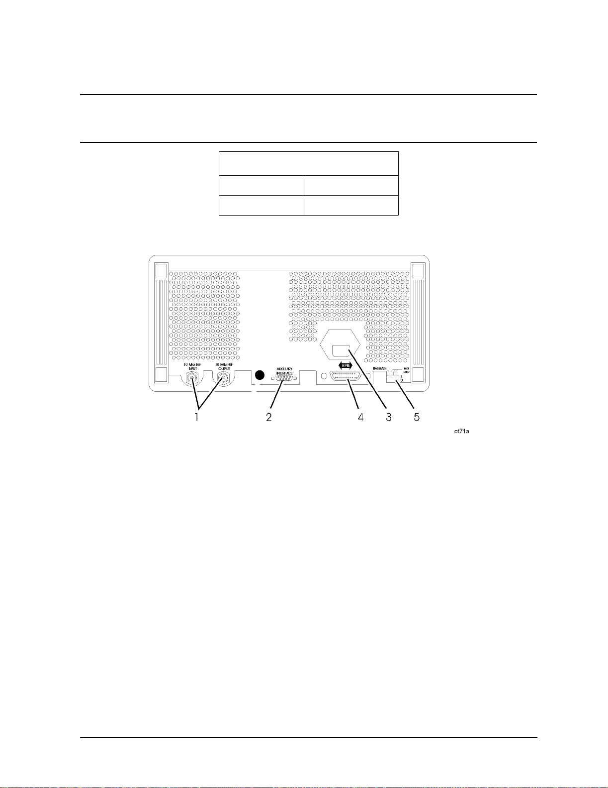
Operation Reference
Function
CAUTION Applying a signal source to the RF output port that exceeds the power level
listed or maintaining a signal source at t he RF output for an extended period
of time may damage the instrument.
Reverse Power Protection
≤ 2000 MHz 50 watts into 50Ω
> 2000 MHz 25 watts into 50Ω
Rear Panel
1. 10 MHz REF INPUT and OUTPUT
These connectors provide the input and output ports for the instrument’s timebase
reference. The instrument will l ock to a 2 MHz, 5 MHz, or 10 MHz external reference
source connected to the input that is within ±5 ppm. When the internal timebase is being
used, the output connector provides a 10 MHz, 1 Vrms level signal.
2. DISPLAY CONTRAST
This knob controls the front panel display contrast. Display contrast can be optimized for
viewing the display from above, below, or directly in front of it.
3. AUXILIARY INTERFACE
Connect the 83300A Remote Interface or the 83301A Memory Interface to this conne ctor
for operation with the instrument. Refer to "Remote Inter face" and "Memory Interface" in
1b-49
Page 98
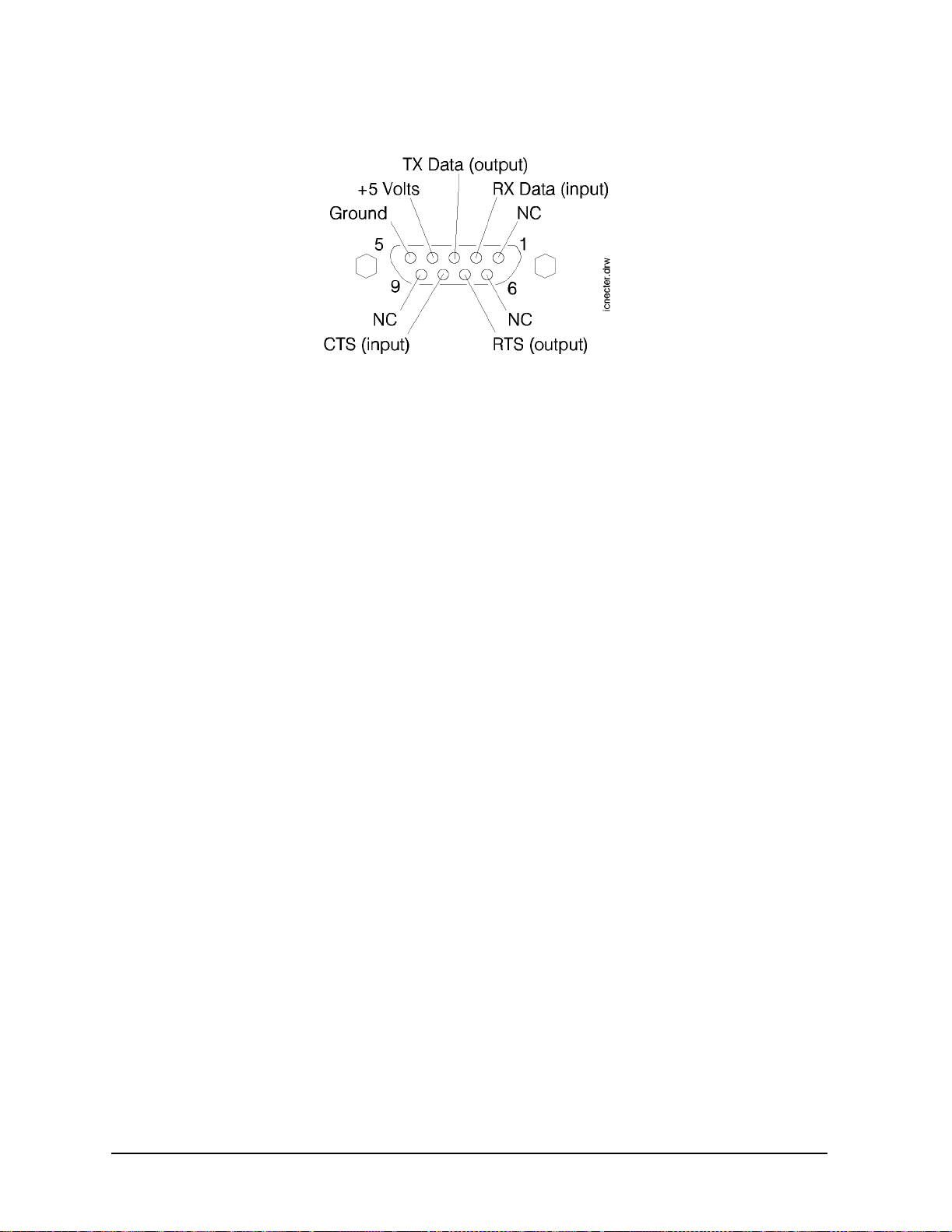
Operation Reference
Function
this section for information about operating these devices.
4. Line Voltage Connector
For information about the line voltage connector or fuse replacement, refer to Chapter 3,
"Installation."
5. HP-IB Connector
This is an IEEE 488.1-1987 connector for controlling the instrument via an external
controller. For information about GPIB operation of the ins trument, refer to Chapter 2,
"GPIB Programming."
6. TIMEBASE ADJ and Language Switches
Position o ne of this switch p laces the instrument in the timebase adjustment mode . For the
timebase adjustment procedure, refer to Chapter 7, "Adjustments."
Position two of this switch allows you to set the language for remo te programming to
either 8656/57-compatible language (1) or to SCPI (0). The language switch is read once at
power-up.
7. External Pulse In p ut
This connector provides the input for an external TTL signal which is used by the pulse
modulator to modulate the RF signal off and on. This connector is on Option 1E6 only.
1b-50
Page 99
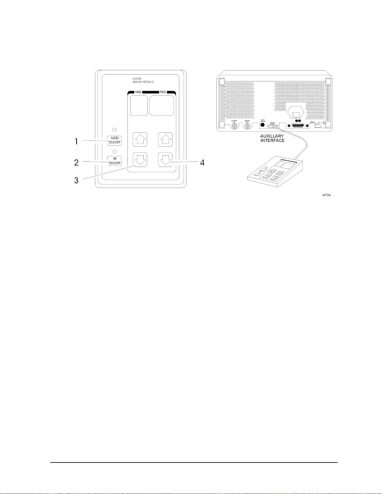
Remote Interface (Accessory)
Operation Reference
Function
1. MOD ON/OFF
Press
MOD ON/OFF to turn on or off all modulation (internal and external) to the RF
carrier. When modulation is turned off, the LED above the key is off and OF F appears in
the second line of the instrument’s MODULATION display.
This key also turns on or off the audio output at the MOD INPUT/OUTPUT port when an
internal source (400 Hz or INT 1 kHz) is selected.
2. RF ON/OFF
Press
RF ON/OFF to turn the RF output signal on or off. When the RF output signal is
turned off, the LED above the key is off and RF OFF appears in the second line of the
instrument’s AMPLITUDE display. There is approximately 170 dB of carrier isolation
when the output is off.
3. Sequence Selection Arrows
Press ⇑ or ⇓ to select the next or p revious sequence of register s . The se quences are selec ted
in numeric order. The number of the selected sequence appears in the second line of the
FREQUENCY display. When a sequence is selected, the first register in the sequence is
recalled. When a sequence is selected that has no registers saved in it, two dashes (- -) will
appear in the REG field.
1b-51
Page 100

Operation Reference
Function
4. Register Recall Arrows
Press ⇑ or ⇓ to recall the operating settings saved in the regi sters in the curr ently select ed
sequence. The number of the last registe r accessed appears in the REG field.
If two dashes (- -) appear in the REG field, a sequence that has no registers saved in it has
been selected.
After the last register in the sequence has been recalled, the register count will begin
again at the first register saved in the sequence.
(Refer to “MEMORY” in this section for further informat ion about register sequences.)
1b-52
 Loading...