

Page 1

Agilent 86100B Wide-Bandwidth Oscilloscope Getting Started
Page 2

Notices
© Agilent Technologies, Inc. 2000-2002
No part of this manual may be reproduced in any form or by any means
(including electronic storage and
retrieval or translation into a foreign language) without prior agreement and written consent from Agilent Technologies,
Inc. as governed by United States and
international copyright lays.
Manual Part Number
86100-90054
Edition
First edition, October 2002
Printed in USA
Agilent Technologies, Inc.
Lightwave Division
3910 Brickway Boulevard
Santa Rosa, CA 95403, USA
Warranty
The material contained in this document
is provided “as is,” and is subject to being
changed, without notice, in future editions. Further, to the maximum extent
permitted by applicable law, Agilent disclaims all warranties, either express or
implied, with regard to this manual and
any information contained herein, including but not limited to the implied warranties of merchantability and fitness for a
particular purpose. Agilent shall not be
liable for errors or for incidental or consequential damages in connection with the
furnishing, use, or performance of this
document or of any information contained herein. Should Agilent and the
user have a separate written agreement
with warranty terms covering the material in this document that conflict with
these terms, the warranty terms in the
separate agreement shall control.
Technology Licenses
The hardware and/or software described
in this document are furnished under a
license and may be used or copied only in
accordance with the terms of such
license.
Safety Notices
CAUTION
Caution denotes a hazard. It calls attention
to a procedure which, if not correctly performed or adhered to, could result in
damage to or destruction of the product.
Do not proceed beyond a caution sign
until the indicated conditions are fully
understood and met.
WARNING
Warning denotes a hazard. It calls attention
to a procedure which, if not correctly performed or adhered to, could result in
injury or loss of life. Do not proceed
beyond a warning sign until the indicated
conditions are fully understood and met.
Restricted Rights Legend
If software is for use in the performance
of a U.S. Government prime contract or
subcontract, Software is delivered and
licensed as “Commercial computer software” as defined in DFAR 252.227-7014
(June 1995), or as a “commercial item” as
defined in FAR 2.101(a) or as “Restricted
computer software” as defined in FAR
52.227-19 (June 1987) or any equivalent
agency regulation or contract clause. Use,
duplication or disclosure of Software is
subject to Agilent Technologies’ standard
commercial license terms, and non-DOD
Departments and Agencies of the U.S.
Government will receive no greater than
Restricted Rights as defined in FAR
52.227-19(c)(1-2) (June 1987). U.S. Government users will receive no greater
than Limited Rights as defined in FAR
52.227-14 (June 1987) or DFAR 252.2277015 (b)(2) (November 1995), as applicable in any technical data.
ii
Page 3

Contents
1 Setting Up the Infiniium DCA
Step 1. Inspect the Shipment 1–5
Step 2. Install any Modules 1–9
Step 3. Consider Environmental Specifications 1–10
Step 4. Connect the Keyboard and Mouse (Optional) 1–11
Step 5. Connect the Line Cord 1–12
Step 6. Turn on the line power 1–15
Step 7. Set the time and date 1–17
Step 8. Connect a Printer 1–18
Step 9. Calibrate the Touch Screen 1–22
Step 10. Configure the Instrument on a LAN 1–23
Step 11. Avoid Costly Repairs 1–24
Step 12. Perform a Module Calibration 1–26
Step 13. For More Information 1–29
Cleaning Connections for Accurate Measurements 1–30
Returning the Instrument for Service 1–39
Hard Drive Recovery 1–42
Agilent Technologies Service Offices 1–43
2 Working in Comfort
3 Using the Infiniium DCA
Eye/Mask Mode 3–7
Oscilloscope Mode 3–8
TDR/TDT Mode 3–9
Using Plug-in Modules 3–10
Using the Touch Screen 3–12
Using the Quick Measure Feature 3–13
If the Display Goes Blank 3–14
Hiding and Moving Dialog Boxes 3–15
Menus 3–16
4 Using the Built-In Information System
The Infiniium DCA Help Contents 4–3
Description of the Contents Topics 4–4
Getting Help While Changing Instrument Settings 4–6
Learning About Measurements Results 4–7
Contents-1
Page 4

Contents
Hiding the Help 4–8
Printing the Contents of a Topic 4–9
Selecting the Help Language 4–10
5 Regulatory Information
Compliance with German Noise Requirements 5–2
Compliance with Canadian EMC Requirements 5–2
Declaration of Conformity - Mainframe 5–3
Declaration of Conformity - Plug-in Modules 5–4
Contents-2
Page 5

1
Step 1. Inspect the Shipment 1-5
Step 2. Install any Modules 1-9
Step 3. Consider Environmental Specifications 1-10
Step 4. Connect the Keyboard and Mouse (Optional) 1-11
Step 5. Connect the Line Cord 1-12
Step 6. Turn on the line power 1-15
Step 7. Set the time and date 1-17
Step 8. Connect a Printer 1-18
Step 9. Calibrate the Touch Screen 1-22
Step 10. Configure the Instrument on a LAN 1-23
Step 11. Avoid Costly Repairs 1-24
Step 12. Perform a Module Calibration 1-26
Step 13. For More Information 1-29
Cleaning Connections for Accurate Measurements 1-30
Returning the Instrument for Service 1-39
Hard Drive Recovery 1-42
Agilent Technologies Service Offices 1-43
Setting Up the Infiniium DCA
Page 6

Setting Up the Infiniium DCA
Setting Up the Infiniium DCA
Setting Up the Infiniium DCA
This chapter shows you how to properly set up your Infiniium DCA. Follow the
setup steps in the order presented. In addition, you will learn how to use
proper optical connection cleaning techniques to avoid costly repairs. Lastly,
this chapter explains how to return your instrument for service.
General Safety Considerations
This product has been designed and tested in accordance with the standards
listed in the Manufacturer’s Declaration of Conformity, and has been supplied
in a safe condition. The documentation contains information and warnings
which must be followed by the user to ensure safe operation and to maintain
the product in a safe condition.
Install the instrument according to the enclosure protection provided. This
instrument does not protect against the ingress of water. This instrument protects against finger access to hazardous parts within the enclosure.
1-2
Page 7

Setting Up the Infiniium DCA
General Safety Considerations
WARNING If this product is not used as specified, the protection provided by the
equipment could be impaired. This product must be used in a normal
condition (in which all means for protection are intact) only.
WARNING No operator serviceable parts inside. Refer servicing to qualified
service personnel. To prevent electrical shock do not remove covers.
WARNING To prevent electrical shock, disconnect the instrument from mains
before cleaning. Use a dry cloth or one slightly dampened with water
to clean the external case parts. Do not attempt to clean internally.
CAUTION Do not use too much liquid in cleaning the instrument. Water can enter the
front-panel keyboard, damaging sensitive electronic components.
WARNING This is a Safety Class 1 Product (provided with a protective earthing
ground incorporated in the power cord). The mains plug shall only be
inserted in a socket outlet provided with a protective earth contact.
Any interruption of the protective conductor inside or outside of the
instrument is likely to make the instrument dangerous. Intentional
interruption is prohibited.
CAUTION VENTILATION REQUIREMENTS: When installing the product in a cabinet, the
convection into and out of the product must not be restricted. The ambient
temperature (outside the cabinet) must be less than the maximum operating
temperature of the product by 4° C for every 100 watts dissipated in the
cabinet. If the total power dissipated in the cabinet is greater than 800 watts,
then forced convection must be used.
CAUTION This product is designed for use in Installation Category II and Pollution
Degree 2 per IEC 1010 and 664 respectively.
Installation Category: Installation Categories (overvoltage categories) are
determined by the transient overvoltage levels that may be expected. CAT I:
Mains isolated. CAT II: Line voltage in appliance and to wall outlet. CAT III:
Line voltage behind wall outlet to next level of distribution.
1-3
Page 8

Setting Up the Infiniium DCA
Instrument Markings
Instrument Markings
The instruction manual symbol. The product is marked with this warning symbol when it is necessary for the user to refer to the instructions
in the manual.
The laser radiation symbol. This warning symbol is marked on products
which have a laser output.
The AC symbol is used to indicate the required nature of the line module input power.
The Standby symbol is used to mark the position of the instrument
power line switch.
The CE mark is a registered trademark of the European Community.
The CSA mark is a registered trademark of the Canadian Standards
Association.
The C-Tick mark is a registered trademark of the Australian Spectrum
Management Agency.
This text denotes the instrument is an Industrial Scientific and Medical
ISM1-A
Group 1 Class A product.
1-4
Page 9

Step 1. Inspect the Shipment
Setting Up the Infiniium DCA
Step 1. Inspect the Shipment
❒ Inspect the shipping container for damage.
❒ Inspect the instrument.
❒ Verify that you received the options and accessories you ordered.
1-5
Page 10

Setting Up the Infiniium DCA
Options and Accessories
NOTE Keep the shipping container and cushioning material until you have inspected the
contents of the shipment for completeness and have checked the instrument
mechanically and electrically.
If anything is missing or defective, contact your nearest Agilent Technologies
Sales Office. Refer to “Agilent Technologies Service Offices” on page 1-43. If
the shipment was damaged, contact the carrier, then contact the nearest Agilent Sales Office. Keep the shipping materials for the carrier’s inspection. The
Agilent Sales Office will arrange for repair or replacement at Agilent’s option
without waiting for claim settlement.
Options and Accessories
The following table lists the accessories that may be on the Infiniium DCA
shipping list. The information on your actual shipping list is more accurate and
should supersede the information in this table.
Table 1-1. Standard Accessories
Accessory Part Number
Keyboard 1150-7809
Mouse C3751-60201
Getting Started (this book) 86100-90050
Programmer’s Guide 86100-90049
Filler panel 86101-60005
APC 3.5 (f-f) Adapter/connector saver 5061-5311
The following table lists the available product options. Make sure that you
received all of the options that you ordered.
Table 1-2. Instrument Options
Option Description
001 12 GHz Trigger Bandwidth
AX4 Rack mount flange kit
AXE Rack mount flange kit with handles
UK6 Commercial calibration certificate with test data
1-6
Page 11

Table 1-3. Optional Accessories
Accessory Description
10086A ECL terminator
11667B Power splitter, dc to 26.5 GHz, APC 3.5 mm
11667C Power splitter, dc to 50 GHz, 2.4 mm
11898A Plug-in module remote/extender
11982A High-speed lightwave receiver
54006A 6 GHz Resistive divider probe kit
54008B 24 ns delay line
54701A 2.5 GHz active probe
83430A 2.5 Gb/s Lightwave transmitter (1550 nm)
83433A 10 Gb/s Lightwave transmitter
83434A 10 Gb/s Lightwave receiver
83440B/C/D Optical-to-Electrical Converters (6/20/34 GHz)
83446A Lightwave clock and data receiver
83480A-K16 Switch matrix
83480A-K17 RIMM fixture
N1020A 6 GHz TDR probe kit (passive)
N1025A 1 GHz Active differential probe
Setting Up the Infiniium DCA
Options and Accessories
Table 1-4. Additional Adapters for Electrical Channels
Adapter Agilent Part Number
SMA (f-f) 1250-1158
APC 3.5 (f-f) 5061-5311
1-7
Page 12

Setting Up the Infiniium DCA
Options and Accessories
Table 1-5. Fiber-Optic Adapters for Optical Channels
Front Panel
Fiber-Optic
Adapter Description Agilent Part Number
Diamond HMS-10 81000AI
FC/PC 81000FI
D4 81000GI
SC 81000KI
DIN 81000SI
1-8
ST 81000VI
Biconic 81000WI
Page 13
Setting Up the Infiniium DCA
Step 2. Install any Modules
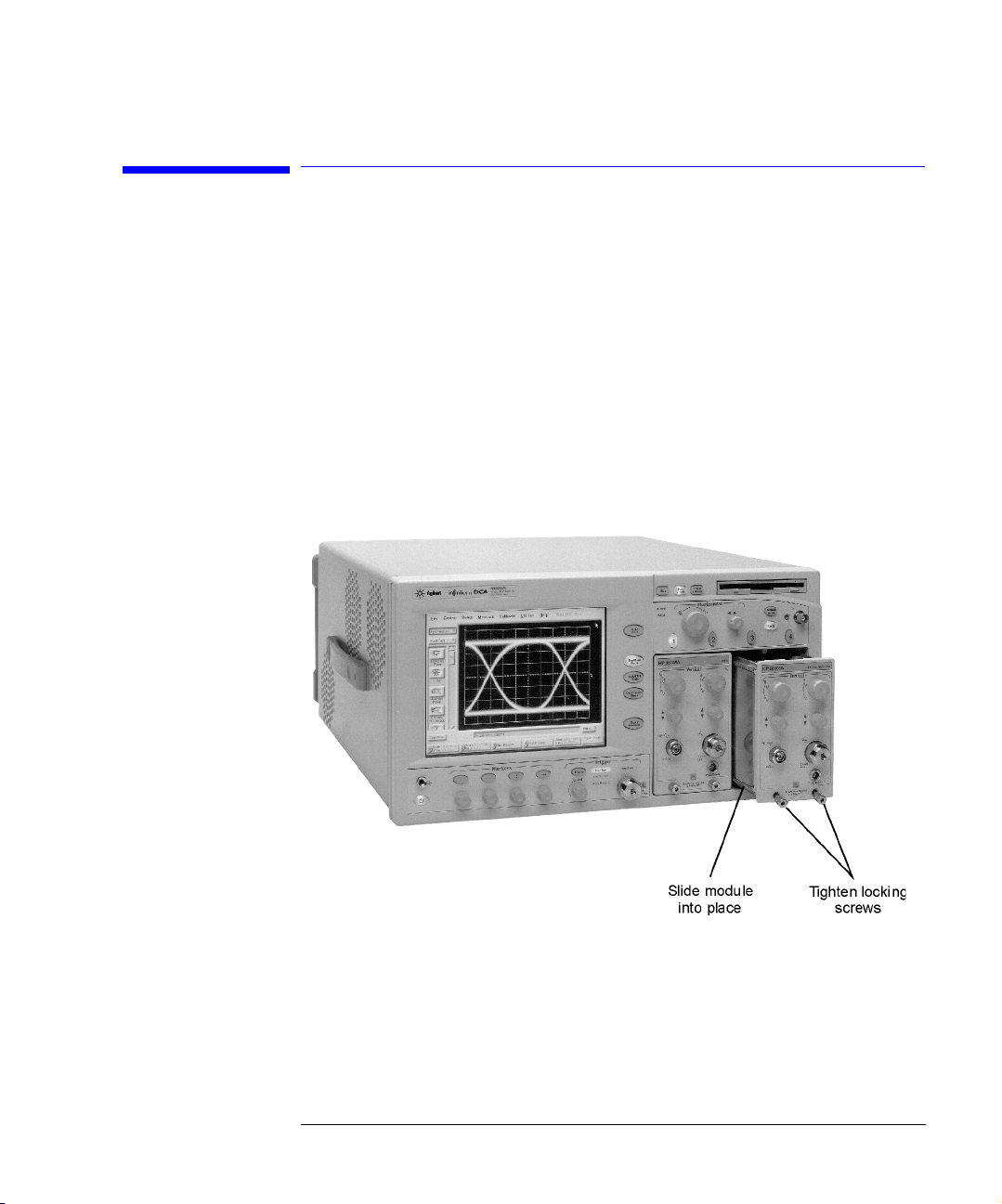
Step 2. Install any Modules
Up to two modules can be inserted into the Infiniium DCA. All documentation
(including specifications) for plug-in modules is located in the Infiniium DCA’s
Help system. To access the Help, touch or click Contents on the Help menu.
1 Slide the module into an available front-panel slot.
You can remove or install a module while the instrument is operating.
2 Finger tighten the two knurled screws on the module’s front panel.
1-9
Page 14

Setting Up the Infiniium DCA
Step 3. Consider Environmental Specifications
Step 3. Consider Environmental Specifications
Review the following specifications to ensure that your operating or storage
environment is suitable for the instrument.
Table 1-6. Environmental Specifications
Use indoor
Temperature
Operating 10 °C to +40 °C (50 °F to + 104 °F)
Non-operating -40 °C to +70 °C (-40 °F to +158 °F)
Humidity
Operating Up to 90% humidity (non-condensing) at +40 °C (+104 °F)
Non-operating Up to 95% relative humidity at + 65 °C (+149 °F)
Altitude
Operating Up to 4,600 meters (15,000 ft)
Non-operating Up to 15,300 meters (50,000 ft)
Vibration
Operating Random vibration 5-500 Hz, 10 minutes per axis, 2.41 g(rms)
Non-operating Random vibration 5-500 Hz, 10 minutes per axis, 0.3 g(rms);
Resonant search, 5-500Hz swept sine, 1 octave/minute sweep
rate, 0.75g, 5 minute resonant dwell at 4 resonances per axis.
Power requirements
Voltage 90 to 132 or 198 to 264 Vac, 48-66 Hz CAT II
Power (including modules) 545 VA; 375 W
Weight
Mainframe 15.5 kg (34 lb)
Modules 1.2 kg (2.6 lb)
Dimensions
Height 215.1 mm (8.47 in)
Width 425.5 mm (16.75 in)
Depth 566 mm (22.2 in)
Depth with front connectors
and rear feet
629 mm (24.8 in)
1-10
Page 15
Setting Up the Infiniium DCA
Step 4. Connect the Keyboard and Mouse (Optional)
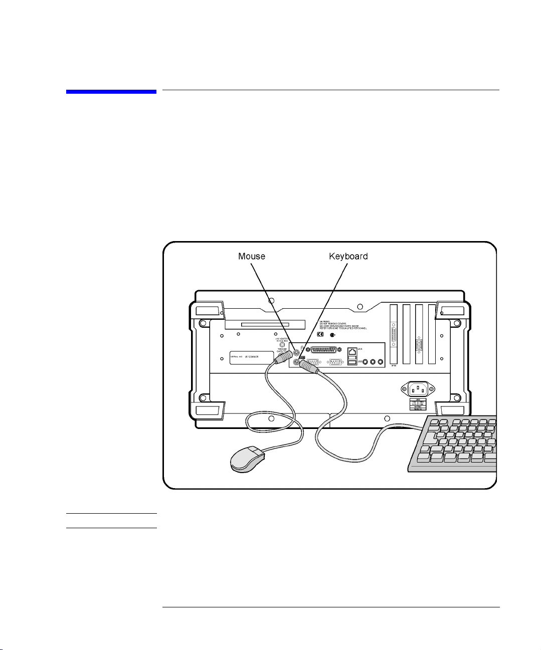
Step 4. Connect the Keyboard and Mouse
(Optional)
Connect the standard PC-compatible mouse and keyboard that is supplied
with the instrument.
NOTE Do not stack other objects on the keyboard; this will cause self-test failures on power-on.
1-11
Page 16

Setting Up the Infiniium DCA
Step 5. Connect the Line Cord
Step 5. Connect the Line Cord
Connect the line cord as shown in the figure below.
The Infiniium DCA automatically adjusts for line input voltages in the range of
100 to 240 VAC. There is no manual selection switch. The line cord provided is
matched by Agilent to the country in which the order originates. Refer to
Table 1-8, “Available Line Cords,” on page 1-13 for a list of available line power
cords.
Install the instrument so that the detachable power cord is readily identifiable
and is easily reached by the operator. The detachable power cord is the
instrument disconnecting device. It disconnects the mains circuits from the
mains supply before other parts of the instrument. The front panel switch is
1-12
Page 17
Setting Up the Infiniium DCA
Step 5. Connect the Line Cord
only a standby switch and is not a LINE switch. Alternatively, an externally
installed switch or circuit breaker (which is readily identifiable and is easily
reached by the operator) may be used as a disconnecting device.
CAUTION Always use the three-prong AC power cord supplied with this instrument.
Failure to ensure adequate earth grounding by not using this cord may cause
instrument damage.
CAUTION Do not connect ac power until you have verified the line voltage is correct as
described in Table 1-7. Damage to the equipment could result.
CAUTION This instrument has autoranging line voltage input. Be sure the supply voltage
is within the specified range.
Table 1-7. Line Power Requirements
Power 115 VAC: 110 VA MAX. / 60 WATTS MAX. / 1.1 A MAX.
230 VAC: 150 VA MAX. / 70 WATTS MAX. / 0.6 A MAX.
Voltage nominal: 115 VAC / 230 VAC CAT II
range 115 VAC: 90–132 V
range 230 VAC: 198–254 V
Frequency nominals: 50 Hz / 60 Hz
range: 47–63 Hz
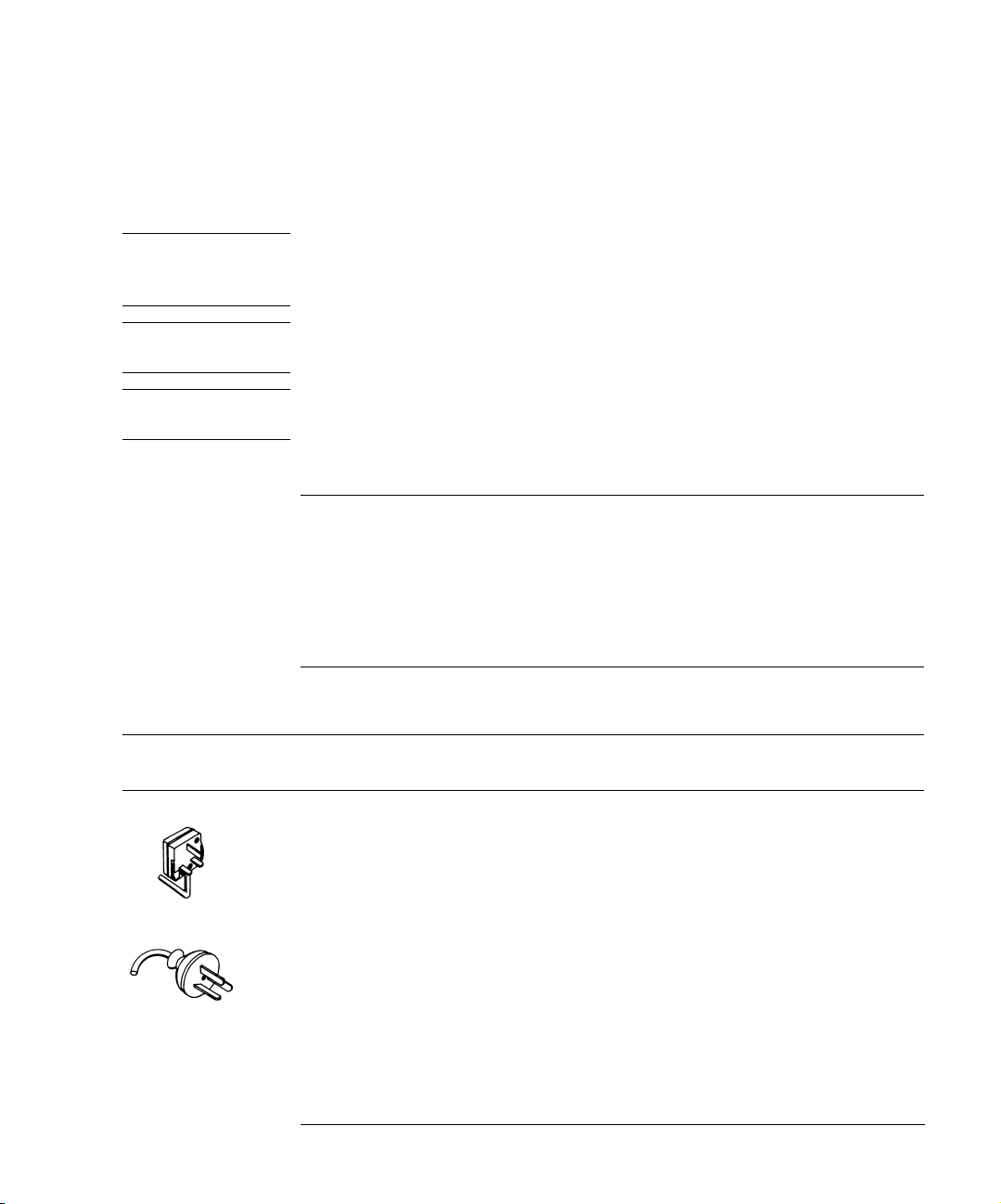
Table 1-8. Available Line Cords
Plug Type Cable Part No. Plug Description
250V 8120-1351
8120-1703
250V 8120-1369
8120-0696
Straight *BS1363A
90°
Straight *NZSS198/ASC
90°
Length
(in/cm)
90/228
90/228
79/200
87/221
Color Country
Gray
Mint Gray
Gray
Mint Gray
United Kingdom, Cyprus,
Nigeria, Zimbabwe,
Singapore
Australia, New Zealand
1-13
Page 18
Setting Up the Infiniium DCA
Step 5. Connect the Line Cord
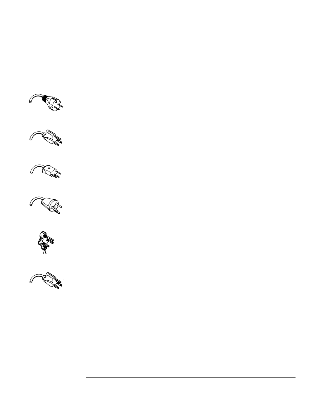
Table 1-8. Available Line Cords
Plug Type Cable Part No. Plug Description
250V 8120-1689
8120-1692
8120-2857p
125V 8120-1378
8120-1521
8120-1992
250V 8120-2104
8120-2296
Straight *CEE7-Y11
90°
Straight (Shielded)
Straight *NEMA5-15P
90°
Straight (Medical) UL544
Straight *SEV1011
1959-24507
Type 12 90°
220V 8120-2956
8120-2957
250V 8120-4211
8120-4600
Straight *DHCK107
90°
Straight SABS164
90°
Length
(in/cm)
79/200
79/200
79/200
90/228
90/228
96/244
79/200
79/200
79/200
79/200
79/200
79/200
Color Country
Mint Gray
Mint Gray
Coco Brown
Jade Gray
Jade Gray
East and West Europe,
Saudi Arabia, So. Africa,
India (unpolarized in many
nations)
United States, Canada,
Mexico, Philippines,
Taiwan
Black
Mint Gray
Switzerland
Mint Gray
Mint Gray
Denmark
Mint Gray
Jade Gray Republic of South Africa
India
100V 8120-4753
8120-4754
* Part number shown for plug is the industry identifier for the plug only. Number shown for
cable is the Agilent Technologies part number for the complete cable including the plug.
1-14
Straight MITI
90°
90/230
90/230
Dark Gray Japan
Page 19
Step 6. Turn on the line power
Setting Up the Infiniium DCA
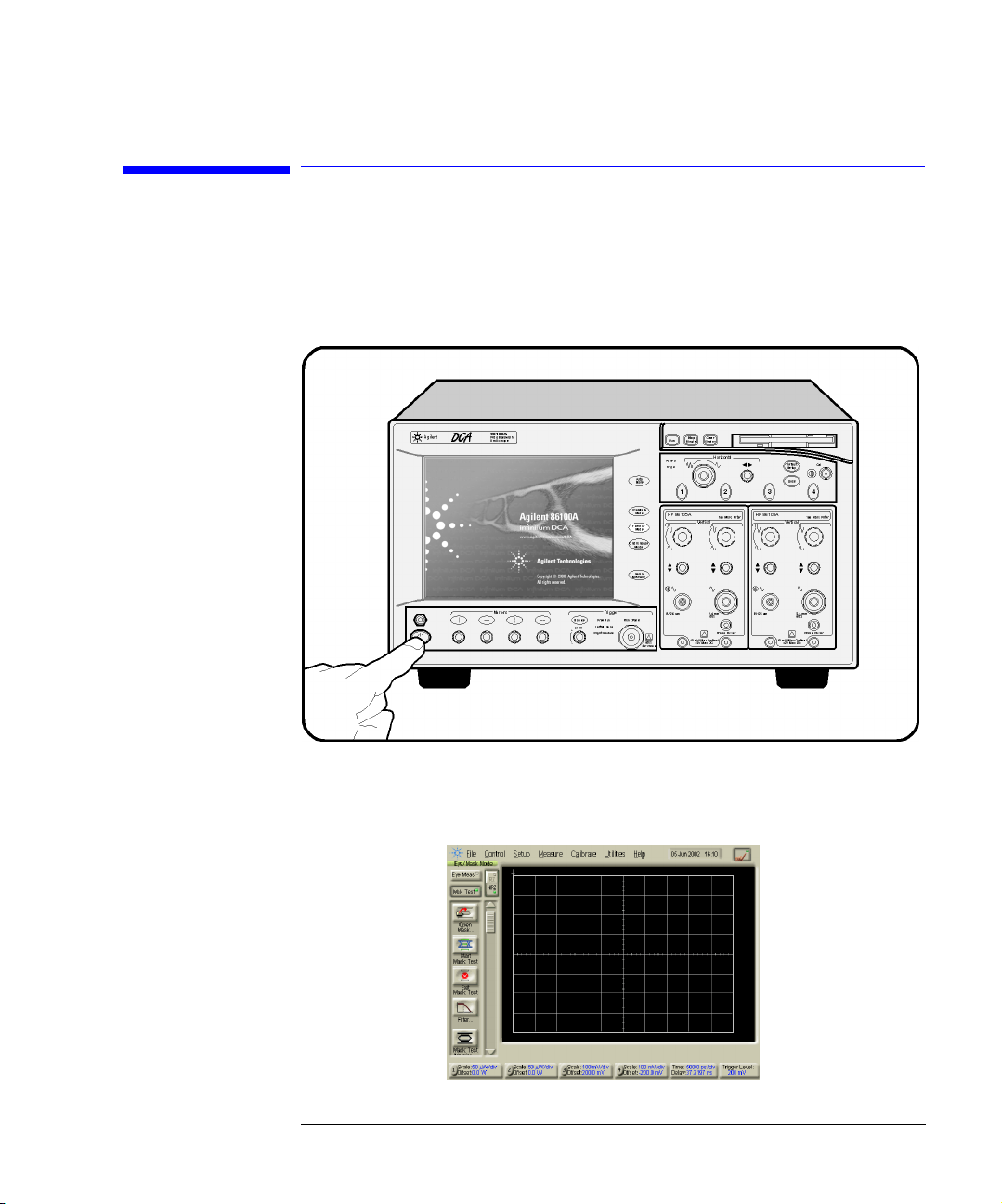
Step 6. Turn on the line power
Press the power switch at the lower left-hand corner of the front panel.
After about one minute, the Infiniium DCA will be ready to use. The display
will look similar to the following figure.
1-15
Page 20

Setting Up the Infiniium DCA
Interacting With the Display
NOTE The detachable power cord is the instrument disconnecting device. It disconnects the
mains circuits from the mains power supply before other parts of the instrument. The
front panel switch is only a standby switch and is not a LINE switch disconnecting
device.
Install the instrument so that the detachable power cord is readily identifiable and is
easily reached by the operator.
Interacting With the Display
Although you can operate all instrument functions using a keyboard and
mouse, the touch screen feature makes your Infiniium DCA even easier to use.
You can explore the instrument’s functions and settings by touching elements
on the display (such as menus, buttons, and other controls) with your finger
or the supplied stylus.
Although this book uses the term “touch” to encourage you to experience
using the touch screen, you can always click using a mouse or PC-compatible
pointing device instead.
NOTE The display will always function as a touch screen, even when a mouse and keyboard are
connected.
CAUTION Avoid touching the screen with a sharp object, as this could result in damage to
the display. Use your finger or the supplied stylus.
1-16
Page 21
Setting Up the Infiniium DCA
Step 7. Set the time and date
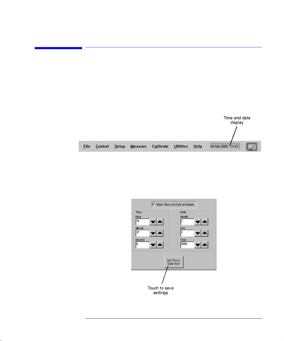
Step 7. Set the time and date
1 Touch the current time and date shown near the top of the display. The Set
Tim e and Date dialog box opens.
2 Enter the current time and date in one of the following ways:
• Click the time and date text boxes, and enter the desired number.
• Click the up or down arrows next to the time and date text boxes until the
desired number is displayed.
3 Touch Set Time & Date Now to apply the changes and close the dialog box.
1-17
Page 22

Setting Up the Infiniium DCA
Step 8. Connect a Printer
Step 8. Connect a Printer
Use of a printer with the Infiniium DCA is optional. Table 1 -9 lists the PCL-language printers that are currently supported for use with the instrument. To
add a local printer, you must use the Add Printer Wizard to select the printer
driver for the printer as outlined in this procedure; the Add Printer Wizard
does not run automatically. For more information on connecting and using a
printer, refer to the built-in information system. To add a network printer, contact your network administrator.
Unsupported printers
If your printer is not in the list of supported printers, you will need the printer driver disk
that came with your printer. To install the printer driver from this disk, click Have Disk on
the Add Printer Wizard dialog box. The instrument will then prompt you to put your
printer driver disk into the front-panel disk drive (drive A) or rear-panel CD-Rom drive.
Be sure to install the Windows 98 printer driver for your printer. If a printer driver disk
was not provided or you cannot find the disk, you can contact the printer’s manufacturer
to obtain the appropriate Windows 98 printer driver.
Table 1-9. Supported Printers
HP DeskJet 850 HP DeskJet 1600C
HP DeskJet 890C HP LaserJet 4P
HP DeskJet 970 HP LaserJet 4000N
HP DeskJet 1200C
To connect a printer
1 Turn on the power to the Infiniium DCA.
2 On the File menu, select Print Setup and then Add Printer.
An online Help window opens with instructions for connecting a printer. You
do not need to read the displayed instructions at this time.
1-18
Page 23

Setting Up the Infiniium DCA
Step 8. Connect a Printer
3 Turn the power off the Infiniium DCA. Do not exit the online Help before
turning the instrument off.
4 Connect the printer to the instrument’s rear-panel Parallel port. Refer to
“Rear-panel features” on page 3-6 to locate the Parallel port. Use the cable
that came with your printer.
5 Turn the printer power on.
6 Wait five seconds and then turn the power on the Infiniium DCA again.
7 The following message appears. Touch No.
8 The following message appears. Touch OK.
9 The instrument
automatically recognizes
the printer connected on
the printer port and
displays the Add Printer
Wizard. Touch Next.
1-19
Page 24

Setting Up the Infiniium DCA
Step 8. Connect a Printer
10 Select Local printer and
then touch Next.
11 Select the printer
manufacturer and then
printer. Then, touch
Next. If your printer is
not listed, touch Have
Disk. The instrument
will then prompt you to
put your printer driver
disk into the front-panel
disk drive (drive A) or
CD-Rom drive. Be sure
to install the Windows 98
printer driver for your
printer.
12 Select LPT1 for the
printer port. Touch
Next.
1-20
Page 25
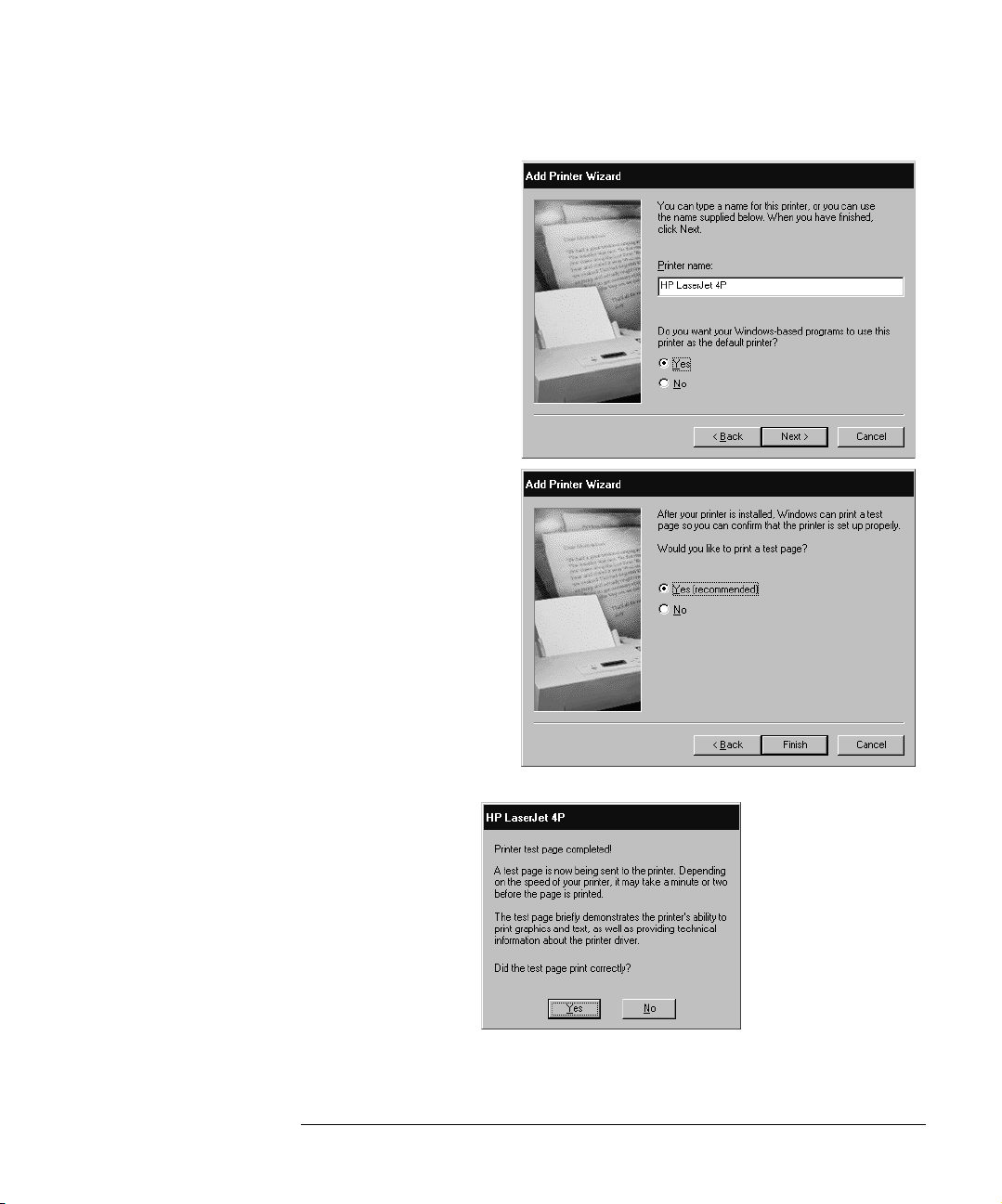
13 Touch Yes and then
touch Next.
14 Touch Yes to print a test
page. Then, touch Next.
15 After confirming that the
test page printed
correctly, touch Yes.
Setting Up the Infiniium DCA
Step 8. Connect a Printer
16 Turn the Infiniium DCA’s power off and then on again. The printer is now
installed and ready to use.
1-21
Page 26

Setting Up the Infiniium DCA
Step 9. Calibrate the Touch Screen
Step 9. Calibrate the Touch Screen
The touch screen configuration utility ensures that the touch screen is both
aligned and orientated with the display. Therefore, when you touch an element on the display screen, the instrument can detect the task you want to
perform.
1 On the Utilities menu, choose Touch Screen Calibration. The touch screen
configuration utility opens.
2 Touch the center of the X. The X will move to each corner of the display screen.
The final X will appear in the center of the display screen. When the display is
calibrated, the touch screen configuration utility closes.
The calibration will time out within 10 seconds if you do not touch the center
of the X. You can also press Esc on an optional keyboard to exit the touch
screen calibration.
1-22
Page 27

Setting Up the Infiniium DCA
Step 10. Configure the Instrument on a LAN
Step 10. Configure the Instrument on a LAN
You can configure this instrument on a LAN for file sharing and using network
printers. Contact your company’s network administrator to set up your instrument with the appropriate client, protocol, and configuration for your local
area network (LAN). The network setup is different for every company. If you
plan on sharing your instrument hard disk drive with other computers on your
LAN, you should have the network administrator enable file sharing as part of
the network setup. For more information on setting up a network drive, refer
to the built-in information system.
1-23
Page 28

Setting Up the Infiniium DCA
Step 11. Avoid Costly Repairs
Step 11. Avoid Costly Repairs
CAUTION Electrical channel input circuits and the trigger input circuit can be damaged
by electrostatic discharge (ESD). Therefore, avoid applying static discharges
to the front-panel input connectors. Prior to connecting any coaxial cable to
the connectors, momentarily short the center and outer conductors of the
cable together. Avoid touching the front-panel input connectors without first
touching the frame of the instrument. Be sure that the instrument is properly
earth-grounded to prevent buildup of static charge. Wear a wrist-strap or heelstrap.
CAUTION Optical channel fiber-optic connectors are easily damaged when connected to
dirty or damaged cables and accessories. When you use improper cleaning and
handling techniques, you risk expensive instrument repairs, damaged cables,
1-24
Page 29

Setting Up the Infiniium DCA
Step 11. Avoid Costly Repairs
and compromised measurements. Before you connect any fiber-optic cable to
the Infiniium DCA, refer to “Cleaning Connections for Accurate
Measurements” on page 1-30.
1-25
Page 30

Setting Up the Infiniium DCA
Step 12. Perform a Module Calibration
Step 12. Perform a Module Calibration
A module calibration establishes calibration factors for all installed modules.
The calibration factors compensate for imperfections in the measurement system (for example, variations due to ambient temperature), resulting in the
best instrument precision. It is recommended that you perform this calibration
routinely for best measurement accuracy.
The module calibration is recommended whenever the following occurs:
• Instrument power has been cycled
• A module has been removed and then reinserted
• A change in the temperature of the mainframe exceeds 5°C compared to the
temperature of the last vertical (amplitude) calibration (∆T > 5°C)
• The time since the last calibration has exceeded 10 hours
Refer to the Help for more information about instrument calibrations.
Warm-up time
Allow the instrument, with modules installed, to warm up for a period of at least one
hour before performing a vertical calibration. This ensures that the module reaches its
equilibrium temperature.
CAUTION Electrical channel input circuits and the trigger input circuit can be damaged
by electrostatic discharge (ESD). Therefore, avoid applying static discharges
to the front-panel input connectors. Prior to connecting any coaxial cable to
the connectors, momentarily short the center and outer conductors of the
cable together. Avoid touching the front-panel input connectors without first
touching the frame of the instrument. Be sure that the instrument is properly
earth-grounded to prevent buildup of static charge. Wear a wrist-strap or heelstrap.
1-26
Page 31

Setting Up the Infiniium DCA
Step 12. Perform a Module Calibration
To perform a module calibration
1 On the Calibrate menu, choose All Calibrations.
The All Calibrations dialog box opens. This dialog box allows you to view
the calibration status of modules and initiate the calibration.
2 Touch the Modules tab.
The Modules tab opens and allows you to perform a module calibration on
either the left or right module.
3 Touch the Calibrate Module button (located at the bottom of
the tab) for the module you need to calibrate. This starts the
Module calibration.
4 Remove all external devices and signals from the module.
The module calibration uses known signal levels in the instrument. Introducing an outside signal source will interfere with the calibration factors and
decrease the accuracy of the calibration.
5 Touch Continue. A progress indicator appears.
6 After the calibration completes, choose All Calibrations on the Calibration
menu.
7 The Module tab shows the status of the calibration. The tab will look similar to
the following figure. Notice that the tab indicates that the “Current user
1-27
Page 32

Setting Up the Infiniium DCA
Step 12. Perform a Module Calibration
module calibration is valid.”
1-28
Page 33

Setting Up the Infiniium DCA
Step 13. For More Information
Step 13. For More Information
There are several ways to learn more about your Infiniium DCA.
• Continue reading this book. Chapter 3, “Using the Infiniium DCA” will help you
get started using this instrument.
• Refer to the Help. The Help contains the information that would normally be in
the user’s guide.
• Visit our website at http://www.agilent.com. Use the keywords “Infiniium
DCA” or “86100B” in your search
1-29
Page 34

Setting Up the Infiniium DCA
Cleaning Connections for Accurate Measurements
Cleaning Connections for Accurate
Measurements
Today, advances in measurement capabilities make connectors and connection techniques more important than ever. Damage to the connectors on calibration and verification devices, test ports, cables, and other devices can
degrade measurement accuracy and damage instruments. Replacing a damaged connector can cost thousands of dollars, not to mention lost time! This
expense can be avoided by observing the simple precautions presented in this
book. This book also contains a brief list of tips for caring for electrical connectors.
Choosing the Right Connector
A critical but often overlooked factor in making a good lightwave measurement is the selection of the fiber-optic connector. The differences in connector types are mainly in the mechanical assembly that holds the ferrule in
position against another identical ferrule. Connectors also vary in the polish,
curve, and concentricity of the core within the cladding. Mating one style of
cable to another requires an adapter. Agilent Technologies offers adapters for
most instruments to allow testing with many different cables. Figure 1-1 on
page 1-31 shows the basic components of a typical connectors.
The system tolerance for reflection and insertion loss must be known when
selecting a connector from the wide variety of currently available connectors.
Some items to consider when selecting a connector are:
• How much insertion loss can be allowed?
• Will the connector need to make multiple connections? Some connectors are
better than others, and some are very poor for making repeated connections.
• What is the reflection tolerance? Can the system take reflection degradation?
• Is an instrument-grade connector with a precision core alignment required?
• Is repeatability tolerance for reflection and loss important? Do your specifica-
1-30
Page 35

Setting Up the Infiniium DCA
Choosing the Right Connector
tions take repeatability uncertainty into account?
• Will a connector degrade the return loss too much, or will a fusion splice be required? For example, many DFB lasers cannot operate with reflections from
connectors. Often as much as 90 dB isolation is needed.
Figure 1-1. Basic components of a connector.
Over the last few years, the FC/PC style connector has emerged as the most
popular connector for fiber-optic applications. While not the highest performing connector, it represents a good compromise between performance, reliability, and cost. If properly maintained and cleaned, this connector can
withstand many repeated connections.
However, many instrument specifications require tighter tolerances than most
connectors, including the FC/PC style, can deliver. These instruments cannot
tolerate connectors with the large non-concentricities of the fiber common
with ceramic style ferrules. When tighter alignment is required, Agilent
Technologies instruments typically use a connector such as the Diamond
HMS-10, which has concentric tolerances within a few tenths of a micron. Agilent Technologies then uses a special universal adapter, which allows other
cable types to mate with this precision connector. See Figure 1-2.
1-31
Page 36

Setting Up the Infiniium DCA
Choosing the Right Connector
Figure 1-2. Universal adapters to Diamond HMS-10.
The HMS-10 encases the fiber within a soft nickel silver (Cu/Ni/Zn) center
which is surrounded by a tough tungsten carbide casing, as shown in
Figure 1-3.
Figure 1-3. Cross-section of the Diamond HMS-10 connector.
The nickel silver allows an active centering process that permits the glass fiber
to be moved to the desired position. This process first stakes the soft nickel
silver to fix the fiber in a near-center location, then uses a post-active staking
to shift the fiber into the desired position within 0.2 µm. This process, plus the
keyed axis, allows very precise core-to-core alignments. This connector is
found on most Agilent Technologies lightwave instruments.
The soft core, while allowing precise centering, is also the chief liability of the
connector. The soft material is easily damaged. Care must be taken to minimize excessive scratching and wear. While minor wear is not a problem if the
1-32
Page 37

Setting Up the Infiniium DCA
Inspecting Connectors
glass face is not affected, scratches or grit can cause the glass fiber to move
out of alignment. Also, if unkeyed connectors are used, the nickel silver can be
pushed onto the glass surface. Scratches, fiber movement, or glass contamination will cause loss of signal and increased reflections, resulting in poor return
loss.
Inspecting Connectors
Because fiber-optic connectors are susceptible to damage that is not immediately obvious to the naked eye, bad measurements can be made without the
user even being aware of a connector problem. Although microscopic examination and return loss measurements are the best way to ensure good connections, they are not always practical. An awareness of potential problems, along
with good cleaning practices, can ensure that optimum connector performance is maintained. With glass-to-glass interfaces, it is clear that any degradation of a ferrule or the end of the fiber, any stray particles, or finger oil can
have a significant effect on connector performance.
Figure 1-4 shows the end of a clean fiber-optic cable. The dark circle in the
center of the micrograph is the fiber’s 125 µm core and cladding which carries
the light. The surrounding area is the soft nickel-silver ferrule. Figure 1-5
shows a dirty fiber end from neglect or perhaps improper cleaning. Material is
smeared and ground into the end of the fiber causing light scattering and poor
reflection. Not only is the precision polish lost, but this action can grind off the
glass face and destroy the connector.
Figure 1-6 shows physical damage to the glass fiber end caused by either
repeated connections made without removing loose particles or using
improper cleaning tools. When severe, the damage on one connector end can
be transferred to another good connector that comes in contact with it.
The cure for these problems is disciplined connector care as described in the
following list and in “Cleaning Connectors” on page 1-36.
Use the following guidelines to achieve the best possible performance when
making measurements on a fiber-optic system:
• Never use metal or sharp objects to clean a connector and never scrape the
connector.
• Avoid matching gel and oils.
1-33
Page 38

Setting Up the Infiniium DCA
Inspecting Connectors
Figure 1-4. Clean, problem-free fiber end and ferrule.
Figure 1-5. Dirty fiber end and ferrule from poor cleaning.
Figure 1-6. Damage from improper cleaning.
While these often work well on first insertion, they are great dirt magnets. The
oil or gel grabs and holds grit that is then ground into the end of the fiber.
Also, some early gels were designed for use with the FC, non-contacting con-
1-34
Page 39

Setting Up the Infiniium DCA
Inspecting Connectors
nectors, using small glass spheres. When used with contacting connectors,
these glass balls can scratch and pit the fiber. If an index matching gel or oil
must be used, apply it to a freshly cleaned connector, make the measurement,
and then immediately clean it off. Never use a gel for longer-term connections
and never use it to improve a damaged connector. The gel can mask the extent
of damage and continued use of a damaged fiber can transfer damage to the
instrument.
• When inserting a fiber-optic cable into a connector, gently insert it in as
straight a line as possible. Tipping and inserting at an angle can scrape material
off the inside of the connector or even break the inside sleeve of connectors
made with ceramic material.
• When inserting a fiber-optic connector into a connector, make sure that the fiber end does not touch the outside of the mating connector or adapter.
• Avoid over tightening connections.
Unlike common electrical connections, tighter is not better. The purpose of
the connector is to bring two fiber ends together. Once they touch, tightening
only causes a greater force to be applied to the delicate fibers. With connectors that have a convex fiber end, the end can be pushed off-axis resulting in
misalignment and excessive return loss. Many measurements are actually
improved by backing off the connector pressure. Also, if a piece of grit does
happen to get by the cleaning procedure, the tighter connection is more likely
to damage the glass. Tighten the connectors just until the two fibers touch.
• Keep connectors covered when not in use.
• Use fusion splices on the more permanent critical nodes. Choose the best con-
nector possible. Replace connecting cables regularly. Frequently measure the
return loss of the connector to check for degradation, and clean every connector, every time.
All connectors should be treated like the high-quality lens of a good camera.
The weak link in instrument and system reliability is often the inappropriate
use and care of the connector. Because current connectors are so easy to use,
there tends to be reduced vigilance in connector care and cleaning. It takes
only one missed cleaning for a piece of grit to permanently damage the glass
and ruin the connector.
Measuring insertion loss and return loss
Consistent measurements with your lightwave equipment are a good indication that you have good connections. Since return loss and insertion loss are
key factors in determining optical connector performance they can be used to
determine connector degradation. A smooth, polished fiber end should pro-
1-35
Page 40

Setting Up the Infiniium DCA
Cleaning Connectors
duce a good return-loss measurement. The quality of the polish establishes
the difference between the “PC” (physical contact) and the “Super PC” connectors. Most connectors today are physical contact which make glass-to-glass
connections, therefore it is critical that the area around the glass core be clean
and free of scratches. Although the major area of a connector, excluding the
glass, may show scratches and wear, if the glass has maintained its polished
smoothness, the connector can still provide a good low level return loss connection.
If you test your cables and accessories for insertion loss and return loss upon
receipt, and retain the measured data for comparison, you will be able to tell in
the future if any degradation has occurred. Typical values are less than 0.5 dB
of loss, and sometimes as little as 0.1 dB of loss with high performance connectors. Return loss is a measure of reflection: the less reflection the better
(the larger the return loss, the smaller the reflection). The best physically
contacting connectors have return losses better than 50 dB, although 30 to
40 dB is more common.
Visual inspection of fiber ends
Visual inspection of fiber ends can be helpful. Contamination or imperfections
on the cable end face can be detected as well as cracks or chips in the fiber
itself. Use a microscope (100X to 200X magnification) to inspect the entire
end face for contamination, raised metal, or dents in the metal as well as any
other imperfections. Inspect the fiber for cracks and chips. Visible imperfections not touching the fiber core may not affect performance (unless the
imperfections keep the fibers from contacting).
Cleaning Connectors
The procedures in this section provide the proper steps for cleaning fiberoptic cables and Agilent Technologies universal adapters. The initial cleaning,
using the alcohol as a solvent, gently removes any grit and oil. If a caked-on
layer of material is still present, (this can happen if the beryllium-copper sides
of the ferrule retainer get scraped and deposited on the end of the fiber during
insertion of the cable), a second cleaning should be performed. It is not
uncommon for a cable or connector to require more than one cleaning.
CAUTION Agilent Technologies strongly recommends that index matching compounds
not be applied to their instruments and accessories. Some compounds, such as
gels, may be difficult to remove and can contain damaging particulates. If you
think the use of such compounds is necessary, refer to the compound
manufacturer for information on application and cleaning procedures.
1-36
Page 41

Setting Up the Infiniium DCA
Table 1-10. Cleaning Accessories
Item Agilent Part Number
Isopropyl alcohol 8500-5344
Cotton swabs 8520-0023
Small foam swabs 9300-1223
Compressed dust remover (non-residue) 8500-5262
Table 1-11. Dust Caps Provided with Lightwave Instruments
Item Agilent Part Number
Laser shutter cap 08145-64521
FC/PC dust cap 08154-44102
Biconic dust cap 08154-44105
DIN dust cap 5040-9364
HMS10/dust cap 5040-9361
ST dust cap 5040-9366
Cleaning Connectors
To clean a non-lensed connector
CAUTION Do not use any type of foam swab to clean optical fiber ends. Foam swabs can
leave filmy deposits on fiber ends that can degrade performance.
1 Apply pure isopropyl alcohol to a clean lint-free cotton swab or lens paper.
Cotton swabs can be used as long as no cotton fibers remain on the fiber end
after cleaning.
2 Clean the ferrules and other parts of the connector while avoiding the end of
the fiber.
3 Apply isopropyl alcohol to a new clean lint-free cotton swab or lens paper.
4 Clean the fiber end with the swab or lens paper.
Do not scrub during this initial cleaning because grit can be caught in the
swab and become a gouging element.
5 Immediately dry the fiber end with a clean, dry, lint-free cotton swab or lens
paper.
6 Blow across the connector end face from a distance of 6 to 8 inches using
1-37
Page 42

Setting Up the Infiniium DCA
Cleaning Connectors
filtered, dry, compressed air. Aim the compressed air at a shallow angle to the
fiber end face.
Nitrogen gas or compressed dust remover can also be used.
CAUTION Do not shake, tip, or invert compressed air canisters, because this releases
particles in the can into the air. Refer to instructions provided on the
compressed air canister.
7 As soon as the connector is dry, connect or cover it for later use.
If the performance, after the initial cleaning, seems poor try cleaning the connector again. Often a second cleaning will restore proper performance. The
second cleaning should be more arduous with a scrubbing action.
To clean an adapter
The fiber-optic input and output connectors on many Agilent Technologies
instruments employ a universal adapter such as those shown in the following
picture. These adapters allow you to connect the instrument to different types
of fiber-optic cables.
Figure 1-7. Universal adapters.
1 Apply isopropyl alcohol to a clean foam swab.
Cotton swabs can be used as long as no cotton fibers remain after cleaning. The
foam swabs listed in this section’s introduction are small enough to fit into
adapters.
Although foam swabs can leave filmy deposits, these deposits are very thin, and
the risk of other contamination buildup on the inside of adapters greatly outweighs the risk of contamination by foam swabs.
2 Clean the adapter with the foam swab.
3 Dry the inside of the adapter with a clean, dry, foam swab.
4 Blow through the adapter using filtered, dry, compressed air.
Nitrogen gas or compressed dust remover can also be used. Do not shake, tip,
or invert compressed air canisters, because this releases particles in the can
into the air. Refer to instructions provided on the compressed air canister.
1-38
Page 43

Setting Up the Infiniium DCA
Returning the Instrument for Service
Returning the Instrument for Service
The instructions in this section show you how to properly package the instrument for return to a Agilent Technologies service office. For a list of offices,
refer to “Agilent Technologies Service Offices” on page 1-43.
If the instrument is still under warranty or is covered by an Agilent maintenance contract, it will be repaired under the terms of the warranty or contract
(the warranty is at the front of this manual). If the instrument is no longer
under warranty or is not covered by an Agilent maintenance plan, Agilent will
notify you of the cost of the repair after examining the unit.
When an instrument is returned to a Agilent service office for servicing, it
must be adequately packaged and have a complete description of the failure
symptoms attached.
When describing the failure, please be as specific as possible about the nature
of the problem. Include copies of additional failure information (such as the
instrument failure settings, data related to instrument failure, and error messages) along with the original cal data disks and the instrument being
returned.
Please notify the service office before returning your instrument for service.
Any special arrangements for the instrument can be discussed at this time.
This will help the Agilent service office repair and return your instrument as
quickly as possible.
Preparing the instrument for shipping
1 Write a complete description of the failure and attach it to the instrument.
Include any specific performance details related to the problem. The following
1-39
Page 44

Setting Up the Infiniium DCA
Preparing the instrument for shipping
information should be returned with the instrument.
• Type of service required.
• Date instrument was returned for repair.
• Description of the problem:
• Whether problem is constant or intermittent.
• Whether instrument is temperature-sensitive.
• Whether instrument is vibration-sensitive.
• Instrument settings required to reproduce the problem.
• Performance data.
• Company name and return address.
• Name and phone number of technical contact person.
• Model number of returned instrument.
• Full serial number of returned instrument.
• List of any accessories returned with instrument.
• The original cal data disks.
2 Cover all front or rear-panel connectors that were originally covered when you
first received the instrument.
CAUTION Cover electrical connectors to protect sensitive components from electrostatic
damage. Cover optical connectors to protect them from damage due to physical
contact or dust.
CAUTION Instrument damage can result from using packaging materials other than the
original materials. Never use styrene pellets as packaging material. They do not
adequately cushion the instrument or prevent it from shifting in the carton.
They may also cause instrument damage by generating static electricity.
3 Pack the instrument in the original shipping containers. Original materials are
available through any Agilent office. Or, use the following guidelines:
• Wrap the instrument in antistatic plastic to reduce the possibility of damage
caused by electrostatic discharge.
• For instruments weighing less than 54 kg (120 lb), use a double-walled, corrugated cardboard carton of 159 kg (350 lb) test strength.
• The carton must be large enough to allow approximately 7 cm (3 inches) on
all sides of the instrument for packing material, and strong enough to accommodate the weight of the instrument.
• Surround the equipment with approximately 7 cm (3 inches) of packing material, to protect the instrument and prevent it from moving in the carton. If
packing foam is not available, the best alternative is S.D-240 Air Cap™ from
1-40
Page 45

Setting Up the Infiniium DCA
Preparing the instrument for shipping
Sealed Air Corporation (Commerce, California 90001). Air Cap looks like a
plastic sheet filled with air bubbles. Use the pink (antistatic) Air Cap™ to
reduce static electricity. Wrapping the instrument several times in this material will protect the instrument and prevent it from moving in the carton.
4 Seal the carton with strong nylon adhesive tape.
5 Mark the carton “FRAGILE, HANDLE WITH CARE”.
6 Retain copies of all shipping papers.
1-41
Page 46

Setting Up the Infiniium DCA
Hard Drive Recovery
Hard Drive Recovery
The Infiniium DCA hard drive recovery system offers a way to recover from
situations when the instrument hard drive configuration becomes corrupt due
to inadvertent user changes to the instrument or to a virus infection.
The Infiniium DCA hard disk recovery system consists one floppy disk, one
CD-ROM, and instructions. The recovery process will re-image the internal
disk drive on the Agilent 86100B. After the recovery process is complete, the
Infiniium DCA firmware is set to the latest revision as indicated on the recovery disks.
NOTE Please be advised that all user files and the user network configuration settings will be
lost during the recovery process.
To order a free hard drive recovery package, visit
http://www.agilent.com/comms/dca
1-42
Page 47

Setting Up the Infiniium DCA
Agilent Technologies Service Offices
Agilent Technologies Service Offices
Call Center
For technical assistance, you can contact your local Agilent Call Center.
• In the Americas, call 1 (800) 452-4844
• In other regions, visit http://www.agilent.com and click Contact Us.
Service Center
Before returning an instrument for service, you must first call the Agilent
Technologies Instrument Support Center.
• In all regions, call (800) 403-0801
1-43
Page 48

Setting Up the Infiniium DCA
Service Center
1-44
Page 49

2
Working in Comfort
Page 50

Working in Comfort
Working in Comfort
Working in Comfort
To optimize your comfort and productivity, it is important that you set up your
work area correctly and use your Agilent product properly. With that in mind,
we have developed some setup and use recommendations for you to follow
based on established ergonomic principles.
Improper and prolonged use of keyboards and input devices are among those
tasks that have been associated with repetitive strain injury (RSI) to soft tissues in the hands and arms. If you experience discomfort or pain while using
your Agilent Technologies product, discontinue use immediately and consult
your physician as soon as possible.
Please study the recommendations offered here in this chapter. You may also
wish to consult your employer’s human resources department or other relevant departments for guidance specific to your company.
About Repetitive Strain Injury
Because your comfort and safety are our primary concern, we strongly recommend that you use the infiniium DCA in accordance with established ergonomic principles and recommendations. Scientific literature suggests that
there may be a relationship between injury to soft tissues - especially in the
hands and arms - and prolonged improper use of keyboards or other equipment requiring repeated motions of the hands and forearms. This literature
also suggests that there are many other risk factor that may increase the
chance of such injury, commonly called Repetitive Strain Injury.
What is RSI? Repetitive Strain Injury (RSI—also known as cumulative trauma disorder or
repetitive motion injury) is a type of injury where soft tissues in the body, such
as muscles, nerves, or tendons, become irritated or inflamed. RSI has been a
reported problem for those who perform repetitive tasks such as assembly line
work, meatpacking, sewing, playing musical instruments, and computer work.
2-2
Page 51

Working in Comfort
Mice and Other Input Devices
RSI has also been observed in those who frequently engage in activities such
as carpentry, knitting, housework, gardening, tennis, windsurfing and lifting
children.
What causes RSI? The specific causes of RSI have not been established. Nevertheless, the inci-
dence of RSI has been associated with a variety of risk factors, including:
• Too many uninterrupted repetitions of an activity or motion.
• Performing an activity in an awkward or unnatural posture.
• Maintaining a static position for prolonged periods.
• Failing to take frequent short breaks.
• Other environmental and social factors.
In addition, there have been reports associating the occurrence of RSI with
the use of keyboards, mice, and other input devices. Also, certain medical conditions, such as rheumatoid arthritis, obesity and diabetes, may predispose
people to this type of injury.
What if I
experience
discomfort?
If you are experiencing any discomfort, seek professional medical advice
immediately. Typically, the earlier a problem is diagnosed and treated, the easier it is to resolve.
Mice and Other Input Devices
Various aspects of using mice and other input devices may increase your risk
of discomfort or injury. Observing the following recommendations may reduce
that risk.
• Try to keep your hand, wrist, and forearm in a neutral position while using your
mouse or other input device.
• If you use your thumb to rotate the ball on a trackball or spaceball, keep it in a
relaxed, natural shape, and maintain a neutral posture in your hand, wrist, and
forearm.
• Hold the mouse gently by draping your fingers over it. Keep your hand relaxed
and fingers loose. Do not grip the mouse tightly.
• It takes very little pressure or force from your fingers to activate the buttons or
scroll wheel on your mouse, scrolling mouse, trackball, or other input device.
Using too much force can place unnecessary stress on the tendons and muscles
2-3
Page 52

Working in Comfort
Mice and Other Input Devices
in your hands, wrists, and forearms.
• If you are using a scrolling mouse, be sure to keep your fingers and hand in a
relaxed, neutral position when activating the scroll wheel. Also, this type of
mouse features software that can minimize the number of mouse movements
or button clicks.
• When using a mouse, trackball, or other input device, position it as close to the
keyboard as possible, and keep it at the same level as you do not have to stretch
while using it.
• Use a good quality mouse pad to enable the mouse to work most effectively and
reduce unnecessary hand and wrist movements.
• Be sure to keep your mouse and trackball clean. Regular removal of accumulated dust and dirt helps ensure proper tracking and reduces unnecessary hand
and wrist motions.
2-4
Page 53

3
Introduction 3-2
Oscilloscope Mode 3-8
Eye/Mask Mode 3-7
TDR/TDT Mode 3-9
Using Plug-in Modules 3-10
Using the Touch Screen 3-12
Using the Quick Measure Feature 3-13
If the Display Goes Blank 3-14
Hiding and Moving Dialog Boxes 3-15
Menus 3-16
Using the Infiniium DCA
Page 54

Using the Infiniium DCA
Introduction
Introduction
The Infiniium DCA is designed to measure a variety of high speed digital communication waveforms. You can operate it in any of the following three instrument modes:
• Eye/Mask Mode (100 Mb/s to 10 Gb/s) for eye diagram analysis and standards
testing (for example, SONET/SDH, Gigabit Ethernet, and Fiber Channel).
• TDR/TDT Mode for time domain reflectometry measurements
• Oscilloscope Mode (DC to 20 GHz or 50 GHz)
3-2
Page 55

Using the Infiniium DCA
Introduction
Use the touch screen
You can explore the instrument’s menus and change its settings by touching
the display. Notice that the measurement toolbar changes depending on the
selected instrument mode. Touch the channel, time and delay, and trigger
level buttons located at the bottom of the display to change the horizontal and
vertical scales. Or, you can change these settings using front-panel knobs and
buttons.
3-3
Page 56

Using the Infiniium DCA
Introduction
Refer to the Help System
To learn how to use your Infiniium DCA and to locate information on specifications (including plug-in modules), instrument features, and measurement
configuration refer to Chapter 4, “Using the Built-In Information System” in
this book.
You must provide a trigger input signal
Because high-speed oscilloscopes are not capable of triggering directly on a
test signal, you must first connect an external timing reference signal to the
front-panel trigger input connector. This input allows the Infiniium DCA to
synchonize to the input signal. You can select free-run triggering when an
external trigger is unavailable. However, you will only be able to view the
waveform for amplitude information only without any timing information. This
is an easy way to examine the amplitude of a signal.
3-4
Page 57

Using the Infiniium DCA
Introduction
Front-panel features
The following figure shows the input connectors, controls, power switch, and
other front-panel features available on the Infiniium DCA.
3-5
Page 58

Using the Infiniium DCA
Introduction
Rear-panel features
The following figure shows the rear-panel input connections available on the
Infiniium DCA.
3-6
Page 59

Using the Infiniium DCA
Eye/Mask Mode
Eye/Mask Mode
The Eye/Mask mode allows you to perform NRZ (Non-Return to Zero), or RZ
(Return to Zero) eye diagram measurements and eye mask tests. The eye diagram is typically produced by triggering
the instrument with a synchronous
clock signal.
Eye/Mask mode measurements only
work when an eye diagram, and not a
pulse, is present on the screen. Measurements made on a pulse waveform
while in Eye/Mask mode will fail.
Once you are in Eye/Mask mode, press the Autoscale button. This ensures
that an optimum eye diagram is displayed on the graticule. An optimum eye
diagram consists of a full display of the eye in addition to portions of the waveform preceding and following the eye.
When you select the Eye/Mask mode, the
measurement toolbars shown here appear.
These measurement toolbars include measurements such as rise time, fall time, jitter,
and extinction ratio, as well as the mask test
start and stop controls.
Eye measurement and mask test results
appear below the display graticule. A maximum of four eye measurement test results
are displayed and include any failures or
instrument messages that may occur.
To learn more about the Eye/Mask mode and
switching from NRZ to RZ measurement
mode, consult the Help.
3-7
Page 60

Using the Infiniium DCA
Oscilloscope Mode
Oscilloscope Mode
Use the Oscilloscope mode for pulse
type waveforms that are triggered by
an external signal. Oscilloscope mode
measurements only work when a single
valued waveform, and not an eye diagram, is present on the screen.
When you select the Oscilloscope
mode, the measurement toolbars shown
here appear. These measurement toolbars
include measurements such as rise time, fall
time, overshoot, and Vp-p. All measurements, with the exception of jitter, can be
performed on any of the following sources:
channels, waveform memories, and math
functions. One of the above sources must be
turned on in order to perform an oscilloscope measurement.
If more than one source is turned on and
you initiate a measurement, the Enter Measurement Info dialog box opens. This dialog
box allows you to select the source you want
to use for the measurement.
Measurement results appear below the display graticule. A maximum of four pulse
measurement test results are displayed and include any failures or instrument
messages that may occur.
To learn more about the Oscilloscope mode, consult the Help.
3-8
Page 61

TDR/TDT Mode
The TDR/TDT mode allows you use
time domain reflectometry (TDR) to
verify the proper functioning of the
physical components of your device
under test using a time-delayed electrical pulse. You can also use time domain
transmission (TDT) to measure both
the attenuation and propagation delay
of your device under test.
TDR/TDT mode measurements when
using a single-ended or differential
TDR/TDT 5475x series plug-in module.
When you select the TDR/TDT mode, the measurement toolbar shown here appears. This measurement
toolbar includes measurements such as Quick TDR,
normalization, rise time, and fall time. Quick TDR
allows you to view an immediate display of the characteristics of your device under test. You can also use this
toolbar to perform tasks such as setting up the stimulus and destination for your measurement.
You can use markers to to verify the impedance, voltage, and percent of reflection of a selected point on the
waveform trace. TDR/TDT markers are initiated by
turning on the X-axis marker(s) only. The Y-axis
marker(s) will then track the waveform at the position
determined by the X-axis marker. You can view the
position of the marker values in the marker values tab
located below the display graticule.
To learn more about the TDR/TDT mode, consult the
Help.
Using the Infiniium DCA
TDR/TDT Mode
3-9
Page 62

Using the Infiniium DCA
Using Plug-in Modules
Using Plug-in Modules
The Infiniium DCA holds up to two plug-in modules, which can provide up to
four measurement channels. Each input channel has its own vertical controls.
The amplitude scale knob adjusts the amplitude scale used for the input channel. Use the amplitude offset knob to position the displayed signal. You can
also set the amplitude scale and offset to specific values by touching of channel buttons shown to at the bottom of the display.
To install a module
• Slide the module into an available slot and finger tighten the two front-panel
locking screws.
3-10
Page 63

Using the Infiniium DCA
Using Plug-in Modules
You can use 8348x and 5475x series plug-in modules
In addition to a complete line of modules designed specifically for this instrument, modules designed for use with HP/Agilent 83480A and 54750A mainframes can also be installed into the Infiniium DCA. The 8348x and 5475x
series plug-in modules are equipped with a trigger input on the individual
module front panels. Repeatedly press the Infiniium DCA’s front-panel Trigger
Source button until the label for the desired trigger source is lit.
CAUTION Electrical channel input circuits and the trigger input circuit can be damaged
by electrostatic discharge (ESD). Avoid applying static discharges to the frontpanel input connectors. Prior to connecting any coaxial cable to the
connectors, momentarily short the center and outer conductors of the cable
together. Avoid touching the front-panel input connectors without first
touching the frame of the instrument. Be sure that the instrument is properly
earth-grounded to prevent buildup of static charge. Wear a wrist-strap or heelstrap.
CAUTION Optical channel fiber-optic connectors are easily damaged when connected to
dirty or damaged cables and accessories. When you use improper cleaning and
handling techniques, you risk expensive instrument repairs, damaged cables,
and compromised measurements. Before you connect any fiber-optic cable to
the digital communications analyzer, refer to “Cleaning Connections for
Accurate Measurements” on page 1-30.
3-11
Page 64

Using the Infiniium DCA
Using the Touch Screen
Using the Touch Screen
There may be times when you would like to disable the touch screen feature.
For example, when pointing out a measurement result without initiating a
change to the instrument. You can temporarily disable the touch screen for
this purpose.
A touch screen configuration utility can be used to ensure that the touch
screen is both aligned and orientated with the display. It also allows you to
adjust the touch screen speed to simulate a double-click and to turn the touch
screen sound on or off.
To temporarily disable the touch screen
• Touch the disable button which is located at the top of the display. Touch the
button a second time to reenable the touch screen.
3-12
Page 65

Using the Infiniium DCA
Using the Quick Measure Feature
Using the Quick Measure Feature
Press Quick Measure and the Infiniium DCA automatically performs four
measurements on a displayed signal. You can configure Quick Measure to
include any four measurements located on the measurement tool bar. Quick
Measure has a default set of measurements for each instrument mode. For
example, in Oscilloscope mode the default measurements are: rise time, fall
time, period, and V amplitude. In Eye/Mask mode you can also configure
Quick Measure to perform a mask test.
To configure Quick Measure
• On the Measure menu, choose Quick Measure Config.
3-13
Page 66

Using the Infiniium DCA
If the Display Goes Blank
If the Display Goes Blank
The display automatically turns off if the Infiniium DCA is powered over an
eight hour period without being used. The purpose of this feature is to extend
the life of the display. You can adjust the amount of time that must elapse
before the screen is turned off by the backlight saver utility (for example, 2, 4,
6, or 8 hours). This feature is especially useful if you are using remote measurements or leaving the instrument unattended for long periods of time.
Although not recommended, you can disable this control so that the backlight
is never turned off during inactivity.
To reactivate the display
• Touch the display screen
• Move the mouse (if applicable)
• Touch any button on the instrument front panel
• Turn any knob on the instrument front panel
To configure the backlight saver
1 On the Setup menu, choose Display.
2 Touch Enabled to enable or disable the backlight control.
3-14
Page 67

Using the Infiniium DCA
Hiding and Moving Dialog Boxes
Hiding and Moving Dialog Boxes
Sometimes, dialog boxes may cover portions of a displayed signal and graticule that you wish to see. You can either move the dialog box or make it transparent.
To move a dialog box
• Touch the top of the dialog box, and drag your finger across of display to move
the dialog box to a more convenient location.
To make a dialog box transparent
1 Select Dialog Boxes from the Setup menu.
2 Touch Opaque or Transparent.
3-15
Page 68

The File menu
Using the Infiniium DCA
Menus
Menus
The instrument menus provide access to all functions. This section shows the
layout of each menu. For detailed information on each of these menus, refer to
the Help.
3-16
Page 69

The Control menu
Using the Infiniium DCA
Menus
3-17
Page 70

The Setup menu
Using the Infiniium DCA
Menus
3-18
Page 71

The Measure
menu
Using the Infiniium DCA
Menus
The Calibrate
menu
3-19
Page 72

The Utilities menu
The Help menu
Using the Infiniium DCA
Menus
3-20
Page 73

4
The Infiniium DCA Help Contents 4-3
Description of the Contents Topics 4-4
Getting Help While Changing Instrument Settings 4-6
Learning About Measurements Results 4-7
Hiding the Help 4-8
Printing the Contents of a Topic 4-9
Selecting the Help Language 4-10
Using the Built-In Information System
Page 74

Using the Built-In Information System
Using the Built-In Information System
Using the Built-In Information System
Where is the operating manual for your infiniium DCA? It is built into your
instrument! To access the built-in information system, referred to as Help,
simply touch Contents on the Help menu. This will open the contents topic
that is shown in the figure on the following page. In this chapter, you’ll learn
features that are unique to the Infiniium DCA’s Help system as well as tips that
will make the system more useful to you.
Exploring the Help should be familiar to you because it is similar to other Windows applications. You can, of course, use the touch screen or the mouse to
explore the Help.
4-2
Page 75

Using the Built-In Information System
The Infiniium DCA Help Contents
The Infiniium DCA Help Contents
The following figure shows the 86100B Help contents. This is the starting
point for learning how to use your Infiniium DCA.
In addition to the 11 topics presented in the contents, be sure to use the index
buttons located along the bottom of the topic window. These can be very helpful in locating a topic of interest.
4-3
Page 76

Using the Built-In Information System
Description of the Contents Topics
Description of the Contents Topics
The following list describes the information you can find in each of the contents topics.
This topic contains links to useful information you may
want to read first.
Getting Started
This topic contains links to utilizing the instrument
functionality.
Using the Instrument
Setup Guide
Messages and Errors
Modules and
Specifications
4-4
This topic provides step-by-step procedures for many
configuration and measurement tasks.
This topic contains information about the status of the
instrument or an action that has been performed.
This topic contains descriptions and specifications of
plug-in modules used with the Infiniium DCA.
Page 77

Connector Care
Managing Files and
Networks
Instrument
Specifications
Using the Built-In Information System
Description of the Contents Topics
This topic provides information about optical and electrical connector care.
This topic provides information about file management,
using your network, and printing.
This topic contains descriptions of all instrument mainframe specifications.
Glossary
Technical Support
New Features
This topic provides a list of terms and their definitions.
This topic provides technical support information.
This topic contains the links to both new and enhanced
features in this version of the Infiniium DCA software.
4-5
Page 78

Using the Built-In Information System
Getting Help While Changing Instrument Settings
Getting Help While Changing Instrument
Settings
Help is available directly from dialog boxes in the graphical user interface.
• To see overview information in an open dialog box, touch the Book icon. A top-
ic window opens and describes the dialog box and its controls.
• To get information on a specific item in the dialog box, touch the What’s this?
icon. Then touch the desired control on the dialog box. A window appears with
a description of the selected control, as shown in the following figure.
Book icon
What’s this? icon
4-6
Page 79

Using the Built-In Information System
Learning About Measurements Results
Learning About Measurements Results
After a measurement is performed, the displays shows the Measure tab which
includes the measurement results. The fastest way to get help on measurement configuration or algorithms is to touch the Setup & Info button. The
following figure shows the location of this button.
4-7
Page 80

Using the Built-In Information System
Hiding the Help
Hiding the Help
When using the Help, you can temporarily hide it so that you can see the
entire display. Then, you can re-display the Help with the same topic still
showing.
• To hide the Help, touch the Minimize button located at the top of the Help
window.
• To re-display the Help, touch the Restore button that is shown on the display.
4-8
Page 81

Using the Built-In Information System
Printing the Contents of a Topic
Printing the Contents of a Topic
You can print the entire contents of a Help topic or a pop-up window. To print
the entire contents of a Help topic, simply touch the Print button located at
the top of the Help window.
To print the entire contents of a pop-up Help window, by following the steps
below.
1 Connect a printer and a mouse pointing device to the Infiniium DCA.
2 Place the pointer over the topic, and click the right mouse button. Then click
Print Topic.
4-9
Page 82

Using the Built-In Information System
Selecting the Help Language
Selecting the Help Language
Help is available in more than one language. On the Help menu, touch Select
Help Language, and then touch the language you want to view. Please
ensure that the Help file is closed before changing the language selection. You
can only view one version of help at a time.
Help Version
Refer to the English version of help to view the most current information about instrument features and specifications.
4-10
Page 83

5
Regulatory Information
Page 84

Regulatory Information
Compliance with German Noise Requirements
Compliance with German Noise Requirements
This is to declare that this instrument is in conformance with the German Regulation on Noise Declaration for Machines (Laermangabe nach der Maschinenlaermrerordnung -3.GSGV Deutschland).
Notice for Germany: Noise Declaration
Acoustic Noise Emission Geraeuschemission
LpA < 70 dB LpA < 70 dB
Operator position am Arbeitsplatz
Normal position normaler Betrieb
per ISO 7779 nach DIN 45635 t.19
Compliance with Canadian EMC Requirements
This ISM device complies with Canadian ICES-001.
Cet appareil ISM est conforme a la norme NMB du Canada.
5-2
Page 85

Regulatory Information
Declaration of Conformity - Mainframe
Declaration of Conformity - Mainframe
5-3
Page 86

Regulatory Information
Declaration of Conformity - Plug-in Modules
Declaration of Conformity - Plug-in Modules
5-4
Page 87

Index
Numerics
12 GHz trigger bandwidth, 1–6
5475x series plug-in modules, 3–11
8348x series plug-in modules, 3–11
A
accessories
connecting, 1–11
adapters
APC 3.5 (f-f), 1–7
SMA (f-f), 1–7
Add Printer Wizard, 1–18
Agilent
Web site, 1–29
Agilent offices, 1–43
algorithms, 4–7
amplitude offset, 3–10
amplitude scale, 3–10
Applications menu, 3–18
Autoscale button, 3–7
B
blank screen, 3–14
Book icon, 4–6
built-in information system, 4–2
temporarily hiding, 4–8
C
calibration
module, 1–26
calibration certificate, 1–6
care of fiber optics, 1–24, 3–11
CE mark, 1–4
cleaning, 1–3
adapters, 1–38
fiber-optic connections, 1–30, 1–37
non-lensed connectors, 1–37
clock signal, 3–7
compressed dust remover, 1–37
connecting
accessories, 1–11
printer, 1–12
connector
care, 1–30
Contents topic, 4–2
contents topic, 4–3
cotton swabs, 1–37
CSA mark, 1–4
D
dialog box
making transparent, 3–15
moving, 3–15
dialog boxes, 4–6
dimensions, 1–10
dust caps, 1–37
E
electrical channel input circuits, 1–26
electrostatic discharge, 1–26
Eye/Mask Mode, 3–2, 3–7
F
fiber optics
care of, 1–24, 3–11
cleaning connections, 1–30
connectors, covering, 1–40
fiber-optic adapters, 1–8
File menu, 3–16
file sharing, 1–23
foam swabs, 1–37
front panel
power switch, 1–24
H
hard drive recovery, 1–42
help, 4–2
help language, selecting, 4–10
help topic, printing, 4–9
I
input
connector, 1–30
instrument
checking the shipment, 1–5
positioning, 1–11
powering up, 1–24
returning for service, 1–39
Index-1
Page 88

Index
instrument modes, 3–2
ISM1-A, 1–4
isopropyl alcohol, 1–37
K
keyboard, 1–6, 1–11
L
LAN, 1–23
language version, 4–10
line cords, 1–13
line power
requirements, 1–15
M
Measure menu, 3–17
measurement channels, 3–10
measurement results, 4–7
measurement toolbar, 3–3
measurement toolbars, 3–7, 3–8, 3–9
menu
bar, 3–16
Minimize button, 4–8
module calibration, 1–26
module, installing, 3–10
modules, installing, 1–9
mouse, 1–6, 1–11
N
network printers, 1–23
network setup, 1–23
noise declaration, 5–2
O
online help, 4–2
Options menu, 3–19
Oscilloscope Mode, 3–2, 3–8
P
package contents, 1–5
packaging for shipment, 1–40
plug-in modules, 3–10
positioning the instrument, 1–11
power
requirements, 1–15
switch, 1–24
power switch, 1–15
Print Setup, 1–18
printer
connecting, 1–12
printer driver, 1–18, 1–20
procedures, step-by-step, 4–4
Q
Quick Measure button, 3–13
R
rack mount, 1–6
recovery
hard drive, 1–42
Restore button, 4–8
S
Safety Class 1 Product, 1–3
sales and service offices, 1–43
service, 1–39
sales and service offices, 1–43
Setup & Info button, 4–7
shipment, checking package content, 1–5
shipping procedure, 1–39
supported printers, 1–18, 1–20
swabs, 1–37
synchronous clock signal, 3–7
T
TDR/TDT Mode, 3–2, 3–9
time and date, 1–17
time-domain reflectometry, 3–2
timing reference signal, 3–4
touch calibration, 1–22
touch screen, 1–16, 3–3
configuration, 1–22
disabling, 3–12
Touch Screen Config, 1–22
trigger input signal, 3–4
Trigger Source button, 3–11
Index-2
Page 89

U
Utilities menu, 1–22
W
warm-up time, 1–26
Web site, Agilent, 1–29
weight, 1–10
What’s this? icon, 4–6
wire bail, positioning, 1–11
Index
Index-3
Page 90

Index
Index-4
 Loading...