

Page 1

7O
Agilent 10737L and Agilent 10737R
Compact Three-Axis Interferometers
Page 2

Chapter 7O Agilent 10737L and Agilent 10737R Compact Three-Axis
Interferometers
Description
Description
NOTE In this subchapter refers to either or both of the Agilent 10737L and
Agilent 10737R interferometers.
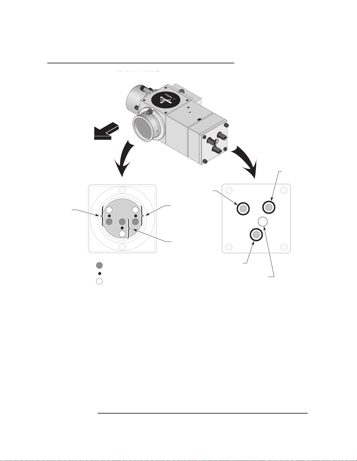
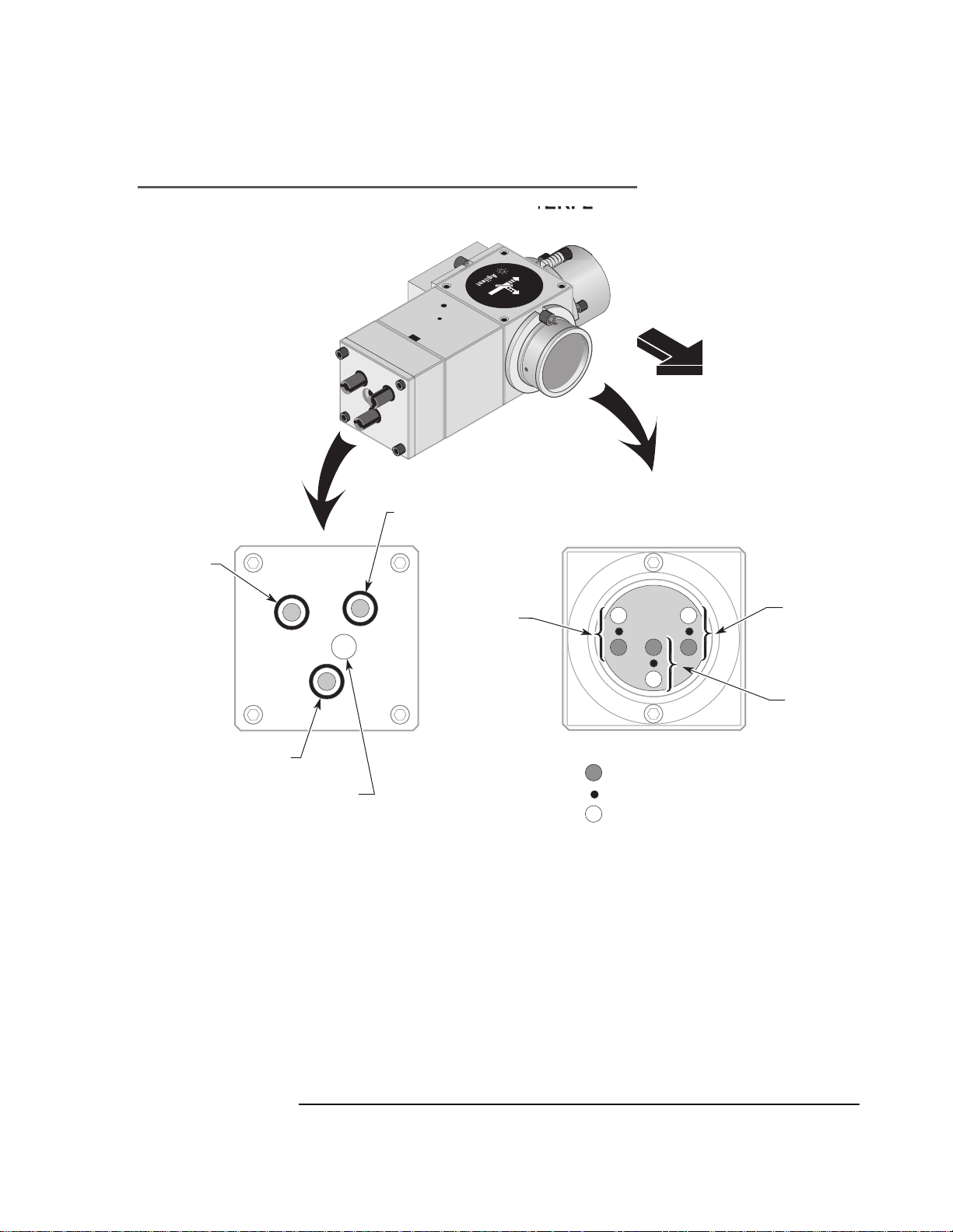
The Agilent 10737L/R Compact Three-Axis interferometers (see
figures 7O-1 through 7O-3) allow up to three measurements
(displacement, pitch, and yaw) to be made on a single axis. The
Agilent 10737L and Agilent 10737R interferometers are identical
except that the “L” bends the measurement beams to the left and the
“R” bends the beams to the right, as viewed from the incoming beam
(see figures 7O-2 and 7O-3).
These interferometers are designed to use a 3 mm diameter laser
beam, available from an Agilent 5517C-003 Laser Head.
The measurement beam parallelism inherent in the design of the
Agilent 10737L/R interferometers ensures that there is essentially no
cosine error between their three measurements and also ensures angle
accuracy for pitch and yaw measurements.
These interferometers are designed for direct attachment of
Agilent 10780F-037 Remote Receiver’s fiber-optic sensor head (one per
axis). The Agilent 10780F-037 receiver is the same as the standard
receiver, except it does not include the lens assembly that attaches to
some Agilent interferometers; in this case, the required lens assembly
is part of the Agilent 10737L/R interferometer. This simplifies user
assembly, since no optical alignment of the recei ve r is required. The
fiber-optic cables from the receivers attach directly to the axis output
apertures on the input face of t he inter feromete r. S ee fi gures 7O-2 and
7O-3.
The Agilent 10737L/R interferometers are based on the
Agilent 10706B High-Stability Plane Mirror Interferometer’s design.
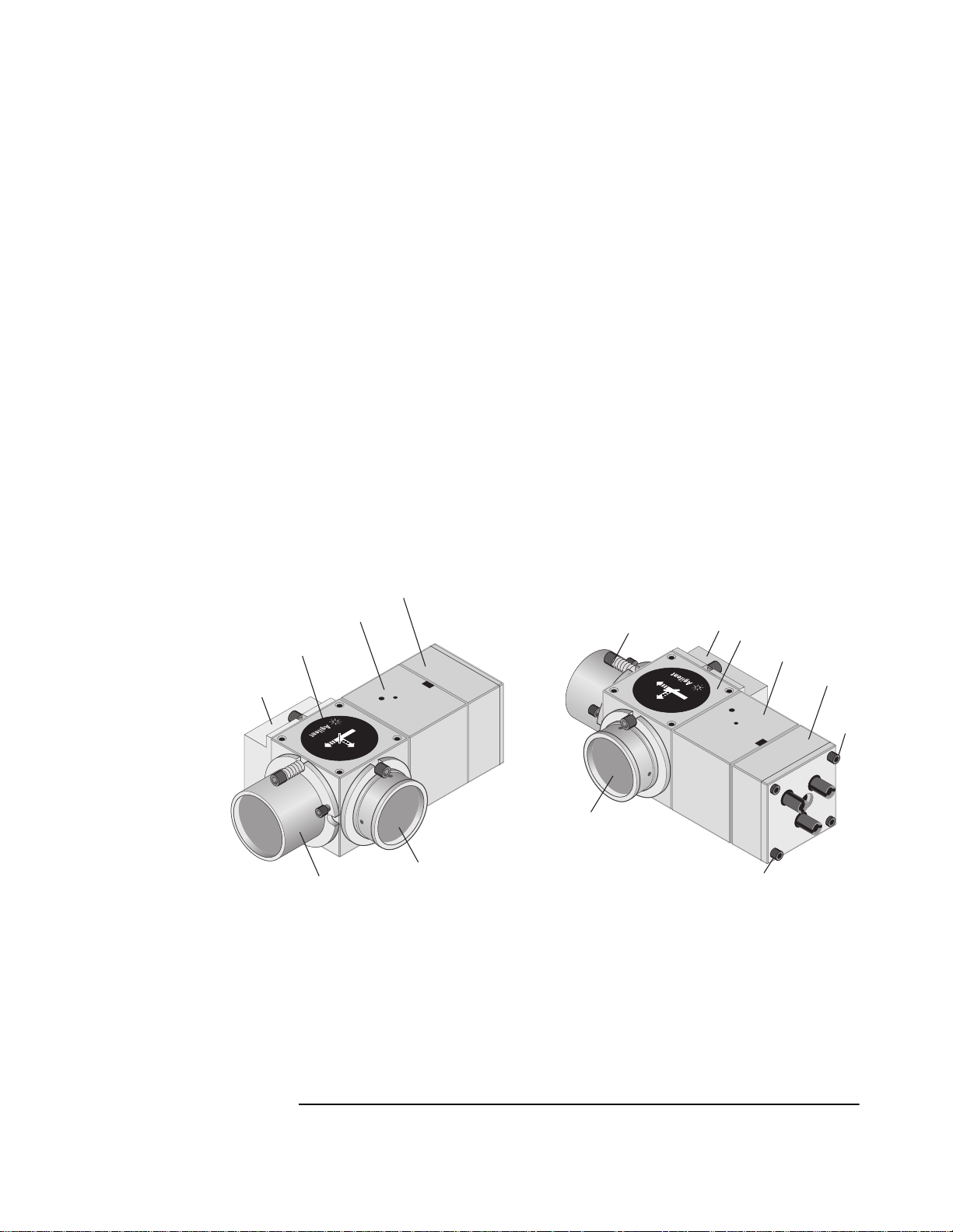
Figure 7O-1 shows two views of an Agilent 10737L interferometer. In
addition to the Agilent 10706B components, the interferometer
includes the following assemblies:
• The receiver assembly. This can be removed during alignment
using the 4-40 socket-head cap screws. The 4-40 button-head
screws hold the 0.100-inch-thick cover plate and the receiver
assembly parts in place; do not try to lo osen these screws or r emove
the plate.
• The shear plate assembly. This assembly is factory-aligned and
must not be loosened or removed.
7O-2 User’s Manual
Page 3
Chapter 7O Agilent 10737L and Agilent 10737R Compact Three-Axis
Interferometers
Description
• The corner cube assembly. This assembly is factory-aligned to
produce the required beam pattern. Do not remove the corner cube
assembly or loosen the screws holding the assembly in place.
Moving this assembly will change the output beam pattern.
1
Corner cube assembly
(Do not loosen or remove)
2
Reference mirror or high stability adapter
3
Plane mirror converter
4
Polarizing beam splitter
5
Shear plate assembly
(Do not loosen or remove)
6
Receiver assembly
7
4-40 socket-head cap screws
attaching receiver assembly
6
5
2
4
L
03
7
R
E
T
E
M
O
1
10737
1
R
0
7
3
7
L
3
-
A
X
I
S
I
N
T
E
R
R
F
E
E
T
R
E
F
M
E
O
R
R
E
F
R
E
F
R
10
1
0
E
7
T
3
7
N
I
L
S
3
I
-
X
A
3
3
2
Figure 7O-1. Agilent 10737L Compact Three-axis Interferometer
1
4
5
6
7
7
User’s Manual 7O-3
Page 4
AGILENT 10737L COMPACT THREE-AXIS INTERFEROMETER
s
#2
B
To
M
easuremen
Chapter 7O Agilent 10737L and Agilent 10737R Compact Three-Axis
Interferometers
Description
R
10737L
1
R
0
E
7
T
3
7
N
I
L
S
3
I
-
X
A
S
ee
V
iew
V
t
S
ee
iew
E
T
E
M
O
R
E
F
R
E
F
M
irro
r
A
A
O
xis
utpu
#2
t
A
xis
#1
O
utpu
t
A
x
i
A
xis
#1
= P
rimar
y m
easuremen
=
M
easuremen
= S
ec
V
iew
A
MEASUREMEN
ondar
T FACE
t Poin
t
y m
easement beam
A
xis
t beam
#3
A
O
I
npu
xis
#3
utpu
t
t for a
ll
V
INPUT FACE
A
xes
iew
B
Figure 7O-2. Agilent 10737L Compact Three-Axis Interferometer
7O-4 User’s Manual
Page 5
AGILENT 10737R COMPACT THREE-AXIS INTERFEROMETER
V
t
S
ee
iew
Chapter 7O Agilent 10737L and Agilent 10737R Compact Three-Axis
Interferometers
Description
10737R
1
0
7
3
7
R
3
-
A
X
I
S
I
N
T
E
R
R
E
F
T
E
E
R
M
F
E
O
R
To
M
easuremen
S
ee
V
iew
B
A
A
xis
#2
O
u
tpu
t
M
irro
r
A
xis
O
utpu
#1
t
A
xis
A
xis
t beam
t beam
#2
#3
A
xis
#3
O
utpu
t
I
npu
t for a
V
iew
INPUT FACE
A
xis
#1
= P
rimar
y m
easuremen
=
M
= S
V
easuremen
ec
ondar
iew
ll
A
xes
A
MEASUREMEN
t Poin
y m
easuremen
B
T FACE
t
Figure 7O-3. Agilent 10737R Compact Three-Axis Interferometer
User’s Manual 7O-5
Page 6

Chapter 7O Agilent 10737L and Agilent 10737R Compact Three-Axis
Interferometers
Description
Applications
General
The Agilent 10737L or Agilent 10737R interferometer, by making
three simultaneous distance measurements along or parallel to the
X-axis, can make these measurements:
• displacement along the X-axis
• rotation (pitch) about the Y-axis
• rotation (yaw) about the Z-axis
The angular measurements made by either of these interferometers
can be calculated by taking the arctangent of the difference between
two linear measurements involved, divided by their separation:
–()
YY’
THETA arc
-------------------tan=
D
This method for determining angle is described in more detail in the
“Electronic yaw calculation method” and “Optical yaw calculation
method” subsections under t he “Three-axis system using dis crete plane
mirror interferometers (X, Y, YAW)” section in Chapter 3, “System
Design Considerations,” of this manual.
X-Y Stage
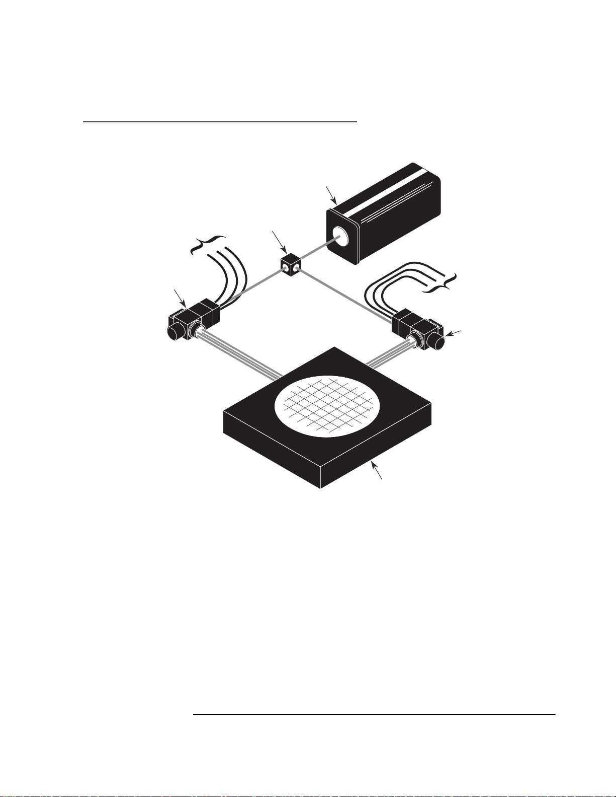
These interferometers are well suited for X-Y stage or multiaxis
applications, such as lithography equipment. Two of these
interferometers, can measure all X, Y, pitch, roll, and yaw motions of a
stage. Since only five axes are required to make all these
measurements, the sixth axis can be used as a redundant yaw
measurement (useful for mirror mapping). In these applications, the
measurement mirrors are attached to the X-Y stage.
7O-6 User’s Manual
Page 7
Chapter 7O Agilent 10737L and Agilent 10737R Compact Three-Axis
ase
ead
g
s
ete
eam
g
s
S
S
s
eter
s
Interferometers
Description
MEASUREMENT USING AGILENT 10737R/L COMPACT
THREE-AXI
Agilent 10737L
Compact Three-axi
Interferom
INTERFEROMETER
To Fiber Optics
Receivers
B
Directin
Optic
L
r H
To Fiber Optics
Receivers
A
ilent 10737R
Compact Three-axi
Interferom
r
Multiaxi
Stage
Figure 7O-4. Measurement using two Agilent 10737R interferometers
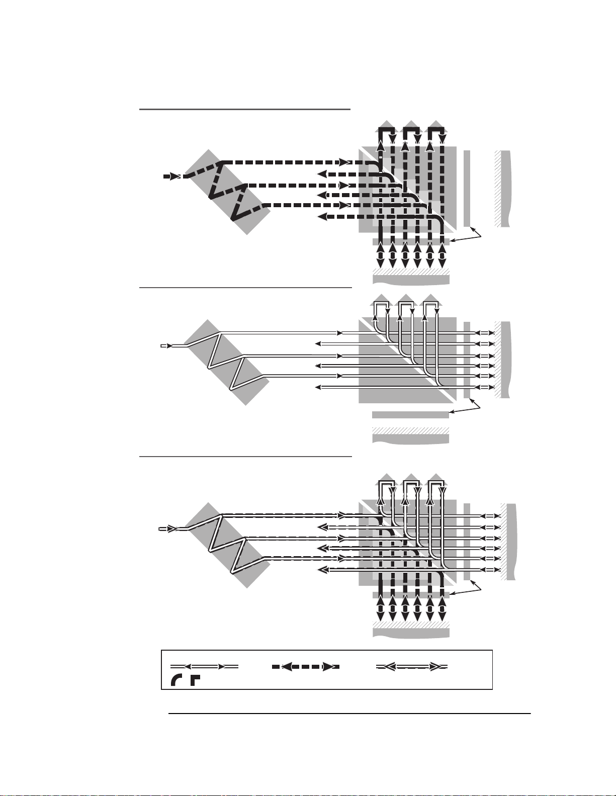
Optical Schematics
Optical schematics for these interferometers are given in Figure 7O-5.
Each interferometer functions s i milarly to three parallel
Agilent 10706B High Stability Plane Mirror interferometers with a
three-way beam splitter in front of them.
To reduce thermal drift errors, the measurement and reference beam
paths have the same op t ica l pa th len gt h in gla ss. This mini mi zes
measurement errors due to temper atur e ch anges in t he int erfer ometer .
User’s Manual 7O-7
Page 8
Chapter 7O Agilent 10737L and Agilent 10737R Compact Three-Axis
Interferometers
Description
MEASUREMENT PATH (fB)
Agilent 10737L and Agilent 10737R
Compact Three-Axis Interferometers
f
rom
ase
B
r
Axis #2
Axis #3
F
L
R
eference
M
irro
r
Axis #1 = fB±2 f
Axis #2 = fB±2 f
Axis #3 = fB±2 f
∆
∆
∆
1
2
3
NOTE: Because the Measurement
mirror may have a combination of
displacement, pitch, and yaw motions,
the Measurement Axes may have
different Df values, as shown
Axis #1
M
easuremen
M
irro
r
λ
/4
P
lat
e
t
REFERENCE PATH (fA)
Agilent 10737L and Agilent 10737R
Compact Three-Axis Interferometers
f
rom
ase
r
Axis #1 = f
Axis #2 = f
Axis #3 = f
A
A
A
A
F
L
Axis #2
Axis #3
Axis #1
M
M
R
λ
/4
easuremen
irro
r
eference
M
irro
r
P
lat
e
t
COMPOSITE (fA) and (fB)
Agilent 10737L and Agilent 10737R
Compact Three-Axis Interferometers
f
F
rom
L
ase
B
r
Axis #1 = fB±2 f
Axis #2 = fB±2 f
Axis #3 = fB±2 f
∆
∆
Axis #2
Axis #3
f
A
1,
f
∆
A
2,
f
A
3,
Axis #1
R
eference
M
irro
λ
/4
P
lat
r
e
M
LEGE
=
f
A
=
Rounded corners are used to help you trace paths.
ND
easuremen
M
irro
=
f
B
=
f
a
A
r
nd f
t
B
Figure 7O-5. Agilent 10737L/R Compact Three-Axis interferometers — beam paths
7O-8 User’s Manual
Page 9

Chapter 7O Agilent 10737L and Agilent 10737R Compact Three-Axis
Interferometers
Special Considerations
Special Considerations
Laser beam power consideration
When working with an application that requires use of a separate
beam splitter, make sure that you provide enough laser beam power to
any multia x i s i nt e rferometer so all receivers connected to it receive
adequate light power. This will help ensure that each measurement
receiver in the system receives the optimum signal strength in the
intended application.
Orientation
Note that although illustrations may show an interferometer in one
orientation, you may orient the unit as required by your measurement
application—vertically, horizontally, or ups ide-down.
User’s Manual 7O-9
Page 10

Chapter 7O Agilent 10737L and Agilent 10737R Compact Three-Axis
ete
e
ottom of
ete
as sho
n
S:
s:
easurement Point
eam
cates
P
m
(
)
(
)
m
(
)
m
(
)
(
)
m
(
)
See
1
S
2
t
s No.3
t
r
m
(
)
S
m
Interferometers
Special Considerations
AGILENT 10737L THREE-AXIS INTERFEROMETER
B
interferom
wn i
specification
drawing
GENERAL NOTE
1. For Each Axi
2. Drawing not to scale.
14.38 mm
0.566
7.19 mm
MP1
0.283
See Note 1
7.19 m
0.283
r
MP3
ee Notes 1 &
econdary Measurement bea
MP = M
Darker B
Indi
rimary Measurement bea
10.11 m
0.39
68.92
(2.71)
Note
24.49 m
20.90 mm
0.83
Interferom
Input Fac
0.964
17.3 m
0.68
Measurement Mirror
r
Axis No.1
Outpu
Axis No.2
Output
Axi
Outpu
Laser Beam turns left
(viewed from top).
R
E
T
E
M
O
R
E
F
R
E
F
R
E
T
N
I
10737L
S
I
X
A
-
3
L
7
3
7
1
0
Input fo
all axes
FROM
LASER
HEAD
From
Laser Head
Figure 7O-6A. Agilent 10737L Interferometer — beam patterns
7O-10 User’s Manual
Page 11

Chapter 7O Agilent 10737L and Agilent 10737R Compact Three-Axis
R
ete
p
e
S
1
m
(
)
m
(
)
m
(
)
m
(
)
m
(
)
m
(
)
s No.2
s No.3
t
(
)
o
s:
easurement Point
eam
cates
P
m
S
m
Interferometers
Special Considerations
AGILENT 10737R THREE-AXIS INTERFEROMETE
Input for
all axes
Axis No.1
Output
FROM
LASER
HEAD
Axi
Output
Axi
Outpu
GENERAL NOTES:
1. F
r Each Axi
econdary Measurement bea
MP = M
Darker B
Indi
rimary Measurement bea
2. Drawing not to scale.
Interferom
In
ut Fac
24.49 m
17.3 mm
0.68
ee Note
0.964
r
68.92
(2.71)
MP2
20.90 m
0.83
10.11 m
0.39
14.38 m
0.566
7.19 m
0.283
MP1
See Note 1
7.19 m
0.283
MP3
See
Notes 1 & 2
Laser Beam turns right
(viewed from top).
0
1
7
3
7
R
3
-
A
X
I
S
I
N
T
10737R
E
R
F
E
R
F
E
R
O
M
E
T
E
R
Bottom of
interferometer
as shown in
specification
drawing
Measurement Mirror
From
Laser Head
Figure 7O-6B. Agilent 10737R Interferometer—beam patterns
User’s Manual 7O-11
Page 12

Chapter 7O Agilent 10737L and Agilent 10737R Compact Three-Axis
Interferometers
Mounting
Mounting
Adjustable mounts
The Agilent 10711A Adjustable Mount provides a convenient means of
mounting, aligning, and securely locking an Agilent 10737L or
Agilent 10737R interferometer in position. Since the mount allows
some tilt and yaw adjust me n t , th e nee d for cu st o m fi xt u rin g is
minimized. The mount allows the interferometer to be rotate d about its
physical centerline, simplifying installation. Note however, that since
the input aperture is no t ce n t ered on the inpu t face, some tr a n sl a tion
of the interferometer or beam delivery opt ics may be required when the
interferometer is rotated.
Fasteners
The Agilent 10737L/R interferometers are supplied with English
mounting hardware, which is required to fasten it to its adjustable
mount.
7O-12 User’s Manual
Page 13

Chapter 7O Agilent 10737L and Agilent 10737R Compact Three-Axis
Interferometers
Installation and Alignment
Installation and Alignment
Summary
The installation and alignment procedure has two major parts:
• Planning and setting up the laser beam path(s)
• Installing and aligning the interferometer(s).
Objectives of the installation and alignment procedure are:
1. Minimizing cosine error.
2. Maximizing signal strength at the receivers.
3. Ensuring a symmetrical range of rotation about the zero angle
point.
General
Refer to the Agilent 10706A interferometer “Installation” information
in subchapter 7C of this manual.
Tools and Equipment Required or Recommended
Table 7O-1 lists and describes the tools and equipment needed to
install and align the Agilent 10737L and 10737R interferometers.
User’s Manual 7O-13
Page 14

Chapter 7O Agilent 10737L and Agilent 10737R Compact Three-Axis
Interferometers
Installation and Alignment
Table 7O-1. Tools and Equipment Required or Recommended
Item and Description Mfr. Part Number (Mfr =
Agilent unless otherwise
indicated)
Penta prism or similar prism that bends
light exactly 90 degrees
True square L.S. Starret, Athol, Mass. Recommended, but not required.
Washer, lock, 0.115 in id, 0.270 in od,
internal tooth; qty = 6
Screw, cap, 4-40, 0.500 in lg, hex trim
head 0.187 in (3/16 in) across flats; qty =
2
Screw, machine, 4-40, 1.75 in lg, pan
head, pozidriv; qty = 6
Screw, socket head cap, 4-40, 0.250 in
lg, hex recess 0.094 in (3/32 in) across
flats; qty = 2
Prisms of this type are available
from scientific or optical supply
shops
2190-0004 Supplied with Agilent 10737L/R
2940-0269 Supplied with Agilent 10737L/R
2200-0127 Supplied with Agilent 10737L/R
3030-0253 Supplied with Agilent 10737L/R
Comment, Note, etc.
Recommended, but not required.
For setting up right angles in the
beam paths from the laser head to the
interferometers.
An Agilent 10777A Optical Square
may be used.
For setting up beam paths parallel to
or perpendicular to machine surfaces
that are parallel to or perpendicular to
the stage mirrors.
Interferometer.
Interferometer.
Interferometer.
Interferometer.
Screw, socket head cap, 2-56, 0.187 in
lg, 0.064 in radius oval point, hex recess;
qty = 2
Hex key, 5/64 in (0.078–in) 8710-0865 Supplied with Agilent 10737L/R
Hex key, 3/32-in (0.094 in) 8710-0896 Supplied with Agilent 10737L/R
Wrench, 3/16-in open-end 8710-1740 Supplied with Agilent 10737L/R
3030-0983 Supplied with Agilent 10737L/R
Interferometer.
Interferometer.
Interferometer.
Interferometer.
Used to secure the Agilent 10711A
Adjustable Mount.
Alignment Aid 10706-60001 Supplied with the Agilent 10737L/R
Interferometer.
See Figure 7O-7 for illustration.
Alignment Aid 10706-60202 Supplied with the Agilent 10737L/R
Interferometer.
See Figure 7O-7 for illustration.
7O-14 User’s Manual
Page 15

Chapter 7O Agilent 10737L and Agilent 10737R Compact Three-Axis
Interferometers
Installation and Alignment
Alignment aid (Agilent Part Number 10706-60001) is the same as one
used on the Agilent 10706B Plane Mirror Interferometer. Refer to the
“Alignment aids” section for the Agilent 10706B Plane Mirror
Interferometer, in subchapter 7C of this manual for a further
discussion of its use.
Alignment aid (Agilent Part Number 10706-60202), shown in
Figure 7O-7, facilitates autoreflection alignment for the high stability
adapter to achieve minimal thermal drift. It contains a quarter-wave
plate which allows the reference beam to return to the laser head
without offset. Figure 7O-10 illustrates how the aid is positioned
between the beam splitter and the high stability adapter during
alignment.
Alignment Aid
Insert between Beam Splitter
and High Stability reflector
during autoreflection.
Caution: Fragile
RGET
TA
REMOVE
ER ALIGNING
AFT
logies
Agilent Techno
Alignment Aid
P/N 10706-60001
P/N 10706-60202
Alignment Aid
P/N 10706-60202
Figure 7O-7. Agilent 10737L/R interferometers—alignment aids
User’s Manual 7O-15
Page 16

Chapter 7O Agilent 10737L and Agilent 10737R Compact Three-Axis
Interferometers
Procedure
Procedure
Planning the measurement setup
Determine the general plan for your measurement. Examples of
measurement setups are given throughout this manual. Particularly,
your plan should address:
1. Which axes you want to measure, and what measurements you
want to make,
2. Where the interferometers will be positioned with respect to the
stage mirrors,
3. Where the laser head will be positioned and how the laser beam
will be delivered to the interferometers, and
4. Making sure you will have enough laser po wer to drive all r eceivers
in your measurement system.
Good practice defines the plan e and direc tion of all beam paths against
machined surfaces known to be parallel or perpendicular to the stage
plane.
You may need to provide special mounting arrangements for the laser
head and the optics in order to place the measurement beams where
you want them on the stage mirrors.
Initial installation and setup
1 Install the laser head, the beam-steering opti cs, and the bea m-splitting
optics in their general locations, as specified in your plan. The
interferometer(s) will be installed after the beam paths have been
established as described below.
2 Turn on power to the las er head and select the laser head’s small
output aperture.
3 Refer to Chapter 4, “System Installation and Alignment,” in this
manual, beginning with the “Alignment princip les” section, for
additional information about aligning your measurement setup.
7O-16 User’s Manual
Page 17

Chapter 7O Agilent 10737L and Agilent 10737R Compact Three-Axis
Interferometers
Procedure
Installing and aligning an interferometer
CAUTION In performing the procedure below, perform only the removal,
disassembly or assembly steps described. Do not remove or take apart
anything you are not instructed to. Do not touch any glass surface or
allow it to be scratched, dirtied or otherwise harmed.
CAUTION Do not touch any glass surface of any optic. For cleaning instructions,
see Chapter 10, “Maintenance,” in this manual.
Perform this procedure for each interferometer in your measurement
system.
This procedure assumes that the laser head and all optics except the
interferometer(s) have been installed an d that the appropriate beam
path(s) to the stage mirror(s) have been established as described in
Chapter 4, “System Installation and Alignment,” of this manual.
The procedure has these major parts:
1. Removing the receiver assembly
2. Removing the high stability adapter (reference mirror)
3. Aligning the measurement beam path
4. Aligning the reference beam path
5. Comparing beam path alignments
Removing the receiver assembly
To remove the receiver assembly, refer to figures 7O-1 and 7O-8.
1 Use the 5/64-inch hex key to remove the two cap screws that hold the
receiver assembly to the interferometer. Set the screws in a clean, safe
place where they will not be lost.
2 Remove the receiver assembly from the i nterferometer. Set the receiver
assembly in a clean, safe place.
User’s Manual 7O-17
Page 18

Chapter 7O Agilent 10737L and Agilent 10737R Compact Three-Axis
107 37L
Interferometers
Procedure
Removing the high stability adapter (reference mirror)
To remove the high stability adapter, refer to figures 7O-1 and 7O-8,
and:
1 Use the 5/64-inch hex key to rem ov e the two cap screws with springs
that hold the high stability adapter (reference mirror) to the
interferometer. Set th e screws in a cle an, safe place wher e they will not
be lost.
2 Remove the high stability adapt er (reference mirror) from the
interferometer. Set the high stability adapt er in a clean, safe place.
Input
Beam
1
10737L
R
E
T
E
0
7
3
7
L
3
-
A
X
I
S
I
N
T
E
R
F
E
R
F
M
E
O
R
Center on One
Measurement Beam
Alignment Aid 10706-60001
Measurement
Beam
Figure 7O-8. Agilent 10737L Compact Three-Axis Interferometer with
Agilent 10706-60001 Alignment Aid
NOTE From here on, this procedure assumes that the interferometer is
installed on an Agilent adjustable mount.
7O-18 User’s Manual
Page 19

Chapter 7O Agilent 10737L and Agilent 10737R Compact Three-Axis
Interferometers
Procedure
Aligning the measurement beam path
1 Remove the receiver assembly and high stability adapter, as describ ed
in the respective procedures, above.
2 Install the interferometer so the beam from the laser source ente rs its
input aperture and is normal to its input face.
3 Set the alignment aid (Agilent Part Number 10706-60001) on the
interferometer’s Measurement beam aperture as shown in
Figure 7O-8.
With the alignment aid installed, the beam will be reflected off the
stage mirror back to the laser head.
4 Set the laser head to the small aperture.
5 Roll and yaw the interferometer until the autoreflected beam is
centered on the small aperture of the laser.
6 Select the laser head’s large output aperture and translate the
interferometer horizontally until the input beam is centered on the
interferometer’s input aper ture.
A piece of translucent tape over the interf erometer’s input aperture
will make the input beam visible. This procedure assumes that the
vertical height of the beam was set before the interferomete r was
installed, (see the “Initial installation and setup” procedure);
alternatively, fixturing for a ver tical ad justment fo r the int erf erometer
may be used.
7 Select the laser head’s small output aperture and check that the beam
is still autoreflecting.
8 Repeat steps 3 through 7 until the beam is both autoreflecting and
centered on the interferometer's input aperture.
9 Tighten all mount adjustment screws.
10 Remove the alignment aid.
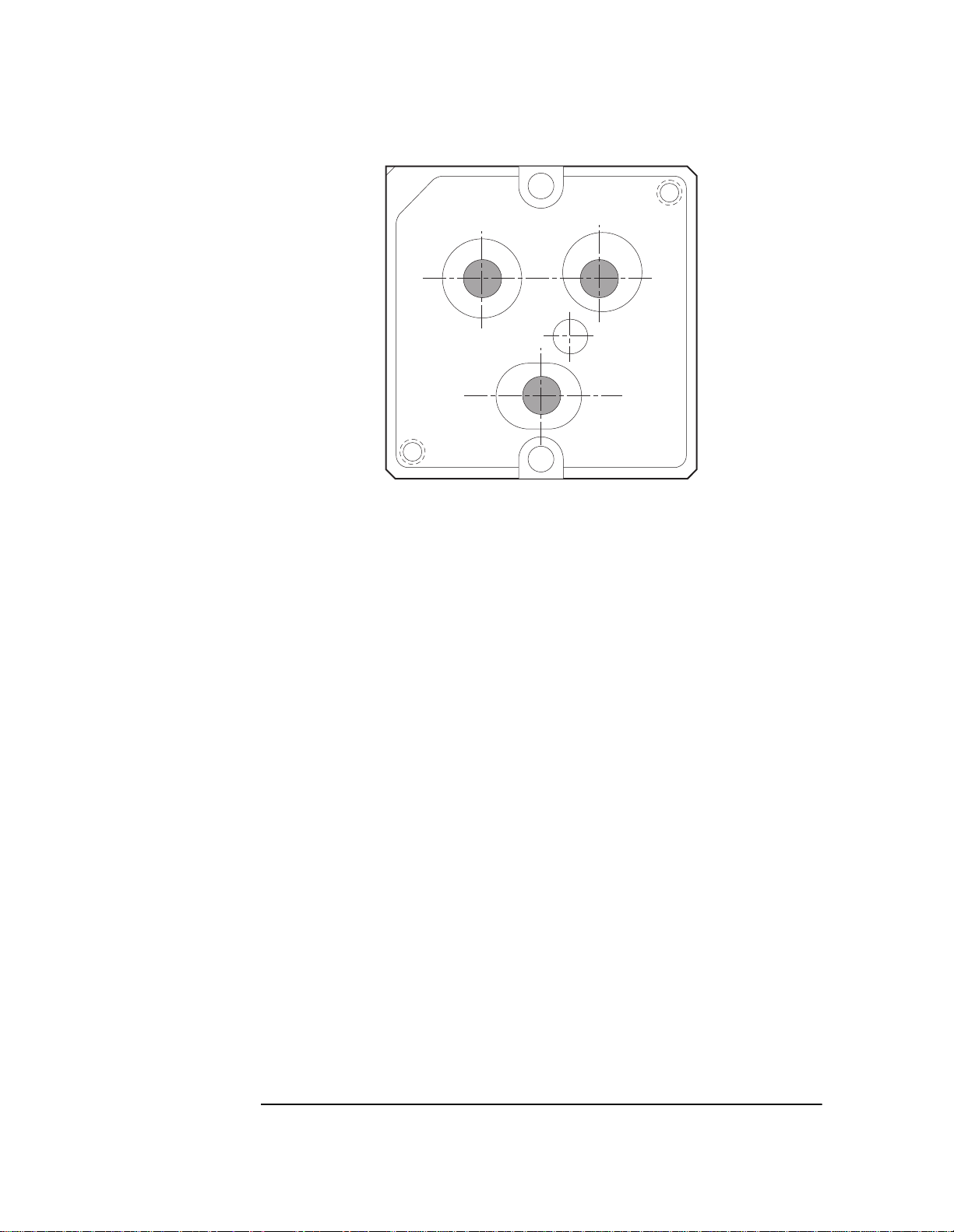
11 Check the position of the beams in the interferometer’s output
apertures (see Figure 7O-9).
Once again, translucent tape is helpful for viewing the beams in the
apertures. If any beam clipping occurs, or if the beams are far off from
the desired location, check for obstructions and recheck the alignment
(by performing steps 3 through 7 above).
User’s Manual 7O-19
Page 20
Chapter 7O Agilent 10737L and Agilent 10737R Compact Three-Axis
Interferometers
Procedure
Figure 7O-9. Agilent 10737L Compact Three-Axis Interferometer —
return beam pattern
12 Install the receiver assembly.
To do this, reverse the “Removing the receiver ass embly” procedure,
above.
13 Plug in the fiber-optic cables.
14 Adjust each receiver’s gain by turning its gain adjustment screw to
cause the receiver’s LED to light, then reduce the gain until the LED
just turns off. For more information, see Agilent 10780F instructions in
Chapter 8, “Receivers,” of this manual.
7O-20 User’s Manual
Page 21

Chapter 7O Agilent 10737L and Agilent 10737R Compact Three-Axis
Interferometers
Procedure
Aligning the reference beam path
NOTE The measurement path must be aligned and the laser beam centered
on the input aperture before aligning the reference mirror.
1 Remove the receiver ass embly and the plane mirror converter (see
figures 7O-1 and 7O-4), and set aside on a clean surface. Do not touch
any glass surface of any optic.
7L
R
E
T
E
M
O
R
E
F
R
E
F
R
3
107
1
E
T
N
I
0
7
3
7
L
S
3
I
-
X
A
Alignment Aid
10706-60202
Input
Beam
Figure 7O-10. Agilent 10737L Compact Three-Axis Interferometer
with 10706-60202 Alignment Aid
2 Install the refer ence mirror assembly (see figures 7O-1 and 7O-4).
The 4-40 screws on springs hold the mirror in place. The four 2-56
screws tilt the mirror for alignment. Back off the 2-56 screws so the
mirror housing is flush with the interferometer. Tighten the
4-40 screws to compress the springs completely and then back off
approximately 1-1/2 turns.
3 Place the 10706-60202 alignment aid between the beam spl itting cube
and the reference mirror (see Figure 7O-10).
4 Block the beams going to the stage mirror.
5 Set the laser to the small aperture.
User’s Manual 7O-21
Page 22

Chapter 7O Agilent 10737L and Agilent 10737R Compact Three-Axis
Interferometers
Procedure
6 Tilt the reference mirror by adjusting the 2-56 screws until the beam
from the reference mirror autoreflects back to the center of the laser
small aperture.
7 Remove the alignment aid.
8 Check the position of the beams in the interferometer’s output
apertures (see Figure 7O-9).
Once again, translucent tape is helpful for viewing the beams in the
apertures. If any beam clipping occurs, or if the beams are far off from
the desired location, check for obstructions and recheck the alignment
(by performing steps 6 through 10 above).
9 Install the receiver assembly.
To do this, reverse the “Removing the receiver ass embly” procedure,
above.
10 Plug in the fiber-optic cables.
11 Adjust each receiver’s gain by turning its gain adjustment screw to
cause the receiver’s LED to light, then reduce the gain until the LED
just turns off. For more information, see Agilent 10780F instructions in
Chapter, 8, “Receivers,” of this manual.
12 Unblock the stage mirror beams.
Comparing beam path alignments
1 Remove the receiv er assembly.
2 Look for any lac k of overlap between the reference and measurement
return beams, translucent tape will help. If beams do not overlap,
check reference mirror alignment.
Note that if you must realign the measurement mirror, you will also
have to realign the reference mirror.
3 Install the receiver assembly and make sure all screws are tight.
7O-22 User’s Manual
Page 23

Chapter 7O Agilent 10737L and Agilent 10737R Compact Three-Axis
Interferometers
Operation
Operation
Measurements
For an interferometer setup to measure distances along the X-axis,
measurements of displacement, pitch, and yaw are derived as
described below. These computations are done via software on the
system controller or computer .
Displacement
For the Agilent 10737L/R interferometer, displacement along the
X-axis can be measured as the average of the data returned from
measurement axis #1 and measurement axis #2.
Displacement
measurement axis #1 + measurement axis #2
------------- ------------- ------------ ----------- ------------- ------------- ------------ ------------- -----------=
2
Pitch
For the Agilent 10737L/R interferometer, pitch (rotation about the Y
axis) can be measured using data returned f rom all three measurement
axes, and the vertical offset between the common centerline of
measurement axes #1 and #2 and the centerline of measurement
axis #3 (7.19 mm, or 0.283 inch).
Displacement measurement axis #3 –
Pitch
------------- ------------ ------------- ----------- ------------- ------------ ------------- -----------
7.19 mm or 2.83inc h
radian=
Yaw
For the Agilent 10737L/R interferometer, yaw (rotation about the
Z axis) can be measured as the difference between the data returned
from measurement axis #1 and measurement axis #2, divided by the
distance between them (14.38 mm, or 0.566 inch).
measurement axis#1measurement axis #3 –
Yaw
----------- ------------- ------------- ---------- ------------- ------------- ------------- ------------ ----------- ---------
14.38 mm or 0.5666 inch
radian=
Error
The deadpath distance for an Agilent 10737L/R interferometer is the
distance between the interferometer’s measurement face and the
measurement mirror, at the measurement “zero” position. This is the
same as for the Agilent 10706B interferometer, on which it is based.
User’s Manual 7O-23
Page 24
Chapter 7O Agilent 10737L and Agilent 10737R Compact Three-Axis
Interferometers
Specifications and Characteristics
Specifications and Characteristics
Specifications describe the device’s warranted performance.
Supplemental characteristics (indicated by TYPICAL or NOMINAL)
are intended to provide non-warranted p erformance information useful
in applying the device.
Plane mirror systems have a fundamental optical resolution of one
quarter wavelength (0.158 micron, 6.23 microinches).
Using electronic resolution extension, the sys tem resolution is
increased significantly. Depending on the system, an additio nal
resolution extension factor of 32 (for Agilent 10885A and 10895A) or
256 (for Agilent 10897B and 10898A) is usually available.
Interferometer Fundamental Optical
Resolution
Agilent 10737L or Agilent 10737R λ/4 (158.2 nm, 6.2 µin) See specifications on
System Resolution (see
NOTE)
following page.
7O-24 User’s Manual
Page 25

Chapter 7O Agilent 10737L and Agilent 10737R Compact Three-Axis
Interferometers
Specifications and Characteristics
Agilent 10737L/R Compact Three-Axis Interferometer Specifications
Linear Resolution: 5 nm (using Agilent 10885A, or Agilent 10895A electronics)
0.6 nm (using Agilent 10897A, or Agilent 10898A electronics)
Yaw Resolution: 0.35 µrad (0.07 arc-sec) (using Agilent 10885A, or Agilent 10895A electronics)
0.04 µrad (0.01 arc-sec) (using Agilent 10897A, or Agilent 10898A electronics)
Pitch and Roll Resolution: 0.7 µrad (0.14 arc-sec) (using Agilent 10885A, or Agilent 10895A electronics)
0.1 µrad (0.02 arc-sec) (using Agilent 10897A, or Agilent 10898A electronics)
*
Yaw Ra ng e
Pitch and Roll Range: ±0.44 mrad (±1.5 arc-min)
Linear Range: 10 m (33 ft) total for all three axes.
Operating Temperature: 0–40 °C (17–23 °C to ensure system non-linearity specification)
Thermal Drift Coefficient: Same as Agilent 10706B
Weight: 490 g (18 oz)
Dimensions: see Figure 7O-11 on the next page
Materials Used: Housing: stainless steel and aluminum
Installation: Uses 3-mm beam available from Agilen 5517C-003. Requires three
Measurement (Plane) Mirror
Recommendations:
Optical Surface Quality: 60-40 per Mil 0-13830
: ±0.44 mrad (±1.5 arc-min)
Optics: optical grade glass
Adhesives: vacuum grade, cyanoacrylate polarizer material
Receiver inserts: urethane foam, acetal, 15% glass fill polyester
Agilent 10780F-037 Remote Receivers. Compatible with Agilent 10711A
Adjustable Mount.
Reflectance: 98% at 633 nm at normal incidence
Flatness: Flatness deviations will appear as measurement errors when the mirror
is scanned perpendicular to the beam. Recommended range 1/4 (0.16 µm or 6 µin)
to 1/20 (0.03 µm or 1.2 µin) dependent on accuracy requirements.
* At a distance of 300 mm, maximum measurement mirror angle due to all components (i.e., yaw and pitch or yaw
and roll) between the measurement mirror and the interferometer. A six-axis system is assumed.
User’s Manual 7O-25
Page 26

Chapter 7O Agilent 10737L and Agilent 10737R Compact Three-Axis
ce
d
6-32 U
p
de.
Connectors
g
7
eceivers
t
3
m
(
)
3
m
(
)
3.0 mm
(
)
aser
or
(
)
8
m
(
)
m
(
)
(
)
38
m
(
)
(
)
m
(
)
m
(
)
6
m
(
)
m
(
)
Interferometers
Specifications and Characteristics
2 m
1.26
2 m
1.26
4x Drilled For Clearan
of 4-40 Screw and tappe
NC-2B
.250 dee
4x this side and 4x far si
7.19 mm
0.283
.2 m
1.50
7.19 m
0.283
7.19 m
0.283
10703L
R
-
To Plane Mirr
125 mm
1
0
7
3
7
L
3
4.92
66 mm
7.19 mm
0.283
2 m
3.22
(2.6)
3 x Fiber-Optic
for A
R
0.12
22.63 mm
0.891
17.3 m
0.68
ilent 10780F-03
From L
4.1 m
(2.53)
Inpu
Aperture
17.3 m
0.68
Agilent 10737L interferometer is shown; Agilent 10737R interferometer dimensions are similar.
Figure 7O-11. Agilent 10737L/R Compact Three-Axis Interferometer — dimensions
Product specifications and descriptions in this
document subject to change without notice.
Copyright (C) 2002 Agilent Technologies
Printed in U.S.A. 07/02
This is a chapter from the manual titled:
Laser and Optics User's Manual
For complete manual, order:
Paper version: p/n 05517-90045
CD version: p/n 05517-90063
This chapter is p/n 05517-90122
7O-26 User’s Manual
 Loading...