

Page 1
Agilent 4291B
RF
Impedance/Material
Analyzer
Quick
SERIAL
This
JP1KE
important
Appendix
NUMBERS
manual
and
applies
above
information
A
of this
Start Guide
directly
,
or
whose
about
to
instruments
rmware is
serial
numbers
with serial
version 1.xx.
,
manual.
number prex
For
read \Serial
additional
Number" in
Agilent Part No. 04291-90031
Printed in JAPAN March 2001
Page 2
Notice
The
information
without
This
notice
document
copyright.
photocopied,
the
prior
written
contained
.
contains
All
rights
reproduced,
consent
in
proprietary
are
reserved.
or
of
this
document
No
translated
the
Agilent
is
information
part
of this
to
another
Technologies
subject to
that
is
protected by
document may
language
.
change
be
without
Agilent
Component
1-3-2,
Hyogo
MS-DOS
APC-7
R
T
echnologies
T
Murotani,
,
651-2241
R
is
a
U
is a
U.S.
Japan, Ltd.
est
PGU-Kobe
Nishi-ku,
Kobe-shi,
Japan
.S.
registered
trademark
registered trademark
of
of
Bunker
Microsoft
Ramo
Corporation.
Corporation.
c
Copyright 1997, 1998, 1999, 2001 Agilent Technologies Japan, Ltd.
Page 3
Manual
History
Printing
The
manual printing
edition.
(Minor
cause
The printing
corrections
the date
extensive
date and
date changes
and
updates that
to change
.) The
technical changes
part number
when a
indicate its
new edition
are incorporated
manual part
are incorporated.
current
is printed.
at reprint
number changes
do not
when
Safety
Summary
Note
Note
December
December
December
March
The
phases
comply
in
this
In
addition
intended
The
failure
4291B
DEGREE
LEDs
CLASS
2001
following general
of operation,
with
manual
use
A
gilent
to
comply
comply
2
in
4291B
1
LED
1997
:
1998
:
1999
:
:
::
::
these
precautions
may
it
violates
of
the
T
echnologies
with
with
in
IEC1010-1.
are
Class
PRODUCT
::
::
::
:
:
:
:
First
::
::
::
:
:
Second
::
:
:
:
:
:
:
:
:
Third
:
:
:
:
:
:
:
:
F
ourth
safety precautions
service
,
and
or
impair
safety
the
protection
standards
instrument.
assumes
these
requirements
INST
ALLA
TION
4291B
1
are
in
accordance
Edition
Edition
Edition
Edition
(part
(part
(part
(part
must
repair
of
this
with specic
provided
of
design,
no
liability
.
CA
TEGORY
INDOOR
with
number:
number:
number:
number:
be
observed
instrument.
W
ARNINGS
by
the
manufacture
for the
USE
II
and
product.
customer's
IEC825-1.
04291-90021)
04291-90031)
04291-90031)
04291-90031)
during
F
ailure
elsewhere
equipment.
,
and
POLLUTION
all
to
Ground
The
Instrument
DO
NOT
Explosive
Operate
In
Atmosphere
Keep Away From Live
Circuits
An
T
o
avoid
electric
must
be connected
cable
with earth
Do
not
operate
fumes
.
Operation
constitutes
Operating personnel must not remove
replacement and internal adjustments must be
maintenance personnel. Do not replace components with
cable connected. Under certain conditions
exist even with the power cable removed. T
a
denite
shock
to a
blade.
the
instrument
of any
safety hazard.
hazard,
safety earth
the
instrument chassis
ground
in the
presence of
electrical instrument
instrument covers
and cabinet
by
the
supplied
power
ammable gasses
in such
an environment
. Component
made by qualied
the power
, dangerous voltages
o avoid injuries
,always
disconnect power and discharge circuits before touching them.
or
may
iii
Page 4
DO NOT
A
Service Or
djust Alone
Do
not attempt
capable
internal service
of rendering
rst aid
or adjustment
and resuscitation,
unless another
is present.
person,
DO
NOT Substitute
P
arts
Dangerous
W
arning
Safety Symbols
Or Modify
Instrument
Procedure
W
arnings
Because
install
instrument.
Service
of
the
substitute
Return
Oce
for
danger
maintained.
W
arnings
procedures
warnings
Dangerous
,
such
throughout
must
be
voltages
instrument. Use
adjusting
General
are
listed
this
instrument.
denitions of
below
.
of
introducing
parts
or
perform unauthorized
the
instrument
service
as
and
the
example below
this
followed.
,
capable
extreme
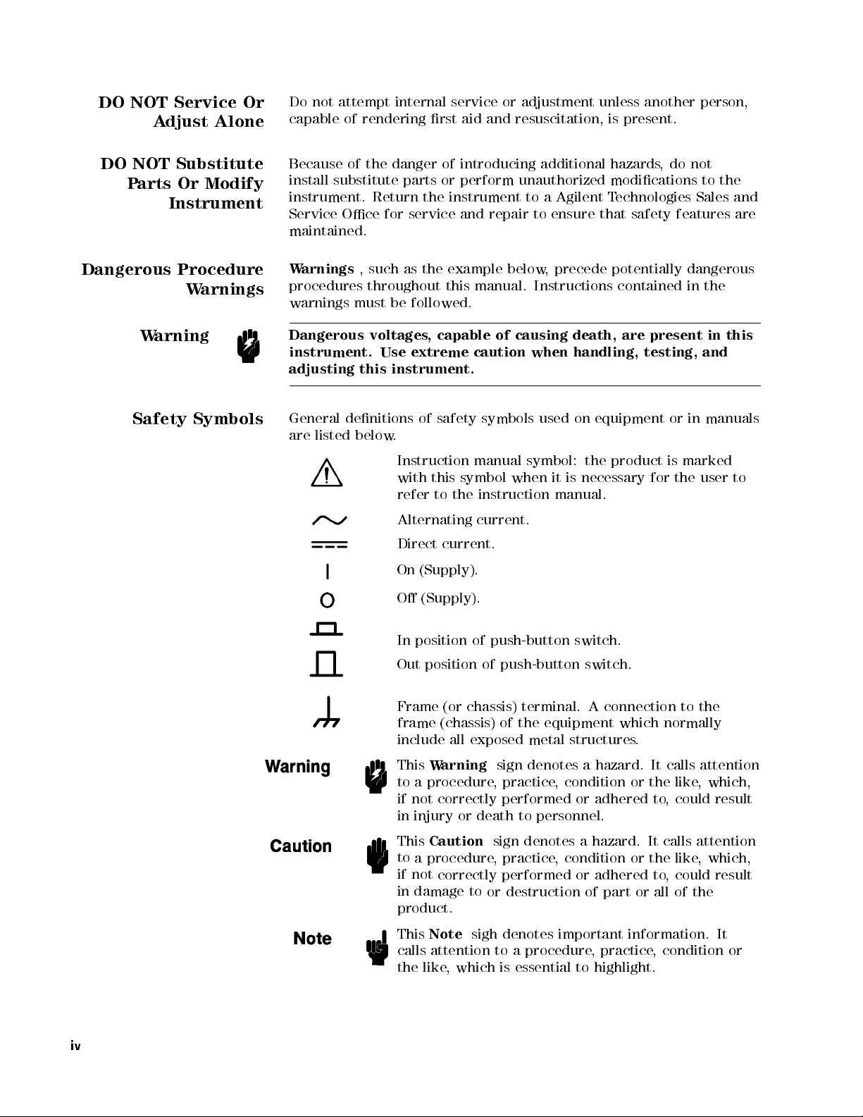
safety symbols
Instruction
with
this
symbol
refer
to
the
Alternating
Direct
current.
On (Supply).
to
repair
manual.
of
causing
caution
manual
symbol:
when
instruction
current.
additional
a
Agilent T
to ensure
, precede
Instructions
death,
when
handling,
used on
equipment
the
it
is
necessary
manual.
hazards
,do
not
modications to
echnologies Sales
that safety
features are
potentially dangerous
contained
are
product
in the
present
testing,
or
is
marked
for
the
in
and
in
manuals
user
the
and
this
to
O
(Supply).
In
position
Out
position
Frame
frame
include
This
Warning
to a procedure
if not correctly performed or adhered to
of
of
(or
chassis)
(chassis)
all
exposed
push-button
push-button
terminal.
of
the
metal
sign
denotes a hazard. It calls attention
, practice
switch.
switch.
A
connection
equipment
structures
which
.
normally
, condition or the like
, could result
to
the
, which,
in injury or death to personnel.
This
Caution
to
a procedure
if not
correctly performed or adhered to
in damage to
sign denotes a hazard. It calls attention
, practice
, condition or the like
, which,
, could result
or destruction of part or all of the
product.
This
Note
sigh denotes important information. It
calls attention to a procedure, practice, condition or
the like, which is essential to highlight.
iv
Page 5

Axed
use
electrostatic
to product
anti-static handling
discharge damage
containing static
procedures to
to component.
sensitive devices
prevent
v
Page 6
Typeface
Conventions
Bold
Italics
Boldface type
F
or example:
Italic type
of
manuals and
Italic
when
place
copy
to
type a
a
le such
is used
type is
a name
of
the
lename
space,
as
is used
icons
when a
are
symbols.
for emphasis
other publications
also used
or a
words in
means
and
file1
for keyboard
variable must
italics.
to type
then
.
to
term is
and for
For
the
type
dened.
titles
.
entries
be typed
example:
word
copy
the
name
in
,
of
Computer
4
HARDKEYS
N
N
N
N
N
N
N
N
N
N
N
N
N
N
N
N
N
N
NN
SOFTKEYS
Computer font
and
messages.
5
NN
N
N
N
N
Labeled keys
are
enclosed in
Softkeys
enclosed
on
located
N
N
N
N
N
.
in
is used
the
5
.
4
to
the right
for on-screen
instrument
of
front
the
prompts
panel
LCD
are
vi
Page 7
Certication
Warranty
Agilent
specications
T
echnologies
traceable
T
echnology,
facility
Organization
This
defects
the
listed
be
T
echnologies
prove
For
Technologies
at the
further
to the
to the
,or
to the
members.
Agilent T
echnologies instrument
in material
date
of
shipment,
in
General
for
the
specied
will,
to be
defective
warranty service
service facility
shipping charges
shall pay
Buyer shall
returned
shipping charges
pay all
to
Agilent T
certies that
time of
shipment from
certies that
United States
National Institute
extent allowed
calibration facilities
and workmanship
except
that
Information
period.
at
its
During
option,
.
or
repair
,
designated by
to Agilent
shipping
Agilent T
T
echnologies
to
return
charges
echnologies
this product
its calibration
by the
of other
product
for
in
the
of
this
manual,
the
warranty
either
this
repair
product
echnologies
the
,
duties
from
another
met its
the factory
published
. Agilent
measurements are
of Standards
Institution's calibration
International
is
a
period
case
of
or
must
and
Agilent
product
,
and
warranted
of
one
certain
the
warranty
period,
replace
be
returned
.
Buyer
T
to
Buyer
taxes
country
Standards
against
year
components
shall
Agilent
products
shall
echnologies
.
However
for
products
.
and
from
that
to
a
prepay
,
Limitation
W
arranty
Of
Agilent
designated
execute
instrument.
of
error
The
improper
software
operation
improper site preparation or maintenance
No other warranty is expressed or implied. A
T
echnologies
by
Agilent
its
programming
Agilent
the
instrument,
free
.
foregoing warranty
or inadequate
or interfacing,
outside
the
warrants
T
echnologies
T
echnologies
or
software
maintenance
that
instruction
,
or
shall
not
its
for
when
does
rmware
apply
by
unauthorized modication
environmental
specications
software
use
with
property
not
warrant
will
to
defects
Buyer
.
and
rmware
an
instrument
installed
that
the
be
uninterrupted
resulting
,
Buyer-supplied
or misuse
for the
gilent T
echnologies
will
on
that
operation
from
,
product,
or
or
specically disclaims the implied warranties of merchantability and
tness for a particular purpose
.
vii
Page 8
Exclusive
Remedies
The
remedies provided
remedies
indirect,
on
.A
gilent T
special,
contract, tort,
herein are
echnologies shall
incidental,
or any
or consequential
other legal
buyer's sole
not be
liable for
theory.
and exclusive
any direct,
damages,
whether based
Assistance
Product
maintenance agreements
agreements
F
or any
and
assistance,
Service Oce
are available
contact
.A
ddresses
and other
for Agilent
your
nearest
are
provided
customer assistance
Technologies
Agilent
at
the
products
T
echnologies
back
of
.
this
Sales
manual.
viii
Page 9
Contents
1.
Introduction
Using
This
Brief Description
Additional
2.
Installation
Incoming
P
ower
Requirements
P
ower
Manual
F
eatures
and
Inspection
Cable
.
of
Set
.
.
the
Up
.
.
.
4291B
.
.
.
.
.
.
.
.
.
.
.
.
Guide
.
.
.
.
.
.
.
.
.
.
.
.
.
.
.
.
.
..
.
.
.
.
.
.
.
.
.
.
.
.
.
.
.
.
.
.
.
.
.
.
..
.
.
.
.
.
.
.
.
.
..
..
.
.
.
.
.
.
.
.
..
..
.
.
.
.
.
.
.
..
..
.
1-1
.
1-3
1-3
2-1
. 2-5
.
2-5
Replacing
Fuse
Selection
Procedure
Operation
V
entilation
Instruction
Rack
Mounting
Rack/Handle
Option
Installing the
Option
Mounting
Option
Mounting
Connecting
Connecting
Selecting
Connecting
Connecting
Connecting
3. Impedance Measurement Quick Start
Overview ...... ...... .....
Basic Measurement Flow
Required Equipment ................
1. P
ower ON
2. Calibration
Calibration Procedure . . . .
3. Connecting the T
Selecting a TestFixture...... ...... ... 3-8
Connecting the Test Fixture to the Test Head . . . . . 3-9
4. Setting the Electrical Length of the Test Fixture . . . 3-10
5. Fixture Compensation ............... 3-11
Performing SHORT Compensation .......... 3-12
Selecting the Shorting Device ...... ..... 3-12
SHORT Compensation Key Sequence . . . . . . . . 3-14
the
Fuse
.
.
.
.
.
.
.
.
.
.
.
..
..
..
.
.
.
.
.
.
.
.
.
..
..
..
..
.
.
.
.
.
.
.
Conditions
Requirements
for
Cleaning
Installation
1CN
Handle
1CM
Rack
the
1CP
Rack
the
the
T
the
T
the
T
the
a
BNC
a
Keyboard
...... ...... ...... ...
.
.
..
..
.
.
.
.
.
.
.
.
.
.
.
.
.
.
.
.
.
.
.
.
.
.
.
.
.
.
.
.
.
.
.
.
.
.
.
.
.
.
.
.
.
.
.
.
.
.
.
Kit
.
.
.
.
.
.
.
.
.
Handle
Mount
Rack
Mount
Handle
est
Station
est
Head
est
Head
T
est
A
dapter
...
est Fixture
.
.
.
.
.
.
.
.
.
Kit
.
.
.
.
.
.
.
.
.
.
.
.
.
.
.
.
.
&
Handle
and
Rack
.
.
.
.
.
Head
to
(Option
.
.
.
..............
...... ...... .....
Kit
.
.
.
.
.
.
.
.
.
.
.
.
.
.
.
..
..
..
.
.
..
..
..
the
T
est
Station .
1D5
Only)
.
..
..
..
...... ......
.
.... ...... .
.
.
.
.
.
.
.
.
.
.
.
.
..
.
.
.
.
.
.
.
.
.
.
.
.
.
.
.
.
.
.
.
.
.
.
.
.
.
.
.
.
.
.
.
.
.
.
.
.
.
.
.
.
.
.
.
.
.
.
.
..
.
.
.
.
.
.
.
.
.
..
..
.
.
.
.
.
.
.
.
..
..
.
..
..
..
..
.....
.
2-7
.
2-7
.
2-7
.
2-8
.
2-8
.
2-8
.
2-8
.
2-9
.
2-9
.
2-9
. 2-9
2-9
.
2-10
.
2-10
2-11
.
2-12
.
2-12
2-12
2-13
2-13
3-1
3-2
3-3
3-4
3-4
3-5
3-8
Contents-1
Page 10
P
erforming OPEN
OPEN
6.
Connecting the
7.
Setting up
7-1.
7-2.
7-3.
7-4.
Display
8.
Measuring
P
erforming
9.
Analyzing
Using
Reading
Moving
Clearing
Equivalent
Approximation
Simulation
Clearing
Clearing
10.
Measuring
F
or
More
4.
Dielectric
Overview
Brief
Basic Measurement
Required
1.
Power
2.
Calibration .
Calibration
3.
Connecting
Connecting
Selecting
4.
Input
5.
Fixture
P
erforming
SHORT
P
erforming
OPEN Compensation Key Sequence
Performing LO
LOAD Compensation Key Sequence
6. Input the MUT Thickness . . . . . . . . . . . . . .
7. Placing the MUT in the T
8. Setting up the Analyzer
8-1. Setting up for
Display Annotations
8-2. Setting up for a Cole-Cole Plot ...... ... 4-19
Display Annotations ...... ...... .... 4-20
9. Measuring the MUT .. ...... ...... .. 4-21
Performing Automatic Scaling . . . . . . . . . . . . 4-21
Using the Marker . . . . . . . . . . . . . . . . . . 4-21
Marker for Frequency/OSC Level/dc bias
Compensation Key
the
Setting up
Setting up
Setting
Setting
Annotations
the
A
a
the
Marker
a
the
the
Circuit
.
the
the
Information
Material
.
.
Measurement
Equipment .
ON
Procedure .
the
the
Load
Compensation
SHORT
Compensation
OPEN
Characteristics ................ 4-21
Compensation .
Sequence
DUT
to
the
T
Analyzer
for
j
Z
for
C
up
for
C
up
for
C
DUT
utomatic
Measurement
.
Measured
Marker
Marker
Analysis
.
.
.
.
.
.
Approximated
Simulated
Other
DUT
Measurement
.
.
.
Theory
Flow
.
.
.
.
..
the
T
est
T
est
Fixture
T
est
Fixture
Thickness
Compensation
Compensation
AD Compensation . . . . . .
"
r
.
j
-
vs
.
Frequency
-
D
vs
.
-
D
vs
.
-
D
vs
.
.
.
.
.
.
.
Scaling
Result
.
.
.
.
V
alue
to
the
Minimum
.
.
.
.
.
.
.
.
.
Data
.
.
.
..
..
.
..
.
.
.
.
.
.
.
.
.
.
.
.
..
Fixture
to
.
.
.
.
.
Key
est Fixture . . . . . . . . .
...... ...... ..
0
-tan
..... ..... ......
..
est
Fixture
.
.
.
.
.
Frequency
OSC
Level
dc-V
(Option
.
.
.
.
.
.
.
.
.
.
.
.
.
.
.
.
.
.
.
.
..
.
.
.
.
.
.
.
.
.
.
.
.
.
.
.
.
.
.
..
.
.
.
.
.
Constant
.
.
.
.
.
.
.
.
.
.
.
.
.
Quick
.
.
.
.
.
.
.
.
.
..
.
.
.
.
.
.
.
.
.
.
.
.
.
.
.
.
.
.
.
.
.
.
.
.
.
.
.
.
.
the
T
est
.
.
.
.
.
.
.
.
.
.
.
.
.
.
.
.
.
Sequence
.
.
.
vs. Frequency
.
.
.
.
.
.
.
.
.
.
.
.
.
.
.
.
.
.
.
.
.
.
..
.
.
.
.
..
.
.
.
.
.
.
.
.
..
001
only)
.
.
.
.
.
.
.
.
.
.
..
.
.
.
.
.
.
.
.
.
.
.
..
..
..
..
.
.
..
..
P
oint
.
.
.
.
.
..
..
.
.
.
.
..
..
.
.
.
.
.
.
..
.
.
Data
.
.
.
.
.......
.
.
.
.
.
..
..
..
..
..
.
.
.
.
.
.
Start
.
.
.
.
.
.
.
.
.
.
.
.
.
.
.
.
.
.
.
.
.
.
.
.
.
.
.
.
.
.
.
.
.
.
.
.
.
.
.
.
.
.
.
.
.
Head
.
.
.
.
.
.
.
.
.
.
.
.
.
.
.
.
.
.
.
.
.
.
.
.
.
.
.
.
.
.
..
..
.
.
.
.
......
.....
.....
.
.
..
..
.
..
.
..
..
.
..
.
..
..
.
.
.
..
.
.
.
.
.
.
.
.
.
.
.
.
.
.
..
.
..
.
3-14
.
3-14
3-15
. 3-15
3-16
. 3-17
3-18
. 3-19
3-20
3-21
. 3-21
. 3-21
.
3-21
3-21
. 3-22
3-23
3-23
.
3-23
.
3-24
.
3-24
. 3-25
3-25
.
3-25
.
4-1
.
4-2
.
4-3
.
4-4
.
4-5
.
4-5
.
4-6
.
4-9
.
4-9
. 4-10
. 4-11
.
4-12
.
4-12
4-12
.
4-13
4-13
4-14
. 4-14
4-15
4-15
4-16
4-17
4-18
Contents-2
Page 11
Marker
10.
Measuring Other
F
or More
5.
Magnetic Material
Overview
Brief
Measurement
Basic
Measurement
Required
1.
P
ower
2.
Calibration
Calibration
3.
Connecting
Selecting
Connecting
Selecting
4.
Fixture
P
erforming
SHORT
5.
Input
the
6.
Placing
7.
Setting
7-1.
Setting
7-2.
Setting
7-3.
Setting
Display
8.
Measuring
Performing
9.
Analyzing a
Using
the Marker
Reading
Moving
Clearing
10.
Measuring
F
or
More
for a
Cole-Cole Plot
Information
Measurement
..
.
.
.
Equipment
ON
.
.
.
.
.
.
.
Procedure
the
T
est
Fixture
the
Compensation
Compensation
MUT
the
up
Annotations
a Measured
the Marker
the
Information
and
the
T
est
T
est
Fixture
SHORT
Size
MUT
on
the
Analyzer
up
for
up
for
up
for
the
MUT
A
utomatic
Measurement
.
Marker
Other
..
MUT
s
.
.
.
.
.
.
.
.
.
.
.
.
.
.
.
Theory
Flow
.
.
Fixture
Holder
Fixture
Compensation
the
0
r
0
-
r
0
r
.
to the
MUT
.
.
.
.
.
.
.
.
.
.
.
.
.
.
.
.
.
Key
.
.
.
T
est
.
00
-
vs
r
00
vs
r
00
-
vs
r
.
.
.
.
.
.
Scaling
Result
.
.
.
Value
.
.
s
.
.
.
.
.
.
.
.
.
.
.
.
.
.
.
.
.
.
to
the
.
.
.
.
Sequence
.
.
Fixture
.
.
.
.
OSC
.
.
.
..
.
.
.
.
.
Maximum
.
.
.
.
.
.
.
.
.
.
.
.
.
.
.
.
.
Quick
.
.
.
.
.
.
.
.
.
.
.
.
.
Frequency
Dc-I
..
.
.
.
.
.
.
.
.
.
.
.
.
.
.
.
.
..
.
.
.
.
.
.
.
.
T
est
.
.
..
.
.
.
.
.
.
Level
(Option
.
.
.
.
.
.
.
.
.
.
.
P
.
.
.
.
.
.
Start
.
.
.
.
.
.
.
.
Head
.
..
.
.
.
.
..
.
.
.
.
.
.
oint
.
.
.
.
.
.
.
..
..
.
.
.
.
.
.
..
.
..
.
..
.
..
.
.
..
..
.
.
.
.
.
.
.
..
..
.
.
.
.
.
.
.
.
.
.
.
.
.
.
.
.
.
.
.
.
.
.
.
.
..
..
..
..
..
..
.
.
.
..
.
.
..
.
.
.
..
..
.
.
..
..
..
..
..
..
.
..
..
.
.
..
..
..
..
.
.
..
..
.
.
.
.
.
.
.
.
..
..
..
..
.
..
..
..
..
001
only) 5-17
.
.
.
.
.
.
.
.
.
.
.
.
.
.
.
.
.
.
.
.
.
.
.
.
.
.
.
.
.
.
.
.
.
.
..
.
.
..
.
4-22
. 4-22
. 4-22
. 5-1
5-2
. 5-3
5-4
.
5-5
5-5
5-6
5-9
5-9
. 5-9
. 5-11
.
5-11
5-11
.
5-12
.
5-12
5-13
5-14
5-15
.
5-16
.
5-18
.
5-19
.
5-19
.
5-19
.
5-19
.
5-19
.
5-20
.
5-21
. 5-21
. 5-21
6.
F
eatures
P
erforming
User
P
erforming
User Dened Fixture Compensation Description
Performing A
Performing P
Performing Sweep A
Averaging Description
Using P
Making a P
Making a Sweep Delay Measurement . . . . . . . . .
Delay Description . . . . . . . . . . . . . . . . . . 6-5
Changing the Number of Measurement Points ..... 6-6
Number of Measurement Points Description ..... 6-6
Applying Dc Bias (Option 001 Only) .......... 6-6
Monitoring the OSC Level or the Dc Bias Level . . . . . 6-7
Performing a GO/NO-GO Test .......... ... 6-8
Editing a Limit Line Table.............. 6-8
Common
User
Dened
User
veraging . . . . . . .
oint Delay and Sweep Delay
oint Delay Measurement
to
All
Modes
Dened
Calibration
Dened
oint A
Calibration
Description
Fixture
veraging . . . . . .
veraging ............
...............
Compensation
.
.
.
.
.
..
..
.
.
.
.
..
..
.
..
...
...... ....
...... .
...... ....
.........
. 6-2
. 6-2
.
6-3
6-3
6-3
6-3
6-4
6-4
6-5
6-5
6-5
Contents-3
Page 12
Executing
P
erforming a
Editing
A
ctivating a
Constant
A
uto Level
Placing
Placing
Editing
Splitting
P
erforming
Using
the
Reading
Reading
Searching
Searching
Searching
Storing
Storing
Storing
Displaying
Displaying
Clearing
Using
the
Calculating
Turning
Saving
Saving an
Recalling
Trace
Saving
Saving
Purging
Initializing
Printing
Printing
Logging
Measurement
Smoothing
Reducing
Increasing the Sweep Speed . . . . . .
When the Measurement Result Does Not Seem Correct
a Limit
List
Sweep
a Sweep
List
Current/Voltage
Control
Characters
Letters
the
the
Marker
a
V
Y
our
the
the
Trace
O
and
aDisplay
Measured Data
a File
.
a
the
on
Label
Measurement
Independent
.
V
alue
Using
alues
by
for
a
Specic
for
Maximum/Minimum
for
P
Trace
Data
More
Traces
Memory
a
Memory
Memory
Math
Using
the
Data
Recalling
Analyzer
a Saved
..
.
.
..
a
Disk/Memory
.
.
.
.
Display
Key
Sequence
T
echniques
the
Trace
Trace
Noise
Line T
est .
Measurement
List
.
.
.
Sweep
Measurement
on
and
oints
to
Trace
the
Analyzer
Image to
Level
the
the
Screen
Changing
.
.
.
the
Using
that
the
Memory
to
to
Traces
Trace
Traces
Function
Data
Math
.
.
Setting
.
.
.
for a
.
.
.
.
.
Image
.
.
.
.
Screen
Display
Sweeps
.
.
Marker
the
P
oint
Have
the
Memory
Trace
Function
.
.
and
Setting
.
.
a
.
.
Disk
.
.
.
into
.
.
.
.
.
.
.
.
.
.
.
.
.
.
.
.
.
.
.
.
.
Measurement
for
OSC
.
.
.
.
.
.
.
the
P
osition
.
.
.
for
Each
.
.
.
..
.
.
Sub-markers
.
.
.
.
P
oints
the
T
arget
Traces
Memory
.
.
Only
.
..
..
..
Measurement
.
.
TIFF
Spreadsheet
.
.
for
.
.
.
.
a
Program
.
.
.
.
.
..
Trace
Traces
.
.
.
When
..
..
and Memory
.
.
.
.
and
.
.
.
File
.
.
.
Use
.
.
.
.
.
.
.
.
.
..
..
.
.
.
.
.
.
.
.
.
.
.
.
.
.
..
..
.
.
.
.
..
.
.
Level
Sweep
.
.
.
.
.
.
.
.
.
.
or
Color
.
.
.
.
.
Channel
..
..
.
.
.
.
..
.
.
.
.
.
..
..
.
.
.
V
alue
.
.
..
.
.
.
.
.
.
.
.
.
..
It
Is
Selected.
.
.
.
.
.
.
.
.
.
.
Trace .
..
.
.
.
.
.
.
.
.
Trace
Measurement
.
.
.
.
.
.
.
.
.
.
.
.
.
.
.
.
.
.
.
.
.
.
.
.
.
..
..
.
.
.
.
.
.
.
.
.
.
.
.
.
.
..
..
.
.
.
.
.
...... .
.
.
.
.
..
..
.
.
.
..
..
.
.
.
.
.
..
.
.
..
.
.
.
..
.
.
.
.
..
.
.
.
.
.
.
.
.
.
.
.
.
.
.
.
.
.
.
..
.
.
.
.
.
.
..
.
.
. 6-10
. 6-10
6-10
6-11
.
6-11
.
6-12
6-13
. 6-14
.
6-14
.
6-15
.
6-15
.
6-16
. 6-16
. 6-16
6-17
.
6-17
. 6-17
.
6-17
.
6-17
.
6-17
. 6-18
6-18
.
6-18
.
6-19
6-19
.
6-19
.
6-19
.
6-20
.
6-20
.
6-20
.
6-21
.
6-21
.
6-21
6-21
.
6-21
.
6-22
.
6-23
. 6-23
.
6-23
6-23
6-23
Contents-4
A. Manual Changes
Introduction .....................
Manual Changes
Serial Number
.... ...... ...... ...
....................
A-1
A-1
A-2
Page 13
B
. Maintenance
P
erformance V
Repair
Replacement
C.
Fixture
16191A
16191A
16193A
D
.
Fixture
Exchanging
Connecting
Setting
SHORT
Open compensation
Load
DUT
..
P
ossible Problems
Compensation
and
SHORT
SHORT
OPEN
Connecting
SHORT
OPEN
Connecting
Short
Open
Load
Compensation
OPEN
SHORT
Compensation
OPEN
Compensation Procedures
.
compensation
compensantion
compensation Key
compensation .
compensation Key
..
erication
.
.
.
.
.
and
of Center
16193A
.
.
.
.
.
.
Compensation
Compensation
Compensation
DUT
.
.
Compensation
Compensation
Compensation
DUT
the
the
.
.
..
.
.
device
T
est
.
..
.
.
.
.
.
.
Fixture
..
.
.
.
.
.
.
.
.
.
.
Their
Solution
Conductor
Procedures
.
.
.
.
.
.
.
.
.
Key
.
.
.
.
Key
Sequence
.
.
.
.
.
.
.
.
.
.
.
.
.
Key
.
.
.
.
Key
Sequence
.
.
.
.
holder
.
key
.
.
.
.
..
.
.
.
.
.
.
.
.
syquence
.
.
.
.
syquence
.
.
.
.
sequence .
.
.
.
.
.
.
.
.
..
Collet
for
.
.
.
.
.
.
Sequence
.
.
.
.
.
.
.
..
..
.
.
.
Sequence
.
.
.
.
.
.
.
for the
..
..
..
.
.
.
.
..
.
.
.
.
.
.
.
.
.
.
.
.
.
..
.
the
.
.
.
.
.
.
.
.
.
.
.
.
.
.
.
.
.
.
.
..
.
.
.
..
.
.
.
.
.
.
.
.
..
..
.
.
.
.
..
.
.
.
.
.
.
.
.
.
.
.
.
.
.
.
.
.
.
.
.
.
.
.
.
..
..
.
.
.
.
.
.
..
..
.
.
.
.
.
.
..
..
.
.
.
..
..
..
.
..
..
.
.
..
..
.
.
.
.
.
.
.
16194A
.
.
.
.
.
.
.
.
.
.
.
.
..
.
.
.
.
.
.
.
.
.
.
.
.
.
.
.
.
..
..
.
.
.
.
.
.
..
.
.
..
.
.
..
.
.
..
..
.
.
.
.
.
.
.
.
.
.
.
.
.
.
.
.
.
.
.
.
.
.
.
.
.
.
. B-1
. B-1
.
B-1
.
B-2
.
C-1
C-1
.
C-2
C-3
.
C-3
C-4
.
C-5
C-5
C-6
.
C-7
.
C-7
.
C-7
.
D-1
.
D-2
.
D-3
.
D-4
.
D-4
.
D-5
.
D-5
.
D-6
.
D-6
.
D-7
E.
Calibration
Calibration
Compensation
OPEN/SHORT
OPEN/SHORT/LO
Index
Length
and
Compensation
.
.
.
.
.
.
.
.
.
.
Fixture
Compensation
AD
Fixture
.
.
.
.
.
.
.
.
.
.
.
.
Compensation
.
.
.
.
Compensation
.
.
.
.
.
and
.
.
.
.
.
.
..
.
.
.
.
Electrical
.
..
..
.
.
.
..
..
..
.
..
. E-1
. E-1
E-1
E-2
Contents-5
Page 14

Figures
1-1. Manual
2-1. Contents
2-2. Agilent
2-3. Rack
2-4. Connecting
2-5.
Connecting
2-6.
Connecting
2-7.
Connecting
3-1.
Basic
3-2. Required
3-3.
Calibration
3-4. .
3-5. .
3-6. .
3-7. .
3-8. .
3-9.
.
3-10.
3-11.
3-12.
3-13.
3-14.
3-15.
4-10. .... .
4-11. .... ..
4-12. .... ...
4-13. .... ...
4-14. Connecting the T
4-15. Complex Plane Annotation
.
.
.
.
Connecting
Fixture
4-1.
Dielectric
4-2.
Basic
4-3.
Required
4-4.
Calibration
4-5.
.
4-6.
.
4-7.
..
4-8. .
4-9. .... ...... ..... .....
5-1. Magnetic Material Measurement . . . . . . . . . . .
5-2. Basic Flow for Magnetic Material Measurements ... 5-3
5-3. Required Equipment ................ 5-4
5-4.Calibration..... ...... ..... ..... 5-5
5-5. .... ...... ..... ...... ..... 5-6
5-6. .... ...... ..... ...... ..... 5-6
5-7. .... ...... ..... ...... ..... 5-6
5-8. .... ...... ..... ...... ..... 5-7
Reference
.
P
art
Mount Kits
Flow
for
Equipment
.
.
.
.
..
.
.
.
.
.
.
.
.
.
.
.
.
.
.
.
.
.
.
.
.
.
.
.
.
.
.
.
.
.
.
.
.
.
.
Compensation
Material
Flow
for
Equipment
.
..
..
.
..
..
..
..
.
.
.
.
Flow
.
.
.
.
.
.
.
.
.
.
.
.
.
.
.
.
.
.
.
.
.
.
.
.
.
.
.
.
.
.
.
.
.
..
. 2-4
Numbers
the T
the
T
a
BNC
a
Keyboard
Impedance
.
.
.
.
.
.
.
.
.
.
.
.
.
.
.
.
.
.
.
.
.
.
the
T
Dielectric
.
..
..
..
..
.
.
.....................
...... ..... ...... ...
of
P
ower
Cables
Installation
est
Station
est
Head
A
dapter
.
.
.
.
.
.
.
.
.
.
.
.
.
.
.
.
.
.
.
.
.
.
.
.
.
.
.
.
.
.
.
.
.
.
.
.
.
.
.
.
.
.
.
.
.
est
Fixtures
Measurement
.
..
..
..
.
..
.
..
..
.
.
.
.
..... ..... ...... ...
..... ..... ...... ...
est Fixtures
.
.
to
the
to
the
T
.
.
.
.
.
.
Measurements
.
.
.
.
.
.
.
.
.
.
.
.
.
.
.
.
.
.
.
.
.
.
.
.
.
.
.
.
.
.
.
.
.
.
.
.
.
.
.
.
.
.
.
.
.
.
.
.
.
(16192A)
.
.
.
.
.
.
Material
.
.
.
.
.
.
.
.
.
.
.
.
.
.
.
.
.
.
.
.
..
.
...
..... ..... ...
.
.
.
.
.
.
.
.
.
.
Mainframe
est
Station
.
.
.
.
.
.
.
.
.
.
.
.
.
.
.
.
.
.
.
.
.
.
.
.
.
.
.
..
.
..
.
.
..
.
.
.
.
.
.
.
.
.
.
Measurements
.
.
.
.
.
.
.
.
.
.
.
.
.
.
.
.
.
...... ...
.
.
.
.
.
.
.
.
.
.
.
.
.
.
.
.
.
.
.
.
.
.
..
.
.
..
.
.
.
.
.
.
.
.
.
.
.
.
.
.
.
.
.
.
.
.
.
.
.
..
.
.
..
.
.
.
.
.
.
.
..
..
.
.
.
.
..
..
.
.
.
.
.
.
.
.
.
.
.
.
.
.
.
.
.
.
.
.
......
.
.
.
.
.
.
.
.
.
.
.
.
.
.
.
.
.
.
..
..
..
..
..
.
.
.
.
.
.
.
.
.
.
..
.
..
.
..
.
.
.
.
.
.
.
.
.
.
.
.
.
.
.
.
.
.
..
..
.
.
.
.
.
.
..
..
..
..
..
.
.
.
.
.
.
.
.
.
.
..
.
.
..
.
. 4-3
.
.
.
.
.
.
.
.
.
. 4-6
..
2-11
2-12
2-13
2-14
3-10
3-11
4-10
4-20
1-1
2-6
2-9
3-2
3-3
3-4
3-5
3-5
3-5
3-6
3-6
3-6
3-7
3-7
3-9
3-9
4-2
4-4
4-5
4-6
4-6
4-7
4-7
4-7
4-8
4-9
4-9
5-2
Contents-6
Page 15
5-9.
5-10.
5-11.
5-12.
Dimensions of
5-13.
5-14.
5-15.
Connecting
5-16.
Dimensions
6-1.
P
6-2.
P
6-3.
Number
6-4.
Level
6-5.
Limit
6-6.
List
6-7.
Label
6-8.
Split
6-9.
Uncoupled
6-10.
Marker
A
-1.
Serial
D-1.
Exchanging
D-2.
Connecting
D-3.
D-4.
D-5.
Open
D-6.
Load
D-7.
DUT
E-1.
OPEN/SHORT
..
..
..
.
.
..
.
.
..
.
.
..
.
.
oint
A
veraging
oint
Delay
of
Monitor
Line
Sweep
Function
Display
List
Number
.
.
.
.
.
.
.
.
compensation
compensation
.
.
..
.
.
.
.
.
.
.
the
.
.
.
.
.
.
the
T
of
the
and
P
oints
Function
Example
Example
.
Channels
.
Plate
the
Device
the
16194A
.
.
.
..
..
.
.
.
Fixture
.
.
.
.
.
.
.
.
.
MUT
.
.
.
.
.
.
est
Fixtures
MUT
and
Sweep
Sweep
.
.
.
.
.
.
.
.
.
.
.
.
.
.
.
.
.
.
.
..
.
Compensation
.
.
.
.
.
.
Holder
.
.
.
.
.
.
Delay
.
.
.
.
.
.
.
.
.
.
.
.
.
.
.
.
.
.
.
.
.
.
.
Holder
to
the
..
.
.
.
..
..
.
.
.
.
.
.
.
..
..
.
..
..
.
.
.
.
..
.
.
.
..
(16454A
.
.
.
A
veraging
.
.
.
.
.
.
.
.
.
.
.
.
.
.
.
.
.
.
.
.
.
..
.
.
.
.
..
..
.
.
.
.
.
Measurement
..
..
.
.
.
.
..
.
..
.
.
.
.
.
.
..
..
..
.
.
..
..
.
.
.
.
.
.
.
.
.
..
.
.
..
..
.
.
.
.
.
.
.
..
.
.
.
.
.
.
.
.
.
..
..
..
.
.
..
..
Small)
.
.
.
.
.
.
.
..
.
..
..
..
..
..
.
..
.
.
.
.
.
.
.
.
.
.
.
.
.
.
.
.
.
.
..
..
..
.
.
..
..
.
..
.
.
.
.
..
..
..
..
..
..
..
.
.
.
..
.
.
T
erminal
.
.
.
.
.
.
.
.
.
.
..
..
..
..
.
.
..
..
.
.
..
.
.
.
..
..
..
..
..
..
.
..
.
.
.
.
.
.
.
.
.
.
.
.
.
.
.
.
.
. 5-7
. 5-7
. 5-8
.
. 5-9
. 5-10
. 5-10
.
.
..
.
. 6-4
. 6-5
.
.
.
..
.
.
.
.
. 6-15
.
.
.
.
.
.
.
.
.
.
.
.
.
.
.
.
.
.
.
5-10
5-13
6-6
6-8
6-8
6-10
6-13
6-15
6-16
A
-2
D-1
D-2
D-3
D-4
D-5
D-6
D-7
E-2
Contents-7
Page 16
T
ables
2-1. Contents
2-2.
Fuse
2-3.
Rack
3-1. T
est
3-2. Dimension
3-3. MEASUREMENT
3-4. STIMULUS
3-5.
MEASUREMENT
3-6.
STIMULUS
3-7.
MEASUREMENT
3-8.
STIMULUS
3-9. MEASUREMENT
3-10.
STIMULUS
4-1.
MEASUREMENT
4-2.
STIMULUS
4-3.
MEASUREMENT
4-4.
STIMULUS
5-1.
MUT
5-2.
MEASUREMENT
5-3.
STIMULUS
5-4.
MEASUREMENT
5-5.
STIMULUS
5-6.
MEASUREMENT
5-7.
STIMULUS
A
-1.
Manual
A
-2.
Manual
..
Selection
Mount
Fixtures
of
Size
F
or
Changes
Changes
Kits
Block
Block
Block
Block
Block
Block
Block
Block
Block
.
.
.
.
.
.
.
.
.
.
.
.
Specication
Shorting
T
est
Devices
Block
P
P
arameter
Block
P
P
arameter
Block
P
P
arameter
Block P
P
arameter
Block
P
P
arameter
Block
P
P
arameter
Fixtures
Block
P
P
arameter
Block
P
P
arameter
Block
P
P
arameter
by
Serial Number
by
Firmware V
.
.
.
.
.
.
.
.
.
.
.
.
.
.
.
.
.
.
.
.
.
.
(1/2)
.
.
.
.
.
.
arameter
arameter
arameter
arameter Setting
arameter
arameter
arameter
arameter
arameter
Setting
Setting
Setting
Setting
Setting
Setting
.
.
.
Setting
Setting
Setting
ersion .
Setting
.
Setting
.
Setting
.
.
Setting
.
Setting
.
.
.
Setting
.
Setting
.
Setting
.
..
..
.
.
.
.
.
.
.
.
.
.
.
.
.
.
.
.
.
.
.
.
.
..
.
.
.
.
..
..
.
.
.
.
.
.
.
.
.
.
.
.
.
.
.
.
.
.
.
.
.
.
.
.
.
.
.
.
.
.
.
.
.
.
.
.
.
.
.
.
.
.
.
.
.
.
..
..
..
.
.
.
.
.
.
.
.
.
.
.
.
.
.
.
.
.
.
.
.
.
.
.
.
.
.
.
..
..
.
.
.
.
.
.
.
.
.
.
.
.
.
.
.
.
.
.
.
.
.
.
.
.
.
.
.
.
.
.
.
.
.
.
.
.
.
.
.
.
.
.
.
.
.
.
. 2-2
. 2-7
. 2-8
.
3-8
.
3-12
.
3-16
.
3-16
.
3-17
.
3-17
.
3-18
.
3-18
.
3-19
.
3-19
.
4-17
.
4-17
.
4-19
.
4-19
.
5-9
.
5-15
. 5-15
.
5-16
.
5-16
.
5-17
.
5-17
.
A
.
A
-1
-1
Contents-8
Page 17
Introduction
1
Using
This
Manual
This Quick
power-on,
commonly
are rst
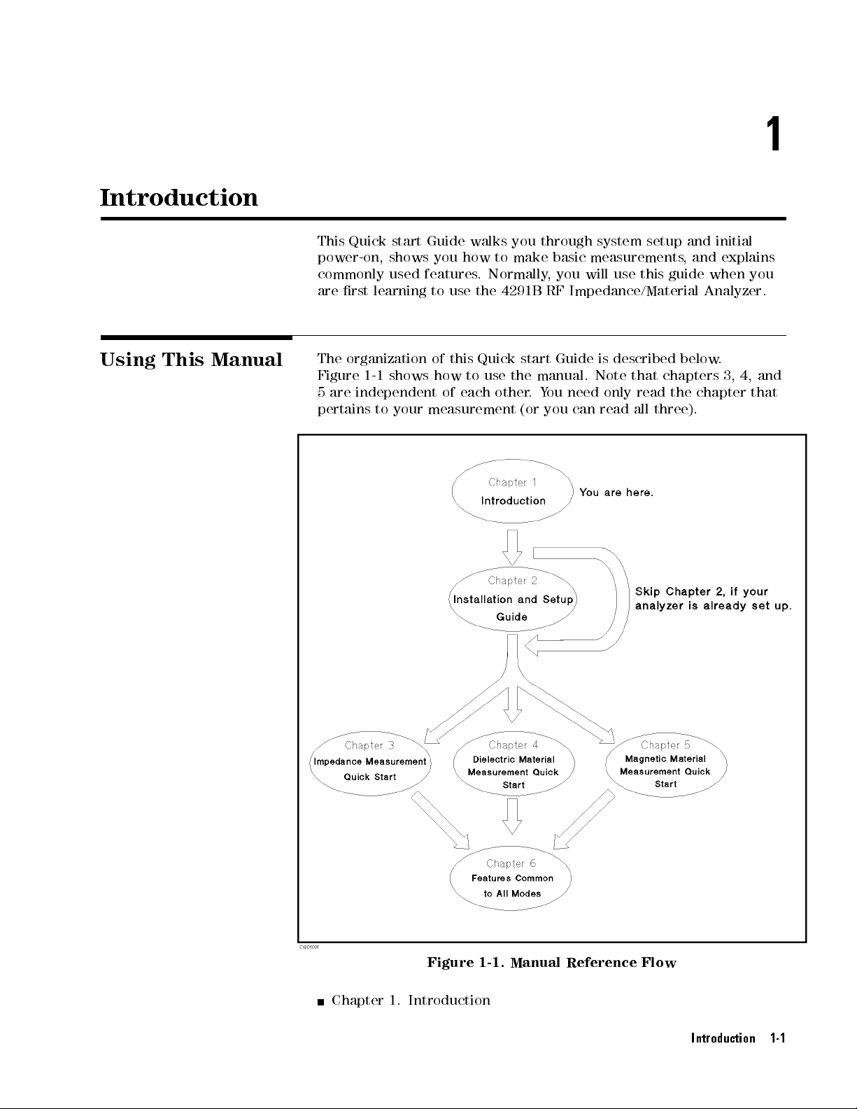
The
Figure
5
are
pertains
learning
organization
1-1
independent
to
start Guide
shows
used
you
features
to
of this
shows
how
of
your
measurement
walks
how
.
use
the
Quick start
to use
each
you
to
make
Normally
4291B
the manual.
other
.
(or
through
basic
,
RF
system
measurements
you
will
use
Impedance/Material
Guide is
described below
Note
Y
ou
need
only read
you
can
read
this
that
all
setup
guide
chapters
the
three).
and
,
and
Analyzer
chapter
initial
explains
when
.
3,
4,
you
.
and
that
Figure 1-1. Manual Reference Flow
Chapter 1. Introduction
Introduction 1-1
Page 18
This chapter
use this
manual.
provides a
brief description
of the
4291B and
how
to
Chapter 2.
This chapter
an incoming
refer to
set up
Chapter
This
for operation.
3.
chapter
measurement.
Chapter 4.
This
chapter
measurement.
Option
Chapter
This
002
5.
chapter
measurement.
Option
Chapter
This
002
6.
chapter
features
modes
of
Installation and
provides the
inspection and
this chapter
Impedance
if
Measurement
provides
Dielectric
Material
provides
Dielectric
is
installed.
Magnetic
Material
provides
Magnetic
is
installed.
F
eatures
Common
provides
and
measuremnent
operation
(impedance
Set Up
Guide
information necessary
the
setting up
analyzer
your
has
Quick
a
quick
start
guide
Measurement
a
quick
start
guide
material
measurement
Measurement
a
quick
start
guide
material
the
procedures
measurement
to
All
Modes
for
technique
,
dielectric
not
Start
that
analyzer
been
for
impedance
Quick
for
dielectric
Quick
for
magnetic
the
analyzer
can
,
and
for
performing
.
Y
ou
inspected
Start
material
is
available
Start
material
is
available
key
be
used
magnetic).
should
when
in
all
and
when
Appendix
This
repair
Appendix
This
16191A
A.
appendix
,
line
B
appendix
and
Compensation
Appendix
This
C. Calibration
appendix provides
Compensation.
Maintenance
provides
voltage
.
Compensation
setting
provides
16193A
"in
Chapter 3.
information
changes
Procedure
the
compensation
.
This
appendix
and Compensation
the explanation
on
performance
,
and fuse
for
16191A
is
referred in
of Calibration
verication,
replacement.
and 16193A
procedure for
\5. Fixture
the
and
1-2 Introduction
Page 19
Brief
of
Description
the 4291B
F
or surface-mount
4291B
designed
F
and
RF Impedance/Material
to
provide
or component
material researchers
component evaluation
Analyzer is
accurate testing
manufacturers,
,the
RF and
4291B provides
and material
an integrated
at higher
frequencies.
digital equipment
these capabilities:
testing, the
package
designers,
A
dditional
F
eatures
Broad
components
Improved
impedance
frequency coverage
and
materials
measurement accuracy
range of
Surface-mount-device
capacitors
Dielectric
permittivity
002
and
Magnetic
permeability
Direct
humidity
Impedance
Evaluate
(with Option
Chapter
Monitor
OSC
and inductors
test xture
, including
16453A
test
).
xture
of
ferrite
impedance
,
or temperature
Measurement
components
001).
6.)
test
signals
Level
or
the
and material
Dc
from 1
.
0.1
to
50
(SMD) test
.
and
built-in
Cole-Cole
and built-in
material
(with an
with
(See
\Applying
applied
Bias
Level"
MHz to
1.8 GHz
and repeatability
k
xtures for
function
plot
relaxation
function
(with
Option
dierent sizes
for
measuring
time
for
measuring
002
and
parameter measurement
external temperature
dc
bias
up
to
6
100
mA
Dc
Bias
(Option
to
your
DUT
s
.
(See
\Monitoring
in
Chapter
6.)
for
over
(with
16454A
and
001
testing
RF
an
of
chip
Option
).
versus time
chamber).
6
40
V
Only)"
in
the
,
Simulate
\Equivalent
a
component
Circuit
with
Analysis"
equivalent
in
Chapter
Others
Store
the
and
LIF
(See
\Saving
Markers
measurement
compatible
and
and
marker
data
1.4
MB
Recalling"
utilities
and
oppy
in
Chapter
(See
analyzer's
disk
\Using
Chapter 6.)
Limit lines for go/no-go testing (See \P
Test" in Chapter 6.)
Frequency linear/log/list sweep (See \P
Measurement" in Chapter 6 for list sweep
circuit
analysis
.
(See
3.)
drive
settings
and
on
the
memory
DOS
disk.
6.)
the
Marker"
in
erforming a GO/NO-GO
erforming
a List Sweep
.)
Introduction 1-3
Page 20

Page 21
2
Installation
and Set
This chapter
the following
Incoming Inspection
Power
Replacing
Operation
Ventilation
Instruction
Rack/Handle Installation
Connecting the
Connecting the
Connecting
Connecting
Up Guide
provides
information:
Requirements
the
Fuse
Conditions
Requirements
for
Cleaning
T
est
T
est
a
BNC
A
a
Keyboard
installation
Station
Head
dapter
and
setup
instructions
.
It
contains
Incoming
Inspection
W
arning
T
o
avoid
when there
outer enclosure
Inspect
hazardous
are
the
shipping
electrical
signs
(for
container
of
shipping
example
shock,
,
covers
for
damage
do
damage
,
panel,
.
not
to
If
turn
on
the
any
portion
or
display)
the
shipping container
analyzer
of
the
or cushioning material is damaged, it should be kept until the contents
of the shipment have been checked for completeness and the analyzer
has been checked mechanically and electrically
the shipment should be as listed in T
able 2-1. If the contents are
. The contents of
incomplete, if there is mechanical damage or defect, or if the analyzer
does not pass the power-on selftests
Technologies oce
. If the shipping container is damaged,
cushioning material shows signs of unusual stress
, notify the nearest Agilent
or the
, notify the carrier
as
well as the Agilent Technologies oce. Keep the shipping materials
for the carrier's inspection.
Installation and Set Up Guide 2-1
Page 22
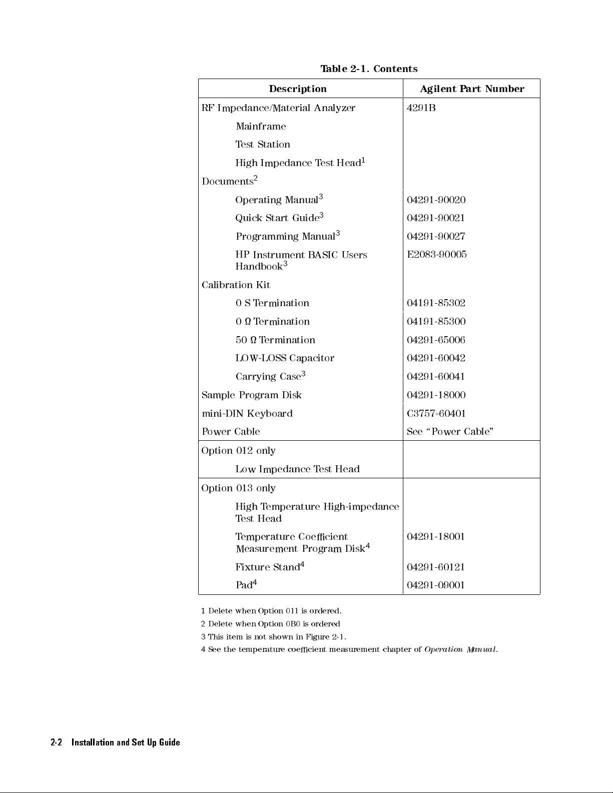
T
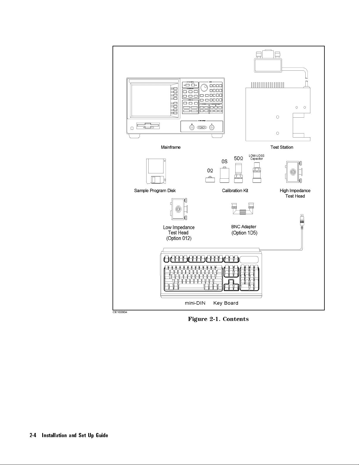
able 2-1.
Contents
Description Agilent P
RF
Impedance/Material Analyzer
Mainframe
T
est
Station
High
Impedance
Documents
Calibration
2
Operating
Quick
Manual
Start
Programming
HP
Instrument B
Handbook
3
Kit
0
ST
ermination
0
T
ermination
50
Termination
LOW-LOSS
Carrying
Capacitor
Case
Guide
Manual
ASIC
3
T
est
3
3
Head
3
Users
art Number
4291B
1
04291-90020
04291-90021
04291-90027
E2083-90005
04191-85302
04191-85300
04291-65006
04291-60042
04291-60041
Sample
mini-DIN
P
ower
Option
Option
1
Delete when Option 011 is
2
Delete when Option 0B0 is ordered
3
This item is not shown in Figure 2-1.
4
See the temperature coecient measurement chapter of
Program
Disk
Keyboard
Cable
012
only
Low
Impedance
013
only
High T
Test
T
emperature High-impedance
Head
emperature
T
est
Head
Coecient
Measurement Program Disk
Fixture Stand
4
Pad
4
ordered.
4
04291-18000
C3757-60401
See
\P
ower
04291-18001
04291-60121
04291-09001
Operation Manual
Cable
"
.
2-2 Installation and Set Up Guide
Page 23
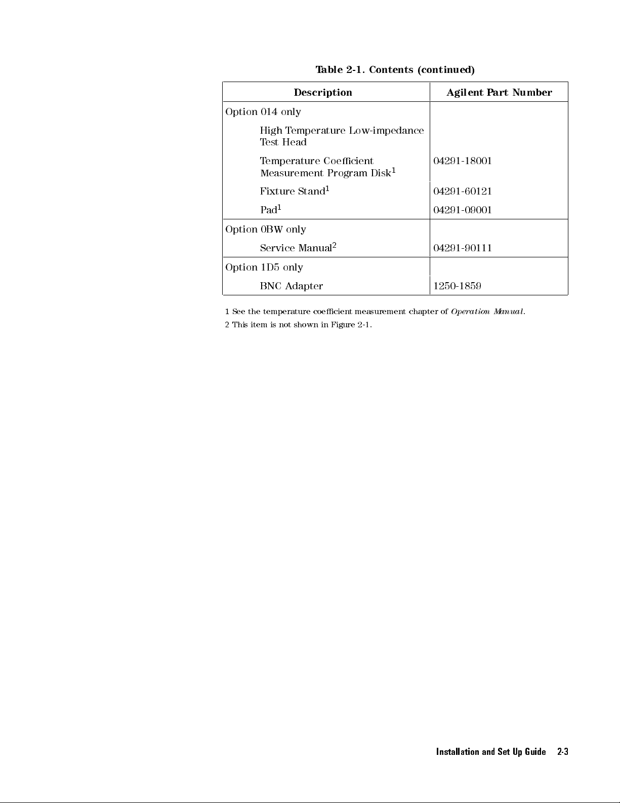
T
able 2-1.
Contents (continued)
Option
Option
Option
1
See
2
This
Description Agilent P
014
only
High
Temperature
T
est
Head
T
emperature Coecient
Measurement
Fixture
1
P
ad
0BW
only
Service
Stand
Manual
1
Program Disk
1D5 only
BNC
A
dapter
the
temperature
item
is not
coecient
shown in
Figure 2-1
Low-impedance
2
measurement
.
1
04291-18001
04291-60121
04291-09001
04291-90111
1250-1859
chapter
of
Operation
art Number
Manual
.
Installation and Set Up Guide 2-3
Page 24
2-4 Installation and Set Up Guide
Figure 2-1.
Contents
Page 25
P
ower
Requirements
The
4291B requires
V
oltage :
90 to
the following
132 V
ac,
198 to
power source:
264 V
ac
P
ower
W
arning
Cable
Frequency
P
ower :
In
accordance
is
equipped
appropriate
frame
.
The
type of
the
country of
of
the power
F
or
protection
must
not
The
power
protective
:47
to 63
300 V
A maximum
with
international
with
a
three-wire
ac power
power cable
destination. Refer
cables available
from
be
defeated.
plug
must
earth
ground
Hz
power cable
outlet, this
shipped with
.
electrical
be
plugged
connection.
safety
standards,
. When
cable grounds
each instrument
to Figure
shock,
into
2-2 for
the power
an
outlet
this instrument
connected to
the
instrument
depends
the
part
cable ground
that
provides
an
on
numbers
a
Installation and Set Up Guide 2-5
Page 26
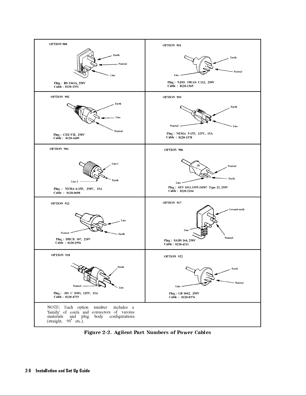
Figure 2-2. Agilent Part Numbers of Power Cables
2-6 Installation and Set Up Guide
Page 27
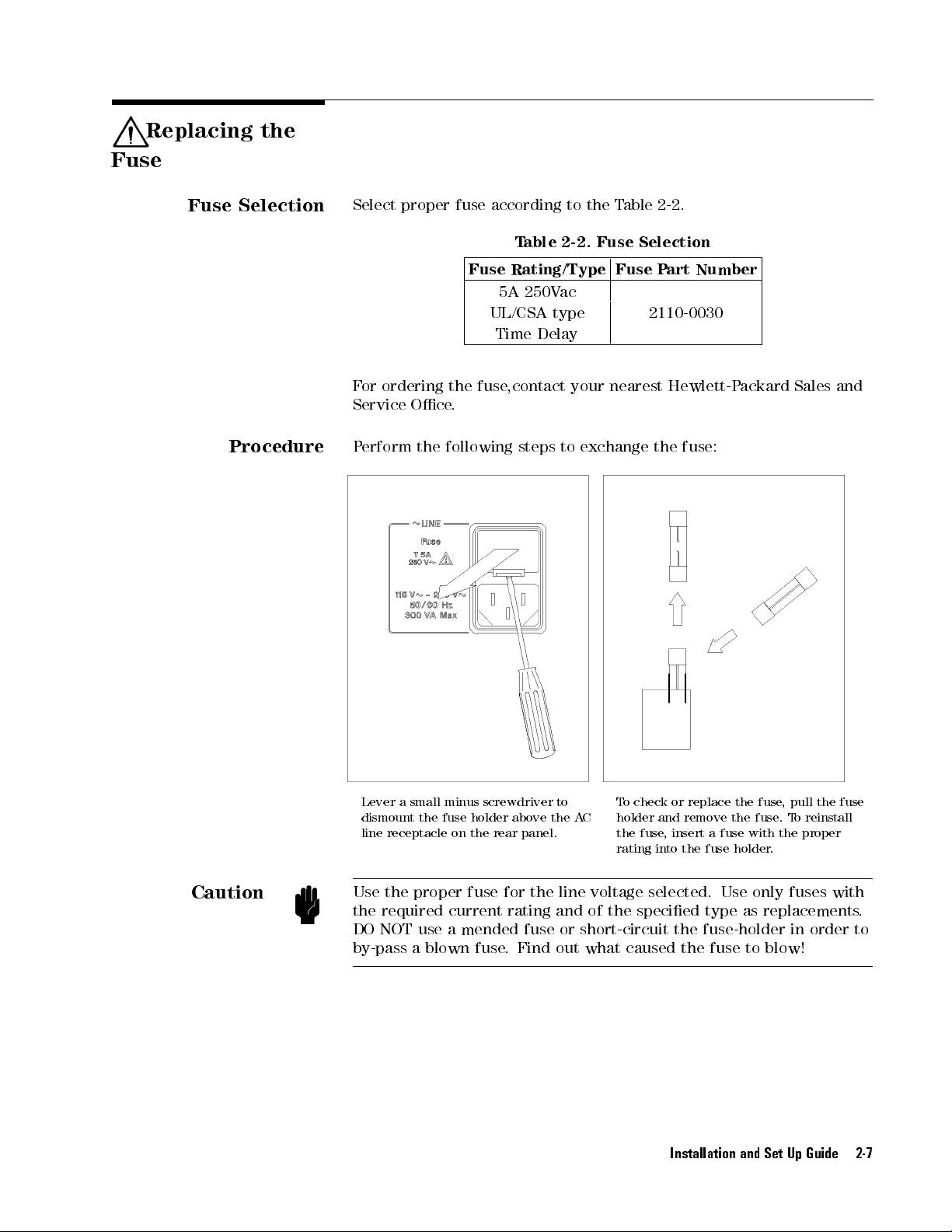
Replacing the
Fuse
Fuse
Procedure
Selection
Select
F
or
ordering
Service
P
erform
proper fuse
Fuse
the
Oce
.
the
following
according to
T
able 2-2.
Rating/Type
5A
250V
UL/CSA
Time
Delay
fuse
,contact
steps
the T
Fuse Selection
ac
type
your
to
exchange
able 2-2
Fuse
2110-0030
nearest
.
P
art
Number
Hewlett-P
the
fuse:
ackard
Sales
and
Caution
T
o
check
fuse
or
replace the
remove
,
insert a
fuse
the
fuse,
fuse
with
.
the
.
pull the
T
o
reinstall
proper
fuse
Lever
a
small
dismount the
line
receptacle
minus
fuse
on
holder
the rear
screwdriver to
above
the
panel.
holder and
A
C
the
rating into the fuse holder
Use the proper fuse for the line voltage selected. Use only fuses with
the required current rating and of the specied type as replacements
DO NOT use a mended fuse or short-circuit the fuse-holder in order to
by-pass a blown fuse
.Find
out what caused the fuse to blow!
Installation and Set Up Guide 2-7
.
Page 28
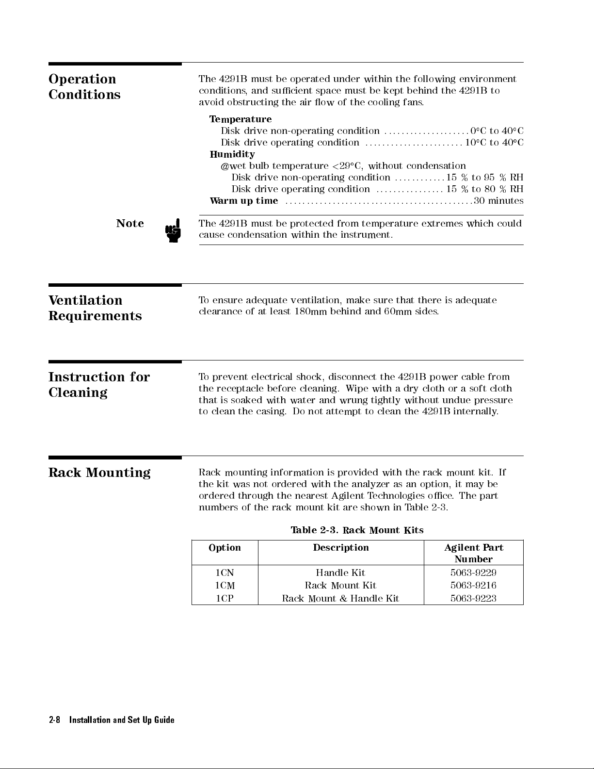
Operation
Conditions
Note
V
entilation
Requirements
The
4291B must
conditions
avoid
obstructing
T
emperature
Disk
Disk
Humidity
@wet
Disk
Disk
W
arm up
The
4291B
cause
condensation
T
o
ensure
clearance
be operated
, and
sucient space
the
air ow
drive non-operating
drive operating
condition
bulb temperature
drive non-operating
drive operating
time
must
adequate
of at
:
::
:
:
:
:
:
be
protected
within
ventilation,
least 180mm
:
the
:
under within
must be
of the
cooling fans
condition
:
::
C,
<
without condensation
29
condition
condition
:
:
:
:
:
:
:
:
:
:
::
from
temperature
instrument.
make
sure
behind and
the following
kept behind
:
::
::
::
::
::
:
:
:
:
:
:
:
:
:
:
:
:
:
:
:
:
:
:
:
:
:
:
::
::
::
:
:
:
that
60mm sides
the 4291B
.
:
:
:
:
:
:
:
:
:
:
:
:
:
:
:
:
:
:
:
:
:
:
:
:
:
:
:
:
:
:
:
:
extremes
there
.
environment
:
15
15
:
:
:
C
:
:
:
:
0
C
:
:
:
10
%
to
95
%
to
80
:
:
:
:
:
30
minutes
which
is adequate
to
to 40
to 40
%
%RH
could
RH
C
C
Instruction
Cleaning
Rack
Mounting
for
T
o
prevent
the
receptacle
that
is
to
clean
Rack
the
kit
ordered
numbers of
electrical
soaked
the
casing.
mounting
was not
through
the rack
shock,
before
with
cleaning.
water
Do
not
information
ordered with
the nearest
mount kit
Table 2-3.
disconnect
Wipe
and
wrung
attempt
is
to
provided
the analyzer
Agilent T
are shown
Rack Mount Kits
the
with
tightly
clean
with
4291B
a
as an
power
dry
cloth
without
the
4291B
the
rack
option,
echnologies oce
in T
able 2-3
cable
or
a
undue
internally
mount
it
. The
.
Option Description Agilent P
Number
1CN Handle Kit 5063-9229
1CM Rack Mount Kit 5063-9216
1CP Rack Mount & Handle Kit 5063-9223
soft
pressure
kit.
may
part
from
cloth
.
If
be
art
2-8 Installation and Set Up Guide
Page 29
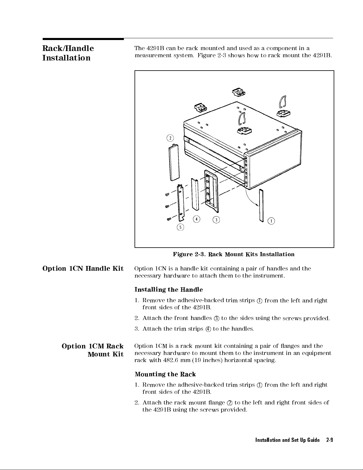
Rack/Handle
Installation
The
4291B can
measurement
be rack
mounted and
system. Figure
used as
2-3 shows
acomponent
how to
rack mount
in a
the 4291B
.
Option 1CN
Option 1CM Rack
Handle
Kit
Mount Kit
Figure
Option
necessary
Installing
1.
2.
1CN is
hardware to
the
Remove
front
the
sides
Attach the
a
of
front
3. Attach the trim strips
2-3.
Rack
handle
kit
containing
attach them
Handle
adhesive-backed
the
4291B
.
handles
3
4
to the handles
Mount
trim
to
the
a
to
strips
sides
Kits
pair
of
the
instrument.
1
using
.
Installation
handles
from
the
the
screws
and
left
the
and
right
provided.
Option 1CM is a rack mount kit containing a pair of anges and the
necessary hardware to mount
rack with 482.6 mm (19
them to the instrument in an equipment
inches) horizontal spacing.
Mounting the Rack
1. Remove the adhesive-backed trim strips1
from the left and right
front sides of the 4291B.
2. Attach the rack mount ange2
to the left and right front sides of
the 4291B using the screws provided.
Installation and Set Up Guide 2-9
Page 30
3. Remove
slide the
all four
feet (lift
foot toward
bar on
the bar).
the inner
side
of
the
foot,
and
Option 1CP
Mount
Rack
&Handle
Kit
Option
1CP
necessary
handles
attached,
spacing.
Mounting
1.
Remove
front
sides
2.
Attach
on
the
provided.
3.
Remove all
slide
the foot
is
a
rack
mount
hardware
the
the
of
the
front handle
left
and right
to
mount them
in
an equipment
Handle
adhesive-backed trim
the 4291B
front sides
four feet
toward the
kit
and
.
3
(lift bar
bar).
containing a
to an
rack with
Rack
strips
and the
rack mount
of the
on
the
pair of
anges and
instrument which
482.6 mm
1
from
the
ange
4291B using
inner
side
of
the
has
(19 inches)
left
and
5
together
the
screws
foot,
the
right
and
2-10 Installation and Set Up Guide
Page 31

Connecting
T
est Station
the
The
4291B consists
head.
in
turn
The connection
Figure
o the
2-4
.While
analyzer.
of the
mainframe,
of the
you connect
the test
test station
the test
station, and
and the
station to
the test
mainframe is
the mainframe
shown
,
Figure
1. Engage the two type-N connectors (labeled
and the center connector
2-4.
Connecting
the
T
est
Station
to
the
Mainframe
S
and
R
, respectively)
.
2. Turn the two type-N connectors to tighten the connection.
Installation and Set Up Guide 2-11
Page 32

Connecting
T
est Head
the
Selecting the
Connecting
Head
to
Test
Head
the
T
est
the
T
est
Station
Agilent
Technologies
Impedance
impedance
An
analyzer
can
measure
accuracy
the
DUT is
head
provides better
test
head. F
Operation
How
to
connect the
Figure
2-5
T
est
test
head
that
all
drops at
less than
or more
Manual
.
When
provides two
Head and
the Low
is furnished
is
equipped
measurement
with a
ranges
low impedances
approximately 10
measurement accuracy
selection information
.
test head
you replace
to the
the test
kinds of
test heads:
Impedance T
when Option
high impedance
. However
. Usually
,
the
,
when
than the
, see
test station
head,
turn
est Head.
012 is
,the
the
low
impedance
the
is
shown
o
the High
The
low
ordered.
test head
measurement
impedance
test
high impedance
chapter
12
in
the
analyzer
of
of
the
.
2-12 Installation and Set Up Guide
Figure 2-5. Connecting the T
1. Insert
the test head into the test station along the guide rail.
est Head to
the T
2. Tighten the two knobs on the test head to x the
test station.
est Station
test head to the
Page 33

Connecting
A
dapter (Option
1D5
Only)
a
BNC
When
REF
Option 1D5
OVEN
analyzer
improves
is installed,
output and
.
The
BNC adapter
the frequency
connect a
the EXT
REF Input
is included
accuracy and
BNC adapter
on the
in Option
stability of
between the
rear panel
1D5. Option
the analyzer
of the
1D5
.
Connecting
K
eyboard
Figure
A
a
mini-DIN
the
rear
easier
Instrument
functions
the
mini-DIN
keyboard can
panel
way
to
B
by
of the
enter characters
ASIC
using
keyboard,
2-6.
be
analyzer
programs
keyboard
see
Connecting
connected
.
The
mini-DIN
for
the
.
It
can
also
function
the
Programming
a
to
le
access
keys
BNC A
the
mini-DIN
keyboard
names
the
.
F
or
Manual
dapter
,
display
analyzer
more
connector
provides
titles
,
and
softkey
information
.
on
an
on
Installation and Set Up Guide 2-13
Page 34
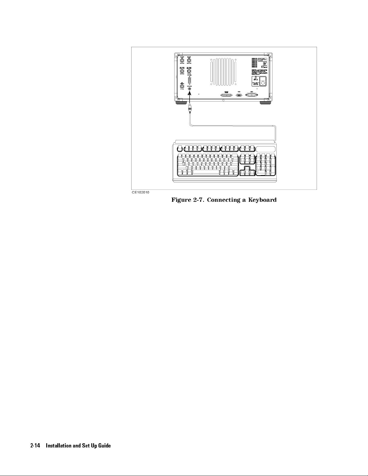
Figure
2-7.
Connecting
a
K
eyboard
2-14 Installation and Set Up Guide
Page 35

3
Impedance
Overview
Measurement Quick
This
chapter
measurements
analyzer
learn
how
as
examples
learned how
(1). Frequency
(2).
Frequency
(3).
OSC
(4).
Dc
factor
by
performing
to
.
level
bias
.
provides
.
New
use
At
to get
a
users
the analyzer
the end
the following
characteristics of
characteristics of
characteristics
voltage
characteristics
quick
these
Start
start
can quickly
procedures.
,the
of the
quick start
of
guide
for
impedance
become familiar
In this
chapter,
capacitor measurements
procedures,
measurement results:
impedance.
capacitance and
capacitance
of
capacitance
and
dissipation
dissipation
and
with the
to
help
are used
you
will
factor.
dissipation
you
have
factor
.
In addition, you will also learn how to do the following:
Use the marker.
Approximate the equivalent circuit constants with actual
measurement results.
Impedance Measurement Quick Start 3-1
Page 36

Basic Measurement
Flow
Figure
3-1 shows
the basic
ow for
an impedance
measurement.
3-2 Impedance Measurement Quick Start
Figure 3-1. Basic Flow for Impedance Measurements
Page 37

Required Equipment
T
o
perform
required:
all the
steps in
this quick
start, the
following equipment
is
4291B
T
RF Impedance/Material
est Head
High
Impedance T
Low
Impedance T
Calibration
T
est Fixture
16191A
16192A
16193A
Shorting
Device Set
Tweezers
Device
guide
Under T
.)
est Head,
est Head
Kit
Side Electrode
Parallel
Small Side
Electrode SMD
Electrode SMD
(Included with
(Included with
est (DUT)
Analyzer
or
SMD T
16191A,
(A
chip
est Fixture
Test
Fixture
Test
16191A
16192A
capacitor
,
or
,
or
Fixture
,
16192A
,
and
16193A
is
demonstrated
,
and
)
16193A
in
this
)
Figure
3-2.
Required
Impedance Measurement Quick Start 3-3
Equipment
Page 38

1.
P
ower
ON
Note
V
erify the
you
turn ON
1.
Press the
After
installed
displayed.
Only
the
they
are
rear
panel.
test station
the analyzer
LINE switch.
the power-on
options and
option
installed).
numbers
Other
and the
.If
necessary,
test head
are correctly
see Chapter
self-test (approximately
the connected
for
001
installed
and
option
test head
002
are
numbers
set up
2.
10 seconds),
information are
displayed
are
at
listed
before
the
power-on
on
the
(if
2. Calibration
After turning
to stabilize
Calibration
test
head.
the instrument.
denes
The
turned ON.
specied
and
measurement
low-loss
on the
calibration
After
the
capacitor
analyzer
the
measurement
must
calibration,
accuracy
in
the
,
a
30
minute-warm-up
accuracy
be
performed
the
.
The
calibration
analyzer
0
S,
0
kit
are
at
when
can
,
and
required.
period
the
APC-7
the
measure
50
is
required
R
on
the
analyzer
is
within
terminations
its
3-4 Impedance Measurement Quick Start
Figure 3-3. Calibration
Page 39

Calibration Procedure
1.
2.
3.
4.
Press
Press
Turn
Figure
V
erify
Figure
5
.
4
Cal
N
NN
NN
NN
NN
N
N
N
N
N
N
N
N
N
N
N
CALIBRATE
the
APC-7
3-4
.
that
the
3-5
.
NN
NN
NN
NN
NN
NN
NN
N
N
N
MENU
R
connector
connector
N
N
N
N
N
N
N
.
on
the
test
head
as
sleeve
is
extended
shown
fully
as
in
shown
in
5.
Connect
in
Figure
Figure
the
3-6
3-4.
0
S
termination
.
to
the
APC-7
Figure
R
connector
3-5.
Figure 3-6.
NNNNNNNNNNN
6. Press
OPEN
NNN
.
After an OPEN calibration sequence of about 1 minute,the
softkey label is underlined.
as
shown
NNNNNNNNNNNNNN
OPEN
7. Disconnect the 0 S termination.
Impedance Measurement Quick Start 3-5
Page 40

8.
Connect the
in
Figure 3-7
0
termination on
.
the APC-7
R
connector
as shown
9.
Press
After
softkey
10.
Disconnect
11.
Turn
shown
12.
V
Figure
erify
N
NN
N
N
N
N
N
SHORT
a
SHORT
label
only
in
that
3-9.
Figure
N
N
N
N
N
N
N
N
N
.
is
the
the
Figure
the
3-7.
calibration
underlined.
0
termination.
R
APC-7
3-8
.
connector
sequence
connector
sleeve
of
about
nut
of
the
is retracted
1
minute
50
termination as
fully
as
,
the
shown
N
N
N
N
N
N
N
N
N
N
N
SHORT
in
N
N
N
N
N
N
3-6 Impedance Measurement Quick Start
Figure 3-8. Figure 3-9.
13. Connect the 50 termination on the APC-7
in Figure 3-10.
R
connector as shown
Page 41

14.
Press
After a
softkey
15.
Disconnect
Figure
N
N
N
N
N
N
N
LOAD
LO
label
N
N
N
N
N
N
N
.
AD
the
3-10.
calibration
is
underlined.
50
termination.
sequence
of
about
2
minutes
,
the
N
N
N
N
N
N
N
N
LOAD
N
N
N
N
N
N
Note
Low-loss
The
Q
measurements
capacitor
low-loss
measurements
16.
Connect
in
Figure
calibration
capacitor
.
,
the
the
3-11
calibration allows
If you
low-loss
low-loss
.
Figure 3-11.
(steps
don't
need
16
this
through
capacitor calibration
capacitor
to
the APC-7
more
accurate
accuracy
18)
is
for
can
be
R
connector
optional.
high
high
Q
skipped.
as
shown
NNNNNNNNNNNNNNNNNNNNNNNNNNNNNNNNNNNNNNNNNNNNNNNNNNNNNNN
17. Press
N
LOW-LOSS CAPACITOR
After a low-loss capacitor calibration sequence of about 1 minute,
NNNNNNNNNNNNNNNNNNNNNNNNNNNNNNNNNNNNNNNNNNNNNNNNNNNNNNNN
the
LOW-LOSS CAPACITOR
.
softkey label is underlined.
18. Disconnect low-loss capacitor.
Impedance Measurement Quick Start 3-7
Page 42

Note
19.
Press
20.
Verify
screen.
The
calibration data
Handling
Keep
connectors
N
NN
NN
NN
NN
NN
NN
NN
N
N
DONE:CAL
the
two
and
Storage of
N
N
N
N
N
N
N
N
N
.
\
CO+
is
clean.
"
notations
erased
the APC-7
when
are
displayed
the
analyzer
R
Connector:
on
is
turned
the
left
of the
o.
3.
Connecting
T
est
Fixture
Selecting
the
a
T
est
Fixture
DUT
Do not
Do not
Before storing,
Use end
Never store
Agilent
dierent
xtures
Length
(mm)
touch the
set connectors
extend the
caps over
connectors loose
T
echnologies
sizes
of
surface
provide
T
able
high
3-1.
mating plane
surfaces
.
contact-end down.
sleeve or
the mating
provides
mounted
stability
T
est Fixtures
in
the
and
connector nut.
plane surfaces
a
box
or
a
drawer
test
xtures
device
(SMD)
repeatability
Specication
.
.
listed
in
T
able 3-1
measurements
measurements
(1/2)
16191A 16192A 16193A
2.0
to
12.0
1.0
to
20.0
1
0.5
to
.
.
3.2
for
These
DUT Width
DUT
Height
DUT Connection
1
When you measure a DUT with a length of more than 5 mm, see chapter 2 of
Parallel Electrode SMD T
conguration.
28=Fixture's Electrodes
3-8 Impedance Measurement Quick Start
(mm)
(mm)
0.5 to
0.5
to
5
5
2
est Fixture Operation and Service Manual
0.5 to
0.5
to
5
5
for the electrodes'
less than
less
than
the
16192A
3
3
Page 43

T
est Fixtures
Specication (2/2)
16194A
Connecting
Fixture to
the
the T
Head
T
est
est
This
T
o
connect
below
1.
Turn
Figure
2.
V
erify
Figure
SIZE
DUT
1
8
Quick
.
(
Figure
the
(mm)
Connection
=Fixture's
start
Guide
your
3-14
APC-7
3-12
.
that
the
3-13
.
Electrodes
explains
xture to
shows
R
connector
connector
1
the
the
2
L
how
T
est
Head,
connection
on
the
sleeve is
<
15
a
15
H
5
0.2
d
to
use
these
perform
for
16192A
test
head as
retracted fully
h
4.5 D
8
test
the
shown in
as
W
21
xtures
steps
as
an
shown
0.2
.
listed
example
in
.)
Figure 3-12.
Figure 3-13.
3. Set the mounting posts of the test station into the twin locating
holes at the corner of the test xture
.
4. Connect the connector on the underside of the test xture to the
APC-7 connector on the test head.
Impedance Measurement Quick Start 3-9
Page 44
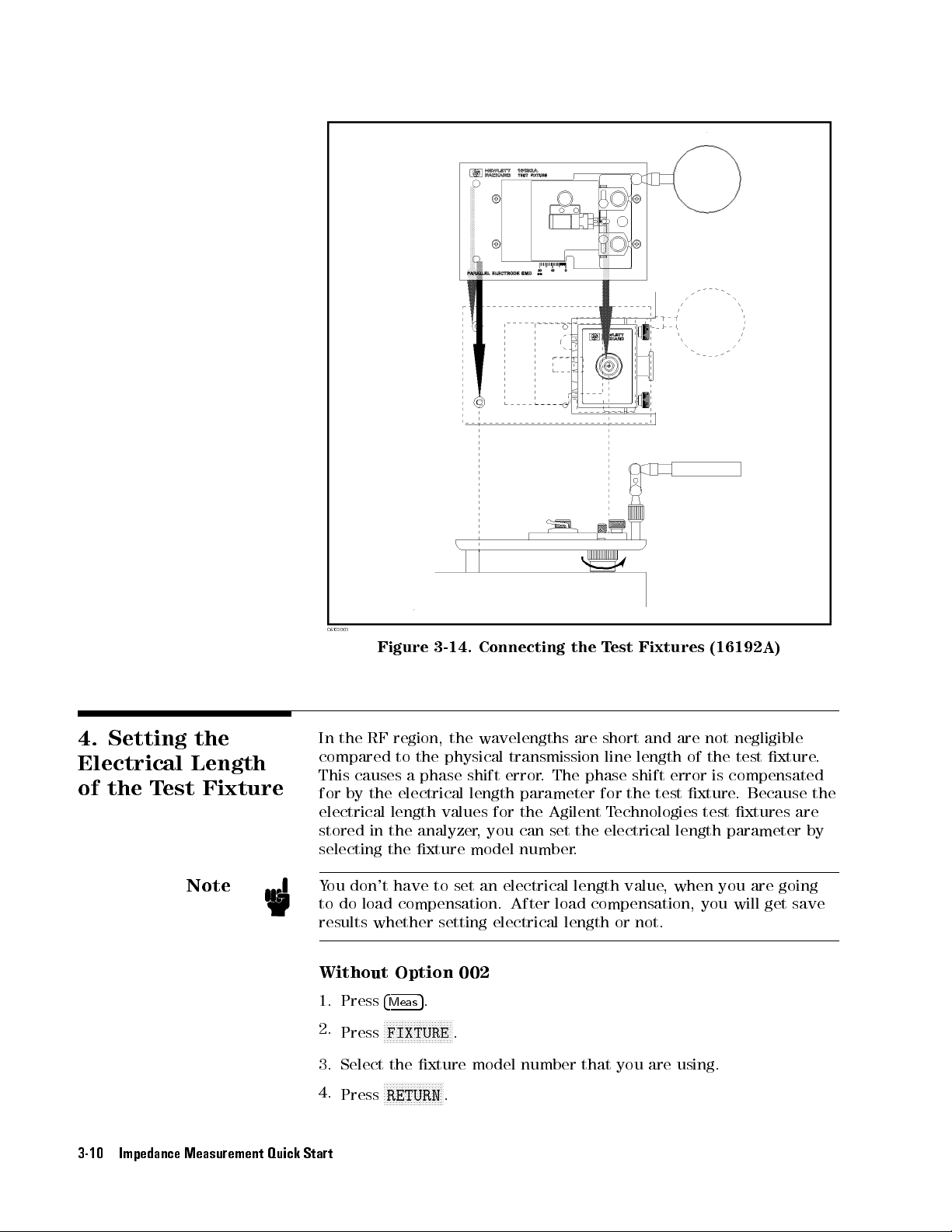
4.
Setting
Electrical
of
the T
est Fixture
the
Length
Figure
In
the
RF region,
compared
This
causes
for by
the
electrical length
stored
in
3-14.
to
the physical
a phase
electrical
the
analyzer
the wavelengths
values for
selecting the xture
Connecting
transmission line
shift error
length
,you
.The
parameter
the
Agilent
can
set
model number
the
T
est
are short
phase shift
for
T
echnologies
the
electrical
.
Fixtures
and
length of
the
test
are
error
xture
length
(16192A)
not
negligible
the
test
is
compensated
.
Because
test
xtures
parameter
xture
are
.
the
by
Note
You don't have to set an
to do load compensation. After load compensation, you will get save
results whether setting electrical length or not.
Without Option 002
1. Press
2.
3. Select the xture model number that you are using.
4.
3-10 Impedance Measurement Quick Start
Press
Press
4
5
.
Meas
NNNNNNNNNNNNNNNNNNNNNNN
FIXTURE
NNNNNNNNNNNNNNNNNNNN
RETURN
electrical length value
, when you are going
.
.
Page 45

5.
Verify
display
that two
.
\
Del
" notations
appear on
the
left
side
of
the
5.
Fixture
Compensation
With
1.
2.
3.
4.
5. Select
6.
7.
Fixture
test
Option 002
Press
4
Meas
N
NN
NN
FIXTURE
Press
V
erify
that
N
N
N
N
NN
SELECT
Press
the xture
N
NN
NN
RETURN
Press
V
erify
that
display
.
compensation
xture
N
N
NN
N
N
electrode
measurement
OPEN,
OPEN
SHORT
and
SHORT
5
.
N
N
N
N
N
N
N
N
N
NN
NN
the
NN
N
N
N
N
N
N
N
N
N
N
N
N
N
N
N
N
N
N
N
N
N
N
N
two
accuracy
and
N
NN
NN
N
N
N
N
N
N
N
N
N
N
N
NN
NN
NN
N
NN
NN
IMPEDANCE
N
N
N
N
N
N
N
N
N
N
N
N
NN
NN
NN
N
N
N
N
N
N
N
IMPEDANCE
N
N
N
N
N
N
N
N
N
NN
NN
NN
N
N
N
N
N
N
N
N
N
FIXTURE
model
N
NN
NN
N
N
N
N
RETURN
\
Del
N
N
N
N
N
N
N
N
"
number
N
N
N
.
notations
reduces
and
the
is
specied).
LO
AD
compensations
compensations
NN
NN
NN
N
N
N
N
N
N
N
N
N
N
N
NN
NN
[NONE]
N
N
N
N
N
N
N
N
N
N
N
N
NN
NN
NN
N
N
N
[NONE]
that
appear
the parasitic
test head
are
NN
NN
N
.
N
N
N
N
softkey
you
on
APC-7
Fixture
.
For
required.
label
is
underlined.
are
using.
the
left
side
of the
error existing
R
connector
between the
(where
compensation consists
basic
measurements
,
the
of
the
Figure 3-15. Fixture Compensation
Impedance Measurement Quick Start 3-11
Page 46

Performing
Compensation
SHORT
SHORT
test
xture.
Compensation corrects
for the
residual impedance
due to
the
Selecting
F
our dierent-dimension
xture;
shorting
The
dimensions for
the Shorting
extra four
device that
T
able 3-2.
short devices
is closest
each shorting
Dimension
1
2
1.6
2
2.4
2
2.4
2
0.5
2
0.8
2
0.8
2
0.8
2
1
Extra
short
devices
How
to
as
an
in
Appendix
perform
example
.
C.
SHORT
The
procedures for
Device
shorting devices
are attached
to the
device are
Dimension of
(mm)
1
2
2.4
2.4
2
2
2.4
2
3.2
2.4
2
4.5
0.5
2
1
0.8
2
1.6
1.2
2
2
1.6
2
3.2
of
Option
010
compensation for
are furnished
for
size
of
the
DUT
shown
Shorting Devices
Agilent
16191-29001
16191-29002
16191-29003
16191-29004
16191-29005
16191-29006
16191-29007
16191-29008
the
16192A
the
16191A
and
option
P
art
with each
010.
should
in
T
able
Number
1
1
1
1
is
shown
16193A
be
3-2
are
The
used.
.
below
shown
The names of each part are listed above
3-12 Impedance Measurement Quick Start
. 1. Loosen the three knobs
.
Page 47

2.
Move
outside.
4.
Place
electrode
stage
the
.
A and
shorting
the two
device
device holders
so
that
it
contacts
to the
the
3.
A
djust
on position
5.
A
djust
to
hold
the
stage C
s
.
the
two
shorting
so that
B
stages
device
the shorting
and
the
.
device is
two
device
placed
holders
6. Tighten the two B knobs to x
device holders.
the B stages and the
7.1
Push the lever
.
2
Slide stage A while pushing
the lever until the electrode on the stage A slightly
contacts the shorting device.
Impedance Measurement Quick Start 3-13
Page 48

8.
Tighten
knob
Awhile
pushing the
lever.
9. Release
the
lever
to
hold
the
shorting
device
.
P
erforming
Compensation
OPEN
SHORT
When
the
press
the
1.
Press
After
softkey
OPEN
xture
.
16192A
and
16193A
Compensation
test
xture
following
N
NN
NN
NN
N
N
N
N
N
N
N
N
FIXTURE
5
4
Cal
the
SHORT
label
is
underlined.
Compensation
How
to
perform
is
described
are
shown
Key
is
ready
front
panel
N
N
N
N
N
N
N
N
N
N
N
NN
NN
NN
N
N
N
N
N
N
N
N
N
N
COMPEN
compensation
corrects
as
an
in
for
an
OPEN
example
Appendix
Sequence
for
the
SHORT
keys:
N
NN
NN
NN
N
N
N
N
N
N
N
N
N
N
N
N
N
N
COMPEN
sequence
stray
compensation
.
The
C.
compensation
N
NN
N
N
N
N
N
MENU
NN
N
N
NN
NN
NN
N
N
N
SHORT
is
done
admittance
procedures
NN
N
N
N
N
N
N
N
N
N
N
.
,
the
due
to
sequence
for
the
sequence,
N
NN
N
N
N
N
N
N
N
N
N
SHORT
the
for
16191A
N
N
N
N
N
test
the
1. Set the DUT on the test
shorting device in the SHORT compensation.
OPEN Compensation K
When the test xture is ready for the OPEN compensation sequence,
perform the following procedure:
1.
3-14 Impedance Measurement Quick Start
xture just as you set the
2. Push the black lever and remove
ey Sequence
NNNNNNNNNNNNNN
Press
OPEN
.
After the OPEN compensation sequence is done,the
label is underlined.
the DUT
NNNNNNNNNNNNNN
OPEN
.
softkey
Page 49

2.
3.
Press
Verify
display
N
NN
NN
NN
NN
NN
DONE:
that
.
NN
NN
two
N
N
N
N
N
N
N
N
N
N
N
NN
NN
COMPEN
\
CMP
NN
NN
NN
NN
"
.
notations
appear
on
the
left
side
of the
Note
Note
6.
Connecting the
DUT
to
the
Fixture
T
est
Y
ou
can
do
NN
NN
NN
NN
NN
N
N
N
each compensation
N
N
N
N
N
N
N
N
N
NN
NN
NN
NN
NN
NN
NN
N
N
N
N
N
N
N
N
FIXTURE COMPEN
you
need
again.
Y
ou
have to
executing
If
you
set an
compensations
change the
compensations except
How
to
connect
example
Appendix
. The
the
procedures
C.
NN
NN
NN
NN
NN
N
N
N
N
N
N
N
N
N
N
N
NN
NN
NN
over again.
NN
NN
NN
RESUME CAL
electrical length
except for
electrical length
for load
DUT
to
the
for
the
NN
N
N
N
N
N
N
N
N
N
N
N
NN
NN
NN
NN
NN
NN
SEQUENCE
N
and
value
load compensation.
value,
compensation.
16192A
16191A
is
shown
and
Press
4
Cal
do
on
4291B
you have
in
16193A
5
compensations
before
to
retry
xture
below
are
as
an
shown
only
in
1.
Push
the
7. Setting up the
Analyzer
lever
and
place
the
DUT
on
the
electrode.
Before you start the measurement, you
t your measurement requirements
2. Release
the lever
to hold
the
DUT
must set up the analyzer to
. This section
provides the set up
procedures for the following measurements:
Frequency characteristics of
jZj-
Frequency characteristics of C-D
OSC level characteristics of C-D
dc bias voltage characteristics of C-D
The set up procedure for each measurement is described in the
following pages. Set up your analyzer according the applicable
procedure.
Impedance Measurement Quick Start 3-15
.
Page 50

7-1. Setting
j
Z
j
-
vs.
Frequency
up for
The
example setup
T
able 3-3.
for this
MEASUREMENT Block
measurement is
as follows
Parameter
.
Setting
P
arameter
F
ormat
T
able
Sweep
Sweep Type
Frequency
OSC
Level
T
o
set
up
the
following
MEASUREMENT
1.
2.
3.
4.
STIMULUS
5.
6.
4
Meas
4
Meas
4
F
o
4
F
o
4
Sweep
4
Sw
rmat
rmat
eep
procedure:
5
4
Chan 1
5
4
Chan
5
4
5
4
N
N
N
SWEEP
5
N
NN
SWEEP
5
3-4.
P
arameter
Range
analyzer
N
N
IMPEDACE:
5
N
NN
PHASE:
5
2
5
Chan
1
5
Chan
2
Block
N
N
N
N
N
N
N
N
N
N
N
N
N
N
N
N
N
N
N
N
N
N
N
N
N
N
N
N
N
N
N
N
STIMULUS
,
press
Block
N
N
N
N
N
N
N
N
N
N
N
N
N
NN
NN
NN
NN
NN
NN
N
N
N
N
N
N
N
N
N
N
N
N
NN
N
N
N
N
N
N
N
N
N
N
N
N
N
N
N
LOG
Y-AXIS
N
N
N
NN
N
N
N
N
N
N
N
N
N
N
N
N
LIN
Y-AXIS
N
N
N
N
MENU
N
N
MENU
N
NN
N
N
N
N
N
N
N
N
N
SWP
N
NN
N
N
N
NN
NN
N
N
N
N
LOG
Channel 1
the
N
N
N
N
N
N
N
N
N
N
N
N
N
MAG
N
N
N
N
N
NN
NN
NN
NN
(
z)
N
N
N
N
N
N
NN
NN
N
N
N
N
N
N
N
N
N
N
N
N
N
N
N
NN
N
N
N
N
N
N
N
N
N
N
N
N
N
N
N
SRC:
N
N
N
N
N
N
N
N
P
arameter
Frequency
1
MHz
500
N
N
N
(Ch1
(Ch2
(Ch1
(Ch2
N
N
N
N
N
(Sweep
(Sweep
Channel 2
Log
to
1.8
GHz
mV
as shown
P
P
F
F
Setting
Z
Log Linear
Block
front
panel keys
N
N
N
N
N
N
NN
NN
NN
N
N
N
N
N
N
N
(
j
Z
j
)
N
N
N
N
N
N
NN
N
N
N
N
N
N
N
N
N
N
N
N
N
FREQ
Setting
Setting
arameter
arameter
ormat
ormat
=
=
=
Frequency)
Type
=
in
the
=
j
=
Log)
Linear)
Log)
Z
j
)
)
If
Only)"
3-16 Impedance Measurement Quick Start
7.
8.
9.
you want
Jump to \Display Annotations"
5
4
4
Start
1
5
4
4
Stop
1
5
4
Source
in Chapter
5
5
4
N
NN
N
OSC
to
4
M/
5
4
.
N
N
N
N
N
N
N
apply
5
5
4
8
G/n
N
N
N
N
N
N
N
N
N
LEVEL
6.
5
N
N
NN
NN
NN
N
5
5
4
4
0
.
dc
bias
,
refer
(Start
=
1
MHz)
(Stop
=
1.8
GHz)
(OSC
Level
=
500
5
5
4
4
5
x1
to
\Applying
Dc
Bias
(Option
mV)
001
Page 51

7-2. Setting
C
-D
vs.
Frequency
up for
The
example setup
T
able 3-5.
for this
MEASUREMENT Block
measurement is
as follows
Parameter
.
Setting
P
arameter
F
ormat
1
The
impedance
the
T
able
Sweep
Sweep
Frequency
OSC
T
o
set
up
the
following
MEASUREMENT
1.
2.
3.
4.
4
Meas
4
Meas
4
F
4
F
o
rmat
o
rmat
procedure:
5
4
Chan
5
4
Chan
5
4
5
4
selection
Operation Manual
Level
analyzer
Chan
Chan
of
,
see
3-6.
STIMULUS
P
arameter
Type
Range
,
Block
N
N
N
N
N
NN
NN
N
N
CAPACITNCE:
5
1
N
N
N
N
N
N
N
N
NN
NN
D
FACTOR:
5
2
N
N
N
N
N
N
N
LIN
5
1
N
N
N
N
N
N
N
LIN
5
2
parallel
the
press the
N
N
N
N
N
N
N
N
N
N
N
N
N
N
N
N
N
N
N
N
N
NN
N
Y-AXIS
N
N
N
NN
N
N
N
N
Y-AXIS
Channel 1
(Cp)
impedance measurement
N
N
N
N
N
N
N
N
N
N
N
N
N
N
N
N
N
N
N
N
N
N
N
N
N
N
N
N
N
N
N
N
N
N
N
N
N
N
N
N
N
N
N
N
Setting
1
Cp
Linear Linear
or
series
(Cs)
Block
front panel
N
NN
NN
N
N
N
N
N
PRL (Cp)
N
N
N
NN
NN
N
N
N
(D)
N
N
N
N
N
N
N
N
N
N
P
arameter
Frequency
100
MHz
N
N
N
N
N
N
N
N
N
N
N
N
N
N
N
N
NN
NN
N
N
N
Channel 2
depends
basics chapter
Linear
to
1.1
500
mV
keys as
(Ch1 P
(Ch2
P
(Ch1
F
(Ch2
F
Setting
D
on
the
DUT
in
Setting
GHz
shown
arameter
arameter =
ormat
ormat =
in
=
Linear)
Linear)
=
the
Cp)
D)
STIMULUS
5.
4
Sw
6.
4
Sw
7.
4
Sta
8.
4
Stop
9.
4
Source
If
you
want
Only)" in Chapter 6.
Jump to \Display Annotations"
Block
N
N
N
N
N
N
SWEEP
5
eep
N
N
NN
NN
SWEEP MENU
5
eep
5
5
4
4
1
rt
5
5
4
4
1
N
N
NN
NN
OSC LEVEL
5
to
N
N
N
NN
NN
NN
NN
N
N
N
5
4
0
5
4
.
1
NN
NN
N
N
apply
N
N
N
N
0
5
N
N
N
N
N
N
N
N
N
N
5
4
N
N
N
N
N
N
N
N
N
N
N
N
MENU
N
N
N
N
N
N
N
N
4
M/
5
G/n
N
N
N
N
N
N
N
N
N
dc
N
N
N
N
N
N
N
N
N
N
N
N
N
N
SWP
N
N
NN
NN
NN
NN
NN
NN
N
SWP TYPE:
5
NN
4
054.54554x1
bias,
NN
NN
N
N
N
N
SRC:
N
N
N
N
N
N
N
refer
N
N
N
N
N
N
N
N
N
N
N
N
N
N
N
N
N
N
5
to
N
N
N
N
N
N
N
N
NN
NN
N
N
N
FREQ
N
NN
NN
NN
NN
N
N
N
N
N
N
LIN
\Applying
(Sweep
(Sweep Type
(Start =
(Stop
(OSC Level
Dc
=
Frequency)
100 MHz)
=
1.1
Bias
=
Linear)
GHz)
=500
(Option
mV)
001
Impedance Measurement Quick Start 3-17
Page 52

7-3. Setting
C
-D
vs.
OSC Level
up for
The
example setup
T
able 3-7.
for this
MEASUREMENT Block
measurement is
as follows
Parameter
.
Setting
P
arameter
F
ormat
1
The
impedance
the
T
able
Sweep
Sweep
OSC
Level
Source
T
o
set
up
the
following
MEASUREMENT
1.
2.
3.
4.
4
Meas
4
Meas
4
F
ormat
4
F
o
rmat
procedure:
5
4
Chan 1
5
4
Chan
5
4
5
4
selection
Operation Manual
analyzer
Chan
Chan
of
,
see
3-8.
STIMULUS
P
arameter
Type
Range
Frequency
,
Block
N
N
N
N
N
N
N
N
N
N
N
CAPACITNCE:
5
N
N
N
N
N
N
N
N
N
N
N
D
FACTOR:
5
2
N
N
N
N
N
N
N
N
LIN
5
1
N
N
N
N
N
N
N
N
LIN
5
2
parallel
the
press
N
N
N
N
N
N
N
N
N
N
N
N
N
NN
NN
N
N
N
N
N
N
N
Y-AXIS
N
N
N
N
N
N
N
Y-AXIS
Channel 1
(Cp)
impedance measurement
the
N
N
NN
NN
N
N
N
N
N
N
N
N
N
N
N
N
N
N
N
N
N
N
N
N
N
NN
N
N
N
N
N
N
N
NN
N
N
N
N
N
N
N
Setting
1
Cp
Linear Linear
or
series
(Cs)
N
N
N
N
N
N
N
N
N
N
(D)
N
N
N
N
N
N
N
N
Block
front
N
N
N
N
N
PRL
N
N
N
N
N
N
N
P
arameter
OSC
300
mV
100
panel
N
N
N
N
N
N
NN
NN
N
N
N
N
N
N
N
N
N
N
N
N
(Cp)
N
Channel 2
depends
Linear
keys
(Ch1
(Ch2
(Ch1
(Ch2
on
basics chapter
Level
to
500
mV
MHz
as
P
arameter
P
arameter
F
ormat
F
ormat
Setting
D
the
DUT
Setting
shown
=
=
in
in
Linear)
Linear)
=
=
the
Cp)
D)
STIMULUS
5.
4
Sw
6.
4
Sw
7.
4
Sta
8.
4
Stop54054.54554x1
9.
4
Source
If
you want
Only)" in Chapter 6.
Jump to \Display Annotations"
eep
eep
rt
5
5
5
4
5
Block
N
N
N
N
N
N
N
N
N
SWEEP
N
N
N
N
N
N
N
N
N
SWEEP
5
5
4
0
.
N
N
N
N
N
N
N
N
CW
to
apply
N
N
N
N
N
N
N
NN
NN
NN
4
3
N
N
NN
NN
FREQ
N
N
NN
MENU
NN
N
MENU
5
4
NN
NN
N
N
N
N
N
N
N
N
N
N
N
N
1
N
N
N
N
N
N
5
bias
OSC
N
N
SWP
4
0
N
N
N
N
N
N
N
N
5
4
0
,
NN
N
N
N
N
N
N
N
N
N
N
N
N
N
N
5
x1
5
N
N
N
N
N
4
dc
N
N
N
N
N
N
N
N
LEVEL
N
NN
NN
NN
NN
TYPE:
5
4
M/
refer
NN
NN
N
N
N
N
N
N
N
N
N
N
N
to
N
N
N
N
N
N
N
N
N
N
N
N
N
N
NN
NN
NN
LIN
5
\Applying
(Sweep
(Sweep
(Start
(Stop
(CW Freq.
=500
Dc
=
Type
=
Bias
OSC
300
=100
(Option
Level)
= Linear)
mV)
mV)
MHz)
001
3-18 Impedance Measurement Quick Start
Page 53

7-4. Setting
C
-D
vs.
up for
dc-V (Option
001
only)
The
example
Table
setup
for this
3-9. MEASUREMENT
measurement is
Block
as follows
P
arameter
.
Setting
P
arameter
F
ormat
1
The
impedance
the
T
able
Sweep P
Sweep
DC
Bias
OSC
Source
T
o
set
up
the
following
MEASUREMENT
1.
2.
3.
4.
4
Meas
4
Meas
4
F
4
F
o
rmat
o
rmat
procedure:
5
4
Chan
5
4
Chan
5
4
5
4
selection of
,
Operation
3-10.
arameter
Type
Range
Level
Frequency
analyzer
Block
N
N
N
N
CAPACITNCE:
5
1
N
N
N
N
D
5
2
5
Chan
1
5
Chan
2
parallel (Cp)
see
the
impedance
Manual
STIMULUS
,
press
N
N
N
NN
NN
NN
N
N
N
N
N
N
N
N
N
N
N
N
N
N
N
N
N
NN
N
N
N
N
N
N
N
N
FACTOR:
N
N
N
N
N
N
N
N
N
NN
N
N
N
N
N
N
N
N
N
N
N
N
N
N
N
N
Y-AXIS
N
NN
NN
N
N
Y-AXIS
LIN
N
N
LIN
Channel
.
the
N
N
N
N
N
N
N
N
N
N
N
N
N
N
N
N
N
N
N
N
1
Setting
1
Cp
Linear Linear
or
series
(Cs)
measurement
Block
front panel
N
N
N
N
N
NN
NN
NN
N
N
N
PRL
N
N
N
N
N
N
N
N
N
N
NN
N
N
(D)
N
N
N
N
N
N
N
N
N
N
N
N
N
N
N
N
N
N
N
N
N
N
N
N
N
N
N
N
N
N
N
N
N
N
(Cp)
P
NN
arameter
NN
Channel
depends
basics
dc-V
Linear
0
V
to
300
100
keys as
N
(Ch1
(Ch2
(Ch1
(Ch2
on
chapter
5
V
mV
MHz
shown in
P
arameter =
P
arameter
Format
F
ormat
2
Setting
D
the
DUT
in
Setting
=
=
the
Cp)
=
D)
Linear)
Linear)
Note
STIMULUS
5.
4
Sw
6.
4
Sw
7.
4
Sta
8.
4
Stop
9.
4
Source
10.
4
Source
11.
4
Source
When you measure an inductor
usually measured. In that case
for dc bias current sweep.
Block
N
NN
NN
NN
NN
N
N
N
N
N
SWEEP
5
eep
N
N
N
N
N
N
NN
NN
NN
N
N
SWEEP
5
eep
5
5
5
4
4
0
rt
x1
5
5
5
4
4
5
x1
N
N
NN
N
N
N
N
N
N
N
N
N
OSC LEVEL
5
NNNNNNNNNNNNNN
5
CW FREQ
NNNNNNNNNNNNNNNNNNNNNN
5
DC BIAS on OFF
N
N
N
N
N
N
N
N
N
NN
N
N
N
N
MENU
N
N
N
MENU
N
N
N
NNNNNNNNN
N
NN
N
N
N
N
N
NN
NN
NN
DC
N
N
N
N
N
N
N
N
N
N
N
N
N
N
SWP
N
N
N
N
N
N
N
NN
4
054.54354x1
4
154054054M/
NNNNNNNNNNNNNNNNNNNNNN
NN
NN
NN
N
N
BIAS V
N
N
N
NN
NN
NN
N
N
N
N
N
N
N
N
N
N
N
N
N
N
N
NN
N
N
N
N
N
N
N
N
N
N
N
N
N
N
N
N
N
N
N
N
NN
TYPE:
,the
, select
NN
LIN
5
5
dc bias current characteristics are
4
Sweep
Impedance Measurement Quick Start 3-19
(Sweep =
NN
N
N
N
N
(Sweep Type
(Start =
(Stop
(OSC Level = 300 mV)
(CW Freq. = 100 MHz)
(Turn ON dc bias)
NN
NNNNNNNNNNNNNNNNNNNNNNNNN
5
SWEEP MENU
=
0V)
5
Dc
V)
NNNNN
Bias
V)
= Linear)
NN
NNNNNNNNNNNNNNNNNNNNNNNNN
DC BIAS I
NN
Page 54

Display Annotations
The
settings
LCD
as annotations
they
are set
1
measurement
2
measurement
3
stimulus
4
stimulus
5
OSC
6
CW
7
dc
8
grid
T&B
The
The
z
/REF
The
The
xx
that
correctly.
start
stop
Level
frequency
bias
value
scale
(you
x, y
(for log,
value of
value of
xx
scale/div
value
.
you set
. The
parameter
parameter
value
value
value
(frequency
(OSC
(option
do
the top
the bottom
(for
linear format)
value
of
the
in the
previous section
annotations are
for
channel
for
channel
,
dc
level,
dc
bias
001
only)
not
have
set
linear
format)
of
grid
of grid
is
z
.
reference
position
described below
1
2
bias sweep
sweep only)
the
scale
is
x
.
is
y
.
at
are displayed
only)
in
the
previous
which
the
.V
7
9
on the
erify that
section).
locates
is
Note
The
measurement
two
4
activated. All
to the active
channel 1 or 2, toggle
and then select
3-20 Impedance Measurement Quick Start
analyzer
has
and
two
channels
display
of the
that
data.
provide
channels are displayed, one over the other
5
Chan 2
keys (in the A
CTIVE CHANNEL block) select which channel is
the channel specic functions that are selected apply
channel. When you want to display the trace of either
NNNNNNN
NNNNNNNNNNNNNNNNNNNNNNNNN
NNNNNNNNNNNNNNNNNN
DUAL CHAN ON off
4
Chan 1
5or4
Chan 2
5
independent
The
traces
to
and
.The
NNNNNNN
NNNNNNNNNNNNN
on OFF
grids
4
Chan 1
under
5
of
and
the
4
Display
5
,
Page 55

8.
Measuring
DUT
the
After
you place
displayed.
the DUT
on the
test xture
,the
measured result
is
P
erforming A
9.
Analyzing a
utomatic
Measurement
Result
Scaling
Often,
too
automatic
the
large
trace
or
scaling
setting.
1.
Press
4
Chan
2.
Press
4
Scale
N
N
N
N
NN
3.
Press
4.
Press
5.
Press
If
you
rotary
Y
ou
will get
chapter
If
you
AUTO
4
Chan 2
N
N
N
AUTO
want
knob
.
can
NN
N
N
N
N
obtain
measurement
analysis
function.
too
obtained
small
after
vertically
function,
5
to
activate
1
5
.
Ref
NN
NN
N
N
N
N
N
N
N
N
N
N
N
N
N
N
N
N
N
NN
N
N
N
N
N
N
to
or
SCALE
5
N
NN
NN
NN
SCALE
change
input
to
activate
NN
N
N
N
N
N
N
N
to scale
N
N
N
N
to
scale
scale
scale
value
the measurement
the
correct
result
by
using
specifying
for
the
you
can
obtain
channel
1.
the trace
channel
,
press
the
as
2.
trace
4
Scale
required.
results shown
trace
on
the
marker
the
grid.
However
the
of channel
of
channel
N
N
N
N
SCALE/DIV
5
Ref
on the
the
display
and
frequency
optimum
1.
2.
N
N
N
N
N
N
N
N
NN
NN
N
N
N
N
N
N
N
rst
,
you
the
equivalent
,by
N
N
N
N
N
N
can
range is
using the
vertical
and
turm
page
of
analyze
circuit
the
this
a
Using
the
Marker
Marker
frequency
maximum,
reading
point
Reading
1.
functions
,
a
measured
is
demonstrated.
a Measured
Press
4
Ma
and
the
minimum,
5
.
rk
er
allow
also
you
to
move
value
to
or
and
Value
read
to
a specic
the
peak
moving
out
point).
the
the
trace
point (for
In
marker
values
example,
this
procedure,
to
the minimum
and
the
the
2. Turn the rotary knob until the marker moves to the point where
you want to
3. Read the marker
read the measured value
.
value displayed on the upper right of the display
Impedance Measurement Quick Start 3-21
.
Page 56

Note
1
Marker
2
Marker
3
Marker
4
Marker
When
the
N
N
N
N
N
N
N
N
N
N
N
N
N
N
N
[UNCOUPLED]
to
value
value
stimulus
stimulus
markers
N
N
N
N
N
NN
NN
N
N
N
for
channel
for
channel
for
for
are
N
,
each
uncoupled
marker
N
N
N
N
N
N
N
1
2
channel
channel
stimulus
1
2
by
pressing
4
is
controlled
Ma
N
NN
NN
NN
N
MKR
5
,
rk
er
independently
N
N
N
N
N
N
N
N
N
N
N
N
N
N
N
N
NN
NN
[COUPLED]
NN
NN
N
N
N
N
N
N
N
N
N
.
Moving
1.
Press
2.
Press
3.
Press
4. The
channel 1
5.
Read
the
Marker
5
Chan
Sea
N
N
N
N
N
N
rch
N
N
.
1
5
.
N
N
N
N
NN
NN
N
N
N
N
N
N
N
N
MIN
4
4
N
N
SEARCH:
active marker
the
marker
N
N
N
N
N
N
N
moves
value
to the
N
N
displayed
Minimum
to
the
minimum
on
the
P
oint
upper
point
on
right
the
of
trace
the
of
display
.
3-22 Impedance Measurement Quick Start
Page 57

Clearing
the Marker
Equivalent
Analysis
Note
Approximation
Circuit
1.
Press
2.
Press
3. The
This
circuit
This
a
marker is
analyzer
constants
function
component
selected
capacitor
The
equivalent
is
frequency
1.
Press
2.
Press
3.
Press
4.
Select
5
4
N
Ma
rker
N
N
N
N
N
N
N
N
N
NN
NN
NN
PRESET
.
NN
NN
NN
NN
MKRS
cleared.
has
of
can
by
specifying
circuit
model. In
is
demonstrated.
circuit
.
5
Displa
N
N
N
N
N
N
N
N
N
N
N
N
N
N
N
N
N
N
N
D
for a
y
N
N
N
N
N
N
N
N
N
N
N
N
N
N
.
N
N
N
N
N
N
N
CKT
N
N
N
NN
NN
CKT
capacitor.
4
N
N
EQUIV
NN
SELECT
N
N
N
N
N
N
N
N
N
N
N
a
function
the
also
simulate
analysis
N
N
N
N
N
N
N
N
N
N
N
N
MENU
NN
NN
N
N
N
N
N
.
that
ve
dierent
the
the
equivalent
this procedure
is
N
N
N
N
N
N
N
N
N
.
can approximate
circuit models
the equivalent
with actual
frequency characteristics
circuit constants
,an
analysis for
available
when
the
sweep
of
of the
a
10
pF
parameter
data.
Equivalent
Model
Circuit
Type
Model
of
Selection
1
DUT
s
Type
A Coils
B Coils
C High-value
with
in
general
high
resistors
core
loss
/
Resistors
D Capacitors
E Resonators
1
5.
See the
NNNNNNNNNNNNNNNNNN
Press
CALCULATE EQV PARAM
NNNNNNNNNNNNNNNNNNNNNNNNN
Operation Manual
NNNNNNNNNNNNNNNN
for more
information
6. The approximated constants are displayed on the bottom of the
screen.
Impedance Measurement Quick Start 3-23
Page 58

Simulation
The frequency
approximated
characteristics are
by
the
calculation
simulated by
described
in
a
using
the
previous
data
procedure
.
1.
2.
3.
4.
Press
Press
Press
The
is
traced
frequency
5
Displa
NN
NN
N
N
N
.
y
N
N
N
N
N
N
N
N
N
N
N
N
N
4
NN
EQUIV CKT
N
N
N
N
N
N
N
N
N
NN
NN
NN
NN
N
N
N
N
N
SIMULATE
on
the
N
N
N
NN
NN
NN
N
N
N
N
N
N
N
N
N
N
N
N
N
MENU
.
N
N
N
N
N
N
N
N
N
N
N
N
NN
NN
NN
NN
N
N
N
N
N
N
N
F-CHRST
N
.
characteristics
screen
are
simulated
Clearing the Approximated Constant Data
and
the
simulated
data
1. Press
2.
3.
4. The approximated constant data is cleared.
3-24 Impedance Measurement Quick Start
4
Display
NNNNNNNNNNNNNNNNN
Press
EQIV CKT MENU
Toggle the
5
.
NNNNNNNNNNNNNNNNNNNNNNNN
.
N
NNN
NNNNNNNNNNNNNNNNNNNNNNNNN
NNNNNNNNNNNNNNNNNNNNNNNNN
EQIV CKT PARM [ON]
N
NNN
NNNNNNNNNNNNN
NN
to
[OFF]
.
Page 59

Clearing
The
simulated data
trace
to erase
the Simulated
is
stored
the
simulated
Data
into
data
the
trace
memory
.
trace
.
Clear
the
memory
10.
Measuring
Other
For
DUT
More
Information
1.
Press
4
Displa
y
N
N
N
N
N
N
N
N
N
N
N
N
2.
Press
3.
Press
4. The
If
you
want
\6.
Connecting
dierent
Chapter
measurement
NN
DEFINE
N
N
N
N
N
N
NN
NN
NN
NN
CLEAR
simulated
to
size
,
start
6
provides
technique
saving/recalling,
5
.
NN
NN
NN
NN
NN
N
N
N
N
N
TRACE
N
N
N
N
N
N
N
N
N
N
N
N
N
N
N
MEMORIES
data
measure
the
DUT
from
procedures
and
N
N
N
N
N
N
N
N
N
.
N
N
NN
NN
NN
NN
N
N
N
N
N
.
traces
other
to
\5.
(for
printing).
are
cleared.
DUT
the
T
est
Fixture
for
example
s
on
dierent
Fixture
".
Compensation
the
analyzer's
,
averaging,
setups
If
the
".
key
monitoring
,
start from
next DUT
features
is a
and
level,
Impedance Measurement Quick Start 3-25
Page 60

Page 61
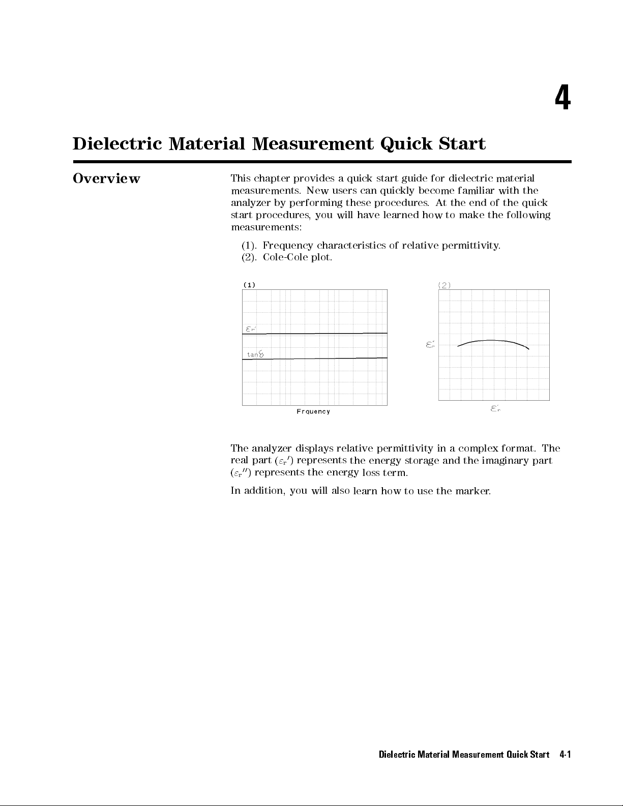
4
Dielectric
Overview
Material Measurement
This chapter
measurements.
analyzer by
start procedures
provides a
New users
performing
,you
quick start
can quickly
these
will
have
measurements:
(1). Frequency
(2).
Cole-Cole
characteristics of
plot.
Quick Start
guide
for
dielectric
become
procedures
learned
relative
.
how
familiar
At
the
to
make
permittivity
end
material
with
of
the
the
following
.
the
quick
The
analyzer displays
real
part
(
00
(
)
"
r
In
addition,
"
represents
0
)
represents
r
the
you
will
relative
the
energy
also
permittivity
energy
loss
learn
term.
how
storage
to
use
in
and
the
a
complex
the
marker
format.
imaginary
.
The
part
Dielectric Material Measurement Quick Start 4-1
Page 62

Brief Measurement
Theory
The
permittivity measurement
analyzer
dielectric
can measure
material.
setup is
shown in
relative permittivity
Figure 4-1
of a
plate shaped,
. The
solid
Note
The
analyzer
admittance
Where
,
_
"
r
_
Y
m
"
o
d
S
Figure
.
The
relative
measured
permittivity
height
area
4-1.
calculates
calculation
_
Y
_
"
m
=
r
j!
"
permittivity
admittance
of
MUT
of
lower
Dielectric
the
relative
d
S
o
of
free
electrode
Material
equation
space
Measurement
permittivity
is:
from
the
measured
The above equation is ideal, in fact, the equation in which the edge
eect
and parastic error of test xture is condidered is used. F
detail, refer to
Operation Manual
.
or
4-2 Dielectric Material Measurement Quick Start
Page 63

Basic Measurement
Flow
Figure
4-2 shows
the basic
ow for
a dielectric
material measurement.
Figure 4-2.
Basic Flow for Dielectric Material Measurements
Dielectric Material Measurement Quick Start 4-3
Page 64

Required Equipment
T
o
perform
required:
all the
steps in
this quick
start, the
following equipment
is
4291B
High
RF Impedance/Material
Impedance T
Calibration
16453A
Load
Dielectric Material
(Included with
Tweezers
Material
Under T
est Head
Kit
16453A)
(Included with
est (MUT)
Analyzer
Test
Fixture
16453A)
The
W
arning
16454A has
measurement
scalding
4-4 Dielectric Material Measurement Quick Start
Figure
the
capability
in environmental
when handling
4-3. Required
for
0
testing. Use
heated parts
Equipment
to
55
C
.
200 C
globes
temperature
to
prevent
Page 65

1.
P
ower
ON
Note
V
erify both
before
1.
Press the
After
installed
displayed.
Only
the
they
are
rear
panel.
the test
you turn
ON the
LINE switch.
the power-on
options and
option
numbers
installed).
station and
analyzer.
the test
If necessary
self-test (approximately
the connected
for
001
and
002
Other
installed
option
head are
, see
test head
are
displayed
numbers
correctly setup
Chapter 2.
10 seconds),
information are
at
power-on
are
listed
the
on
(if
the
2. Calibration
After turning
to stabilize
on the
the instrument.
Calibration denes
test head.
ON.
After
measurement
calibration
Calibration
calibration,
accuracy
kit
are
analyzer
the
measurement
must
the
.
The
required.
,
a
30
be
performed
analyzer
0
S,
minute-warm-up
accuracy
when
can
measure
0
,
and
50
period
at
the
APC-7
the
analyzer
within
its
terminations
is
required
R
on the
is
turned
specied
in
the
Figure 4-4. Calibration
Dielectric Material Measurement Quick Start 4-5
Page 66

Calibration Procedure
1.
2.
3.
4.
Press
Press
Turn
Figure
V
erify
Figure
5
.
4
Cal
N
NN
NN
NN
NN
N
N
N
N
N
N
N
N
N
N
N
CALIBRATE
the
APC-7
4-5
.
that
the
4-6
.
NN
NN
NN
NN
NN
NN
NN
N
N
N
N
MENU
R
connector
connector
N
N
N
N
N
N
.
on
the
test
head
as
sleeve
is
extended
shown
fully
as
in
shown
in
5.
Connect
in
Figure
Figure
the
4-7
4-5.
0
S
termination
.
to
the
APC-7
Figure
R
connector
4-6.
Figure 4-7.
NNNNNNNNNNN
6. Press
OPEN
NNN
.
After an OPEN calibration sequence of about 1 minute,the
softkey label is underlined.
as
shown
NNNNNNNNNNNNNN
OPEN
7. Disconnect the 0 S termination.
4-6 Dielectric Material Measurement Quick Start
Page 67

8.
Connect the
in
Figure 4-8
0
termination on
.
the APC-7
R
connector
as shown
9.
Press
After
softkey
10.
Disconnect
11.
Turn
shown
12.
V
Figure
erify
N
NN
N
N
N
N
N
SHORT
a
SHORT
label
only
in
that
4-10.
Figure
N
N
N
N
N
N
N
N
N
.
is
the
the
Figure
the
4-8.
calibration
underlined.
0
termination.
R
4-9
.
APC-7
connector
sequence
connector
sleeve
of
about
nut
of
the
is retracted
1
minute
50
termination as
fully
as
,
the
shown
N
N
N
N
N
N
N
N
N
N
N
SHORT
in
N
N
N
N
N
N
Figure 4-9. Figure 4-10.
13. Connect the 50 termination on the APC-7
in Figure 4-11.
Dielectric Material Measurement Quick Start 4-7
R
connector as shown
Page 68
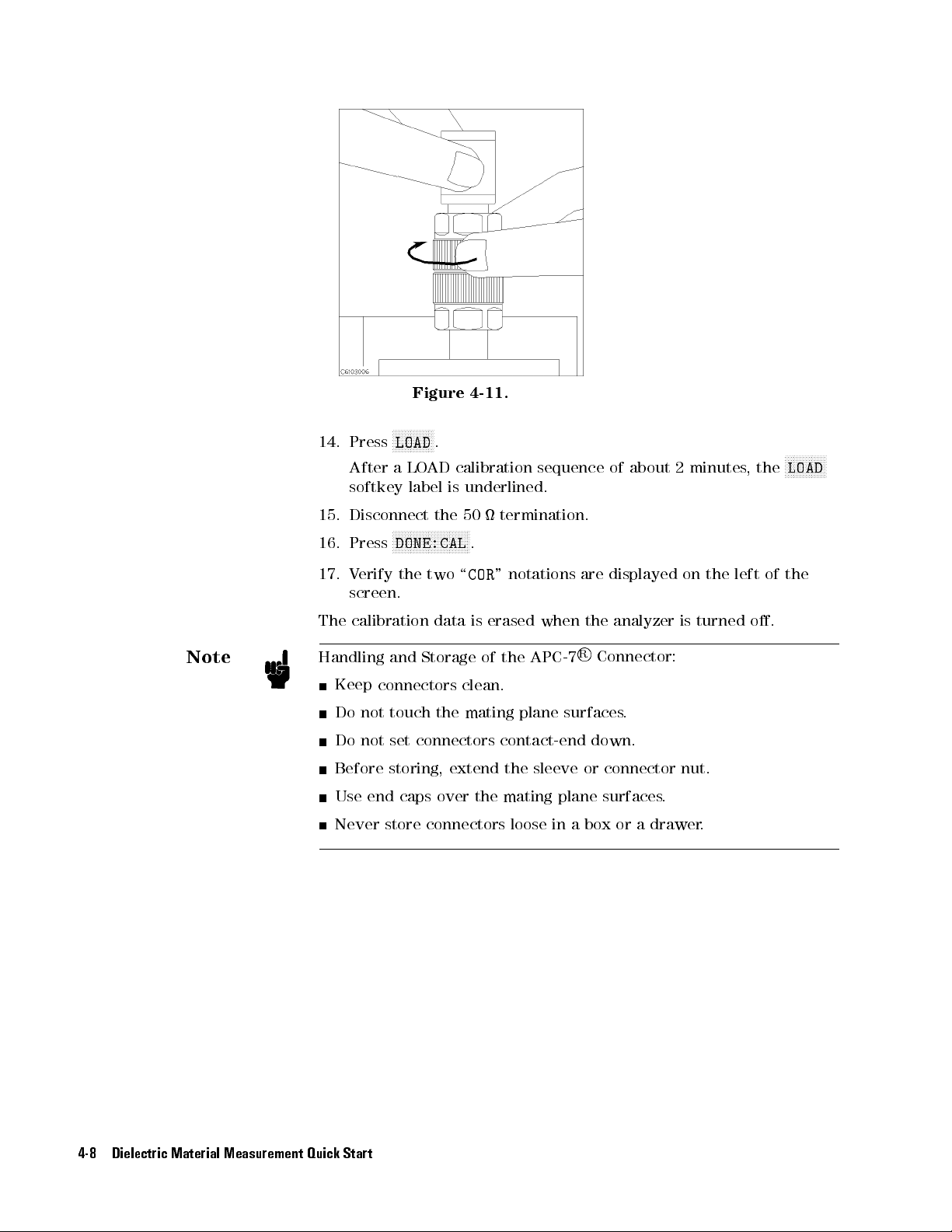
Note
14.
Press
After a
softkey
15.
Disconnect
16.
Press
17.
V
erify
screen.
The
calibration
Handling
Keep
Do
not
Do
not
Figure
N
N
N
N
N
N
N
N
N
N
N
N
N
N
LOAD
.
LO
AD
label
the
N
N
N
N
N
N
N
N
N
N
N
N
N
N
N
N
N
N
DONE:CAL
the
two
data
and
Storage
connectors
touch
the
set
connectors
4-11.
calibration
is
underlined.
50
NN
N
N
N
N
termination.
NN
.
\
COR
"
is
erased
of
the
clean.
mating
contact-end
sequence
notations
when
APC-7
plane
of
are
displayed
the
analyzer
R
Connector:
surfaces.
down.
about
2
minutes
on
the
is
turned
,
left
the
o.
of
N
N
N
N
N
N
N
LOAD
the
N
N
N
N
N
N
N
Before
Use
Never store
4-8 Dielectric Material Measurement Quick Start
storing,
end
extend
caps
over
the
connectors loose
the
sleeve
mating
plane
in a
or
connector
surfaces
box or
nut.
.
a drawer
.
Page 69
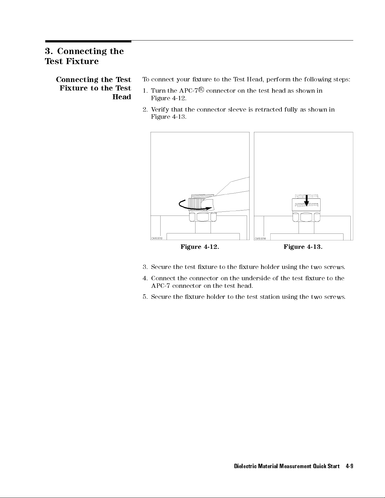
3.
Connecting
T
est Fixture
Connecting the
Fixture
to the
the
Test
Test
Head
T
o connect
1.
Turn
Figure
2.
V
erify
Figure
your xture
the
APC-7
4-12
.
that
the
4-13.
to the
R
connector
Test
on
connector sleeve
Head, perform
the
test head
is retracted
fully as
the following
as shown
shown
steps:
in
in
3.
Secure
4.
Connect
APC-7
5.
Secure
Figure
the
test
the
connector
connector
the
xture holder
4-12.
xture
on
the
to
on
the
the
test
to the
xture
underside
head.
test station
holder
of
Figure
using
the
the
test
using the
4-13.
two screws
xture
two
to
screws
.
the
.
Dielectric Material Measurement Quick Start 4-9
Page 70

P
Selecting
the
T
est
Fixture
erform the
1.
Press
2.
Press
After
you
dielectric
4-10 Dielectric Material Measurement Quick Start
Figure
following steps
5
4
Meas
N
N
N
N
N
N
N
N
N
N
N
N
N
N
N
N
N
N
N
N
N
N
N
NN
NN
NN
FIXTURE
N
N
N
N
NN
4-14.
Connecting
N
N
N
N
N
N
N
N
N
N
N
N
N
PERMITTVTY
to
select
N
N
N
N
NN
NN
NN
N
N
N
N
N
N
N
N
N
RETURN
select
the 16453A
as
a
test
material measurement mode
N
N
N
N
N
the
the
N
N
N
N
N
NN
NN
NN
16453
xture
.
T
est
16453A
N
N
N
N
N
N
N
N
N
N
,
the
Fixtures
as
the
analyzer
test
xture:
is
set
to
the
Page 71

4.
Input
Thickness
Load
Before
value
1.
Press
2.
Press
3.
Press
4.
Press
5.
Input
key.
6.
Press
7.
Press
8.
V
N
N
N
COMPEN
The
is
by
do
power
for
memory
xture compensation,
. The
load thickness
N
NN
NN
NN
NN
NN
NN
N
N
N
N
N
N
N
COMPEN
5
4
Cal
N
NN
NN
NN
NN
N
N
N
N
N
MODIFY
N
N
N
N
N
N
N
N
N
N
N
N
N
N
DEFINE
N
N
N
N
N
N
N
N
N
N
NN
NN
THICKNESS
the load
N
N
N
NN
NN
NN
NN
N
N
N
STD
DONE (DEFINED)
N
NN
N
N
N
N
N
N
N
N
N
N
N
KIT
DONE
erify
that
N
N
N
N
N
N
N
N
NN
KIT
need
back
is
the
N
N
N
N
N
N
thickness
o.
lost.
N
N
N
N
N
N
N
N
N
N
load
turned
performing
not
approximately
N
N
N
N
NN
N
N
N
N
N
N
N
N
N
N
N
N
NN
NN
NN
NN
NN
[TEFLON]
NN
NN
NN
NN
N
N
N
N
N
N
N
N
STANDARD
N
N
N
N
N
N
N
N
N
N
N
N
N
.
thickness value
N
N
N
N
N
N
N
N
N
N
N
N
NN
NN
N
N
N
N
NN
NN
NN
NN
N
N
N
N
(MODIFIED)
second
N
N
N
N
N
N
N
N
N
N
N
N
N
N
N
N
[TEFLO*]
However
the
to
input
on.
However
you need
value is
N
N
N
N
N
N
NN
NN
NN
NN
KIT [TEFLON]
NN
N
N
N
N
N
N
N
N
N
N
N
N
N
N
N
N
N
N
N
N
NN
NN
NN
NN
N
N
N
N
N
N
N
N
N
N
N
N
N
N
N
N
N
N
N
N
N
N
soft
NN
N
N
N
N
N
N
N
N
N
N
N
.
value
,
following
the
72
hours
NN
NN
N
N
.
NN
.
N
N
N
N
NN
NN
will
it
load
,
N
N
N
N
N
N
N
NN
NN
can
if
N
N
NN
N
N
key
or
written on
N
N
N
N
N
N
N
N
. Then,
N
.
N
N
N
N
.
be
be
procedure
thickness
the
more
to input
NN
NN
NN
N
.
from
lost
when
saved
analyzer
,
the
the case
press the
bottom
the
to memory
.
If
you
value
has
load
the load
unit
is
analyzer
do
this
when
been
thickness
thickness
of the
terminator
in the
,
you
you
turn
turned
value
load.
analyzer
o
in
Note
Note
N
N
N
N
N
N
N
N
N
N
N
N
N
N
N
N
N
N
N
N
N
N
NN
N
N
N
N
N
N
N
N
N
N
N
N
N
N
N
N
N
N
N
N
N
N
N
NN
N
N
N
N
N
N
N
N
N
N
N
N
N
N
N
Press
Press
V
erify
Press
load
COMPENKIT
N
N
N
N
N
N
N
N
N
N
N
N
N
N
N
USER
N
N
USER
that
NN
N
N
N
N
N
N
N
N
N
N
N
N
N
RETURN
thickness
. When
using
a
9.
10.
11.
12.
The
typical value
the
load
The load is made of the teon whose relative permittivity is 2.1. The
relative permittivity value has already memoried
[TEFLO*]
N
N
N
N
N
NN
NN
N
N
KIT
.
N
N
N
N
N
N
N
N
N
N
NN
NN
N
N
N
N
N
N
N
N
N
KIT
N
N
N
N
N
.
value
you need
micrometer
N
N
softkey
that
is
more accurate
or
calipers
NN
N
N
N
SAVE
label
N
USER
is
.
N
N
written on
N
N
N
N
N
N
N
N
N
N
N
N
N
N
N
N
N
N
N
NN
KIT
underlined.
the label
measurements,
N
N
N
.
on the
in the analyzer
case is
measure
a
.
Dielectric Material Measurement Quick Start 4-11
Page 72

5.
Fixture
Compensation
Note
P
erforming
Compensation
SHORT
Fixture
test
the
factor
requires
The
maximum
compensation corrects
xture electrode
measurement
. Fixture
OPEN, SHORT
pressure
as
and the
accuracy
compensation for
and LO
to
sandwich
much
as
the
possible
the parasitic
test head
is specied)
APC-7
and also
dielectric material
AD compensations
MUT
is
adjustable
.
error existing
R
connector
calculate edge
measurements
.
.
It
should
between the
(where
eect
be
at
1.
V
erify
that
the
upper
electrodes are
making
and
contact.
SHORT Compensation
When the
press the
1.
Press
After
label
test xture
following front
NN
NN
NN
N
N
N
N
N
N
N
N
N
N
N
FIXTURE COMPEN
4
5
Cal
the
short
compensation
is
underlined.
is
N
N
N
N
N
N
N
N
NN
the
lower
K
ready
panel
NN
NN
N
N
N
N
ey
Sequence
for
the
keys:
NN
NN
NN
N
N
N
N
N
N
N
N
N
N
COMPEN MENU
sequence
short
compensation
NN
NN
NN
N
N
N
N
N
N
N
N
N
N
N
N
N
N
N
N
N
N
N
N
N
N
N
NN
NN
NN
N
N
N
N
N
SHORT
is
done
,
the
N
N
N
N
N
.
NN
sequence
N
N
N
N
N
N
N
N
N
N
N
SHORT
N
N
N
N
softkey
,
4-12 Dielectric Material Measurement Quick Start
Page 73

Performing
Compensation
OPEN
1.
Pull
up
the
knob
. 2.
Press the
the knob
latch
button
while
pulling
up
.
3.
Release
the
knob
so
that
the
knob
is
latched.
OPEN Compensation
Key
Sequence
When the test xture is ready for the open compensation sequence
press the following front panel keys:
NNNNNNNNNNNNN
1.
Press
After the open compensation sequence is done
label is
N
OPEN
.
underlined.
,the
NN
NNNNNNNNNNNN
OPEN
softkey
Dielectric Material Measurement Quick Start 4-13
,
Page 74

Performing
Compensation
LOAD
1.
Place
the
MUT
on
the lower
electrode.
2.
Don't
touch
the
load
to
the
xture
body
.
3.
Pull up
LOAD Compensation K
When the test xture is ready for the load compensation sequence
press the following front panel keys:
1.
Press
After the load compensation sequence is done
label is
2. Press
Note
Don't force the upper electrode in a lateral direction.
4-14 Dielectric Material Measurement Quick Start
the
knob
to
release
NNNNNNNNNNNNN
N
LOAD
.
underlined.
NNNNNNNNNNN
NNNNNNNNNNNNNNNNNNNNNNNNN
DONE: COMPEN
the
latch.
ey Sequence
NN
4.
Press
down
MUT
between
the
knob
lightly
proper
contacts between
stabilize the
the
the
MUT.
knob
electrodes
once
, the
to
sandwich
.
to
Then
ensure
more
electrodes and
NN
NNNNNNNNNNNN
LOAD
the
press
to
,
softkey
Page 75

6.
Input
Thickness
7.
Placing
in
the
T
est
the
the
Fixture
MUT
MUT
Before
your
you measure
MUT.
applicable
diameter
be
at to
1.
Press
2.
Input
key
.
3.
Press
How
to
place
the permittivity
Measure the
MUT
thickness
must be
contact the
N
N
N
NN
NN
MATERIAL
5
4
Meas
the
thickness
NN
NN
N
N
N
N
N
N
N
N
N
N
N
N
N
N
N
N
N
N
thickness using
longer than
MUT to
NN
NN
N
N
N
N
N
N
N
N
N
N
N
N
N
N
N
of
N
NN
NN
NN
N
N
N
N
N
N
N
N
N
N
N
DONE (MODIFIED)
the
MUT
to
must be
15 mm.
the entire
N
N
NN
NN
NN
NN
N
N
N
SIZE
your
N
N
N
N
N
N
N
.
the
16453A
,you
less than
N
N
N
NN
NN
NN
NN
N
N
N
N
N
N
THICKNESS
MUT
.
Then
is
must input
calipers or
3mm.
The surface
surface of
N
N
N
N
N
N
N
N
N
N
N
N
N
N
.
press
shown in
the thickness
a micrometer
The MUT
of the
electrodes
the
unit
terminator
below.
MUT
.
of
.The
width or
must
Note
Note
1.
Sandwich
electrodes
load
during
After
to
ensure proper
MUT
.
If the thickness of the MUT is changed with
the
in
the
pulling
MUT
between
the
same
way
LO
AD
compensation.
down
the
contacts between
the
you placed
knob
,
push
the
down
electrodes
the
knob
lightly
and
to
stablilize
respect to pressure
once
more
the
,a
measurement error might occur if the applied pressure is not set at
maximum. Small spaces (gaps) between the electrodes and the MUT
could lead to measrement error
. The data required when applying
maximum pressure is dened by the specication.
Dielectric Material Measurement Quick Start 4-15
Page 76

8.
Setting
Analyzer
up
the
Before
match
setup
you start
your measurement
procedures
Frequency
Cole-Cole
The
setup procedure
following
procedure
pages
.
the measurement,
requirements.
for
the following
characteristics of
Plot
for each
.
Set up
your analyzer
you must
This section
measurements:
0
-tan
"
r
measurement is
according to
set up
the analyzer
provides the
described in
the
to
the
applicable
4-16 Dielectric Material Measurement Quick Start
Page 77

8-1. Setting
0
"
-
r
Frequency
up for
tan
vs.
The
example
T
able
setup
for
this
4-1.
MEASUREMENT
measurement
Block
is
as
P
arameter
follows.
Setting
Parameter
F
ormat
Table
Sweep
Sweep
Frequency
OSC Level
T
o
set
up
the
following
MEASUREMENT
1.
2.
3.
4.
STIMULUS
5.
6.
4
Meas
4
Meas
4
F
o
4
F
o
4
Sweep
4
Sw
rmat
rmat
eep
procedure:
5
4
Chan 1
5
4
Chan
5
4
5
4
N
N
N
SWEEP
5
N
N
N
SWEEP
5
4-2. STIMULUS
P
arameter
Type
Range
analyzer
Chan
Chan
Block
N
N
N
N
N
N
N
N
N
N
N
N
Block
NN
NN
N
N
N
N
PRMEABLTY
5
N
N
N
N
N
N
N
N
LOSS
5
2
N
N
N
N
LIN
5
1
N
N
N
N
LIN
5
2
N
N
N
N
N
N
N
N
N
N
NN
N
N
N
MENU
N
N
N
N
N
NN
NN
N
N
N
N
N
N
MENU
,
press
N
N
N
N
N
N
N
N
N
N
N
N
N
N
N
N
N
N
N
N
N
N
N
N
N
N
N
N
N
N
N
N
N
N
N
N
N
N
N
N
N
N
NN
N
N
N
N
N
NN
NN
N
TNGNT
N
N
N
N
N
N
N
N
N
N
Y-AXIS
N
N
N
N
N
N
N
N
NN
Y-AXIS
N
N
N
N
N
N
N
N
SWP
N
N
N
N
N
N
N
N
LOG
Channel
the
NN
NN
N
N
N
N
N
N
N
N
N
N
N
N
N
N
N
N
1 Setting
0
"
r
Linear Linear
NN
N
N
N
N
N
N
NN
N
N
N
N
N
N
N
N
N
N
N
SRC:
N
N
front
N
N
N
N
N
N
N
N
REAL
N
N
N
N
N
N
N
N
(tan
N
N
N
N
N
N
N
N
N
N
N
N
N
N
N
NN
Block
N
N
N
N
N
N
N
N
N
N
N
N
N
N
NN
(
N
NN
NN
N
N
N
N
N
FREQ
panel
NN
NN
NN
"
r
N
N
N
N
N
N
N
N
N
N
N
N
N
N
P
N
N
0
)
N
N
N
arameter
Frequency
1
MHz
500 mV
N
N
N
N
N
Channel
Log
to
1
keys
(Ch1
(Ch2
(Ch1
(Ch2
(Sweep
(Sweep
2 Setting
tan
Setting
GHz
as
shown
P
arameter
P
arameter
F
ormat
F
ormat
=
Type
in
the
=
"
r
=
tan
=
Linear)
=
Linear)
Frequency)
=
Log)
0
)
)
Note
7.
8.
9.
The
selected.
When some material which has large value of
the measurement
measurement error
5
4
Sta
4
Stop
4
Source
OSC level
5
4
1
rt
5
5
4
1
N
5
5
4
M/
5
4
G/n
N
N
N
N
N
N
N
N
N
N
N
NN
NN
NN
NN
N
N
N
N
N
N
N
N
N
5
5
5
OSC
LEVEL
sweep and
circuit occasionally oscillates over 1 GHz, the
may be increased.
4
4
0
.
dc
bias
5
4
4
5
x1
sweep
Dielectric Material Measurement Quick Start 4-17
(option
(Start
(Stop
(OSC
=
1
MHz)
=1
GHz)
Level
=
001)
can
be
is measured, since
"
r
500
also
mV)
Page 78

Display Annotations
The
settings
LCD
as annotations
they
are set
1
measurement
2
measurement
3
stimulus
4
stimulus
5
OSC
6
CW
7
dc
8
grid
T&B
The
The
z
/
The
The
xx
that
correctly.
start
stop
level
value
frequency
bias
value
scale
(you
x,
y
(for
value
value
REF
xx
scale/div
value
.
you set
. The
parameter
parameter
value
value
(OSC
(option
do
log,
of
the
of
the
(for
linear
value
of
the
in the
annotations are
for
for
(frequency
Level,
001
only)
not
have
linear
format)
top
of
grid
bottom
format)
is
z
.
reference
previous section
described below
channel 1
channel 2
,
dc
bias
sweep
dc
bias
sweep
set
the
scale
in
is
x
.
of
grid
is
y
.
position
at
which
are displayed
only)
only)
the
previous
the
7
.V
erify that
section).
9
locates is
on the
The
Note
analyzer
measurement and display of the data. The traces and
two channels are displayed, one over the other
4
5
Chan 2
activated. All the channel specic functions that are selected apply
to the active channel. When you want to display the trace of
channel 1 or 2, toggle
and then select
Jump to \9. Measuring the MUT"
4-18 Dielectric Material Measurement Quick Start
has
two channels
keys (in the A
4
Chan 1
that provide
independent
grids of the
5
.The
4
Chan
and
1
CTIVE CHANNEL block) select which channel
NNNNNNNNNNNNNNNNN
NNNNNNNNNNNNNNNNNNNNNNNNN
DUAL CHAN ON off
Chan 2
5
5or4
NNNNNNNN
to
NNNNNNNNNNNNNNNNN
on OFF
NNN
under
either
4
Display
is
5
,
Page 79

8-2. Setting
Cole-Cole
up for
Plot
a
The
example setup
T
able 4-3.
for this
MEASUREMENT Block
measurement is
as follows
Parameter
.
Setting
T
able
Sweep
Sweep Type
Frequency
OSC
T
o
set
up
the
following
MEASUREMENT
1.
2.
STIMULUS
3.
4.
4
Displa
4
Chan
4
Sw
4
Sw
eep
eep
procedure:
N
DUAL
5
y
5
4
1
N
N
N
SWEEP
5
N
N
N
SWEEP
5
P
F
4-4.
P
arameter
Range
Level
analyzer
N
N
N
N
N
N
N
NN
NN
NN
N
N
5
F
o
rmat
Block
NN
N
N
N
N
N
N
N
N
N
N
N
N
N
N
N
N
NN
N
N
N
N
N
N
N
N
N
N
arameter
ormat
STIMULUS
,
press
Block
N
N
N
N
N
N
N
N
N
N
N
N
N
N
N
N
N
CHAN
N
N
SOURCE
N
N
TYPE
NN
ON
N
N
N
N
N
N
N
N
N
N
NN
NN
NN
COMPLEX
N
N
N
N
N
N
N
N
NN
N
N
N
N
N
N
N
N
N
N
N
N
N
N
N
N
N
N
N
N
LIN
the
front
NN
NN
N
N
N
N
N
N
N
N
N
N
N
off
NN
N
N
N
N
N
N
N
N
N
N
N
N
N
N
N
N
PLANE
N
N
NN
N
N
N
N
N
N
N
N
N
N
N
N
N
N
FREQUENCY
N
N
NN
N
N
N
Channel 1
Block
N
NN
NN
NN
N
N
N
N
N
N
N
N
N
N
0
"
-
"
r
r
Complex
P
arameter
Frequency
Linear
1
MHz
500
panel keys
(Dual
(Ch1
Plane)
N
N
N
NN
(Sweep
(Sweep
Setting
00
Plane
to
10
MHz
mV
as shown
Channel OFF)
F
ormat
Setting
=
=
Frequency)
Type
=
in
the
Complex
Linear)
5.
4
Sta
rt
6.
4
Stop
7.
4
Source
N
N
N
N
N
N
N
N
N
N
NN
NN
NN
N
N
N
N
N
N
other
COMPLEX
N
N
N
N
N
N
N
to avoid
.
When
N
DUAL CHAN
selected
the
5
4
1
5
4
1
5
N
NN
NN
NN
N
N
N
N
N
N
5
5
4
M/
5
5
4
4
0
M/
N
N
N
N
N
NN
NN
N
N
N
N
N
N
OSC
LEVEL
NN
N
N
N
N
N
N
N
N
N
N
N
N
N
N
PLANE
NN
NN
NN
N
N
N
N
N
N
N
N
N
N
ON off
displaying the
5
N
N
N
N
N
N
N
N
N
N
N
N
N
N
N
NN
NN
NN
NN
N
N
N
N
N
or
N
N
5
5
4
5
is
N
N
N
N
NN
SPLIT DISP
5
4
4
0
0
selected
NN
NN
N
N
N
N
N
N
N
N
N
N
N
two dierent
N
N
N
4
k/m
N
N
N
as
N
N
5
the
NN
NN
NN
N
N
N
on OFF
N
(Start
(Stop
(OSC
format, the
N
N
N
N
N
N
N
N
N
N
N
N
N
N
under
format
=1
=
10
Level
4
Displa
traces
MHz)
MHz)
=
5
y
,
500
mV)
should
one
be
over
Dielectric Material Measurement Quick Start 4-19
Page 80
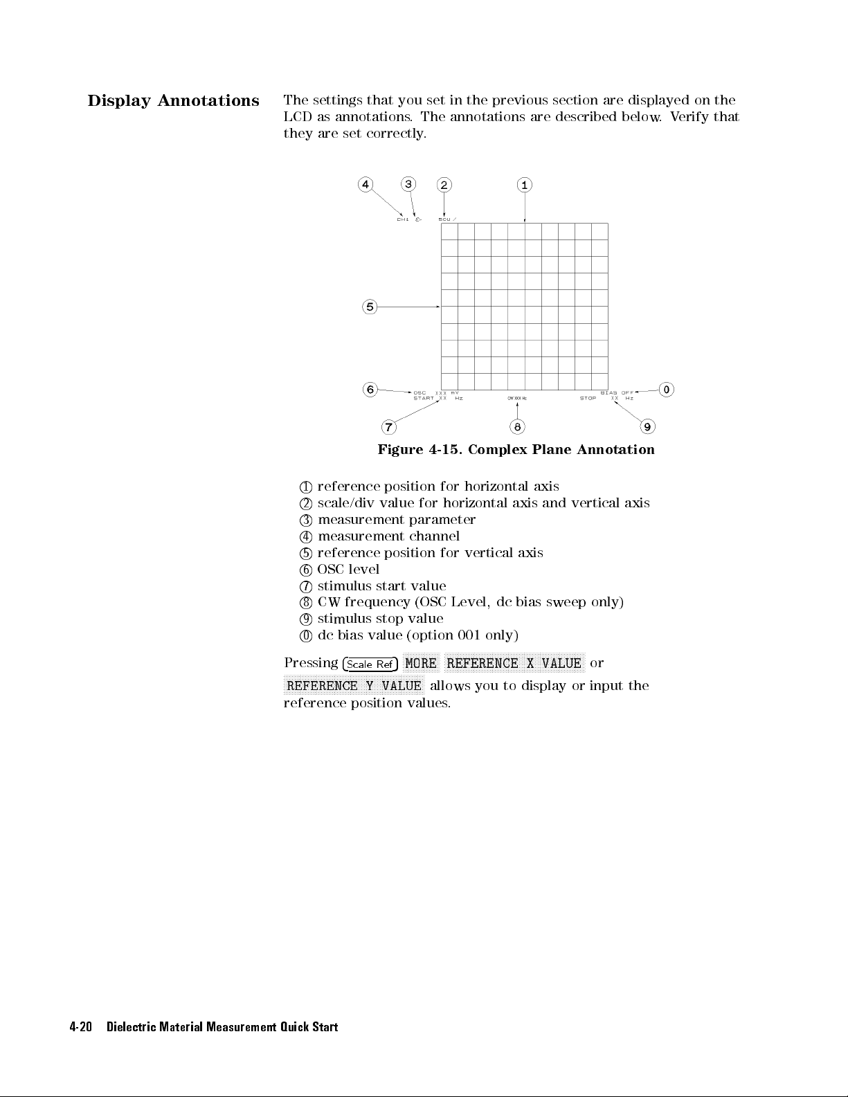
Display Annotations
The
settings
LCD
as annotations
they
are set
that
you set
. The
correctly.
in the
previous section
annotations are
are displayed
described below
.V
erify that
on the
1
reference
2
scale/div
3
measurement
4
measurement
5
reference
6
OSC
7
stimulus
8
CW
9
stimulus
0
dc
bias
Pressing
N
N
N
N
N
N
N
4
N
N
N
N
N
N
N
N
N
N
N
N
NN
NN
REFERENCE
reference
Figure 4-15.
position
value
position
level
start
frequency
stop
value
N
N
N
N
N
N
Y
Ref
N
N
N
N
N
N
N
VALUE
5
N
N
N
N
N
Scale
NN
N
position
for
for
horizontal
parameter
channel
for
value
(OSC
Level,
value
(option 001
NN
NN
NN
MORE
NN
NN
NN
NN
N
N
N
N
N
N
N
N
REFERENCE X
NN
N
N
N
NN
allows
values
.
Complex Plane
horizontal
vertical
axis
axis
axis
dc
bias sweep
and
only)
N
N
N
N
N
N
N
N
N
N
N
N
N
N
N
N
N
NN
NN
NN
NN
N
N
N
N
N
N
N
N
VALUE
you
to
display
Annotation
vertical
N
N
N
N
N
N
N
N
N
NN
NN
N
or
only)
or
input
axis
the
4-20 Dielectric Material Measurement Quick Start
Page 81

9.
Measuring
MUT
the
After
you place
displayed.
the MUT
on the
test xture
, the
measured result
is
P
erforming A
Using the
utomatic
Scaling
Marker
Often,
too
scaling
1.
2.
3.
Y
chapter
If
ou
you
large
Press
Press
Press
will
the
or
function,
4
Chan
4
Scale
N
N
N
N
AUTO
get
.
want
rotary knob
Marker
frequency
(for
functions allow
.
example
procedure
for
a
Specic
for
a
specic
Marker
1.
Press
for
4
Ma
trace
obtained
too
small
for
you
can
5
or
4
Chan
1
5
.
Ref
NN
NN
NN
N
N
N
N
N
N
N
N
N
N
N
N
N
N
N
N
N
N
N
NN
N
the
to
or
SCALE
change
input
to scale
measurement
scale
scale
you
They
also
allow
,
the
maximum,
shows
P
oint"
you
how
in
Chapter
point.
Frequency/OSC
5
.
rk
er
after
the
obtain
5
to
2
,
value
to
specifying
grid.
the
activate
the trace
results
press
to
read
you
to
the
read
6
Level/dc
However
optimum
the
of selected
shown
4
Scale
Ref
as
required.
out
the
move
the
minimum,
a
measured
for
information
the
frequency
,
by using
scale
setting.
required
channel.
channel.
on
the
rst page
N
N
N
N
N
N
N
N
N
N
N
NN
NN
NN
NN
N
SCALE/DIV
5
trace
N
values
marker
or
the
peak
value
.
on
bias
Characteristics
range is
the automatic
of this
N
N
N
N
N
N
N
N
and
turn
and
the
to
a
specic
point).
See
\Searching
how
to
search
the
point
This
2.
Turn
the
3.
you
Read
want
the
rotary
marker
to
knob
read
the measured
value displayed
until
1Marker value for channel 1
2Marker value for channel 2
3Marker stimulus for channel 1
4Marker stimulus for channel 2
the
marker
value.
on the
moves
upper
to
right
the
point
of
the
where
display
.
Dielectric Material Measurement Quick Start 4-21
Page 82

Marker
for a
Cole-Cole Plot
1.
Press
4
2.
Turn the
you
want to
3.
Read the
1
Marker value
2
Marker value
3
Marker stimulus
5
.
Ma
rker
rotary
read
marker value
knob
the
for
horizontal
for
vertical
until
the
measured
displayed
position
marker
value
on
position
.
the
(Y
moves
upper
(X
axis)
axis)
to
right
the
point
of
the
where
display
.
10. Measuring
Other
For
MUT
More
s
Information
If
you
want
Placing
size
Chapter
,
start
the
from
6
provides
measurement
applying
dc bias
to
measure
MUT
in
\6.
techniques
other
the
T
est
Fixture
Input
the
procedures
(for
MUT
s
on
".
MUT
Thickness".
for
the
example
, saving/recalling, and printing).
dierent
If
the
next
analyzer's
,
averaging,
setups
,
MUT
is
key
features
monitoring
start
a
dierent
from
and
level,
\7.
4-22 Dielectric Material Measurement Quick Start
Page 83
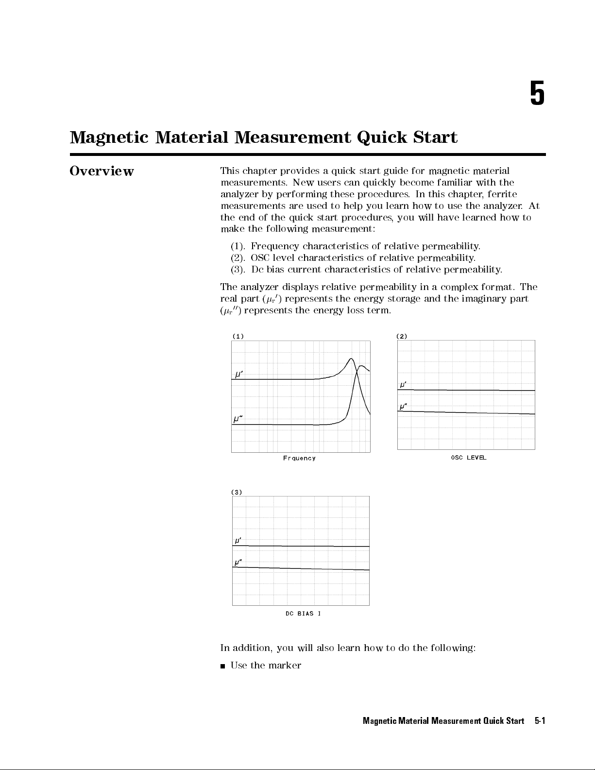
5
Magnetic
Overview
Material Measurement
This
chapter
measurements
analyzer
measurements
the
end
make the
(1). Frequency
(2).
OSC
(3).
Dc
The
analyzer
real
part
00
(
)
represents
r
provides
by
performing
of
the
.
New
are
quick start
users
used
a
quick
these
to
help you
procedures,
following measurement:
characteristics of
level characteristics
bias
0
)
(
r
current
displays
represents
characteristics
relative
the
energy
the
Quick Start
start
guide
for
can quickly
procedures.
become familiar
In this
learn how
you will
relative permeability
of relative
permeability
energy
loss
term.
of
relative
storage
permeability
in
and
magnetic material
with the
chapter,
to use
have learned
ferrite
the analyzer
how
.
.
permeability
a
complex
the
imaginary
.
format.
.
The
part
At
to
In addition, you will also learn how to do the following:
Use the marker
Magnetic Material Measurement Quick Start 5-1
Page 84

Brief Measurement
Theory
The
permeability measurement
The
analyzer can
magnetic
material.
measure relative
signal ow
permeability for
is shown
in Figure
a toroidal
5-1.
shape
Figure
The
analyzer calculates
The
calculation formula
_
=
Where
,
_
_
Z
m
o
h
b
c
relative
measured
permeability
height
outer
inner diameter of MUT
5-1.
_
Z
m
j!
h
o
permeability
of
MUT
diameter
Magnetic
the
relative
is:
2
+
1
b
ln
c
impedance
of
free
(Material
of
MUT
Material
permeability
space
Under
Measurement
from
T
est)
the
impedance
.
5-2 Magnetic Material Measurement Quick Start
Page 85

Basic Measurement
Flow
Figure
5-2 shows
the basic
ow for
a magnetic
material measurement.
Figure 5-2. Basic Flow for Magnetic Material Measurements
Magnetic Material Measurement Quick Start 5-3
Page 86

Required Equipment
T
o
perform
required:
all the
steps in
this quick
start, the
following equipment
is
4291B
Low
RF Impedance/Material
Impedance T
Calibration
16454A
Fixture
MUT
Magnetic Material
Holder (Included
Holder (Included
Tweezers
Material
guide
Under T
.)
est Head
Kit
(Included with
est (MUT)
Analyzer
Test
Fixture
with 16454A)
with 16454A)
16454A)
(Ferrite
material
is
demonstrated
in
this
The
W
arning
16454A has
measurement
scalding
5-4 Magnetic Material Measurement Quick Start
Figure
the capability
in environmental
when handling
5-3.
Required
for
0
testing. Use
heated parts
Equipment
to
55
C
.
200 C
globes
temperature
to
prevent
Page 87

1.
P
ower
ON
Note
V
erify both
before
1.
Press the
After
installed
displayed.
Only
the
they
are
rear
panel.
the test
you turn
ON the
LINE switch.
the power-on
options and
option
numbers
installed).
station and
analyzer.
the test
If necessary
self-test (approximately
the connected
for
001
and
002
Other
installed
option
head are
, see
test head
are
displayed
numbers
correctly setup
Chapter 2.
10 seconds),
information are
at
power-on
are
listed
the
on
(if
the
2. Calibration
After turning
to stabilize
on the
the instrument.
Calibration denes
test head.
turned
specied
in
the
The
ON.
After
measurement
calibration
calibration
analyzer
the
measurement
the
calibration,
accuracy
kit
are
,
a
30
must
be
.
required.
minute-warm-up
accuracy
performed
the
analyzer
The
0
S,
0
at
when
can
,
the
and
period
APC-7
the
analyzer
measure
50
terminations
is
required
R
on the
within
is
its
Figure 5-4. Calibration
Magnetic Material Measurement Quick Start 5-5
Page 88

Calibration Procedure
1.
2.
3.
4.
Press
Press
Turn
Figure
V
erify
Figure
5
.
4
Cal
N
NN
NN
NN
NN
N
N
N
N
N
N
N
N
N
N
N
CALIBRATE
the
APC-7
5-5
.
that
the
5-6
.
NN
NN
NN
NN
NN
NN
NN
N
N
N
N
MENU
R
connector
connector
N
N
N
N
N
N
.
on
the
test
head
as
sleeve
is
extended
shown
fully
as
in
shown
in
5.
Connect
in
Figure
Figure
the
5-7
5-5.
0
S
termination
.
to
the
APC-7
Figure
R
connector
5-6.
Figure 5-7.
NNNNNNNNNNN
6. Press
OPEN
NNN
.
After an OPEN calibration sequence of about 1 minute,the
softkey label is underlined.
as
shown
NNNNNNNNNNNNNN
OPEN
7. Disconnect the 0 S termination.
5-6 Magnetic Material Measurement Quick Start
Page 89

8.
Connect the
in
Figure 5-8
0
termination on
.
the APC-7
R
connector
as shown
9.
Press
After
softkey
10.
Disconnect
11.
Turn
shown
12.
V
Figure
erify
N
NN
N
N
N
N
N
SHORT
a
SHORT
label
only
in
that
5-10.
Figure
N
N
N
N
N
N
N
N
N
.
is
the
the
Figure
the
5-8.
calibration
underlined.
0
termination.
R
5-9
.
APC-7
connector
sequence
connector
sleeve
of
about
nut
of
the
is retracted
1
minute
50
termination as
fully
as
,
the
shown
N
N
N
N
N
N
N
N
N
N
N
SHORT
in
N
N
N
N
N
N
Figure 5-9. Figure 5-10.
13. Connect the 50 termination on the APC-7
in Figure 5-11.
Magnetic Material Measurement Quick Start 5-7
R
connector as shown
Page 90

Note
14.
Press
After a
softkey
15.
Disconnect
16.
Press
17.
V
erify
screen.
The
calibration
Handling
Keep
Do
not
Do
not
Figure
N
N
N
N
N
N
N
N
N
N
N
N
N
N
LOAD
.
LO
AD
label
the
N
N
N
N
N
N
N
N
N
N
N
N
N
N
N
N
N
N
DONE:CAL
the
two
data
and
Storage
connectors
touch
the
set
connectors
5-11.
calibration
is
underlined.
50
NN
N
N
N
N
termination.
NN
.
\
COR
"
is
erased
of
the
clean.
mating
contact-end
sequence
notations
when
APC-7
plane
of
are
displayed
the
analyzer
R
Connector:
surfaces.
down.
about
2
minutes
on
the
is
turned
,
left
the
o.
of
N
N
N
N
N
N
N
LOAD
the
N
N
N
N
N
N
N
Before
Use
Never store
5-8 Magnetic Material Measurement Quick Start
storing,
end
extend
caps
over
the
connectors loose
the
sleeve
mating
plane
in a
or
connector
surfaces
box or
nut.
.
a drawer
.
Page 91

3.
Connecting
T
est Fixture
Selecting Fixture
the
and
Holder
16454A consists
applicable
T
able
MUT
5-1.
size
MUT
of two
for each
Size
xtures,
xture is
For
Test
a large
listed in
Fixtures
one and
Table
a small
5-1.
The
Fixture Small Large
Holder A B C D
one
.
The
MUT Outer
MUT
Inner
MUT
Height
Diameter (mm)
Diameter
(mm)
(mm)
Figure
5-12
3.1
shows
8mm
mm
3
mm
the
3.1
3
dimensions
6mm
mm
mm
of
the
MUT
20 mm
6
10
mm
holder
mm
20 mm
5
mm
10
mm
.
Connecting the
Fixture to the T
T
est
est
Head
Figure
T
o connect
your
1. Turn the APC-7
5-12.
Dimensions
xture
to
the
R
connector on the test head as shown in
Figure 5-13.
2. V
erify that the connector sleeve is
Figure 5-14.
of
the
MUT
Holder
T
est
Head,
perform
the
following
steps:
retracted fully as shown in
Magnetic Material Measurement Quick Start 5-9
Page 92

3.
Secure
4.
Connect
the
the
APC-7 connector
5.
Secure
the
Figure
test
connector
xture
5-13.
xture
on
holder
the
to
on
the
the
test
to
xture
underside
head.
the
test
holder
of
station
Figure
using
the
test
using
5-14.
the
xture
the
two
two
screws
to
the
screws
.
.
Figure 5-15. Connecting the T
5-10 Magnetic Material Measurement Quick Start
est Fixtures (16454A Small)
Page 93

Selecting the
Fixture
Test
P
erform the
1.
Press
2.
Press
following steps
N
N
N
N
NN
NN
NN
NN
NN
NN
NN
N
N
N
N
4
Meas
NN
NN
NN
5
NN
NN
N
N
N
N
FIXTURE
N
N
N
N
N
N
N
N
N
N
NN
NN
NN
NN
NN
NN
N
N
N
SELECT FIXTURE
to select
N
N
N
N
NN
NN
NN
NN
NN
NN
NN
N
N
N
N
N
PERMEABLTY
N
N
N
N
N
N
the 16454A
N
N
N
N
N
N
NN
N
as the
test xture:
4.
Fixture
Compensation
P
erforming
Compensation
SHORT
3. Select
T
o
the xture
small
large
N
N
N
NN
NN
NN
NN
4.
After
magnetic
Fixture
test
the
for
RETURN
Press
you
select
material
compensation reduces
xture
electrode
measurement
the
magnetic
compensation.
The
the
SHORT
test
Compensation
xture
that
you
are
N
N
N
N
N
N
N
N
N
the
16454A
as
measurement
and the
accuracy
test head
is specied).
material measurement
corrects
.
using.
Press
N
NN
N
N
N
N
N
N
N
N
N
N
N
FIXTURE
N
N
NN
NN
NN
N
N
N
N
N
N
16454(L)
a
test
xture
mode
.
the parasitic
APC-7
Fixture compensation
requires only
for
the
N
N
N
N
N
N
N
N
NN
NN
NN
N
N
N
N
N
N
N
N
N
N
N
16454(S)
N
N
N
N
N
N
N
N
N
N
N
N
, the
analyzer is
error existing
R
connector
residual
N
N
N
N
N
N
N
N
NN
N
between the
(where
the
SHORT
impedance
set to
due to
the
1. Remove the cap of the xture
. 2. Place nothing or a MUT holder only in
Magnetic Material Measurement Quick Start 5-11
the xture
.
Page 94

3.
Replace
the
cap by
screwing tightly
. :
5.
Input
Size
the
MUT
SHORT
When
press
1.
2.
1.
2.
3.
4.
5.
6.
7.
8.
Compensation
the
test
xture
the
following
N
NN
NN
NN
N
N
N
N
N
N
N
N
N
Press
After
softkey
Press
Press
Press
Input
Press
Input
Press
Input the height of your MUT (
Press
FIXTURE
5
4
Cal
the
SHORT
label
is
underlined.
N
N
N
N
N
N
N
N
N
N
N
N
N
N
N
N
N
N
N
NN
NN
N
N
N
COMPEN:DONE
4
Meas
N
N
N
N
N
N
N
N
N
N
N
INNER
the
inner
N
N
N
N
N
N
N
N
N
N
NN
OUTER
the
outer
N
N
NN
NN
NN
NN
NN
HEIGHT
NNNNNNNNNNNN
DONE (MODIFIED)
N
N
N
N
N
N
N
N
N
N
N
N
N
MATERIAL
5
N
N
N
N
N
NN
NN
N
N
N
N
N
N
N
DIAMETER
diameter
NN
NN
N
N
N
N
N
N
N
N
N
N
N
DIAMETER
diameter
NN
N
N
N
N
N
N
.
NNNNNNNNNNNNNNNNNNNNNNNNN
Key
is
ready
front
panel
N
N
N
N
N
N
N
N
N
N
NN
NN
NN
N
COMPEN
compensation
N
N
N
N
N
N
N
N
N
N
N
N
N
N
N
N
N
N
N
N
N
NN
N
N
SIZE
N
N
N
N
N
N
N
N
N
N
N
N
N
N
NN
N
N
N
N
N
N
N
N
N
NN
NN
NN
N
N
N
NNNNNNNNNN
Sequence
for
keys:
N
N
N
N
N
N
N
N
N
N
N
N
N
N
N
N
N
N
N
N
N
N
N
.
.
of
your
.
of
your
.
the
SHORT
N
NN
NN
NN
N
N
N
N
N
N
N
N
N
N
N
N
N
N
N
N
COMPEN
sequence
h
N
MENU
MUT
MUT
in Figure 5-16).
compensation
N
NN
NN
NN
NN
NN
N
N
N
SHORT
is
done
in
Figure
in
Figure 5-16
N
N
N
NN
(
c
(
b
sequence,
N
N
N
N
N
N
N
N
N
.
N
NN
N
N
N
N
N
N
N
N
N
N
N
N
N
N
SHORT
,
the
5-16
).
).
5-12 Magnetic Material Measurement Quick Start
Page 95

Figure 5-16.
Dimensions
of
the
MUT
6.
Placing
on
the
MUT
Outer
MUT
Inner
MUT
Height (mm)
the
MUT
T
est Fixture
MUT Size
For
T
est
Fixtures
Fixture Small Large
Holder A B C D
Diameter
Diameter
How
(mm)
(mm)
to
place
the
8
3.1
3mm
mm
mm
MUT
on
the
6
3.1
3mm
16454A
mm
mm
is
shown
20
mm
6
mm
10 mm
below:
20
10 mm
5
mm
mm
1. Remove the cap of the xture
. 2. Place a MUT on the MUT holder in the
Magnetic Material Measurement Quick Start 5-13
xture.
Page 96

3.
Replace
the
cap by
screwing tightly
. :
7.
Setting
Analyzer
up
the
Before
t
procedures for
you
your
measurement
start
the
the following
measurement,
Frequency characteristics
OSC level
Dc
bias
The
setup
following
procedure
characteristics of
current characteristics
procedure for
pages
.
Set
up
.
requirements
measurements:
0
of
r
0
-
r
of
each
measurement
your
analyzer
-
.
r
you
This
00
r
00
must set
section provides
0
00
-
r
r
is
described
according
up the
the
applicable
analyzer to
the setup
in
the
5-14 Magnetic Material Measurement Quick Start
Page 97

7-1. Setting
0
r
00
-
r
up for
vs
. Frequency
The
example setup
T
able 5-2.
for this
MEASUREMENT Block
measurement is
as follows
Parameter
.
Setting
P
arameter
F
ormat
T
able 5-3.
Sweep
Sweep Type
Frequency
OSC
T
o
set
up
the
following
MEASUREMENT
1.
2.
3.
4.
STIMULUS
5.
6.
4
Meas
4
Meas
4
F
4
F
4
Sw
4
Sw
o
rmat
o
rmat
eep
eep
procedure:
5
4
Chan 1
5
4
Chan
5
4
5
4
N
N
N
SWEEP
5
N
N
N
SWEEP
5
P
arameter
Range
Level
analyzer
N
PRMEABLTY
5
N
LOSS
5
2
5
Chan
1
5
Chan
2
Block
N
N
N
N
N
N
N
N
N
N
NN
N
N
N
N
N
N
N
N
N
N
N
N
N
N
N
N
NN
Channel 1
STIMULUS Block
,
press
the
Block
N
N
N
N
N
N
N
N
N
N
N
N
N
N
NN
NN
NN
N
N
N
N
N
N
N
N
N
N
N
N
N
N
REAL
N
N
N
N
N
N
N
N
N
N
NN
NN
NN
NN
N
N
N
N
N
N
N
N
N
N
N
N
N
N
N
N
(
NN
N
N
N
N
N
N
N
N
N
N
N
N
N
N
N
N
N
NN
N
N
N
N
N
N
N
N
N
N
N
N
N
N
N
N
N
N
N
N
N
NN
N
N
N
SRC:
N
N
N
N
N
N
N
N
N
N
N
N
N
N
N
LIN
N
N
N
N
N
N
LIN
N
N
N
N
N
N
N
N
MENU
NN
N
N
N
N
N
N
MENU
N
N
N
N
N
N
N
N
N
N
N
N
N
N
N
N
N
N
N
N
FACTR
N
N
N
N
N
N
N
N
NN
Y-AXIS
N
N
N
Y-AXIS
N
N
SWP
N
N
LOG
P
arameter
Frequency
1
MHz
500
keys
N
N
N
N
N
N
N
0
)
(Ch1
(Ch2
(Ch1
(Ch2
N
N
NN
N
(Sweep
(Sweep
Channel 2
Setting
Log
to
1.8
GHz
mV
as
shown
P
arameter
P
arameter
F
ormat
F
ormat
00
r
=
Type
Setting
0
r
Linear Linear
front
panel
N
N
N
N
N
NN
NN
NN
N
N
N
N
N
N
N
(
r
N
NN
NN
NN
NN
N
N
N
N
N
00
)
r
N
N
N
N
N
N
N
N
N
N
N
N
N
N
N
N
N
N
FREQ
Setting
in the
=
=
=
Linear)
=
Linear)
Frequency)
=
Log)
0
)
r
00
)
r
7.
8.
9.
When
001
Jump to \Display Annotations"
5
rt
you
5
4
1
N
N
N
N
OSC
5
want
in
4
M/
N
N
N
N
N
N
N
N
N
N
NN
LEVEL
to
Chapter
4
Sta
4
Stop54154.54854G/n
4
Source
Only)"
5
NN
NN
N
N
apply
5
N
N
N
N
N
N
N
5
5
4
4
0
.
dc
bias
6.
(Start
(Stop
to
\Applying
(OSC
5
5
4
4
5
x1
,
refer
Magnetic Material Measurement Quick Start 5-15
=
1
=
1.8
Level
Dc
Bias (Option
MHz)
GHz)
=
500
mV)
Page 98

7-2. Setting
0
00
-
r
vs
r
up for
.OSC
Level
The
example setup
T
able 5-4.
for this
MEASUREMENT Block
measurement is
as follows
Parameter
.
Setting
P
arameter
F
ormat
T
able 5-5.
Sweep
Sweep Type
OSC
Level
Source
T
o
set
up
the
following
MEASUREMENT
1.
2.
3.
4.
STIMULUS
5.
6.
procedure:
4
Meas54Chan
5
4
4
Meas
Chan
5
o
o
rmat
rmat
eep
4
5
4
N
N
SWEEP
5
N
NN
SWEEP
5
4
F
4
F
4
Sweep
4
Sw
N
STIMULUS Block
P
arameter
Range
Frequency
analyzer
Chan
Chan
Block
N
N
N
N
N
N
N
N
N
N
N
N
,
Block
NN
NN
N
N
N
N
N
N
N
PRMEABLTY REAL
5
1
N
N
N
N
N
N
N
N
N
N
N
LOSS
5
2
NN
N
N
N
N
N
N
LIN
5
1
N
N
N
NN
N
N
N
LIN
5
2
N
N
N
N
N
N
N
N
N
N
N
N
NN
N
N
N
N
N
MENU
N
N
N
N
N
N
N
N
N
N
N
N
N
N
N
NN
NN
MENU
press
N
N
N
N
N
N
N
N
N
N
N
N
N
N
N
N
N
NN
FACTR
N
N
N
N
N
N
N
N
Y-AXIS
N
N
N
N
N
N
N
N
Y-AXIS
N
N
N
N
N
N
OSC
N
NN
N
N
N
N
SWP
Channel 1
the
N
N
N
NN
NN
NN
N
N
N
N
NN
NN
NN
N
N
N
N
N
N
N
N
N
N
N
N
N
NN
NN
N
N
N
N
N
N
N
N
N
N
N
N
N
N
NN
N
N
N
N
N
N
N
N
N
N
N
N
N
N
LEVEL
N
N
N
N
N
N
N
N
N
N
N
N
N
TYPE:
P
arameter
OSC
Linear
200
mV
100
keys
N
N
N
N
N
N
0
)
(Ch1
(Ch2
(Ch1
(Ch2
(Sweep
N
N
N
N
N
(Sweep
Channel 2
Level
to
500
mV
MHz
as
P
arameter
P
arameter
F
ormat
F
ormat
Setting
0
r
Linear Linear
front
panel
N
N
N
N
N
N
N
N
N
N
N
N
N
N
N
NN
NN
NN
(
r
N
N
N
N
N
N
N
N
N
N
N
NN
NN
N
00
)
(
r
N
N
N
N
N
N
N
N
N
N
NN
N
N
N
N
N
N
N
N
N
N
N
N
N
N
NN
NN
N
N
N
N
N
N
N
N
LIN
Setting
00
r
Setting
shown
=
=
=
OSC
Type
in
the
=
=
Linear)
Linear)
Level)
=
Linear)
0
)
r
00
)
r
7.
4
Start
8.
4
Stop
9.
4
Source
When
001
Only)" in
Jump to \Display Annotations"
5-16 Magnetic Material Measurement Quick Start
5
5
4
4
0
5
5
4
4
0
N
NN
N
N
CW
5
you want
5
5
5
4
4
.
2
x1
5
5
5
4
4
.
5
x1
N
N
N
N
N
N
N
N
N
N
N
N
N
N
N
N
N
N
4
1
apply
5
FREQ
to
Chapter 6.
4
dc
(Start
=
200
mV)
(Stop
=
500
mV)
(CW
Freq.
=
100
5
5
4
M/
,
refer
5
to
\Applying
Dc
Bias
4
0
0
bias
MHz)
(Option
Page 99

7-3. Setting
0
-
r
(Option
00
r
001
up for
vs
. Dc-I
only)
The
example
Table
setup
for this
5-6. MEASUREMENT
measurement is
Block
as follows
P
arameter
.
Setting
P
arameter
F
ormat
T
able
Sweep P
Sweep
dc
Bias Range
OSC
Source
T
o
set
up
the
following
MEASUREMENT
1.
2.
3.
4.
4
Meas
4
Meas
4
F
4
F
o
rmat
o
rmat
procedure:
5
4
Chan
5
4
Chan
5
4
5
4
5-7.
arameter
Type
Level
Frequency
analyzer
N
PRMEABLTY
5
1
N
LOSS
5
2
5
Chan
1
5
Chan
2
STIMULUS
,
press
Block
N
N
N
N
N
N
N
N
NN
NN
NN
NN
N
N
N
N
N
N
N
N
N
N
N
N
N
N
N
NN
NN
N
FACTR
N
N
N
N
N
N
N
N
N
N
N
NN
N
N
N
LIN
Y-AXIS
N
N
N
N
N
N
N
N
N
N
N
N
N
N
N
NN
LIN
Y-AXIS
Channel
the
N
N
N
N
N
N
N
N
N
N
N
N
N
N
N
N
N
N
N
N
N
N
N
N
N
N
N
N
N
N
N
N
N
P
arameter
Dc Bias
Linear
0
mA to
0.5
100
keys
N
N
N
N
N
N
N
0
)
(Ch1
(Ch2
(Ch1
(Ch2
Channel
MHz
1
Setting
0
r
Linear Linear
Block
front
panel
N
N
N
N
N
N
NN
NN
NN
NN
N
N
N
N
N
N
N
N
N
N
REAL
N
N
N
N
N
N
N
N
N
N
N
N
N
N
N
N
N
N
(
N
N
N
N
N
N
N
(
r
N
N
N
NN
NN
N
N
N
N
N
N
00
)
r
I
10
mA
V
as
P
arameter
P
arameter
F
ormat
F
ormat
2
Setting
00
r
Setting
shown
in
the
0
=
r
00
=
r
= Linear)
=
Linear)
)
)
STIMULUS
5.
6.
7.
8.
9.
10.
11.
4
Sw
4
Sw
4
Sta
4
Stop
4
Source
4
Source
4
Source
eep
eep
rt
5
5
5
4
5
4
1
5
Block
N
N
N
N
N
N
N
NN
NN
N
N
N
N
N
N
N
N
N
N
N
N
N
N
N
N
N
N
N
N
N
N
NN
N
N
NN
NN
MENU
N
N
N
N
N
N
N
N
MENU
5
N
N
N
N
N
N
N
N
N
NN
NN
NN
NN
N
N
N
N
N
N
N
4
1
N
SWEEP
N
N
N
N
N
N
N
N
N
N
NN
NN
N
SWEEP
5
5
4
0
x1
5
5
4
4
0
k/m
N
N
N
N
N
N
N
N
NN
NN
NN
OSC
LEVEL
N
N
N
N
N
N
N
N
N
NN
CW
FREQ
5
NNN
NNNNNNNNNNNNNNNNNNNNNNNNN
DC BIAS on OFF
5
N
N
N
N
N
N
N
NN
N
DC
N
N
N
N
N
N
N
N
N
N
SWP
5
5
4
4
0
.
5
5
4
0
NNNNNNNNNNNNNNNN
NN
N
N
N
N
N
N
BIAS
N
NN
NN
N
N
N
TYPE:
5
4
5
5
4
0
4
N
N
N
N
N
N
N
N
4
M/
x1
N
N
N
N
N
N
N
N
I
N
N
N
N
N
N
N
N
N
N
N
N
N
LIN
5
5
(Sweep =
N
NN
NN
N
N
(Sweep Type
(Start
(Stop
(OSC Level
(CW Freq.
(Turn ON dc bias)
=
=
Dc Bias
0
mA)
10
mA)
=500
=
I)
= Linear)
mV)
100
MHz)
Magnetic Material Measurement Quick Start 5-17
Page 100

Display Annotations
The
settings
LCD
as annotations
they
are set
1
measurement
2
measurement
3
stimulus
4
stimulus
5
OSC
6
CW
7
dc
8
grid
T&B
The
The
z
/
The
The
xx
that
correctly.
start
stop
level
value
frequency
bias
value
scale
(you
x,
y
(for
value
value
REF
xx
scale/div
value
.
you set
. The
parameter
parameter
value
value
(OSC
(option
do
log,
of
the
of
the
(for
linear
value
of
the
in the
previous section
annotations are
for
channel
for
channel
(frequency
Level,
not
linear
top
bottom
001
have
of
,
dc
dc
only)
set
format)
grid
of
grid
is
format)
is
z
.
reference position
described below
1
2
bias
sweep
bias
sweep
the
scale
x
.
is
y
.
at which
are displayed
only)
only)
in
the previous
the
.V
7
9
on the
erify that
section).
locates
is
Note
The analyzer has two channels that provide independent
measurement and display of the data. The traces and grids of the
two channels are displayed, one over the other
4
5
Chan 2
activated. All the channel specic functions that are selected apply
to
the active channel. When you want to display the trace of either
channel 1 or 2, toggle
and then select
5-18 Magnetic Material Measurement Quick Start
keys (in the A
4
Chan 1
5
.The
4
Chan 1
and
CTIVE CHANNEL block) select which channel is
NNNNN
NNNNNNNNNNNNNNNNNNNNNNNNN
NNNNNNNNNNNNNNNNNNNN
DUAL CHAN ON off
5or4
Chan 2
5
to
NNNNN
NNNNNNNNNNNNNNN
on OFF
under
4
Display
5
,
 Loading...