

Page 1

Programming Guide
Agilent Technologies
DC Electronic Loads
Models N3300A, N3301A, N3302A,
N3303A, N3304A, N3305A, and N3306A
Part No. 5964-8198 Printed in U.S.A.
Microfiche No 5964-8199 November, 2000
Page 2

Safety Summary
The beginning of the electronic load User’s Guide has a Safety Summary page. Be sure you are familiar
with the information on this page before programming the electronic load from a controller.
Printing History
The edition and current revision of this manual are indicated below. Reprints of this manual containing
minor corrections and updates may have the same printing date. Revised editions are identified by a new
printing date. A revised edition incorporates all new or corrected material since the previous printing date.
Changes to the manual occurring between revisions are covered by change sheets shipped with the
manual.
This document contains proprietary information protected by copyright. All rights are reserved. No part of
this document may be photocopied, reproduced, or translated into another language without the prior
consent of Agilent Technologies. The information contained in this document is subject to change without
notice.
Copyright 2000 Agilent Technologies Edition 1 _________August, 2000
Update1 _________November, 2000
2
Page 3

Table of Contents
Safety Summary 2
Printing History 2
Table of Contents 3
1 - GENERAL INFORMATION 9
About this Guide 9
Documentation Summa ry 9
External References 9
SCPI References 9
GPIB References 10
VXIplug&play Power Products Instrument Drivers 10
Supported Applications 10
System Requirements 10
Downloading and Installing the Driver 10
Accessing Online Help 11
2 - INTRODUCTION TO PROGRAMMING 13
GPIB Capabilities of the Electronic Load 13
GPIB Address 13
RS-232 Capabilities of the Electronic Load 14
RS-232 Data Format 14
RS-232 Flow Control 14
Introduction to SCPI 15
Conventions Used in This Guide 15
Types of SCPI Commands 15
Multiple Commands in a Message 16
Moving Among Subsystems 16
Including Common Commands 16
Using Queries 17
Types of SCPI Messages 17
The Message Unit 17
Headers 17
Query Indicator 18
Message Unit Separator 18
Root Specifier 18
Message Terminator 18
SCPI Data Formats 18
Numerical Data Formats 18
Suffixes and Multipliers 19
Response Data Types 19
SCPI Command Completion 19
Using Device Clear 20
RS-232 Troubleshooting 20
SCPI Conformance Information 21
SCPI Conformed Commands 21
Non-SCPI Commands 21
3
Page 4

3 - PROGRAMMING EXAMPLES 23
Introduction 23
Programming the Input 23
Power-on Initialization 23
Enabling the Input 23
Input Voltage 23
Input Current 24
Setting the Triggered Volt age or Current Levels 24
Programming Transients 25
Continuous Transi ents 25
Pulse Transients 25
Toggled Transients 26
Programming Lists 26
Programming Lists for Multiple Channels 28
Triggering Transient s and Lists 29
SCPI Trigge ring Nomenclature 29
List Trigger Model 29
Initiating List Triggers 30
Specifying a Trigger Delay 30
Generating Transient and List Triggers 30
Making Measurements 31
Voltage and Current Measurements 31
Triggering Measurements 33
SCPI Trigge ring Nomenclature 33
Measurement Trigger Model 33
Initiating the Measurement Trigger System 34
Generating Me asurement Trigge rs 34
Controlling Measurement Samples 35
Varying the Sampling Rate 35
Measurement Delay 35
Multiple Measurements 35
Synchronizing Transients and Measurements 36
Measuring Triggered Transients or Lists 36
Measuring Dwell-Paced Lists 37
Programming the Status Registers 38
Power-On Conditions 41
Channel Status Group 41
Channel Summary Group 41
Questionable Status Group 41
Standard Event Status Group 41
Operation Status Group 42
Status Byte Register 42
Determining the Cause of a Service Interrupt 43
Servicing Standard Event Status and Questionable Status Events 43
Programming Examples 44
CC Mode Example 44
CV Mode Example 44
CR Mode Example 45
Continuous Transient Operation Example 45
Pulsed Transient Operation Example 46
Synchronous Toggled Transient Operation Example 46
Battery Testing Example 47
Power Supply Testing Example 49
C++ Programming Example 50
4
Page 5

4 - LANGUAGE DICTIONARY 53
Introduction 53
Subs ystem Commands 53
Common Comma nds 54
Programming Parameters 54
Calibration Commands 55
CALibrate:DATA 55
CALibrate:IMON:LEVel 55
CALibrate:IPR:LEVel 55
CALibrate:LEVel 55
CALibrate:PASSword 56
CALibrate:SAVE 56
CALibrate:STATe 56
Channel Commands 57
CHANnel INSTrument 57
Input Commands 58
[SOURce:]INPut OUTPut 58
[SOURce:]INPut:PROTection:CLEar OUTput:PROTection:CLEar 58
[SOURce:]INPut:SHORt OUTPut:SHORt 58
[SOURce:]CURRent 59
[SOURce:]CURRent:MODE 59
[SOURce:]CURRent:PROTection 59
[SOURce:]CURRent:PROTection:DELay 60
[SOURce:]CURRent:PROTection:STATe 60
[SOURce:]CURRent:RANGe 60
[SOURce:]CURRent:SLEW 61
[SOURce:]CURRent:SLEW:NEGative 61
[SOURce:]CURRent:SLEW:POSitive 61
[SOURce:]CURRent:TLEVel 62
[SOURce:]CURRent:TRIGgered 62
[SOURce:]FUNCtion [SOURce:]MODE 62
[SOURce:]FUNCtion:MODE 63
[SOURce:]RESistance 63
[SOURce:]RESistance:MODE 63
[SOURce:]RESistance:RANGe 64
[SOURce:]RESistance:SLEW 64
[SOURce:]RESistance:SLEW:NEGative 64
[SOURce:]RESistance:SLEW:POSitive 65
[SOURce:]RESistance:TLEVel 65
[SOURce:]RESistance:TRIGgered 65
[SOURce:]VOLTage 66
[SOURce:]VOLTage:MODE 66
[SOURce:]VOLTage:RANGe 66
[SOURce:]VOLTage:SLEW 67
[SOURce:]VOLTage:SLEW:NEGative 67
[SOURce:]VOLTage:SLEW:POSitive 68
[SOURce:]VOLTage:TLEVel 68
[SOURce:]VOLTage:TRIGgered 68
Measurement Commands 69
ABORt 69
MEASure:ARRay:CURRent? FETCh:ARRay:CURRent? 69
MEASure:ARRay:POWer? FETCh:ARRay:POWer ? 69
MEASure:ARRay:VOLTage? FETCh:ARRay:VOLT age? 70
5
Page 6

MEASure:CURRent? FETCh:CURRent? 70
MEASure:CURRent:ACDC? FETCh:CURRent:ACDC? 70
MEASure:CURRent:MAXimum? FETCh:CURRent:MAXimum? 70
MEASure:CURRent:MINimum? FETCh:CURRent:MI Nimum? 71
MEASure:POWe r? FETCh:POWer? 71
MEAS ure:POWer: MAXimum? FETCh:POWer:MAX imum? 71
MEAS ure:POWer: MINimum? FETCh:POWer:MINimum? 71
MEASure:VOLTage? FETCh:V OLTage? 72
MEASure:VOLTage:ACDC? FETCh:VOLTage:ACDC? 72
MEASure:VOLTage:MAXimum? FETCh:VOLTage:MAXimum? 72
MEASure:VOLTage:MINimum? FET Ch:VOLTage:MI Nimum? 72
SENSe:CURRent:RANGe 73
SENSe:SWEep:POINts 73
SENSe:SWEep:OFFSet 73
SENSe:SWEep:TINTerval 74
SENSe:WINDow 74
SENSe:VOLTage:RANGe 74
Port Commands 75
PORT0 75
PORT1 75
Lis t Commands 76
[SOURce:]LIST:COUNt 76
[SOURce:]LIST:CURRent [SOURce:]LIST:CURRent:POINts? 76
[SOURce:]LIST:CURRent:RANGe [SOURce:]LIST:CURRent:RANGe:POINts? 77
[SOURce:]LIST:CURRent:SLEW [SOURce:]LIST:CURRent:SLEW:POINts? 77
[SOURce:]LIST:CURRent:SLEW:NEGative 78
[SOURce:]LIST:CURRent:SLEW:POSitive 78
[SOURce:]LIST:CURRent:TLEVel [SOURce:]LIST:CURRent:TLEVel:POINts? 78
[SOURce:]LIST:FUNCtion [SOURce:]LIST:MODE [SOURce:]LIST:FUNCtion:POINTs? 79
[SOURce:]LIST:DWELl [SOURce:]LIST:DWELl:POINts? 79
[SOURce:]LIST:RESistance [SOURce:]LIST:RESistance:POINts? 80
[SOURce:]LIST:RESistance:RANGe [SOURce:]LIST:RESistance:RANGe:POINts? 80
[SOURce:]LIST:RESistance:SLEW [SOURce:]LIST:RESistance:SLEW:POINts? 81
[SOURce:]LIST:RESistance:SLEW:NEGative 81
[SOURce:]LIST:RESistance:SLEW:POSitive 81
[SOURce:]LIST:RESistance:TLEVel [SOURce:]LIST:RESistance:TLEVel:POINTs? 82
[SOURce:]LIST:STEP 82
[SOURce:]LIST:TRANsient [SOURce:]LIST:TRANsient:POINts? 82
[SOURce:]LIST:TRANsient:DCYCle [SOURce:]LIST:TRANsient:DCYCle:POINts? 83
[SOURce:]LIST:TRANsient:FREQuency [SOURce:]LIST:TRANsient:FREQuency:POINts? 83
[SOURce:]LIST:TRANsient:MODE [SOURce:]LIST:TRANsient:MODE:POINts? 83
[SOURce:]LIST:TRANsient:TWIDth [SOURce:]LIST:TRANsient:TWIDth:POINts? 84
[SOURce:]LIST:VOLTage [SOURce:]LIST:VOLTage:POINts? 84
[SOURce:]LIST:VOLTage:RANGe [SOURce:]LIST:VOLTage:RANGe:POINTs? 84
[SOURce:]LIST:VOLTage:SLEW [SOURce:]LIST:VOLTage:SLEW:POINts? 85
[SOURce:]LIST:VOLTage:SLEW:NEGative 85
[SOURce:]LIST:VOLTage:SLEW:POSitive 86
[SOURce:]LIST:VOLTage:TLEVel [SOURce:]LIST:VOLTage:TLEVel:POINts? 86
Transient Commands 87
[SOURce:]TRANsient 87
[SOURce:]TRANsient:DCYCle 87
[SOURce:]TRANsient:FREQuency 87
[SOURce:]TRANsient:MODE 88
[SOURce:]TRANsient:LMODE 88
[SOURce:]TRANsient:TWIDth 88
6
Page 7

Status Commands 89
Bit Configuration of Channel Status Registe rs 89
STATus:CHANnel? 89
STATus:CHANnel:CONDition? 89
STATus:CHANnel:ENABle 89
STATus:CSUM? 90
STATus:CSUMmary:ENABle 90
Bit Configuration of Operation Status Registers 90
STATus:OPERation? 90
STATus:OPERation:CONDition? 90
STATus:OPERation:ENABle 91
STATus:OPERation:NTRansition STATus:OP E Ration:PTRansition 91
Bit Configuration of Questionable Status Registers 92
STATus:QUEStionable? 92
STATus:QUEStionable:CONDition? 92
STATus:QUEStionable:ENABle 92
System Commands 93
SYSTem:ERRor? 93
SYSTem:LOCal 93
SYSTem:REMote 93
SYSTem:RWLock 93
SYSTem:VERSion? 93
Trigger Commands 94
ABORt 94
INITiate:SEQuence INITiate:NAME 94
INITiate:SEQuence2 INITiate:NAME 94
INITiate:CONTinuous:SEQuence INITiate:CONTinuous:NAME 95
TRIGger 95
TRIGger:DELay 95
TRIGger:SEQuence2:COUNt 96
TRIGger:SOURce 96
TRIGger:TIMer 96
Common Commands 97
*CLS 97
*ESE 97
Bit Configuration of Standard Event Status Enable Register 98
*ESR? 98
*IDN? 98
*OPC 98
*OPT? 99
*PSC 99
*RCL 99
*RDT? 100
*RST 100
*SAV 101
*SRE 101
*STB? 101
Bit Configuration of Status Byte Register 102
*TRG 102
*TST? 102
*WAI 102
7
Page 8

A - SCPI COMMAND TREE 103
Command Syntax 103
B - ERROR MESSAGES 107
Error Number List 107
C - COMPARING N3300A ELECTRONIC LOADS WITH EARLIER MODELS 111
Introduction 111
INDEX 115
8
Page 9

General Information
About this Guide
This manual contains programming information for the Agilent Technologies N3301A, N3302A, N3303A,
N3304A, N3305A, N3306A Electronic Load modules when installed in an Agilent Technologies N3300A
and N3301A Electronic Load mainframes. These units will be referred to as "electronic load" throughout
this manual. You will find the following information in the rest of this guide:
Chapter 1 Introduction to this guide.
Chapter 2 Introduction to SCPI messages structure, syntax, and data formats.
Chapter 3 Introduction to programming the electronic load with SCPI commands.
Chapter 4 Dictionary of SCPI commands.
Appendix A SCPI command tree.
Appendix B Error messages
Appendix C Comparison With Earlier Models
Documentation Summary
The following documents that are related to this Programming Guide have additional helpful information
for using the electronic load.
1
K Quick Start Guide - located in the front part of the User's Guide. Information on how to quickly get
started using the electronic load.
K User's Guide. Includes specifications and supplemental characteristics, how to use the front
panel, how to connect to the instrument, and calibration procedures.
External References
SCPI References
The following documents will assist you with programming in SCPI:
K Beginner's Guide to SCPI. Part No. H2325-90001. Highly recommended for anyone who has not
had previous experience programming with SCPI.
K Tutorial Description of the GPIB . Part No. 5952-0156. Highly recommended for those not familiar
with the IEEE 488.1 and 488.2 standards.
To obtain a copy of the above documents, contact your local Agilent Technologies Sales and Support
Office.
9
Page 10

1 - General Information
GPIB References
The most important GPIB documents are your controller programming manuals - GW BASIC, GPIB
Command Library for MS DOS, etc. Refer to these for all non-SCPI commands (for example: Local
Lockout).
The following are two formal documents concerning the GPIB interface:
K ANSI/IEEE Std. 488.1-1987 IEEE Standard Digital Interface for Programmable Instrumentation.
Defines the technical details of the GPIB interface. While much of the information is beyond the
need of most programmers, it can serve to clarify terms used in this guide and in related
documents.
K ANSI/IEEE Std. 488.2-1987 IEEE Standard Codes, Formats, Protocols, and Common
Commands. Recommended as a reference only if you intend to do fairly sophisticated
programming. Helpful for finding precise definitions of certain types of SCPI message formats,
data types, or common commands.
The above two documents are available from the IEEE (Institute of Electrical and Electronics Engineers),
345 East 47th Street, New York, NY 10017, USA.
VXIplug&play Power Products Instrument Drivers
VXIplug&play instrument drivers for Microsoft Windows 95 and Windows NT are now available on the
Web at http://www.agilent.com/find/drivers. These instrument drivers provide a high-level programming
interface to your Agilent Technologies electronic load. VXIplug&play instrument drivers are an alternative
to programming your instrument with SCPI command strings. Because the instrument driver's function
calls work together on top of the VISA I/O library, a single instrument driver can be used with multiple
application environments.
Supported Applications
a Agilent VEE
a Microsoft Visual BASIC
a Microsoft Visual C/C++
a Borland C/C++
a National Instruments LabVIEW
a National Instruments LabWindows/CVI
System Requirements
The VXIplug&play instrument driver complies with the following:
a Microsoft Windows 95
a Microsoft Windows NT 4.0
a HP VISA revision F.01.02
a National Instruments VISA 1.1
Downloading and Installing the Driver
NOTE: Before installing the VXIplug&play instrument driver, make sure that you have one of the
supported applications installed and running on your computer.
10
Page 11

General Information - 1
1. Access Agilent Technologies Web site at http://www.agilent.com/find/drivers.
2. Select the instrument for which you need the driver.
3. Click on the driver, either Windows 95 or Windows NT, and download the executable file to your
PC.
4. Locate the file that you downloaded from the Web. From the Start menu select Run
<path>:\agxxxx.exe - where <path> is the directory path where the file is located, and agxxxx is
the instrument driver that you downloaded .
5. Follow the directions on the screen to install the software. The default installation selections will
work in most cases. The readme.txt file contains product updates or corrections that are not
documented in the on-line help. If you decide to install this file, use any text editor to open and
read it.
6. To use the VXIplug&play instrument driver, follow the directions in the VXIplug&play online help
for your specific driver under “Introduction to Programming”.
Accessing Online Help
A comprehensive online programming reference is provided with the driver. It describes how to get
started using the instrument driver with Agilent VEE, LabVIEW, and LabWindows. It includes complete
descriptions of all function calls as well as example programs in C/C++ and Visual BASIC.
a To access the online help when you have chosen the default Vxipnp start folder, click on the Start
button and select Programs | Vxipnp | Agxxxx Help (32-bit).
- where Agxxxx i s the instrument driver.
11
Page 12
Introduction to Programming
GPIB Capabilities of the Electronic Load
All electronic load functions except for setting the GPIB address are programmable over the GPIB. The
IEEE 488.2 capabilities of the electronic load are described in Table 2-1. Refer to Appendix A of your
User's Guide for its exact capabilities.
Table 2-1. IEEE 488 Capabilities of Electronic Loads
GPIB Capabilities Response Interface
Function
Talker/Listener All electronic load functions except for setting the GPIB address are
programmable over the GPIB. The electronic load can send and
receive messages over the GPIB. Status information is sent using a
serial poll. Front panel annunciators indicate the present GPIB state
of the electronic load.
Service Request The electronic load sets the SRQ line true if there is an enabled
service request condition. Refer to Chapter 3 - Status Reporting for
more information.
Remote/Local In local mode, the electronic load is controlled from the front panel
but will also execute commands sent over the GPIB. The electronic
load powers up in local mode and remains in local mode until it
receives a command over the GPIB. Once the electronic load is in
remote mode the front panel RMT annunciator is on, all front panel
keys (except
metering mode. Pressing
electronic load to local mode.
lockout so that only the controller or the power switch can return the
electronic load to local mode.
Device Trigger The electronic load will respond to the device trigger function. DT1
) are disabled, and the display is in normal
on the front panel returns the
can be disabled using local
AH1, SH1,
T6. L4
SR1
RL1
2
Group Execute
Trigger
Device Clear
The electronic load will respond to the group execute trigger function. GET
The electronic load responds to the Device Clear (DCL) and
Selected Device Clear (SDC) interface commands. They cause the
electronic load to clear any activity that would prevent it from
receiving and executing a new command (including *WAI and
*OPC?). DCL and SDC do not change any programmed settings.
DCL, SDC
GPIB Address
The electronic load operates from a GPIB address that is set from the front panel. To set the GPIB
address, press the Address key on the front panel and enter the address using the Entry keys. The
address can be set from 0 to 30. The GPIB address is stored in non-volatile memory.
13
Page 13

2 - Introduction to Programming
RS-232 Capabilities of the Electronic Load
The electronic load provides an RS-232 programming interface, which is activated by commands located
under the front panel Address key. All SCPI commands are available through RS-232 programming.
When the RS-232 interface is selected, the GPIB interface is disabled.
The EIA RS-232 Standard defines the interconnections between Data Terminal Equipment (DTE) and
Data Communications Equipment (DCE). The electronic load is designed to be a DTE. It can be
connected to another DTE such as a PC COM port through a null modem cable.
NOTE: The RS-232 settings in your program must match the settings specified in the front panel
Address menu. Press the front panel Address key if you need to change the settings.
RS-232 Data Format
The RS-232 data is a 10-bit word with one start bit and one stop bit. The number of start and stop bits is
not programmable. However, the following parity options are selectable using the front panel Address key:
EVEN
ODD
MARK
SPACE
NONE
Parity options are stored in non-volatile memory.
Baud Rate
The front panel Address key lets you select one of the following baud rates, which is stored in non-volatile
memory:
300 600 1200 2400 4800 9600
Seven data bits with even parity
Seven data bits with odd parity
Seven data bits with mark parity (parity is always true)
Seven data bits with space parity (parity is always false)
Eight data bits without parity
RS-232 Flow Control
The RS-232 interface supports the following flow control options that are selected using the front panel
Address key. For each case, the electronic load will send a maximum of five characters after holdoff is
asserted by the controller. The electronic load is capable of receiving as many as fifteen additional
characters after it asserts holdoff.
RTS-CTS
NONE
Flow control options are stored in non-volatile memory.
The electronic load asserts its Request to Send (RTS) line to signal hold-off
when its input buffer is almost full, and it interprets its Clear to Send (CTS)
line as a hold-off signal from the controller.
There is no flow control.
14
Page 14

Introduction to Programming - 2
Introduction to SCPI
SCPI (Standard Commands for Programmable Instruments) is a programming language for controlling
instrument functions over the GPIB and RS-232 interface. SCPI is layered on top of the hardware-portion
of IEEE 488.2. The same SCPI commands and parameters control the same functions in different classes
of instruments.
Conventions Used in This Guide
Angle brackets < > Items within angle brackets are parameter abbreviations. For example,
<NR1> indicates a specific form of numerical data.
Vertical bar | Vertical bars separate alternative parameters. For example, NORM | TEXT
indicates that either "TEXT" or "NORM" can be used as a parameter.
Square Brackets [ ] Items within square brackets are optional. The representation [SOURce:].
VOLTage means that SOURce: may be omitted.
Braces { } Braces indicate parameters that may be repeated zero or more times. It is
used especially for showing arrays. The notation <A>{<,B>} shows that
parameter "A" must be entered, while parameter "B" may be omitted or
may be entered one or more times.
Computer font Computer font is used to show program lines in text.
OUTPUT 723 "TRIGger:COUNt:CURRent 10" shows a program line.
Types of SCPI Commands
SCPI has two types of commands, common and subsystem.
♦ Common commands generally are not related to specific operation but to controlling overall
electronic load functions, such as reset, status, and synchronization. All common commands
consist of a three-letter mnemonic preceded by an asterisk: *RST *IDN? *SRE 8
♦ Subsystem commands perform specific electronic load functions. They are organized into an
inverted tree structure with the "root" at the top. The following figure shows a portion of a
subsystem command tree, from which you access the commands located along the various
paths. You can see the complete tree in Appendix A.
ROOT
:CURRent [:LEVel]
:MODE
:PROTection
:STATus
:OPERation [:EVENt]?
[:IMMediate]
[:LEVel]
:DELay
:CONDition?
Figure 2-1. Partial Command Tree
15
Page 15

2 - Introduction to Programming
Multiple Commands in a Message
Multiple SCPI commands can be combined and sent as a single message with one message terminator.
There are two important considerations when sending several commands within a single message:
♦ Use a semicolon to separate commands within a message.
♦ There is an implied header path that affects how commands are interpreted by the electronic load.
The header path can be thought of as a string that gets inserted before each command within a message.
For the first command in a message, the header path is a null string. For each subsequent command the
header path is defined as the characters that make up the headers of the previous command in the
message up to and including the last colon separator. An example of a message with two commands is:
CURR:LEV 3;PROT:STAT OFF
which shows the use of the semicolon separating the two commands, and also illustrates the header path
concept. Note that with the second command, the leading header "CURR" was omitted because after the
"CURR:LEV 3" command, the header path became defined as "CURR" and thus the instrument
interpreted the second command as:
CURR:PROT:STAT OFF
In fact, it would have been syntactically incorrect to include the "CURR" explicitly in the second command,
since the result after combining it with the header path would be:
CURR:CURR:PROT:STAT OFF
which is incorrect.
Moving Among Subsystems
In order to combine commands from different subsystems, you need to be able to reset the header path to
a null string within a message. You do this by beginning the command with a colon (:), which discards any
previous header path. For example, you could clear the output protection and check the status of the
Operation Condition register in one message by using a root specifier as follows:
OUTPut:PROTection:CLEAr;:STATus:OPERation:CONDition?
The following message shows how to combine commands from different subsystems as well as within the
same subsyste m:
VOLTage:LEVel 20;PROTection 28; :CURRent:LEVel 3;PROTection:STATe ON
Note the use of the optional header LEVel to maintain the correct path within the voltage and current
subsystems, and the use of the root specifier to move between subsystems.
Including Common Commands
You can combine common commands with subsystem commands in the same message. Treat the
common command as a message unit by separating it with a semicolon (the message unit separator).
Common commands do not affect the header path; you may insert them anywhere in the message.
VOLTage:TRIGgered 17.5;:INITialize;*TRG
OUTPut OFF;*RCL 2;OUTPut ON
16
Page 16

Introduction to Programming - 2
Using Queries
Observe the following precautions with queries:
♦ Set up the proper number of variables for the returned data. For example, if you are reading back
a measurement array, you must dimension the array according to the number of measurements
that you have placed in the measurement buffer.
♦ Read back all the results of a query before sending another command to the electronic load.
Otherwise a Query Interrupted error will occur and the unreturned data will be lost.
Types of SCPI Messages
There are two types of SCPI messages, program and response.
♦ A program message consists of one or more properly formatted SCPI commands sent from the
controller to the electronic load. The message, which may be sent at any time, requests the
electronic load to perform some action.
♦ A response message consists of data in a specific SCPI format sent from the electronic load to
the controller. The electronic load sends the message only when commanded by a program
message called a "query."
The following figure illustrates SCPI message structure:
Data
Headers
Header Separator
The Message Unit
The simplest SCPI command is a single message unit consisting of a command header (or keyword)
followed by a message terminator. The message unit may include a parameter after the header. The
parameter can be numeric or a string.
ABORt<NL>
VOLTage 20<NL>
Message Unit Separators
Figure 2-2. Command Message Structure
Message Unit
;
Query Indicator
; : CURR?
Message Terminator
Root Specifier
<NL>VOLT:LEV 20 TLEV 30
Headers
Headers, also referred to as keywords, are instructions recognized by the electronic load. Headers may be
either in the long form or the short form. In the long form, the header is completely spelled out, such as
VOLTAGE, STATUS, and DELAY. In the short form, the header has only the first three or four letters,
such as VOLT, STAT, and DEL.
17
Page 17

2 - Introduction to Programming
Query Indicator
Following a header with a question mark turns it into a query (VOLTage?, VOLTage:PROTection?). If a
query contains a parameter, place the query indicator at the end of the last header
(VOLTage:PROTection? MAX).
Message Unit Separator
When two or more message units are combined into a compound message, separate the units with a
semicolon (STATus:OPERation?;QUEStionable?).
Root Specifier
When it precedes the first header of a message unit, the colon becomes the root specifier. It tells the
command parser that this is the root or the top node of the command tree.
Message Terminator
A terminator informs SCPI that it has reached the end of a message. Three permitted messages
terminators are:
♦ newline (<NL>), which is ASCII decimal 10 or hex 0A.
♦ end or identify (<END>)
♦ both of the above (<NL><END>).
In the examples of this guide, there is an assumed message terminator at the end of each message.
NOTE: All RS-232 response data sent by the electronic load is terminated by the ASCII character
pair <carriage return><newline>. This differs from GPIB response data which is
terminated by the single character <newline> with EOI asserted.
SCPI Data Formats
All data programmed to or returned from the electronic load is ASCII. The data may be numerical or
character string.
Numerical Data Formats
Symbol Data Form
Talking Formats
<NR1> Digits with an implied decimal point assumed at the right of the least-significant digit.
Examples: 273
<NR2>
<NR3>
Listening Formats
<Nrf>
<Nrf+>
<Bool>
Digits with an explicit decimal point. Example: .0273
Digits with an explicit decimal point and an exponent. Example: 2.73E+2
Extended format that includes <NR1>, <NR2> and <NR3>. Examples: 273 273. 2.73E2
Expanded decimal format that includes <NRf> and MIN MAX. Examples: 273 273.
2.73E2 MAX. MIN and MAX are the minimum and maximum limit values that are
implicit in the range specification for the parameter.
Boolean Data. Example: 0 | 1 or ON | OFF
18
Page 18

Introduction to Programming - 2
Suffixes and Multipliers
Class Suffix Unit Unit with Multiplier
Amplitude V volt MV (millivolt)
Current A ampere MA (milliampere)
Power W watt MW (milliwatt)
Resistance OHM ohm MOHM (megohm)
Slew Rate A/s
R/s
V/s
Time s second MS (millisecond)
1E3 K kilo
1E-3 M milli
1E-6 U micro
Response Data Types Character strings returned by query statements may take either of the following forms, depending on the
length of the returned string:
amps/second
ohms/second
volts/second
Common Multipliers
<CRD>
<AARD>
<SRD>
SCPI Command Completion
SCPI commands sent to the electronic load are processed either sequentially or in parallel. Sequential
commands finish execution before a subsequent command begins. Parallel commands allow other
commands to begin executing while the parallel command is still executing. Commands that affect trigger
actions are among the parallel commands.
The *WAI, *OPC, and *OPC? common commands provide different ways of indicating when all
transmitted commands, including any parallel ones, have completed their operations. The syntax and
parameters for these commands are described in chapter 4. Some practical considerations for using
these commands are as follows:
*WAI
*OPC?
*OPC
Character Response Data. Permits the return of character strings.
Arbitrary ASCII Response Data. Permits the return of undelimited 7-bit ASCII. This data type
has an implied message terminator.
String Response Data. Returns string parameters enclosed in double quotes.
This prevents the electronic load from processing subsequent commands until all
pending operations are completed.
This places a 1 in the Output Queue when all pending operations have completed.
Because it requires your program to read the returned value before executing the next
program statement, *OPC? can be used to cause the controller to wait for commands
to complete before proceeding with its program.
This sets the OPC status bit when all pending operations have completed. Since your
program can read this status bit on an interrupt basis, *OPC allows subsequent
commands to be executed.
NOTE: The trigger system must be in the Idle state in order for the status OPC bit to be true.
Therefore, as far as triggers are concerned, OPC is false whenever the trigger system is
in the Initiated state.
19
Page 19

2 - Introduction to Programming
Using Device Clear
You can send a device clear at any time to abort a SCPI command that may be hanging up the GPIB
interface. The status registers, the error queue, and all configuration states are left unchanged when a
device clear message is received. Device clear performs the following actions:
♦ The input and output buffers of the electronic load are cleared.
♦ The electronic load is prepared to accept a new command string.
The following statement shows how to send a device clear over the GPIB interface using GW BASIC:
CLEAR 705 IEEE-488 Device Clear
The following statement shows how to send a device clear over the GPIB interface using the GPIB
command library for C or QuickBASIC:
IOCLEAR (705)
NOTE: For RS-232 operation, sending a Break will perform the same operation as the IEEE-488
device clear message.
RS-232 Troubleshooting
If you are having trouble communicating over the RS-232 interface, check the following:
♦ The computer and the electronic load must be configured for the same baud rate, parity, number
of data bits, and flow control options. Note that the electronic load is configured for 1 start bit and
1 stop bit (these values are fixed).
♦ The correct interface cables or adapters must be used, as described under RS-232 Connector.
Note that even if the cable has the proper connectors for your system, the internal wiring may be
incorrect.
♦ The interface cable must be connected to the correct serial port on your computer (COM1, COM2,
etc.).
20
Page 20

Introduction to Programming - 2
SCPI Conformance Information
SCPI Conformed Commands The Electronic Load conforms to SCPI Version 1995.0.
ABOR MEAS | FETC[:SCAL]:VOLT:MAX [SOUR]:RES[:LEV][:IMM][:AMP]
CAL:DATA MEAS | FETC[:SCAL]:VOLT:MIN [SOUR]:RES[:LEV]:TRIG[:AMP]
CAL:STAT SENS:CURR[:DC]:RANG[:UPP] [SOUR]:RES:MODE
INIT[:IMM]:SEQ SENS:SWE:OFFS [SOUR]:RES:RANG
INIT[:IMM]:NAME SENS:SWE:POIN [SOUR]:RES:SLEW
INIT:CONT:SEQ SENS:SWE:TINT [SOUR]:VOLT[:LEV][:IMM][:AMP]
INIT:CONT:NAME SENS:WIND[:TYPE] [SOUR]:VOLT[:LEV]:TRIG[:AMP]
INP | OUTP[:STAT] SENS:VOLT[:DC]:RANG[:UPP] [SOUR]:VOLT:MODE
INP | OUTP:PROT:CLE [SOUR]:CURR[:LEV][:IMM][:AMP] [SOUR]:VOLT:RANG
MEAS | FETC:ARR:CURR[:DC] [SOUR]:CURR[:LEV]:TRIG[:AMP] [SOUR]:VOLT:SLEW
MEAS | FETC:ARR:POW[:DC] [SOUR]:CURR:MODE STAT:OPER[:EVEN]
MEAS | FETC:ARR:V O LT [:DC] [SOUR]:CURR:PROT[:LEV] STAT:OPER:COND
MEAS | FETC[:SCAL]:CURR[:DC] [SOUR]:CURR:PROT:STAT STAT:OPER:ENAB
MEAS | FETC[:SCAL]:CURR:MAX [SOUR]:CURR:RANG STAT:OPER:NTR
MEAS | FETC[:SCAL]:CURR:MIN [SOUR]:CURR:SLEW STAT:OPER:PTR
MEAS | FETC[:SCAL]:POW[:DC] [SOUR]:LIST:COUN STAT:QUES[:EVEN]
MEAS | FETC[:SCAL]:POW:MAX [SOUR]:LIST:CURR STAT:QUES:COND
MEAS | FETC[:SCAL]:POW:MIN [SOUR]:LIST:DWEL STAT:QUES:ENAB
MEAS | FETC[:SCAL]:VOLT[:DC] [SOUR]:LIST:RES SYST:ERR
[SOUR]:LIST:VOLT SYST:VER
Non-SCPI Commands CAL:IMON:LEV [SOUR]:LIST:CURR:TLEV [SOUR]:TRAN[:STAT] CAL:IPR:LEV [SOUR]:LIST:FUNC | MODE [SOUR]:TRAN:DCYC CAL:LEV [SOUR]:LIST:RES:RANG [SOUR]:TRAN:FREQ CAL:PASS [SOUR]:LIST:RES:SLEW[:BOTH] [SOUR]:TRAN:MODE CAL:SAVE [SOUR]:LIST:RES:SLEW:NEG [SOUR]:TRAN:LMOD CHAN | INST[:LOAD] [SOUR]:LIST:RES:SLEW:POS [SOUR]:TRAN:TWID INP | OUTP:SHOR[:STAT] [SOUR]:LIST:RES:TLEV [SOUR]:VOLT:SLEW:NEG MEAS | FETC[:SCAL]:CURR:ACDC [SOUR]:LIST:STEP [SOUR]:VOLT:SLEW:POS MEAS | FETC[:SCAL]:VOLT:ACDC [SOUR]:LIST:TRAN[:STAT] [SOUR]:VOLT:TLEV PORT0[:STAT] [SOUR]:LIST:TRAN:DCYC STAT:CHAN[:EVEN] PORT1[:LEV] [SOUR]:LIST:TRAN:FREQ STAT:CHAN:COND [SOUR]:CURR:PROT:DEL [SOUR]:LIST:TRAN:MODE STAT:CHAN:ENAB [SOUR]:CURR:SLEW:NEG [SOUR]:LIST:TRAN:TWID STAT:CSUM[:EVEN] [SOUR]:CURR:SLEW:POS [SOUR]:LIST:VOLT:RANG STAT:CSUM:ENAB [SOUR]:CURR:TLEV [SOUR]:LIST:VOLT:SLEW[:BOTH] SYST:LOC [SOUR]:FUNC | MODE [SOUR]:LIST:VOLT:SLEW:NEG SYST:REM [SOUR]:FUNC | MODE:MODE [SOUR]:LIST:VOLT:SLEW:POS SYST:RWL [SOUR]:LIST:CURR:RANG [SOUR]:LIST:VOLT:TLEV TRIG[:IMM] [SOUR]:LIST:CURR:SLEW[:BOTH] [SOUR]:RES:SLEW:NEG TRIG:DEL [SOUR]:LIST:CURR:SLEW:NEG [SOUR]:RES:SLEW:POS TRIG:SOUR [SOUR]:LIST:CURR:SLEW:POS [SOUR]:RES:TLEV TRIG:TIM TRIG:SEQ2:COUN
21
Page 21

3
Programming Examples
Introduction
This chapter contains examples on how to program your electronic load. Simple examples show you how
to program:
K Input functions such as voltage, current, and resistance
K Transient functions, including lists
K Measurement functions
K The status and protection functions
NOTE: These examples in this chapter show which commands are used to perform a particular
function, but do not show the commands being used in any particular programming
environment.
Programming the Input
Power-on Initialization When the electronic load is first turned on, it wakes up with the input state set OFF. The following
commands are given implicitly at power-on:
*RST
*CLS
*SRE 0
*ESE 0
*RST is a convenient way to program all parameters to a known state. Refer to the *RST command in
chapter 4 to see how each programmable parameter is set by *RST. Refer to the *PSC command in
chapter 4 for more information on the power-on initialization of the *ESE and the *SRE registers.
Enabling the Input
To enable the input, use the command:
INPut ON
Input Voltage
The input voltage is controlled with the VOLTage command. For example, to set the input voltage to 25
volts, use:
VOLTage 25
23
Page 22

3 - Programming Examples
Maximum Voltage
The maximum input voltage that can be programmed can be queried with:
VOLTage? MAXimum
Input Current
All models have a programmable current function. The command to program the current is:
CURRent <n>
where <n> is the input current in amperes.
Maximum Current
The maximum input current that can be programmed can be queried with:
CURRent? MAXimum
Overcurrent Protection
The electronic load can also be programmed to turn off its input if the current protection level is reached.
As explained in chapter 4, this protection feature is implemented the following command:
CURRent:PROTection:STATe ON | OFF
NOTE: Use CURRent:PROTection:DELay to prevent momentary current limit conditions caused
by programmed input changes from tripping the overcurrent protection.
Setting the Triggered Voltage or Current Levels To program voltage or current triggered levels, you must specify the voltage or current level that the input
will go to once a trigger signal is received. Use the following commands to set a triggered level:
VOLTage:TRIGgered <n> or
CURRent:TRIGgered <n>
NOTE: Until they are explicitly programmed, triggered levels will assume their corresponding
immediate levels. For example, if a electronic load is powered up and VOLTage:LEVel is
programmed to 6, then VOLTage:LEVel:TRIGger will also be 6 until you program it to
another value. Once you program VOLTage:LEVel:TRIGger to a value, it will remain at
that regardless of how you subsequently reprogram VOLTage:LEVel. Then, when the
trigger occurs, the VOLTage:LEVel is set to the VOLTage:LEVel:TRIGger value.
Generating Triggers
You can generate a single trigger by sending the following command over the GPIB:
TRIGger:IMMediate
Note that this command will always generate a trigger. Use the TRIGger:SOURce command to select
other trigger sources such as the mainframe's external trigger input.
24
Page 23
Programming Examples - 3
Programming Transients
Transient operation is used to synchronize input changes with internal or external trigger signals, and
simulate loading conditions with precise control of timing, duration, and slew. The following transient
modes can be generated:
Continuous
Pulse
Toggled
NOTE: Before turning on transient operation, set the desired mode of operation as well as all of
Continuous Transients In continuous operation, a repetitive pulse train switches between two load levels, a main level (which can
be either the immediate or triggered level) and a transient level. The rate at which the level changes is
determined by the slew rate (see slew rate descriptions for CV, CR, or CV mode as applicable). In
addition, the frequency and duty cycle of the continuous pulse train are programmable. Use the following
commands to program continuous transients:
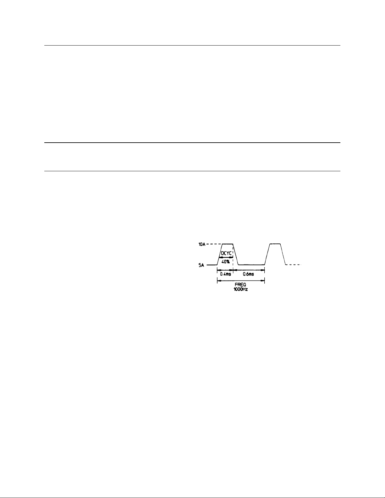
TRANsient:MODE CONTinuous
CURRent 5
CURRent:TLEVel 10
TRANsient:FREQuency 1000
TRANsient:DCYCle 40
TRANsient ON
Generates a repetitive pulse stream that toggles between two load levels.
Generates an load change that returns to its original state after some time period.
Generates a repetitive pulse stream that toggles between two load levels. Similar to
Continuous mode except that the transient points are controlled by explicit triggers
instead of an internal transient generator.
the parameters associated with transient operation. At *RST all transient functions are set
to OFF.
This example assumes that the CC mode is active and the slew rate is at the default setting (maximum
rate). The load module starts conduction at the main level (in this case 5 amps). When transient
operation is turned on (no trigger is required in continuous mode), the module input current will slew to
and remain at 10 amps for 40% of the period (400 µs). The input current will then slew to and remain at 5
amps for the remaining 60% (600 µs) of that cycle.
Pulse Transients
Pulsed transient operation generates a load change that returns to its original state after some time
period. It is similar to continuous operation with the following exceptions:
a. To get a pulse, an explicit trigger is required. To specify the trigger source, use
TRIGger:SOURce. See "Triggering Transients".
b. One pulse results from each trigger. Therefore, frequency cannot be programmed.
Use the following commands to program pulsed transients:
25
Page 24
3 - Programming Examples
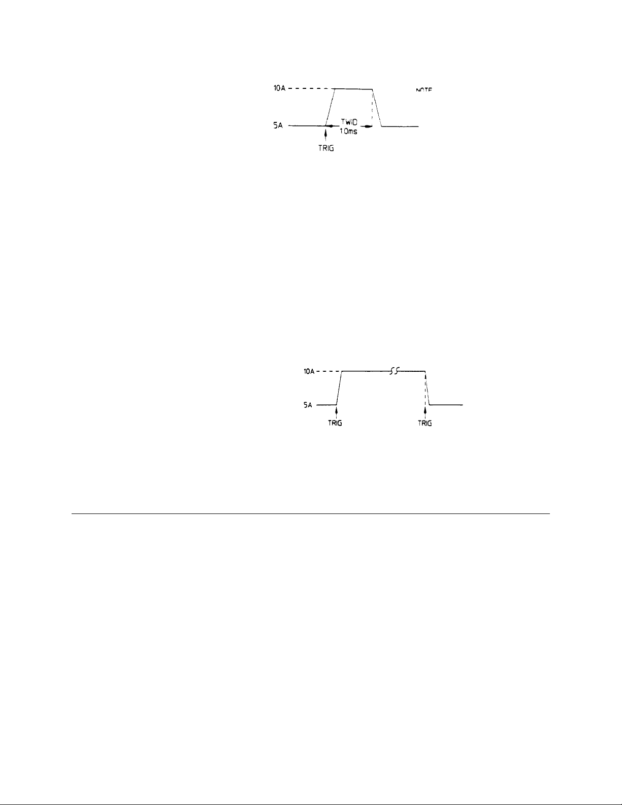
TRIGger:SOURce EXTernal
TRANsient:MODE PULSe
CURRent 5
CURRent:TLEVel 10
TRANsient:TWIDth .01
TRANsient ON
This example assumes that the CC mode is active, the slew rate is at the factory default setting
(maximum rate), and a trigger signal is connected to the mainframe's external trigger input. The load
module starts conduction at the main current level setting (5 amps). When the transient mode is turned
on and an external trigger signal is received, the input level starts increasing at a rate determined by the
slew rate. When the value specified by the transient level setting (10 amps) is reached, it stays there for
the remainder of the time determined by the pulse width setting (10 milliseconds). After this time has
elapsed, the input level decreases to the main level again at the rate specified by the slew setting and
remains there until another trigger is received. Any triggers that occur during the time the transient level is
in effect will re-trigger the pulse, extending the pulse by another pulse-width value.
Toggled Transients
Toggled transient operation causes the module input to alternate between two pre-defined levels as in
continuous operation except that the transient transitions are controlled by explicit triggers instead of the
internal transient generator. See "Triggering Transients". Use the following commands to program toggled
transients:
TRIGger:SOURce EXTernal
TRANsient:MODE TOGGle
CURRent 5
CURRent:TLEVel 10
TRANsient ON
This example assumes that the CC mode is active, the slew rate is at the factory default setting
(maximum rate), and a trigger signal is connected to the mainframe's external trigger input. Toggled
transient operation is similar to that described for continuous and pulse operation, except that each time a
trigger is received the input alternates between the main and transient input current levels.
Programming Lists
List mode lets you generate complex sequences of input changes with rapid, precise timing, which may be
synchronized with internal or external signals. This is useful when running test sequences with a minimum
amount of programming overhead.
You can program up to 50 settings (or steps) in the list, the time interval (dwell) that each setting is
maintained, the number of times that the list will be executed, and how the settings change in response to
triggers. All list data is can be stored in nonvolatile memory when saved in locations 0, 7, 8, or 9 using the
*SAV command. This means that the programmed data for any list will be retained when the electronic
load is turned off. Use the *RCL command to recall the saved state. *RST clears the presently active list
but will not clear the lists saved in locations 0, 7, 8, or 9.
List steps can be either individually triggered, or paced by a separate list of dwell times that define the
duration of each step. Therefore, each of the up to 50 steps has an associated dwell time, which specifies
the time (in seconds) that the input remains at that step before moving on to the next step. The following
procedure shows how to generate a simple 9-step list of current and voltage changes.
26
Page 25

Programming Examples - 3
Step 1
Step 2
Set the mode of each function that will participate in the sequence to LIST. For example:
CURRent:MODE LIST
Program the list of input values for each function. The list commands take a comma-separated
list of arguments. The order in which the arguments are given determines the sequence in
which the values will be input. For example, to vary the input current of the electronic load to
simulate a 25%, 50%, and 100% load, a list may include the following values:
LIST:CURRent[:LEVel] 15, 30, 60, 15, 30, 60, 15, 30, 60
You must specify a list for all current functions, whether or not the functions will be used. For
example, to synchronize the previous current list with another list that varies the slew rate from
0.01A/µs, to 0.1A/µs, to 1A/µs (programmed in A/s), the lists may include the following values:
LIST:CURRent[:LEVel] 15, 30, 60, 15, 30, 60, 15, 30, 60
LIST:CURRent:SLEW 1E+5, 1E+5, 1E+5, 1E+6, 1E+6, 1E+6, 1E+7, 1E+7, 1E+7
LIST:CURRent:RANGe 60
LIST:CURRent:TLEVel 0
All lists must have the same number of data values or points, or an error will occur when the list
system that starts the sequence is initiated. The exception is when a list has only one item or
point. In this case the single-item list is treated as if it had the same number of points as the
other lists, with all values being equal to the one item. For example:
LIST:CURRent 15, 30, 45, 60;SLEW 1E+6
is the same as:
LIST:CURRent 15, 30, 45, 60
LIST:CURRent:SLEW 1E+6, 1E+6, 1E+6, 1E+6
Step 3
Step 4
Step 5
Determine the time interval that the input remains at each level or point in the list before it
advances to the next point. The time is specified in seconds. For example, to specify five dwell
intervals, use:
LIST:DWELl 1, 1.5, 2, 2.5, 3
The number of dwell points must equal the number of input points. If a dwell list has only one
value, that value will be applied to all points in the input list.
Determine the number of times the list is repeated before it completes. For example, to repeat a
list 10 times use:
LIST:COUNt 10
Entering INFinity makes the list repeat indefinitely. At *RST, the count is set to 1.
Determines how the list sequencing responds to triggers. For a closely controlled sequence of
input levels, you can use a dwell-paced list. To cause the list to be paced by dwell time use:
LIST:STEP AUTO
As each dwell time elapses, the next point is immediately input. This is the *RST setting.
If you need the input to closely follow asynchronous events, then a trigger-paced list is more
appropriate. In a trigger-paced list, the list advances one point for each trigger received. To
enable trigger-paced lists use:
LIST:STEP ONCE
The dwell time of each point determines the minimum time that the input remains at that point.
If a trigger is received before the previous dwell time completes, the trigger is ignored.
Therefore, to ensure that no triggers are lost, program the dwell time to "MIN".
Step 6
Use the list trigger system to trigger the list. See "Triggering Transients and Lists".
27
Page 26

3 - Programming Examples
Programming Lists for Multiple Channels
You can program separate lists for individual channels on a load mainframe. Once lists have been
programmed for each channel, they can all be triggered at the same time using the list trigger system.
NOTE: All lists must have the same number of data values or points, or an error will occur when
the list system that starts the sequence is initiated.
Step 1
Step 2
Step 3
Step 4
Select the channel for which you want to program the list. All subsequent list commands will be
sent to this channel until another channel is selected.
CHANnel 1
Program the list of values for each function for that channel. The list commands take a comma-
separated list of arguments. For example:
LIST:CURRent 15, 30, 60, 15, 30, 60, 15, 30, 60
LIST:CURRent:SLEW 1E+5, 1E+5, 1E+5, 1E+6, 1E+6, 1E+6, 1E+7, 1E+7, 1E+7
.
.
.
Add other list functions.
Select the next channel for which you want to program a list. All subsequent list commands will
now be sent to this channel.
CHANnel 2
Program the list of values for each function for that channel. You can program different
functions for each channel, however all functions must have the same number of steps
LIST:VOLTage 30, 60, 30, 30, 60, 30, 30, 60, 30
LIST:VOLTage:SLEW 1E+5, 1E+5, 1E+5, 1E+6, 1E+6, 1E+6, 1E+7, 1E+7, 1E+7
.
.
.
Add other list functions. You do not have to program the same number of functions for each
channel.
Step 5
Step 6
28
Repeat steps 3 and 4 for any other channel that you wish to program.
Use the list trigger system to trigger the list. This is described under "Triggering Transients and
Lists".
Page 27
Programming Examples - 3
Triggering Transients and Lists
Continuous, pulse, and toggled transient modes respond to triggers as soon as the trigger is received.
This is not the case for lists. Lists have an independent trigger system that is similar to the measurement
trigger system. This section describes the list trigger system. The measurement trigger system is
described under "Triggering Measurements".
SCPI Triggering Nomenclature
In SCPI terms, trigger systems are called sequences. When more than one trigger system exists, they are
differentiated by naming them SEQuence1 and SEQuence2. SEQuence1 is the list trigger system and
SEQuence2 is the measurement trigger system. The electronic load uses aliases with more descriptive
names for these sequences. These aliases can be used instead of the sequence forms.
Sequence Form Alias
SEQuence1 LIST
SEQuence2 ACQuire
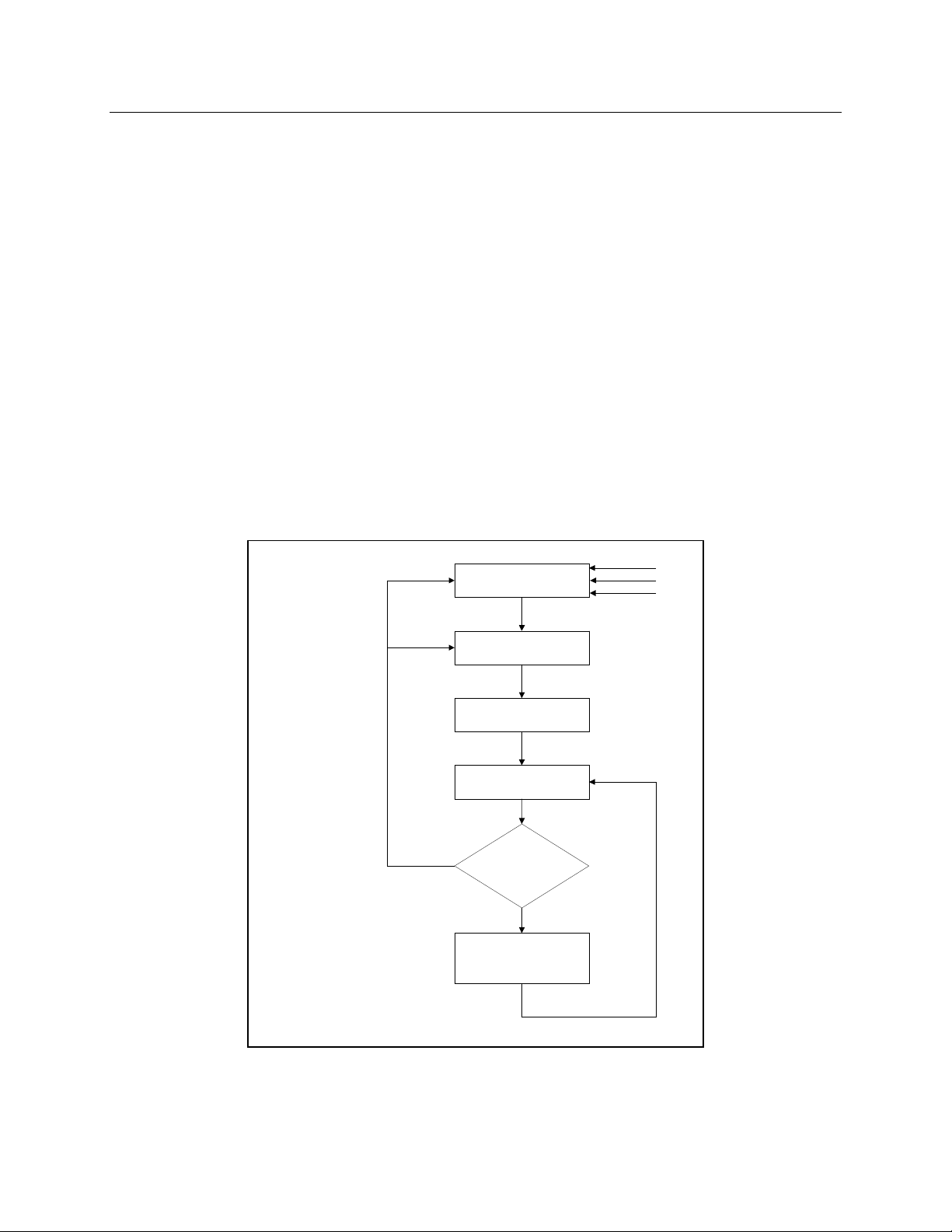
List Trigger Model
Figure 3-3 is a model of the list trigger system. The rectangles represent states. The arrows show the
transitions between states. These are labeled with the input or event that causes the transition to occur.
INITiate:CONTinuous OFF
INITiate:CONTinuous ON
or
List not complete and
LIST:STEP ONCE
INITIATED STATE
DELAYING STATE
LIST STEP CHANGE
NO
WAIT FOR DWELL
TO COMPLETE
IDLE STATE
LIST:STEP
AUTO?
YES
ABORt
*RST
*RCL
INITiate[:IMMediate]
TRIGGER RECEIVED
DELAY COMPLETED
Figure 3-3. Model of List Triggers
29
Page 28

3 - Programming Examples
Initiating List Triggers
When the electronic load is turned on, the list trigger system is in the idle state. In this state, the list
system ignores all triggers. Sending the following commands at any time returns the list system to the Idle
state:
ABORt
*RST
*RCL
The INITiate commands move the list system from the Idle state to the Initiated state. This enables the
list system to receive triggers. INITiate commands are not channel-specific, they affect all installed load
modules. To initiate the list system for a single triggered action, use:
INITiate:SEQuence1 or
INITiate:NAME LIST
NOTE: Whenever a list is initiated or triggered, the φ1 annunciator is lit on the front panel.
After a trigger is received and the action completes, the list system will return to the Idle state. Thus it will
be necessary to initiate the list system each time a triggered action is desired.
To keep the list system initiated for multiple actions without having to send an Initiate command for each
trigger, use:
INITiate:CONTinuous:SEQuence1 ON or
INITiate:CONTinuous:NAME LIST, ON
Specifying a Trigger Delay
A time delay can be programmed betweent he receipt of the trigger system and the start of the triggered
action. This delay applies to both list and measurement triggers. At *RST the trigger delay is set to 0,
which mens there is no trigger delay. To program a trigger delay use:
TRIGger:DELay <n>
Generating Transient and List Triggers
Use one of the following triggering methods to generate transients and lists:
TRIGger:SOURce BUS | EXTernal | HOLD | LINE | TIMer
After you have specified the appropriate trigger source, you can generate triggers as follows:
Single triggers over
the bus
Continuous triggers
synchronized with the
ac line frequency
Continuous triggers
synchronized with the
internal timer
Send one of the following commands over the GPIB:
TRIGger:IMMediate
*TRG
a group execute trigger
Send the following command over the GPIB:
TRIGger:SOURce LINE
Send the following commands over the GPIB:
TRIGger:TIMer <time>
TRIGger:SOURce TIMer
External trigger
30
Apply a low to high signal to the external trigger input at the back of the
mainframe.
Page 29

Programming Examples - 3
Making Measurements
The electronic load has the ability to make several types of voltage or current measurements. The
measurement capabilities of the electronic load are particularly useful with applications that draw current
in pulses.
All measurements are performed by digitizing the instantaneous input voltage or current for a defined
number of samples and sample interval, storing the results in a buffer, and then calculating the measured
result. Many parameters of the measurement are programmable. These include the number of samples,
the time interval between samples, and the method of triggering. Note that there is a tradeoff between
these parameters and the speed, accuracy, and stability of the measurement in the presence of noise.
There are two ways to make measurements:
♦ Use the MEASure commands to immediately start acquiring new voltage or current data, and
return measurement calculations from this data as soon as the buffer is full. This is the easiest
way to make measurements, since it requires no explicit trigger programming.
♦ Use an acquisition trigger to acquire the data. Then use the FETCh commands to return
calculations from the data that was retrieved by the acquisition trigger. This method gives you the
flexibility to synchronize the data acquisition with a trigger. FETCh commands do not trigger the
acquisition of new measurement data, but they can be used to return many different calculations
from the data that was retrieved by the acquisition trigger.
Making triggered measurements with the acquisition trigger system is discussed under "Triggering
Measurements".
NOTE: For each MEASure form of the query, there is a corresponding query that begins with the
header FETCh. FETCh queries perform the same calculation as their MEASure
counterparts, but do not cause new data to be acquired. Data acquired by an explicit
trigger or a previously programmed MEASure command are used.
Voltage and Current Measurements
The SCPI language provides a number of MEASure and FETCh queries, which return various
measurement parameters of voltage and current waveforms.
DC Measurements
To measure the dc input voltage or current, use:
MEASure:VOLTage? or
MEASure:CURRent?
DC voltage and current is measured by acquiring a number of readings at the selected time interval,
optionally applying a Hanning window function to the readings, and averaging the readings. Windowing is
a signal conditioning process that reduces the error in dc measurements made in the presence of periodic
signals such as line ripple. At power-on and after a *RST command, the following parameters are set:
SENSe:SWEep:TINTerval 10E-6
SENSe:SWEep:POINts 1000
This results in a data acquisition time of 10 milliseconds. Adding a command processing overhead of
about 20 milliseconds results in a total measurement time of about 30 milliseconds per measurement
sample.
31
Page 30

3 - Programming Examples
Ripple rejection is a function of the number of cycles of the ripple frequency contained in the acquisition
window. More cycles in the acquisition window results in better ripple rejection. If you increase the time
interval for each measurement to 45 microseconds for example, this results in 5.53 cycles in the
acquisition window at 60 Hz, for a ripple rejection of about 70 dB.
Note that the processing overhead time will vary, depending on the number of measurement samples. If
you reduce the number of sample points, you will also reduce the command processing overhead. If you
increase the number of sample point (up to a maximum of 4096) you increase the command processing
overhead.
RMS Measurements
To read the rms content of a voltage or current waveform, use:
MEASure:VOLTage:ACDC? or
MEASure:CURRent:ACDC?
This returns the total rms measurement, including the dc portion.
Minimum and Maximum Measurements
To measure the maximum or minimum voltage or current of a pulse or ac waveform, use:
MEASure:VOLTage:MAXimum?
MEASure:VOLTage:MINimum?
MEASure:CURRent:MAXimum?
MEASure:CURRent:MINimum?
Measurement Ranges
The electronic load has two current and two voltage measurement ranges. The commands that control the
measurement ranges are:
SENSe:CURRent:RANGe MIN | MAX
SENSe:VOLTage:RANGe MIN | MAX
When the range is set to MAX, the maximum current or voltage that can be measured is a function of the
current and voltage rating of the load module that is being programmed (see Table 4-1).
Returning Measurement Data From the Data Buffer
The MEASure and FETCh queries can also return all data values of the instantaneous voltage or current
buffer. The commands are:
FETCh:ARRay:CURRent?
FETCh:ARRay:VOLTage?
This is a useful feature if, for example, you have entered multiple measurements into the buffer as a result
of measuring the response to a triggered list. Data is returned from the buffer in the same order in which it
was entered into the buffer. Refer to "Synchronizing Transients and Measurements" for more information.
32
Page 31

Programming Examples - 3
Triggering Measurements
You can use the data acquisition trigger system to synchronize the timing of the voltage and current data
acquisition with a trigger source. Then use the FETCh commands to return different calculations from the
data acquired by the measurement trigger.
SCPI Triggering Nomenclature
In SCPI terms, trigger systems are called sequences. When more than one trigger system exists, they are
differentiated by naming them SEQuence1 and SEQuence2. SEQuence1 is the list trigger system and
SEQuence2 is the measurement trigger system. The electronic load uses aliases with more descriptive
names for these sequences. These aliases can be used instead of the sequence forms.
Sequence Form Alias
SEQuence2 ACQuire
Measurement Trigger Model
Figure 3-1 is a model of the measurement trigger system. The rectangular boxes represent states. The
arrows show the transitions between states. These are labeled with the input or event that causes the
transition to occur.
IDLE STATE
INITIATED STATE
DELAYING STATE
SENSe:SWEep:POINts
ACQUIRED
NO
TRIGger:COUNt
COMPLETE?
YES
ABORt
*RST
*RCL
INITiate[:IMMediate]
TRIGGER RECEIVED
DELAY COMPLETED
Figure 3-1. Model of Measurement Triggers
33
Page 32

3 - Programming Examples
Initiating the Measurement Trigger System
When the electronic load is turned on, the trigger system is in the idle state. In this state, the trigger
system ignores all triggers. Sending the following commands at any time returns the trigger system to the
Idle state:
ABORt
*RST
*RCL
The INITiate commands move the trigger system from the Idle state to the Initiated state. This enables the
electronic load to receive triggers. INITiate commands are not channel-specific, they affect all installed
load modules. To initiate a measurement trigger, use:
INITiate:SEQuence2 or
INITiate:NAME ACQuire
After a trigger is received and the data acquisition completes, the trigger system will return to the Idle state
unless multiple measurements are programmed using the TRIGger:SEQuence2:COUNt command. Thus
it will be necessary to initiate the system each time a triggered acquisition is desired.
NOTE: You cannot initiate measurement triggers continuously. Otherwise, the measurement data
in the data buffer would continuously be overwritten.
Generating Measurement Triggers
Use one of the following triggering methods to generate measurements:
TRIGger:SOURce BUS | EXTernal | HOLD | LINE | TIMer
After you have specified the appropriate source, you can generate measurement triggers as follows:
Single triggers over
the bus
Continuous triggers
synchronized with the
ac line frequency
Continuous triggers
synchronized with the
internal timer
External trigger
When the acquisition finishes, any of the FETCh queries can be used to return the results. Once the
measurement trigger is initiated, if a FETCh query is sent before the data acquisition is triggered or before
it is finished, the response data will be delayed until the trigger occurs and the acquisition completes. This
may tie up the controller if the trigger condition does not occur immediately.
Send one of the following commands over the GPIB:
TRIGger:IMMediate (this overrides TRIG:SOUR HOLD)
*TRG
a group execute trigger
Send the following command over the GPIB:
TRIGger:SOURce LINE
Send the following commands over the GPIB:
TRIGger:TIMer <time>
TRIGger:SOURce TIMer
Apply a low to high signal to the external trigger input at the back of the
mainframe.
One way to wait for results without tying up the controller is to use the SCPI command completion
commands. For example, you can send the *OPC command after INITialize, then occasionally poll the
OPC status bit in the standard event status register for status completion while doing other tasks. You can
also set up an SRQ condition on the OPC status bit going true, and do other tasks until an SRQ interrupt
occurs.
34
Page 33

Programming Examples - 3
Controlling Measurement Samples
Varying the Sampling Rate
You can vary both the number of data points in a measurement sample, as well as the time between
samples. You can also specify a delay from the trigger to the start of the measurement. This is illustrated
in the following figure.
SENS:SWE:POIN <value>
SENS:SWE:TINT <value>
SENS:SWE:OFFS <value>
Trigger1 Trigger2 Trigger4Trigger3
TRIG:SEQ2:COUN <value>
Figure 3-2. Sense Commands Used to Vary the Sampling Rate
At power-on, the input voltage and current sampling rate is 10 microseconds. This means that, not
accounting for the command processing overhead, it takes about 41 milliseconds to fill up 4096 data
points in the data buffer. You can vary this data sampling rate with:
SENSe:SWEep:TINTerval <sample_period>
SENSe:SWEep:POINts <points>
For example, to set the time interval to 50 microseconds per sample with 500 samples, use:
SENSe:SWEep:TINTerval 50E-6;POINts 500.
Measurement Delay
You can delay the start of a measurement in relation to the trigger. This is useful if you do not want to start
taking measurements at the beginning of an input transient or list step during the time that the input
voltage or current is still slewing or settling into its programmed value. To offset the measurement from
the beginning of the input transient or list step, use:
SENSe:SWEep:OFFSet 10E-3
In this example, the measurement occurs 10 milliseconds after the start of the trigger. The offset can be
set to a negative value, but this number cannot exceed the TRIGger:DELay value.
Multiple Measurements
The electronic load also has the ability to set up several acquisition triggers in succession and
concatenate the results from each acquisition in the measurement buffer. This is useful for making
measurements from lists. To set up the trigger system for a number of sequential acquisitions use:
TRIGger:SEQuence2:COUNt <number>
35
Page 34

3 - Programming Examples
With this setup, the instrument performs each acquisition sequentially, storing the digitized readings in the
internal measurement buffer. A trigger signal is required to make each measurement. It is only necessary
to initialize the measurement once at the start; after each completed acquisition the instrument will wait for
the next valid trigger condition to start another. The results returned by MEASure or FETCh will be the
average of the total data acquired.
If you do not want the instrument to average the acquisition data, use the FETCh:ARRay commands to
return the raw data from the voltage or current measurement buffer.
NOTE: The total number of data points cannot exceed 4096. This means that the trigger count
multiplied by the number of points cannot exceed 4096; otherwise an error will occur.
Synchronizing Transients and Measurements
The transient and measurement systems are independent of each other. However, it possible to
synchronize the two systems through the use of triggers. This is because when both transient and
measurement systems have been initialized, the same trigger signal will affect both systems. For
example, you may have an application where you need to measure the effects of a list step.
Measuring Triggered Transients or Lists
Measuring triggered transients or lists is generally a straightforward process because you are using the
same trigger to generate the output transient and simultaneously take the measurement. The following
example illustrates how to make measurements from a simple 3-step trigger paced list. Each list step has
a duration of two seconds. Each step-measurement consists of three data points with an offset of 100
milliseconds.
Step 1
Step 2
Step 3
Step 4
Set the mode of each function that will participate in the sequence to LIST. For example:
CURRent:MODE LIST
Program the list of input values for each function.
LIST:CURRent 15, 30, 60
LIST:CURRent:SLEW 1E+6, 1E+6, 1E+6
LIST:CURRent:RANGe 60
LIST:CURRent:TLEVel 0
Specify the number of triggered measurements that will be taken.
TRIGger:SEQuence2:COUNt 3
The number of measurements should match the number of steps in the list.
Specify the time interval and the number of points in each triggered measurement.
SENSe:SWEep:TINTerval 100E-3
SENSe:SWEep:POINts 3
In this example, three measurements or data points are taken at each list step, separated by
100ms intervals. Make sure that all of the measurement samples complete within the step time
interval. If another trigger occurs while a measurement is in progress, the measurement
system will ignore the trigger. Also note that the number of data points specified in this step
multiplied by the measurement count specified in step 3 cannot exceed 4096.
Step 5
36
Specify a delay time from the start of the trigger until the measurement is taken.
SENSe:SWEep:OFFset 100E-6
This specifies the offset in seconds, in this case, 100 microseconds
Page 35

Programming Examples - 3
Step 6
Step 7
Step 8
NOTE: Each load module retains its measurement data. If multiple lists have been executed, you
Initiate both the transient (list) and the measurement trigger systems.
INITiate:SEQuence1
INITiate:SEQuence2
Specify the trigger source and the timing that will control the list steps and the measurements.
TRIGger:TIMer 2
TRIGger:SOURce TIMer
In this example the trigger source is the internal trigger. Because the internal timer starts
running as soon as the TRIGger:SOURce:TIMer command is executed, the trigger that starts
the list and measurement will not occur until the end of the two-second timer window within
which the trigger is received. After the initial trigger occurs, the list will remain at each step for
two seconds before the next trigger occurs.
Return the current measurements from the data array. In this case, a total of nine
measurements were taken, three at each list step. To return the measurement data you must
first dimension an array, then fetch the data.
Dimension an array here
FETch:CURRent:ARRay ARRAY1
must select each channel in turn, and fetch the measurement data from that channel.
Measuring Dwell-Paced Lists
The main difference between a trigger-paced list and a dwell-paced list is that no triggers occur between
steps in a dwell-paced list. Only one measurement will be taken during the time the list is executed.
Therefore, to capture measurement data for the entire time the list is executed, the total measurement
time of a dwell paced list (time interval X number of points) must equal the total dwell time of the list.
Step 1
Step 2
Step 3
Step 4
Step 5
Program the list as previously described under "Measuring Triggered Transients or Lists."
Specify a dwell time for each list step. For example:
LIST:DWELl 1, 1.5, 2, 2.5, 3
Add up the total number of dwell times to determine the time of the entire list. For the previous
example, the total dwell time adds up to 10 seconds. This is the time it takes to execute the
list.
Specify the time interval and the number of points for the measurement.
SENSe:SWEep:TINTerval 100E-3
SENSe:SWEep:POINts 100
In this example, the measurement interval is set to take 100 measurement points at 100ms
intervals. The total time of the measurement therefore equals the total dwell time of the list.
Return the measurements from the data array.
Dimension an array here
FETch:CURRent:ARRay ARRAY1
When you read back the measurement from the array, you must determine at what point
during the list that the measurement occurred. One way to do this is to multiply the
measurement number by the measurement interval. For example, multiply measurement #5 by
100ms, and you get 500ms, which is the time that the measurement was made.
37
Page 36

3 - Programming Examples
Programming the Status Registers
You can use status register programming to determine the operating condition of the electronic load at any
time. For example, you may program the electronic load to generate an interrupt (assert SRQ) when an
event such as a current protection occurs. When the interrupt occurs, your program can then act on the
event in the appropriate fashion.
Table 3-1 defines the status bits. Figure 3-4 shows the status register structure of the electronic load. The
Standard Event, Status Byte, and Service Request Enable registers and the Output Queue perform
standard GPIB functions as defined in the IEEE 488.2 Standard Digital Interface for Programmable
Instrumentation. The Operation Status and Questionable Status registers implement functions that are
specific to the electronic load.
Table 3-1. Bit Configurations of Status Registers
Bit Signal Meaning
Operation Status Group
0
5
0
1
3
4
8
9
10
11
12
13
CAL
WTG
VF
OC
OP
OT
EPU
RRV
UNR
LRV
OV
PS
Calibrating. The electronic load is computing new calibration constants
Waiting. The electronic load is waiting for a trigger
Channel Status Group
Voltage Fault. Either an overvoltage or a reverse voltage has occurred. This bit reflects
the active state of the FLT pin on the back of the unit. The bit remains set until the
condition is removed and INP:PROT:CLE is programmed.
Overcurrent. An overcurrent condition has occurred. This occurs if the current exceeds
102% of the rated current or if it exceeds the user-programmed current protection level.
Removing the overcurrent condition clears the bit. If the condition persists beyond the
user programmable delay time, bit 13 is also set and the input is turned off. Both bits
remain set until the condition is removed and INP:PROT:CLE is programmed.
Overpower. An overpower condition has occurred. This occurs if the unit exceeds the
rated power of the input. Removing the overpower condition clears the bit. If the condition
persists for more than 3 seconds, bit 13 is also set and the input is turned off. Both bits
remain set until the condition is removed and INP:PROT:CLE is programmed.
Overtemperature. An overtemperature condition has occurred. Both this bit and bit 13 are
set and the input is turned off. Both bits remain set until the unit is cooled down and
INP:PROT:CLE is programmed.
Extended Power Unavailable. When EPU status is true, an overpower condition that
persists for more than 3 seconds will cause the input to be shut off and bit 13 to be set.
When EPU satus is false, an overpower condition will be reported in bit 3, but this will not
cause the input to be turned off. The state of the EPU bit is dependent on the internal
temperature of the load.
Remote Reverse Voltage. A reverse voltage condition has occurred on the sense
terminals. Both this bit and bit 0 are set. Removing the reverse voltage clears this bit but
does not clear bit 0. Bit 0 remains set until INP:PROT:CLE is programmed.
Unregulated. The input is unregulated. When the input is regulated the bit is cleared.
Local Reverse Voltage. A reverse voltage condition has occurred on the input terminals.
Both this bit and bit 0 are set. Removing the reverse voltage clears this bit but does not
clear bit 0. Bit 0 remains set until INP:PROT:CLE is programmed.
Overvoltage. An overvoltage condition has occurred. Both this bit and bit 0 are set and the
FETs are turned on as hard as possible to lower the voltage. Both bits remain set until the
condition is removed and INP:PROT:CLE is programmed.
Protection Shutdown. The protection shutdown circuit has tripped because of an
overcurrent, overpower, or overtemperature condition. The bit remains set until
INP:PROT:CLE is programmed.
38
Page 37

Programming Examples - 3
Table 3-1. Bit Configurations of Status Registers (continued)
Questionable Status Group
Same as Channel Status Group
Standard Event Status Group
0
2
3
4
5
7
OPC
QYE
DDE
EXE
CME
PON
Operation Complete. The load has completed all pending operations. *OPC must be
programmed for this bit to be set when pending operations are complete.
Query Error. The output queue was read with no data present or the data was lost. Errors
in the range of −499 through −400 can set this bit.
Device-Dependent Error. Memory was lost or self test failed. Errors in the range of −399
through −300 can set this bit.
Execution Error. A command parameter was outside its legal range, inconsistent with the
load's operation, or prevented from executing because of an operating condition. Errors in
the range of −299 through −200 can set this bit.
Command Error. A syntax or semantic error has occurred or the load received a <get>
within a program message. Errors in the range of −199 through −100 can set this bit.
Power-On. The unit has been turned off and then on since this bit was last read.
Status Byte and Service Request Enable Registers
2
3
4
5
6
7
CSUM
QUES
MAV
ESB
MSS
RQS
OPER
Channel Summary. Indicates if an enabled channel event has occurred.
Questionable Status Summary. Indicates if an enabled questionable event has occurred.
Message Available Summary. Indicates if the Output Queue contains data.
Event Status Summary. Indicates if an enabled standard event has occurred.
Master Status Summary. For an *STB? query, MSS is returned without being cleared.
Request Service. During a serial poll, RQS is returned and cleared.
Operation Status Summary. Indicates if an operation event has occurred.
39
Page 38

3 - Programming Examples
CONDITION
0
1
1
4
2
3
8
4
16
8
256
9
512
1024
2048
4096
8192
CHANNEL STATUS
EVENT ENABLE
1
2
8
16
256
512
1024
2048
4096
8192
1024
2048
4096
8192
1
2
CHANNEL SUMMARY
EVENT ENABLE
8
16
256
512
LOGICAL
OR
SAME
AS
CHAN 1
CHAN 1
CHAN 2
CHAN 3
CHAN 4
CHAN 5
CHAN 6
N.U.
0
1
2
2
4
3
8
4
16
5
32
6
64
2
4
8
16
32
64
LOGICAL
OR
(IDENTICAL REGISTERS FOR EACH CHANNEL)
VF
OC
N.U.
OP
OT
5-7
N.U.
RRV
EPU
10
UNR
11
LRV
12
OV
13
PS
5-9
N.U.
QUESTIONABLE STATUS
SAME
AS
CHAN 1
CHAN 1
CHAN 2
CHAN 3
CHAN 4
CHAN 5
CHAN 6
VF
VF
VF
LOGICAL
OR
VF
VF
VF
N.U.
OP
OT
N.U.
UNR
LRV
OV
PS
N.U.
VF
OC
RRV
EPU
CONDITION
0
1
2
3
4
16
5-7
8
256
9
512
10
1024
11
2048
12
4096
13
8192
5-9
1
4
8
EVENT ENABLE
1024
2048
4096
8192
1
2
8
16
256
512
256
1024
2048
4096
8192
1
2
8
16
512
LOGICAL
OR
OPC
N.U.
QYE
DDE
EXE
CME
N.U.
PON
CAL
N.U.
WTG
N.U.
0
1-4
5
6-15
STANDARD EVENT
STATUS
EVENT ENABLE
0
1
1
2
4
3
8
4
16
5
32
6
7
128
1
4
8
16
32
128
LOGICAL
OR
OPERATION STATUS
CONDITION
PTR/NTR EVENT ENABLE
11 1
32 32 32
Figure 3-4. Electronic Load Status Model
OUTPUT QUEUE
DATA
DATA
DATA
1
32
QUEUE
NOT
EMPTY
LOGICAL
OR
N.U.
CSUM
QUES
MAV
ESB
RQS
OPER
STATUS BYTE
0,1
2
4
3
8
4
16
5
32
6
7
128
RQS
SERVICE
REQUEST
GENERATION
SERVICE
REQUEST
ENABLE
4
8
16
32
128
LOGICAL
OR
40
Page 39

Programming Examples - 3
Power-On Conditions
Refer to the *RST command description in chapter 4 for the power-on conditions of the status registers.
Channel Status Group
The Channel Status registers record signals that indicate abnormal operation of a specific channel of the
electronic load. As shown below, the group consists of a Condition, Event, and Enable register. The
outputs of the Channel Status registers are logically-ORed into the Channel Summary Registers.
Register Command Description
Condition
Event
Enable
STAT:CHAN:COND?
STAT:CHAN:EVEN?
STAT:CHAN:ENAB <n>
A read-only register that holds real-time status of the channel
being monitored.
A read-only register that latches any condition. It is cleared
when read.
A read/write register that functions as a mask for enabling
specific bits in the Event register.
Channel Summary Group
The Channel Summary registers summarize the abnormal operation of all channels of the electronic load.
As shown below, the group consists of an Event and Enable register. The outputs of the Channel
Summary registers are logically-ORed into the Channel SUMmary bit (2) of the Status Byte register.
Register Command Description
Event
Enable
STAT:CSUM:EVEN?
STAT:CSUM:ENAB <n>
A read-only register that latches any condition from all
channels. It is cleared when read.
A read/write register that functions as a mask for enabling
specific bits in the Enable register.
Questionable Status Group
The Questionable Status registers record signals that indicate abnormal operation of the electronic load
from all of the channels. The group consists of the same type of registers as the Channel Status group.
The outputs of the Questionable Status group are logically-ORed into the QUEStionable summary bit (3)
of the Status Byte register.
Register Command Description
Condition
Event
Enable
STAT:QUES:COND?
STAT:QUES:EVEN?
STAT:QUES:ENAB <n>
A read-only register that holds real-time logically ORed status
of all channels of the mainframe.
A read-only register that latches any condition. It is cleared
when read.
A read/write register that functions as a mask for enabling
specific bits in the Enable register.
Standard Event Status Group
This group consists of an Event register and an Enable register that are programmed by Common
commands. The Standard Event event register latches events relating to instrument communication status
(see figure 3-4). It is a read-only register that is cleared when read. The Standard Event enable register
functions similarly to the enable registers of the Operation and Questionable status groups.
41
Page 40

3 - Programming Examples
Command Action
*ESE
*PSC ON
*ESR?
The PON (Power On) Bit
The PON bit in the Standard Event event register is set whenever the electronic load is turned on. The
most common use for PON is to generate an SRQ at power-on following an unexpected loss of power. To
do this, bit 7 of the Standard Event enable register must be set so that a power-on event registers in the
ESB (Standard Event Summary Bit), bit 5 of the Service Request Enable register must be set to permit an
SRQ to be generated, and *PSC OFF must be sent. The commands to accomplish these conditions are:
*PSC OFF *ESE 128 *SRE 32
programs specific bits in the Standard Event enable register.
clears the Standard Event enable register at power-on.
reads and clears the Standard Event event register.
Operation Status Group
The Operation Status registers record signals that occur during normal operation. As shown below, the
group consists of a Condition, PTR/NTR, Event, and Enable register. The outputs of the Operation Status
register group are logically-ORed into the OPER(ation) summary bit (7) of the Status Byte register.
Register Command Description
Condition
PTR Filter
NTR Filter
Event
Enable
STAT:OPER:COND?
STAT:OPER:PTR <n>
STAT:OPER:NTR <n>
STAT:OPER:EVEN?
STAT:OPER:ENAB <n>
A read-only register that holds real-time status of the circuits
being monitored.
A read/write positive transition filter that functions as described
in chapter 4 under STAT:OPER:NTR|PTR.
A read/write negative transition filter that functions as described
in chapter 4 under STAT:OPER:NTR|PTR.
A read-only register that latches any condition that is passed
through the PTR or NTR filters. It is cleared when read.
A read/write register that functions as a mask for enabling
specific bits from the Event register.
Status Byte Register
This register summarizes the information from all other status groups as defined in the IEEE 488.2
Standard Digital Interface for Programmable Instrumentation. The bit configuration is shown in Table 3-1.
Command Action
*STB? reads the data in the register but does not clear it (returns MSS in bit 6)
serial poll clears RQS inside the register and returns it in bit position 6 of the response.
The MSS Bit
This is a real-time (unlatched) summary of all Status Byte register bits that are enabled by the Service
Request Enable register. MSS is set whenever the electronic load has one or more reasons for requesting
service. *STB? reads the MSS in bit position 6 of the response but does not clear any of the bits in the
Status Byte register.
The RQS Bit
The RQS bit is a latched version of the MSS bit. Whenever the electronic load requests service, it sets the
SRQ interrupt line true and latches RQS into bit 6 of the Status Byte register. When the controller does a
serial poll, RQS is cleared inside the register and returned in bit position 6 of the response. The remaining
bits of the Status Byte register are not disturbed.
42
Page 41

Programming Examples - 3
The MAV Bit and Output Queue
The Output Queue is a first-in, first-out (FIFO) data register that stores electronic load-to-controller
messages until the controller reads them. Whenever the queue holds one or more bytes, it sets the MAV
bit (4) of the Status Byte register.
Determining the Cause of a Service Interrupt
You can determine the reason for an SRQ by the following actions:
Step 1 Determine which summary bits are active. Use:
*STB? or serial poll
Step 2 Read the corresponding Event register for each summary bit to determine which events
caused the summary bit to be set. Use:
STATus:QUEStionable:EVENt?
STATus:OPERation:EVENt?
ESR?
When an Event register is read, it is cleared. This also clears the corresponding summary
bit.
Step 3 Remove the specific condition that caused the event. If this is not possible, the event may
be disabled by programming the corresponding bit of the status group Enable register or
NTR|PTR filter if there is one. A faster way to prevent the interrupt is to disable the service
request by programming the appropriate bit of the Service Request Enable register
Servicing Standard Event Status and Questionable Status Events
This example assumes you want a service request generated whenever the electronic load experiences a
command execution error, or whenever the electronic load's overcurrent, overpower, or overtemperature
circuits have tripped. From figure 3-4, note the required path for a condition at bit 4 (EXE) of the Standard
Event Status register to set bit 6 (RQS) of the Status Byte register. Also note the required path for
Questionable Status conditions at bits 1, 3, and 4 to generate a service request (RQS) at the Status Byte
register. The required register programming is as follows:
Step 1 Program the Standard Event Status register to enable an event at bit 4. This allows the
event to be summed into the ESB bit of the Status Byte Register. Use:
*ESE 4
Step 2 Program the Questionable Status register to allow an event at bits 1, 3, or 4 to be
summed into the Questionable summary bit. Use:
STATus:QUEStionable:ENABle 26 (2 + 8 + 16 = 26)
Step 3 Program the Service Request Enable register to allow both the Standard Event Status
and the Questionable summary bits from the Status Byte register to generate RQS. Use:
*SRE 40 (8 + 32 = 40)
Step 4 When you service the request, read the event registers to determine which Operation
Status and Questionable Status Event register bits are set, and clear the registers for the
next event. Use:
STATus:OPERation:EVENt;QUEStionable:EVENt?
43
Page 42

3 - Programming Examples
Programming Examples
NOTE: Because of the wide variety of input ratings between load modules, not all of the values
used in the following programming examples will work with every module.
CC Mode Example
This example selects channel 1, sets the current level to 1.25 A and reads back the actual current value.
10 OUTPUT 705; "CHAN 1"
20 OUTPUT 705;"INPUT OFF"
30 OUTPUT 705;"FUNC CURR"
40 OUTPUT 705;"CURR:RANG MIN"
50 OUTPUT 705;"CURR 1.25"
60 OUTPUT 705;"INPUT ON"
70 OUTPUT 705;"MEAS:CURR?"
80 ENTER 705;A
90 DISP A
100 END
Line 10: Selects the channel 1 module.
Line 20: Turns off the input.
Line 30: Selects the CC mode.
Line 40: Selects the low current range.
Line 50: Sets the current level to 1.25 amps.
Line 60: Turns on the input.
Line 70: Measures the actual input current and stores it in a buffer inside the electronic load.
Line 80: Reads the input current value into variable A in the computer.
Line 90: Displays the measured current value on the computer's display.
CV Mode Example
This example selects channel 2, presets the voltage level to 10 volts, and selects the external trigger
source. When the external trigger signal is received, the channel 2 CV level will be set to 10 volts.
10 OUTPUT 705; "CHAN 2;:INPUT OFF"
20 OUTPUT 705;"FUNC VOLT"
30 OUTPUT 705;"VOLT 0"
40 OUTPUT 705;"VOLT:TRIG 10"
50 OUTPUT 705;"TRIG:SOUR EXT"
60 OUTPUT 705;"INPUT ON"
70 END
Line 10: Selects channel 2 and turns off the input.
Line 20: Selects the CV mode.
Line 30: Sets the initial voltage level to 0 volts.
Line 40: Sets the triggered voltage level to 10 volts.
Line 50: Selects the external input as the trigger source.
Line 60: Turns on the channel 2 input.
44
Page 43

Programming Examples - 3
CR Mode Example
This example selects channel 1, sets the current protection limit to 2 amps, programs the resistance level
to 100 ohms, and reads back the computed power.
10 OUTPUT 705;"CHAN 1;:INPUT OFF"
20 OUTPUT 705;"FUNC RES"
30 OUTPUT 705;"CURR:PROT:LEV 2;DEL 0.5"
40 OUTPUT 705;"CURR:PROT:STAT ON"
50 OUTPUT 705;"RES:RANG MAX"
60 OUTPUT 705;"RES 1000"
70 OUTPUT 705;”INPUT ON"
80 OUTPUT 705;”MEAS:POW?"
90 ENTER 705;A
100 DISP A
110 END
Line 10: Selects channel 1 and turns off the input.
Line 20: Selects the CR mode.
Line 30: Sets the current protection limit to 2 amps with a trip delay of 5 seconds.
Line 40: Enables the current protection feature.
Line 50: Selects the high resistance range.
Line 60: Sets the resistance level to 1000 ohms.
Line 70: Turns on the input.
Line 80: Reads the computed input power value and stores it in a buffer inside the electronic load.
Line 90: Reads the computed input power level into variable A in the computer.
Line 100: Displays the computed input power level on the computer's display.
Continuous Transient Operation Example
This example selects channel 2, sets the CC levels and programs the slew, frequency, and duty cycle
parameters for continuous transient operation.
10 OUTPUT 705;"CHAN 2;:INPUT OFF"
20 OUTPUT 705;"FUNC CURR"
30 OUTPUT 705;"CURR 1"
40 OUTPUT 705;"CURR:TLEV 2;SLEW MAX"
50 OUTPUT 705;"TRAN:MODE CONT;FREQ 5000;DCYC 40"
60 OUTPUT 705;"TRAN ON;:INPUT ON"
70 END
Line 10: Selects channel 2 and turns the input off
Line 20: Selects the CC mode.
Line 30: Sets the main current level to 1 ampere.
Line 40: Sets the transient current level to 2 amps and the slew rate to maximum.
Line 50: Selects continuous transient operation, sets the transient generator frequency to 5 kHz, and sets the duty
cycle to 40%.
Line 60: Turns on the transient generator and the input.
45
Page 44

3 - Programming Examples
Pulsed Transient Operation Example
This example selects channel 1, sets the CR levels, selects the bus as the trigger source, sets the fastest
slew rate, programs a pulse width of 1 millisecond, and turns on transient operation. When the *TRG
command is received, a 1 millisecond pulse is generated at the channel 1 input.
10 OUTPUT 705;"CHAN 1;:INPUT OFF"
20 OUTPUT 705;"FUNC RES"
30 OUTPUT 705;"RES:RANG MAX; LEV 1000"
40 OUTPUT 705;"RES:TLEV 2000"
50 OUTPUT 705;"TRIG:SOUR BUS"
60 OUTPUT 705;"RES:SLEW MAX"
70 OUTPUT 705;"TRAN:MODE PULS;TWID .001"
80 OUTPUT 705;"TRAN ON;:INPUT ON"
200 OUTPUT 705;"*TRG"
210 END
Line 10: Selects channel 1 and turns the input off.
Line 20: Selects the CR mode.
Line 30: Selects the high resistance range and sets the main resistance level to 100 ohms.
Line 40: Sets the transient resistance level to 50 ohms.
Line 50: Selects the HP-IB as the trigger source.
Line 60: Sets the CR slew rate to the maximum value.
Line 70: Selects pulsed transient operation and sets the pulse width to 1 millisecond.
Line 80: Turns on the transient generator and the input.
Other commands are executed
Line 200: The *TRG command generates a 1 millisecond pulse at the channel 1 input.
Synchronous Toggled Transient Operation Example
This example programs channels 1 and 2 to generate synchronous transient waveforms. The channels
can then be paralleled for increased current input. Each channel is set up to operate in the CC mode with
toggled transient operation turned on. The electronic load's internal trigger oscillator is set up to produce
trigger pulses at a frequency of 2 kHz in order to generate synchronous waveforms at the channel 1 and
channel 2 inputs.
10 OUTPUT 705;"CHAN 1;:INPUT OFF"
20 OUTPUT 705;"FUNC CURR"
30 OUTPUT 705;"CURR 25"
40 OUTPUT 705;"CURR:TLEV 50; SLEW MAX"
50 OUTPUT 705;"TRAN:MODE TOGG"
60 OUTPUT 705;"TRAN ON;:INPUT ON"
70 OUTPUT 705; "CHAN 2;:INPUT OFF"
80 OUTPUT 705;"FUNC CURR"
90 OUTPUT 705; "CURR 25"
100 OUTPUT 705; "CURR:TLEV 50; SLEW MAX"
110 OUTPUT 705;"TRAN:MODE TOGG"
120 OUTPUT 705;"TRAN ON;:INPUT ON"
130 OUTPUT 705;"TRIG:TIM .0005"
140 OUTPUT 705; "TRIG:SOUR TIM"
150 END
46
Page 45

Programming Examples - 3
Line 10: Selects channel 1 and turns the input off.
Line 20: Selects the CC mode.
Line 30: Sets the main current level to 25 A.
Line 40: Sets the transient current level to 50 A and the slew rate to maximum.
Line 50: Selects toggled transient operation.
Line 60: Enables transient operation and turns on the channel 1 input.
Line 70: Selects channel 2 and turns the input off.
Line 80: Selects the CC mode.
Line 90: Sets the main current level to 25 A.
Line 100: Sets the transient current level to 50 A and the slew to maximum.
Line 110: Selects toggled transient operation.
Line 120: Enables transient operation and turns on the channel 2 input.
Line 130: Sets the internal trigger oscillator frequency to 2 kHz (period of pulses = 0.0005).
line 140: Selects the electronic load's internal oscillator as the trigger source. The oscillator starts running as soon
as this line is executed.
Battery Testing Example
The principal measurement of a battery's performance is its rated capacity. The capacity of a fully charged
battery, at a fixed temperature, is defined as the product of the rated discharge current in amperes and the
discharge time in hours, to a specified minimum termination voltage in volts (see figure 3-5). A battery is
considered completely discharged when it reaches the specified minimum voltage called the "end of
discharge voltage" (EODV).
Figure 3-5. Typical Discharge Curve
In this example, the electronic load discharges three nickel-cadmium batteries to determine their
discharge rates at a fixed temperature (see Figure 3-6). The batteries are connected in series so that
when the EODV is reached, it is still above the minimum operating voltage of the electronic load. The
EODV for nickel-cadmium batteries is typically 1.0 volts.
47
Page 46

3 - Programming Examples
Figure 3-6. Batteries in Series
Battery Test Example Program
l0 ! Battery Test Example Program
20 !
30 Eodv=l.0 ! End of discharge voltage for single cell
40 Number_of_cells=3 ! Number of cells to be discharged in series
50 Discharge_at=.05 ! Constant current discharge rate in amperes
60 !
70 OUTPUT 705;
80 OUTPUT 705;"FUNCTION CURRENT" ! Sets CC mode
90 OUTPUT 705;"CURRENT:LEVEL";Discharge_at ! Sets the CC level
l00 OUTPUT 705;"INPUT ON" ! Enables the input
110 !
120 Start_time=TIMEDATE ! Records test start time
130 !
140 Start_test: ! Starts test routine that
150 OUTPUT 705;"MEASURE:VOLTAGE?" ! continuously measures and reads
160 ENTER 705;Sum_of_volts ! back the voltage and current
170 OUTPUT 705;"MEASURE:CURRENT?" ! until batteries are completely
180 ENTER 705;Actual_current ! discharged
190 !
200 PRINT "Total cell voltage: ";Sum_of_volts
210 PRINT "Actual current: ";Actual_current
220 PRINT "Elapsed time in seconds: ";TIMEDATE-Start_time
230 !
240 IF Sum_of_volts>(Number_of_cells*Eodv) THEN GOTO Start_test
250 ! Checks if the total voltage is less than the
260 ! sum of the minimum cell voltages of all cells
270 !
280 OUTPUT 705;"INPUT OFF" ! Disables the input
290 !
300 END
"CHAN 1;:INPUT OFF" ! Selects Chan 1; Disables input
48
Page 47

Programming Examples - 3
Power Supply Testing Example
A typical use for electronic loads when testing power supplies involves power supply burn-in. One of the
problems associated with burn-in is what to do if the power supply fails before the test is over. One
solution involves continuously monitoring the supply and removing the load if the supply fails during the
test (see figure 3-7).
In this example, the electronic load is used to burn-in a power supply at its rated output current. Because
the electronic load is operating in CC mode, if the power supply's output current drops below the rated
output current during the test, the UNR (unregulated) condition will be set on the electronic load. This can
be used to indicate that a failure has occurred on the power supply. If the unregulated condition persists
for a specified time, the inputs of the electronic load are turned off.
The purpose of this example is not to illustrate power supply testing, but to explain how to program and
use the status registers on the electronic load. The part of the program that runs the test simply monitors
the supply at the rated output current for one hour and stops the test. You can replace this portion of the
program with your own routine to test the power supply. Although SRQ (service request) is enabled to
interrupt only on the UNR bit in this example, you can modify the program to interrupt on other conditions.
Figure 3-7. Typical Burn-In Test
Power Supply Test Example Program
l0 ! Power Supply Test Example Program
20 !
30 Current=10 ! Load current in amperes
40 Burn_in_time=36000 ! One hour burn-in time
50 !
60 ON INTR 7 GOSUB Srq_service ! Set up interrupt linkage
70 ENABLE INTR 7;2 ! Enable interrupts for SRQs
80 !
90 OUTPUT 705;
l00 OUTPUT 705;"*SRE 4" ! Enable SRQ (SRQ enable for CSUM)
110 OUTPUT 705;"STAT:CSUM:ENAB 2" ! Enable Chan 1 (channel summary)
120 OUTPUT 705;"STAT:CHAN:ENAB l024" ! Enable UNR bit (channel status)
130 OUTPUT 705;"FUNCTION CURRENT" ! Sets CC mode
140 OUTPUT 705;"CURRENT:LEVEL";Current ! Sets the CC level
l50 OUTPUT 705;"INPUT ON" ! Enables the input
160 !
170 PRINT "Burn-in test started at ";TIME$(TIMEDATE)
180 !
190 FOR I=1 TO Burn_in_time ! Loop on wait You can write your
200 WAIT .1 ! own power supply test routine and
210 NEXT I ! insert it in this section
220 !
"CHAN 1;:INPUT OFF" ! Selects Chan 1; Disables input
49
Page 48

3 - Programming Examples
230 OUTPUT 705;"INPUT OFF" ! Disables the input at end of test
240 PRINT "Burn-in test complete at ";TIME$(TIMEDATE)
250 STOP
260 !
270 Srq_service ! Service request subroutine
280 Load_status=SPOLL(705) ! Conduct serial poll
290 IF BIT(Load_status, 6) THEN ! Check if SRQ bit is set
300 GOSUB Check_unr
310 ELSE
320 PRINT "A condition other than UNR generated SRQ at ";TIME$(TIMEDATE)
330 END IF ! You can also check the other bits
340 ENABLE INTR 7 ! Re-enable interrupts before return
350 RETURN
360 !
370 Check_unr ! Check if UNR bit still set
380 WAIT 1 ! Wait 1 s before reading UNR bit
390 OUTPUT 705;"STAT:CHAN:COND?" ! Read channel condition register
400 ENTER 705;Value
410 IF Bit(Value, l0)=0 THEN ! Return value for UNR bit only
420 OUTPUT 705;"*CLS" ! If 0, clear channel event register
430 PRINT "UNR was momentarily asserted at ";TIME$(TIMEDATE)
440 ELSE
450 OUTPUT 705;"INPUT OFF" ! Disables the inputs
460 PRINT "UNR is asserted at ";TIME$(TIMEDATE);" Input is turned off"
470 STOP
480 END IF
490 RETURN
500 END
C++ Programming Example
This program demonstrates the use of lists and triggered measurements in an Agilent N3300A Electronic
Load. The load is programmed to step through three values of current at 1 second intervals. At each
current step, the load measures its own current by sampling it 50 times at 10 microsecong intervals. The
program reads back all of the data, averages the 50 samples for each of the three current steps, and
outputs the results. After each current step, the measurement is delayed by 100us to allow the current to
settle.
#include <stdio.h>
#include <stdlib.h>
#include "sicl.h"
#define MEAS_BUF_SIZE 4096 /* Size of measurement buffer in load. */
/* SICL error handler */
void ErrorHandler(INST id, int error)
{
printf("SICL error %d\n", error);
exit(1);
}
/* Each triggered measurement consists of nPoints samples. If multiple
* triggered measurements are taken, all of the samples (nPoints times the
* number of measurements) are placed in the load's measurement buffer.
* This function averages the samples in the buffer that are associated
* with one triggered measurement. When nIndex is 0, the first set of
* nPoints samples are averaged; when nIndex is 1, the 2nd set of nPoints
* samples are averaged; etc.
*/
50
Page 49

double Average(double *pData, int nPoints, int nIndex)
{
int nStart, nEnd, i;
double dSum = 0.0;
nStart = nIndex * nPoints;
nEnd = nStart + nPoints;
for (i = nStart; i < nEnd; ++i)
dSum += pData[i];
return dSum / nPoints;
}
void main(int argc, char **argv)
{
INST Load;
int i, nListSteps, nTotalPoints;
double aMeasData[MEAS_BUF_SIZE];
/* This array contains the load current values, in Amps. */
double aListData[] = {0.5, 1.0, 1.5};
/* The current steps occur at 1 sec intervals. */
double dListPeriod = 1.0;
/* 50 measurement samples are taken at each current step. */
int nMeasPoints = 50;
Programming Examples - 3
/* The measurement samples are taken at 10us intervals. */
double dMeasPeriod = 10e-6;
/* The measurements are delayed by 100us after each current step. */
double dMeasDelay = 100e-6;
/* The total number of measurement samples may not exceed the size of
* the load's measurement buffer.
*/
nListSteps = sizeof(aListData) / sizeof(aListData[0]);
nTotalPoints = nMeasPoints * nListSteps;
if (nTotalPoints > MEAS_BUF_SIZE) {
printf("Total number of measurement points exceeds buffer size.\n");
exit(1);
}
/* Set up the SICL error handler. */
ionerror(ErrorHandler);
/* Assume the load is set to the address shown here. */
Load = iopen("hpib7,5");
itimeout(Load, 10000);
/* Put the load current into List mode. */
iprintf(Load, "curr:mode list\n");
/* Send the list of currents to the load. */
iprintf(Load, "list:curr %.4,*lf\n", nListSteps, aListData);
/* Since current is in List mode, all parameters associated with current
* must also have lists programmed. All lists must be of the same
* length, or they may have a single value as shown below.
*/
iprintf(Load, "list:curr:slew max\n");
iprintf(Load, "list:curr:range max\n");
iprintf(Load, "list:curr:tlevel 0\n");
51
Page 50

3 - Programming Examples
/* We are using trigger-paced lists, so set the list of dwell times to
* minimum so no triggers are lost.
*/
iprintf(Load, "list:dwell min\n");
/* Set trigger-paced lists. */
iprintf(Load, "list:step once\n");
/* Set up the parameters for each triggered measurement. */
iprintf(Load, "sense:sweep:points %d\n", nMeasPoints);
iprintf(Load, "sense:sweep:tinterval %lf\n", dMeasPeriod);
iprintf(Load, "sense:sweep:offset %lf\n", dMeasDelay);
/* Make sure the load's trigger timer is off by setting the trigger
* source to something else.
*/
iprintf(Load, "trig:source bus\n");
/* Set the period of the trigger timer. */
iprintf(Load, "trig:timer %lf\n", dListPeriod);
/* Set the measurement trigger count, so the measurement system can
* be triggered multiple times (by the timer) after being initiated
* only once.
*/
iprintf(Load, "trig:seq2:count %d\n", nListSteps);
/* Initiate the list system and the measurement system. */
iprintf(Load, "init:name list\n");
iprintf(Load, "init:name acq\n");
/* Set the trigger source to Timer. This also starts the timer, so
* execution of the load current list and measurements will start here.
*/
iprintf(Load, "trig:source timer\n");
/* Fetch the array of data. The iscanf() call will not return until
* all measurements are complete and the data is available.
*/
iprintf(Load, "fetch:array:curr?\n");
iflush(Load, I_BUF_READ);
iscanf(Load, "%,#lf", &nTotalPoints, &aMeasData);
/* For each list step, average the measurement samples and output the
* results.
*/
for (i = 0; i < nListSteps; ++i)
printf("%8.3lf\n", Average(aMeasData, nMeasPoints, i));
/* To output all the measurement samples, uncomment this loop.
*/
/* for (i = 0; i < nTotalPoints; ++i)
* printf("%8.3lf\n", aMeasData[i]);
*/
}
52
Page 51

Language Dictionary
Introduction
This section gives the syntax and parameters for all the IEEE 488.2 SCPI subsystem and common
commands used by the electronic loads. It is assumed that you are familiar with the material in chapter 2
"Introduction to Programming". Because the SCPI syntax remains the same for all programming
languages, the examples given for each command are generic.
4
Syntax Forms
Parameters
Channel
Related
Commands
Order of
Presentation
Syntax definitions use the long form, but only short form headers (or "keywords")
appear in the examples. Use the long form to help make your program selfdocumenting.
Most commands require a parameter and all queries will return a parameter. The
range for a parameter may vary according to the model of electronic load. Parameters
for all models are listed in the Specifications table in the User’s Guide.
If a command only applies to individual channels of a mainframe, the entry Channel
Selectable will appear in the command description.
Where appropriate, related commands or queries are included. These are listed
because they are either directly related by function, or because reading about them will
clarify or enhance your understanding of the original command or query.
The dictionary is organized as follows:
K Subsystem commands, arranged by subsystem
K IEEE 488.2 common commands
Subsystem Commands
Subsystem commands are specific to functions. They can be a single command or a group of
commands. The groups are comprised of commands that extend one or more levels below the root. The
description of common commands follows the description of the subsystem commands.
The subsystem command groups are arranged according to function: Calibration, Channel, Input, List,
Measurement, Port, Status, System, Transient, and Trigger. Commands under each function are grouped
alphabetically under the subsystem. Commands followed by a question mark (?) take only the query form.
When commands take both the command and query form, this is noted in the syntax descriptions.
Appendix A lists all subsystem commands in alphabetical order.
53
Page 52

4 - Language Dictionary
Common Commands
Common commands begin with an * and consist of three letters (command) or three letters and a ?
(query). They are defined by the IEEE 488.2 standard to perform common interface functions. Common
commands and queries are categorized under System, Status, or Trigger functions and are listed at the
end of this chapter.
Programming Parameters
The following table lists the electronic load programming parameters. Refer to Appendix A of the User’s
Guide for programming accuracy and resolution.
Table 4-1. Programming Parameters
Parameter Model and Value
N3302A N3303A N3304A N3305A N3306A
CURR <Nrf+>
CURR:TLEV <Nrf+>
CURR:TRIG <Nrf+>
CURR:RANG <Nrf+>
CURR:SLEW <Nrf+>
(amperes/second)
RES <Nrf+>
RES:TLEV <Nrf+>
RES:TRIG <Nrf+>
RES:RANG <Nrf+>
RES:SLEW <Nrf+>
(ohms/second)
VOLT <Nrf+>
VOLT:TLEV <Nrf+>
VOLT:TRIG <Nrf+>
VOLT:RANG <Nrf+>
VOLT:SLEW <Nrf+>
(volts/second)
CURR:PROT <Nrf+>
CURR:PROT:DEL <Nrf+>
TRAN:FREQ <Nrf+>
TRAN:DCYC <Nrf+>
TRAN:TWID <Nrf+>
TRIG:TIM <Nrf+>
TRIG:DEL <Nrf+>
Low range
High range
Low range
High range
Both ranges
Range 1
Range 2
Range 3
Range 4
Range 1
Range 2
Range 3
Range 4
Range 1
Range 2
Range 3
Range 4
Low range
High range
Low range
High range
Both ranges
0 - 3A
0 - 30A
≥0 & ≤3A
>3 & ≤30A
500 - 25kA/s
50k - 2.5MA/s
0.067 - 4Ω
3.6 - 40Ω
36 - 400Ω
360 - 2kΩ
≥0 & ≤4Ω
>4& ≤40Ω
>40 & ≤400Ω
>400 & ≤2kΩ
44 - 1125Ω/s
2250 - 34kΩ/s
440-11.25kΩ/s
22.5k-340kΩ/s
4.4k-112.5kΩ/s
225k- 3.4MΩ/s
44k-1.125MΩ/s
2.25M-34MΩ/s
0 - 6V
0 - 60V
≥0 & ≤6V
>6 & ≤60V
1k - 50kV/s
100k - 500kV/s
0 - 1A
0 - 10A
≥0 & ≤1A
>1 & ≤10A
167 - 8330A/s
16.7k - 833kA/s
0.2 - 48Ω
44 - 480Ω
440 - 4.8kΩ
4.4k - 12kΩ
≥0 & ≤48Ω
>48&≤480Ω
>480&≤4.8kΩ
>4.8k&≤12kΩ
540 - 13.5kΩ/s
27k - 408kΩ/s
5.4k - 135kΩ/s
270k-4.08MΩ/s
54k - 1.35MΩ/s
2.7M- 40.8MΩ/s
540k- 13.5MΩ/s
27M - 408MΩ/s
0 - 24V
0 - 240V
≥0 & ≤24V
>24 & ≤240V
4k - 200kV/s
400k - 2MV/s
0 - 6A
0 - 60A
≥0 & ≤6A
>6 & ≤60A
1k - 50kA/s
100k - 5MA/s
0.033 - 2Ω
1.8 - 20Ω
18 - 200Ω
180 - 2kΩ
≥0 & ≤2Ω
>2&≤20Ω
>20&≤200Ω
>200& ≤2kΩ
22 - 560Ω/s
1120 - 17kΩ/s
220 - 5600Ω/s
11.2k-170kΩ/s
2.2k - 56kΩ/s
112k-1.7MΩ/s
22k - 560kΩ/s
1.12M- 17MΩ/s
0 - 6V
0 - 60V
≥0 & ≤6V
>6 & ≤60V
1k - 50kV/s
100k - 500kV/s
0 - 6A
0 - 60A
≥0 & ≤6A
>6 & ≤60A
1k - 50kA/s
100k - 5MA/s
0.033 - 5Ω
4.5 - 50Ω
45 - 500Ω
450 - 2.5kΩ
≥0 & ≤5Ω
>5 & ≤50Ω
>50 & ≤500Ω
>500&≤2.5kΩ
55 - 1400Ω/s
2800 -42.5kΩ/s
550 - 14kΩ/s
28k - 425kΩ/s
5.5k - 140kΩ/s
280k-4.25MΩ/s
55k - 1.4MΩ/s
2.8M-42.5MΩ/s
0 - 15V
0 - 150V
≥0 & ≤15V
>15& ≤150V
2.5k - 125kV/s
250k -1.25MV/s
≥0 & ≤12A
>12 & ≤120A
2k - 100kA/s
200k - 10MA/s
0.017 - 1Ω
≥0 & ≤1Ω
>1 & ≤10Ω
>10 & ≤100Ω
>100 & ≤1kΩ
11 - 280Ω/s
560 - 8.5kΩ/s
110 - 2800Ω/s
5600 - 85kΩ/s
1.1k - 28kΩ/s
56k - 850kΩ/s
11k - 280kΩ/s
560k - 8.5MΩ/s
≥0 & ≤6V
>6 & ≤60V
1k - 50kV/s
100k - 500kV/s
0 - 30.6A 0 - 10.2A 0 - 61.2A 0 - 61.2A 0 - 122.4A
0 - 60s
0.25Hz - 10kHz
1.8% - 98.2%
50µs - 4s
8µs - 4s
0 - 0.032s
0 - 12A
0 - 120A
0.9 - 10Ω
9 - 100Ω
90 - 1kΩ
0 - 6V
0 - 60V
54
Page 53

Language Dictionary - 4
Calibration Commands
Calibration commands let you:
K Enable and disable the calibration mode
K Change the calibration password
K Calibrate the input functions, current monitor offset and gain, and store new calibration constants
in nonvolatile memory.
CALibrate:DATA
This command is only used in calibration mode. It enters a calibration value that you obtain by reading an
external meter. You must first select a calibration level (with CALibrate:LEVel) for the value being entered.
These constants are not stored in nonvolatile memory until they are saved with CALibrate:SAVE. If
CALibrate:STATE OFF is programmed without a CALibrate:SAVE, the previous calibration constants are
restored.
Command Syntax
Parameters
Examples
Related Commands
CALibrate:DATA <NRf> {,<NRf>,<NRf>}
<external reading>
CAL:DATA 3222.3 CAL:DATA 5.000
CAL:STAT CAL:SAV
CALibrate:IMON:LEVel
This command can only be used in calibration mode. It is used to set the two calibration points of the
analog current monitor signal.
Command Syntax
Parameters
Examples
Related Commands
CALibrate:IMON:LEVel <level>
P1 | P2
CAL:LEV P2
CAL:STAT CAL:SAV
CALibrate:IPR:LEVel
This command can only be used in calibration mode. It is used to set the four calibration points for
calibrating the gains of the analog current monitor signal and the analog current programming signal.
Command Syntax
Parameters
Examples
Related Commands
CALibrate:IPRog:LEVel <level>
P1 | P2 | P3 | P4
CAL:LEV P2
CAL:STAT CAL:SAV
CALibrate:LEVel
This command can only be used in calibration mode. It is used to set the two calibration points of the
presently selected FUNCtion and RANGe.
Command Syntax
Parameters
Examples
Related Commands
CALibrate:LEVel <level>
P1 | P2
CAL:LEV P2
CAL:STAT CAL:SAV
55
Page 54

4 - Language Dictionary
CALibrate:PASSword
This command can only be used in calibration mode. It allows you to change the calibration password.
The new password is not saved until you send the CALibrate:SAVE command. If the password is set to 0,
password protection is removed and the ability to enter the calibration mode is unrestricted.
Command Syntax
Parameters
Examples
Related Commands
CALibrate:PASSword <NRf>
0 (default)
CAL:PASS N3301A CAL:PASS 02.1997
CAL:STAT
CALibrate:SAVE
This command can only be used in calibration mode. It saves any new calibration constants (after a
current or voltage calibration procedure has been completed) in nonvolatile memory.
Command Syntax
Parameters
Examples
Related Commands
CALibrate:SAVE
None
CAL:SAVE
CAL:STAT
CALibrate:STATe
This command enables and disables calibration mode. The calibration mode must be enabled before the
load will accept any other calibration commands. The first parameter specifies the enabled or disabled
state. The second parameter is the password. It is required if the calibration mode is being enabled and
the existing password is not 0. If the password is not entered or is incorrect, an error is generated and the
calibration mode remains disabled. The query statement returns only the state, not the password.
Whenever the calibration state is changed from enabled to disabled, any new calibration constants are
lost unless they have been stored with CALibrate:SAVE.
Command Syntax
Parameters
*RST Value
Examples
Query Syntax
Returned Parameters
Related Commands
56
CALibrate:STATe <bool> [,<NRf>]
0 | 1 | OFF | ON [,<password>]
OFF
CAL:STAT 1,N3301A CAL:STAT OFF
CALibrate:STATe?
<NR1>
CAL:PASS CAL:SAVE
Page 55

Language Dictionary - 4
Channel Commands
These commands program the channel selection capability of the electronic load. The CHANnel and
INSTrument commands are equivalent.
CHANnel INSTrument
These commands select the multiple electronic load channel to which all subsequent channel-specific
commands will be directed. If the specified channel number does not exist or is outside the MIN/MAX
range, an error code is generated (see appendix C). Refer to the installation section of the User's Guide
for more information about channel number assignments.
Command Syntax
Parameters
*RST Value
Examples
Query Syntax
Returned Parameters
CHANnel[:LOAD] <NRf+>
INSTrument[:LOAD] <NRf+>
1 - 6
1
CHAN:LOAD 3 INST 2
CHANnel? (NOTE: Use CHAN? MAX to return the number of
channels installed in a load mainframe)
<NR1>
57
Page 56

4 - Language Dictionary
Input Commands
These commands control the input of the electronic load. The INPut and OUTput commands are
equivalent. The CURRent, RESistance and VOLTage commands program the actual input current,
resistance, and voltage.
[SOURce:]INPut [SOURce:]OUTPut
Channel Specific
These commands enable or disable the electronic load inputs. The state of a disabled input is a high
impedance condition.
Command Syntax
Parameters
*RST Value
Examples
Query Syntax
Returned Parameters
Related Commands
[SOURce:]INPut[:STATe] <bool>
[SOURce:]OUTPut[:STATe] <bool>
0 | 1 | OFF | ON
ON
INP 1 OUTP:STAT ON
INPut[:STATe]?
OUTPut[:STATe]?
0 | 1
*RCL *SAV
[SOURce:]INPut:PROTection:CLEar [SOURce:]OUTput:PROTection:CLEar
Channel Specific
These commands clear the latch that disables the input when a protection condition such as overvoltage
(OV) or overcurrent (OC) is detected. All conditions that generated the fault must be removed before the
latch can be cleared. The input is then restored to the state it was in before the fault condition occurred.
Command Syntax
Parameters
Examples
Related Commands
[SOURce:]INPut:PROTection:CLEar
[SOURce:]OUTPut:PROTection:CLEar
None
OUTP:PROT:CLE
OUTP:PROT:DEL *SAV *RCL
[SOURce:]INPut:SHORt [SOURce:]OUTPut:SHORt
Channel Specific
This command programs the specified electronic load module to the maximum current that it can sink in
the present operating range.
Command Syntax
Parameters
*RST Value
Examples
Query Syntax
Returned Parameters
Related Commands
58
[SOURce:]INPut:SHORt <bool>
[SOURce:]OUTPut:SHORt <bool>
0 | 1 | OFF | ON
OFF
INP:SHOR 1 OUTP:SHOR ON
INPut:SHORt?
0 | 1
INP OUTP
Page 57

Language Dictionary - 4
[SOURce:]CURRent
Channel Specific
This command sets the current that the load will regulate when operating in constant current mode. Refer
to Table 4-1 for model-specific programming ranges.
Command Syntax
Parameters
Unit
*RST Value
Examples
Query Syntax
Returned Parameters
Related Commands
[SOURce:]CURRent[:LEVel][:IMMediate][:AMPLitude] <NRf+>
0 through MAX | MINimum | MAXimum
A (amperes)
MINimum
CURR 5 CURR:LEV .5
[SOURce:]CURRent[:LEVel][:IMMediate][:AMPLitude]?
<NR3>
CURR:TLEV CURR:MODE
[SOURce:]CURRent:MODE
Channel Specific
This command determines whether the current settings are controlled by values in a list or by the
CURRent command setting.
FIXed
LIST
Returned Parameters
The current settings are determined by the CURRent command.
The current settings are determined by the active list.
Command Syntax
Parameters
*RST Value
Examples
Query Syntax
Related Commands
[SOURce:]CURRent:MODE <mode>
FIXed | LIST
FIXed
CURR:MODE FIX
[SOURce:]CURRent:MODE?
<CRD>
CURR: CURR:TRIG
[SOURce:]CURRent:PROTection
Channel Specific
This command sets the soft current protection level. If the input current exceeds the soft current protection
level for the time specified by CURR:PROT:DEL, the input is turned off. Refer to Table 4-1 for modelspecific programming ranges.
NOTE: Use CURR:PROT:DEL to prevent momentary current limit conditions caused by
programmed changes from tripping the overcurrent protection.
Command Syntax
Parameters
Unit
*RST Value
Examples
Query Syntax
Returned Parameters
Related Commands
[SOURce:]CURRent:PROTection[:LEVel] <NRf+>
0 through MAX | MINimum | MAXimum
A (amperes)
MAXimum
CURR:PROT 2
[SOURce:]CURRent:PROTection?
0 | 1
CURR:PROT:DEL CURR:PROT:STAT
59
Page 58

4 - Language Dictionary
[SOURce:]CURRent:PROTection:DELay
Channel Specific
This command specifies the time that the input current can exceed the protection level before the input is
turned off.
Command Syntax
Parameters
Unit
*RST Value
Examples
Query Syntax
Returned Parameters
Related Commands
[SOURce:]CURRent:PROTection:DELay <NRf+>
0 to 60 seconds
seconds
0
CURR:PROT:DEL .5
[SOURce:]CURRent:PROTection:DELay?
<NR3>
CURR:PROT CURR:PROT:STAT
[SOURce:]CURRent:PROTection:STATe
Channel Specific
This command enables or disables the over-current protection feature.
Command Syntax
Parameters
*RST Value
Examples
Query Syntax
Returned Parameters
Related Commands
[SOURce:]CURRent:PROTection:STATe <Bool>
0 | 1 | OFF | ON
OFF
CURR:PROT:STAT 1 CURR:PROT:STAT ON
[SOURce:]CURRent:PROTection:STATe?
<NR3>
CURR:PROT
[SOURce:]CURRent:RANGe
Channel Specific
This command sets the current range of the electronic load module. There are two current ranges.
High Range: model dependent, see Table 4-1
Low Range: model dependent, see Table 4-1
When you program a range value, the load automatically selects the range that corresponds to the value
that you program. If the value falls in a region where ranges overlap, the load selects the range with the
highest resolution.
NOTE: When this command is executed, the IMMediate, TRANsient, TRIGgered, and SLEW
current settings are adjusted as follows:
If the existing settings are within the new range: No adjustment is made.
If the existing settings are outside the new range: The levels are set to the
maximum value of the new range.
Command Syntax
Parameters
Unit
*RST Value
Examples
Query Syntax
Returned Parameters
Related Commands
[SOURce:]CURRent:RANGe <NRf+>
0 through MAX | MINimum | MAXimum
A (amperes)
MAXimum (high range)
SOUR:CURR:RANGE MIN
[SOURce:]CURRent:RANGe?
<NR3>
CURR CURR:SLEW
60
Page 59

Language Dictionary - 4
[SOURce:]CURRent:SLEW
Channel Specific
This command sets the slew rate for all programmed changes in the input current level of the electronic
load. This command programs both positive and negative going slew rates. Although any slew rate value
may be entered, the electronic load selects a slew rate that is closest to the programmed value.
MAXimum sets the slew to the fastest possible rate. MINimum sets the slew to the slowest rate. Slew
rates less than the minimum value are set to MINimum. Slew rates greater than the maximum value are
set to MAXimum.
Command Syntax
Parameters
Unit
*RST Value
Examples
Query Syntax
Returned Parameters
Related Commands
[SOURce:]CURRent:SLEW[:BOTH] <NRf+>
0 to 9.9E37 | MAXimum | MINimum
A (amps per second)
MAXimum
CURR:SLEW 50 CURR:SLEW MAX
[SOURce:]CURRent:SLEW[:BOTH]?
<NR3>
CURR:SLEW:NEG CURR:SLEW:POS
[SOURce:]CURRent:SLEW:NEGative
Channel Specific
This command sets the slew rate of the current for negative going transitions. MAXimum sets the slew to
the fastest possible rate. MINimum sets the slew to the slowest rate.
Command Syntax
Parameters
Unit
*RST Value
Examples
Query Syntax
Returned Parameters
Related Commands
[SOURce:]CURRent:SLEW:NEGative <NRf+>
0 to 9.9E37 | MAXimum | MINimum
A (amps per second)
MAXimum
CURR:SLEW:NEG 50 CURR:SLEW:NEG MAX
[SOURce:]CURRent:SLEW:NEGative?
<NR3>
CURR:SLEW
[SOURce:]CURRent:SLEW:POSitive
Channel Specific
This command sets the slew rate of the current for positive going transitions. MAXimum sets the slew to
the fastest possible rate. MINimum sets the slew to the slowest rate.
Command Syntax
Parameters
Unit
*RST Value
Examples
Query Syntax
Returned Parameters
Related Commands
[SOURce:]CURRent:SLEW:POSitive <NRf+>
0 to 9.9E37 | MAXimum | MINimum
A (amps per second)
MAXimum
CURR:SLEW:POS 50 CURR:SLEW:POS MAX
[SOURce:]CURRent:SLEW:POSitive?
<NR3>
CURR:SLEW
61
Page 60

4 - Language Dictionary
[SOURce:]CURRent:TLEVel
Channel Specific
This command specifies the transient level of the input current. The transient function switches between
the immediate setting and the transient level. Refer to Table 4-1 for model-specific programming ranges.
Command Syntax
Parameters
Unit
*RST Value
Examples
Query Syntax
Returned Parameters
Related Commands
[SOURce:]CURRent:TLEVel <NRf+>
0 through MAX | MINimum | MAXimum
A (amperes)
MAXimum
CURR:TLEV 5 CURR:TLEV .5
[SOURce:]CURRent:TLEVel?
<NR3>
CURR:
[SOURce:]CURRent:TRIGgered
Channel Specific
This command sets the current level that will become active when the next trigger occurs.
Command Syntax
Parameters
Unit
*RST Value
Examples
Query Syntax
Returned Parameters
Related Commands
[SOURce:]CURRent[:LEVel]:TRIGgered[:AMPLitude] <NRf+>
refer to Specifications Table in User’s Guide
A (amperes)
MINimum
CURR:TRIG 15
[SOURce:]CURRent:TRIG?
<NR3> (if the trigger level is not programmed, the immediate
level is returned)
CURR: CURR:MODE
[SOURce:]FUNCtion [SOURce:]MODE
Channel Specific
These equivalent commands select the input regulation mode of the electronic load.
CURRent
RESistance
VOLTage
Returned Parameters
Equivalent Commands
62
constant current mode
constant resistance mode
constant voltage mode
Command Syntax
Parameters
*RST Value
Examples
Query Syntax
Related Commands
[SOURce:]FUNCtion <function>
[SOURce:]MODE <function>
CURRent | RESistance | VOLTage
CURRent
FUNC RES MODE VOLT
[SOURce:]FUNCtion? [SOURce:]MODE?
<CRD>
FUNC MODE FUNC TRIG VOLT
MODE:CURR MODE:RES MODE:VOLT
Page 61

Language Dictionary - 4
[SOURce:]FUNCtion:MODE
Channel Specific
This command determines whether the input regulation mode is controlled by values in a list or by the
FUNCtion command setting.
FIXed
LIST
Returned Parameters
The regulation mode is determined by the FUNCtion or MODE command.
The regulation mode is determined by the active list.
Command Syntax
Parameters
*RST Value
Examples
Query Syntax
Related Commands
[SOURce:]FUNCtion:MODE <mode>
FIXed | LIST
FIXed
FUNC:MODE FIX
[SOURce:]FUNCtion:MODE?
<CRD>
FUNC MODE
[SOURce:]RESistance
Channel Specific
This command sets the resistance of the load when operating in constant resistance mode. Refer to Table
4-1 for model-specific programming ranges.
Command Syntax
Parameters
Unit
*RST Value
Examples
Query Syntax
Returned Parameters
Related Commands
[SOURce:]RESistance[:LEVel][:IMMediate][:AMPLitude] <NRf+>
0 through MAX | MINimum | MAXimum
Ω (ohms)
MAXimum
RES 5 RES:LEV .5
[SOURce:]RESistance[:LEVel][:IMMediate][:AMPLitude]?
<NR3>
RES:TLEV RES:MODE
[SOURce:]RESistance:MODE
Channel Specific
This command determines whether the resistance setting is controlled by values in a list or by the
RESistance command setting.
FIXed
LIST
Returned Parameters
The resistance setting is determined by the RESistance command.
The resistance setting is determined by the active list.
Command Syntax
Parameters
*RST Value
Examples
Query Syntax
Related Commands
[SOURce:]RESistance:MODE <mode>
FIXed | LIST
FIXed
RES:MODE FIX
[SOURce:]RESistance:MODE?
<CRD>
RES: RES:TRIG
63
Page 62

4 - Language Dictionary
[SOURce:]RESistance:RANGe
Channel Specific
This command sets the resistance range of the electronic load module. There are four resistance ranges,
the values of which are model dependent. Refer to Table 4-1 for the resistance ranges of each electronic
load model.
When you program a range value, the load automatically selects the range that corresponds to the value
that you program. If the value falls in a region where ranges overlap, the load selects the range with the
highest resolution.
NOTE: When this command is executed, the IMMediate, TRANsient, TRIGgered, and SLEW
resistance settings are adjusted as follows:
If the existing settings are within the new range: No adjustment is made.
If the existing settings are outside the new range: The levels are set to either the
maximum or minimum value of the new range, depending on which they are closest to.
Command Syntax
Parameters
Unit
*RST Value
Examples
Query Syntax
Returned Parameters
Related Commands
[SOURce:]RESistance:RANGe <NRf+>
0 through MAX | MINimum | MAXimum
Ω (ohms)
MAXimum (high range)
RES:RANG 15 SOUR:RES:RANGE MIN
[SOURce:]RESistance:RANGe?
<NR3>
RES RES:SLEW
[SOURce:]RESistance:SLEW
Channel Specific
This command sets the slew rate for all programmed changes in the resistance level of the electronic
load. This command programs both positive and negative going slew rates. Although any slew rate value
may be entered, the electronic load selects a slew rate that is closest to the programmed value.
MAXimum sets the slew to the fastest possible rate. MINimum sets the slew to the slowest rate. Slew
rates less than the minimum value are set to MINimum. Slew rates greater than the maximum value are
set to MAXimum.
Command Syntax
Parameters
Unit
*RST Value
Examples
Query Syntax
Returned Parameters
Related Commands
[SOURce:]RESistance:SLEW[:BOTH] <NRf+>
0 to 9.9E37 | MAXimum | MINimum
Ω (ohms/second)
MAXimum
RES:SLEW 50 RES:SLEW MAX
[SOURce:]RESistance:SLEW[:BOTH]?
<NR3>
RES:SLEW:POS RES:SLEW:NEG
[SOURce:]RESistance:SLEW:NEGative
Channel Specific
This command sets the slew rate of the resistance for negative going transitions. MAXimum sets the slew
to the fastest possible rate. MINimum sets the slew to the slowest rate.
64
Page 63

Language Dictionary - 4
Command Syntax
Parameters
Unit
*RST Value
Examples
Query Syntax
Returned Parameters
Related Commands
[SOURce:]RESistance:SLEW:NEGative <NRf+>
0 to 9.9E37 | MAXimum | MINimum
Ω (ohms/second)
MAXimum
RES:SLEW:NEG 50 RES:SLEW:NEG MAX
[SOURce:]RESistance:SLEW:NEGative?
<NR3>
RES:SLEW
[SOURce:]RESistance:SLEW:POSitive
Channel Specific
This command sets the slew rate of the resistance for positive going transitions. MAXimum sets the slew
to the fastest possible rate. MINimum sets the slew to the slowest rate.
Command Syntax
Parameters
Unit
*RST Value
Examples
Query Syntax
Returned Parameters
Related Commands
[SOURce:]RESistance:SLEW:POSitive <NRf+>
0 to 9.9E37 | MAXimum | MINimum
Ω (ohms/second)
MAXimum
RES:SLEW:POS 50 RES:SLEW:POS MAX
[SOURce:]RESistance:SLEW:POSitive?
<NR3>
RES:SLEW
[SOURce:]RESistance:TLEVel
Channel Specific
This command specifies the transient level of the resistance. The transient function switches between the
immediate setting and the transient level. Refer to Table 4-1 for model-specific programming ranges.
Command Syntax
Parameters
Unit
*RST Value
Examples
Query Syntax
Returned Parameters
Related Commands
[SOURce:]RESistance:TLEVel <NRf+>
0 through MAX | MINimum | MAXimum
Ω (ohms)
MAXimum
RES:TLEV 5 RES:TLEV .5
[SOURce:]RESistance:TLEVel?
<NR3>
RES:
[SOURce:]RESistance:TRIGgered
Channel Specific
This command sets the resistance level that will become active when the next trigger occurs.
Command Syntax
Parameters
Unit
*RST Value
Examples
Query Syntax
Returned Parameters
Related Commands
[SOURce:]RESistance[:LEVel]:TRIGgered[:AMPLitude] <NRf+>
refer to Specifications Table in User’s Guide
Ω (ohms)
MAXimum
RES:TRIG 120 RES:LEV:TRIG 150
[SOURce:]RESistance[:LEVel]:TRIGgered[:AMPLitude]?
<NR3> (if the trigger level is not programmed, the immediate
level is returned)
RES RES:MODE
65
Page 64

4 - Language Dictionary
[SOURce:]VOLTage
Channel Specific
This command sets the voltage that the load will regulate when operating in constant voltage mode. Refer
to Table 4-1 for model-specific programming ranges.
Command Syntax
Parameters
Unit
*RST Value
Examples
Query Syntax
Returned Parameters
Related Commands
[SOURce:]VOLTage[:LEVel][:IMMediate][:AMPLitude] <NRf+>
0 through MAX | MINimum | MAXimum
V (volts)
MAXimum
VOLT 5 VOLT:LEV .5
[SOURce:]VOLTage[:LEVel][:IMMediate][:AMPLitude]?
<NR3>
VOLT:TLEV VOLT:MODE
[SOURce:]VOLTage:MODE
Channel Specific
This command determines whether the voltage setting is controlled by values in a list or by the VOLTage
command setting.
FIXed
LIST
Returned Parameters
The voltage setting is determined by the VOLTage command.
The voltage setting is determined by the active list.
Command Syntax
Parameters
*RST Value
Examples
Query Syntax
Related Commands
[SOURce:]VOLTage:MODE <mode>
FIXed | LIST
FIXed
VOLT:MODE FIX
[SOURce:]VOLTage:MODE?
<CRD>
VOLT: VOLT:TRIG
[SOURce:]VOLTage:RANGe
Channel Specific
This command sets the voltage range of the electronic load module. There are two voltage ranges.
High Range: model dependent, see Table 4-1
Low Range: model dependent, see Table 4-1
When you program a range value, the load automatically selects the range that corresponds to the value
that you program. If the value falls in a region where ranges overlap, the load selects the range with the
highest resolution.
NOTE: When this command is executed, the IMMediate, TRANsient, TRIGgered, and SLEW
voltage settings are adjusted as follows:
If the existing settings are within the new range: No adjustment is made.
If the existing settings are outside the new range: The levels are set to the
maximum value of the new range.
66
Page 65

Language Dictionary - 4
Command Syntax
Parameters
Unit
*RST Value
Examples
Query Syntax
Returned Parameters
Related Commands
[SOURce:]VOLTage:RANGe <NRf+>
0 through MAX | MINimum | MAXimum
V (volts)
MAXimum (high range)
VOLT:RANG 15 SOUR:VOLT:RANGE MIN
[SOURce:]VOLTage:RANGe?
<NR3>
VOLT VOLT:SLEW
[SOURce:]VOLTage:SLEW
Channel Specific
This command sets the slew rate for all programmed changes in the input voltage level of the electronic
load. This command programs both positive and negative going slew rates. Although any slew rate value
may be entered, the electronic load selects a slew rate that is closest to the programmed value.
MAXimum sets the slew to the fastest possible rate. MINimum sets the slew to the slowest rate. Slew
rates less than the minimum value are set to MINimum. Slew rates greater than the maximum value are
set to MAXimum.
Command Syntax
Parameters
Unit
*RST Value
Examples
Query Syntax
Returned Parameters
Related Commands
[SOURce:]VOLTage:SLEW[:BOTH] <NRf+>
0 to 9.9E37 | MAXimum | MINimum
V (volts per second)
MAXimum
VOLT:SLEW 50 VOLT:SLEW MAX
[SOURce:]VOLTage:SLEW[:BOTH]?
<NR3>
VOLT:SLEW:POS VOLT:SLEW:NEG
[SOURce:]VOLTage:SLEW:NEGative
Channel Specific
This command sets the slew rate of the voltage for negative going transitions. MAXimum sets the slew to
the fastest possible rate. MINimum sets the slew to the slowest rate.
Command Syntax
Parameters
Unit
*RST Value
Examples
Query Syntax
Returned Parameters
Related Commands
[SOURce:]VOLTage:SLEW:NEGative <NRf+>
0 to 9.9E37 | MAXimum | MINimum
V (volts per second)
MAXimum
VOLT:SLEW:NEG 50 VOLT:SLEW:NEG MAX
[SOURce:]VOLTage:SLEW:NEGative?
<NR3>
VOLT:SLEW
67
Page 66

4 - Language Dictionary
[SOURce:]VOLTage:SLEW:POSitive
Channel Specific
This command sets the slew rate of the voltage for positive going transitions. MAXimum sets the slew to
the fastest possible rate. MINimum sets the slew to the slowest rate.
Command Syntax
Parameters
Unit
*RST Value
Examples
Query Syntax
Returned Parameters
Related Commands
[SOURce:]VOLTage:SLEW:POSitive <NRf+>
0 to 9.9E37 | MAXimum | MINimum
V (volts per second)
MAXimum
VOLT:SLEW:POS 50 VOLT:SLEW:POS MAX
[SOURce:]VOLTage:SLEW:POSitive?
<NR3>
VOLT:SLEW
[SOURce:]VOLTage:TLEVel
Channel Specific
This command specifies the transient level of the input voltage. The transient function switches between
the immediate setting and the transient level. Refer to Table 4-1 for model-specific programming ranges.
Command Syntax
Parameters
Unit
*RST Value
Examples
Query Syntax
Returned Parameters
Related Commands
[SOURce:]VOLTage:TLEVel <NRf+>
0 through MAX | MINimum | MAXimum
V (volts)
MAXimum
VOLT:TLEV 5 VOLT:TLEV .5
[SOURce:]VOLTage:TLEVel?
<NR3>
VOLT:
[SOURce:]VOLTage:TRIGgered
Channel Specific
This command sets the voltage level that will become active when the next trigger occurs.
Command Syntax
Parameters
Unit
*RST Value
Examples
Query Syntax
Returned Parameters
Related Commands
68
[SOURce:]VOLTage[:LEVel]:TRIGgered[:AMPLitude] <NRf+>
refer to Specifications Table in User’s Guide
V (volts)
MAXimum
VOLT:TRIG 120 VOLT:LEV:TRIG 150
[SOURce:]VOLTage[:LEVel]:TRIGgered[:AMPLitude]?
<NR3> (if the trigger level is not programmed, the immediate
level is returned)
VOLT VOLT:MODE
Page 67

Language Dictionary - 4
Measurement Commands
Measurement commands consist of measurement and sense commands.
Two measurement commands are available: MEASure and FETCh. MEASure triggers the acquisition of
new data before returning the readings from the array. FETCh returns previously acquired data from the
array. Only input current and voltage are actually measured. Power is calculated from the stored voltage
and current data. The input voltage and current are digitized whenever a measure command is given or
whenever an acquire trigger occurs. The time interval of the measurement is set by
SENSe:SWEep:TINTerval, and the position of the trigger relative to the beginning of the data buffer is
determined by SENSe:SWEep:OFFSet.
Sense commands control the measurement range, the acquisition sequence, and the measurement
window of the electronic load.
ABORt
This command resets the measurement and list trigger systems to the Idle state. Any measurement or list
that is in progress is immediately aborted. ABORt also resets the WTG bit in the Operation Condition
Status register (see chapter 3 under “Programming the Status Registers”). ABORt is executed at power
turn-on and upon execution of *RCL, RST, or any implied abort command (see List Commands).
NOTE: If INITiate:CONTinuous ON has been programmed, the trigger system initiates itself
immediately after ABORt, thereby setting the WTG bit.
Command Syntax
Parameters
Examples
Related Commands
ABORt
None
ABOR
INIT *RST *TRG TRIG
MEASure:ARRay:CURRent? FETCh:ARRay:CURRent?
Channel Specific
These queries return an array containing the instantaneous input current.
Query Syntax
Parameters
Examples
Returned Parameters
Related Commands
MEASure:ARRay:CURRent[:DC]?
FETCh:ARRay:CURRent[:DC]?
None
MEAS:ARR:CURR? FETC:ARR:CURR?
4096 NR3 values
MEAS:ARR:VOLT?
MEASure:ARRay:POWer? FETCh:ARRay:POWer?
Channel Specific
These queries return an array containing the instantaneous input power. The power is calculated from the
instantaneous voltage and current data points.
Query Syntax
Parameters
Examples
Returned Parameters
Related Commands
MEASure:ARRay:POWer[:DC]?
FETCh:ARRay:POWer[:DC]?
None
MEAS:ARR:POW? FETC:ARR:POW?
4096 NR3 values
MEAS:ARR:VOLT?
69
Page 68

4 - Language Dictionary
MEASure:ARRay:VOLTage? FETCh:ARRay:VOLTage?
Channel Specific
These queries return an array containing the instantaneous input voltage.
Query Syntax
Parameters
Examples
Returned Parameters
Related Commands
MEASure:ARRay:VOLTage[:DC]?
FETCh:ARRay:VOLTage[:DC]?
None
MEAS:ARR:VOLT? FETC:ARR:VOLT?
4096 NR3 values
MEAS:ARR:CURR?
MEASure:CURRent? FETCh:CURRent?
Channel Specific
These queries return the average value of the input current.
Query Syntax
Parameters
Examples
Returned Parameters
Related Commands
MEASure:[SCALar]:CURRent[:DC]?
FETCh:[SCALar]:CURRent[:DC]?
None
MEAS:CURR? FETC:CURR?
<NR3>
MEAS:VOLT?
MEASure:CURRent:ACDC? FETCh:CURRent:ACDC?
Channel Specific
These queries return the total rms measurement, including the dc portion.
Query Syntax
Parameters
Examples
Returned Parameters
Related Commands
MEASure:[SCALar]:CURRent:ACDC?
FETCh:[SCALar]:CURRent:ACDC?
None
MEAS:CURR:ACDC? FETC:CURR:ACDC?
<NR3>
MEAS:VOLT:ACDC? MEAS:CURR:AMPL:MAX?
MEASure:CURRent:MAXimum? FETCh:CURRent:MAXimum?
Channel Specific
These queries return the value of the maximum data point in the input current measurement.
Query Syntax
Parameters
Examples
Returned Parameters
Related Commands
MEASure:[SCALar]:CURRent:MAXimum?
FETCh:[SCALar]:CURRent:MAXimum?
None
MEAS:CURR:MAX? FETC:CURR:MAX?
<NR3>
MEAS:CURR:ACDC?
70
Page 69

Language Dictionary - 4
MEASure:CURRent:MINimum? FETCh:CURRent:MINimum?
Channel Specific
These queries return the value of the minimum data point in the input current measurement.
Query Syntax
Parameters
Examples
Returned Parameters
Related Commands
MEASure:[SCALar]:CURRent:MINimum?
FETCh:[SCALar]:CURRent:MINimum?
None
MEAS:CURR:MIN? FETC:CURR:MIN?
<NR3>
MEAS:CURR:ACDC?
MEASure:POWer? FETCh:POWer?
Channel Specific
These queries return the average value of the input power in watts.
Query Syntax
Parameters
Examples
Returned Parameters
Related Commands
MEASure:[SCALar]:POWer[:DC]?
FETCh:[SCALar]:POWer[:DC]?
None
MEAS:POW? FETC:POW?
<NR3>
MEAS:POW:MAX?
MEASure:POWer:MAXimum? FETCh:POWer:MAXimum?
Channel Specific
These queries return the value of the maximum data point in the input power measurement.
Query Syntax
Parameters
Examples
Returned Parameters
Related Commands
MEASure:[SCALar]:POWer:MAXimum?
FETCh:[SCALar]:POWer:MAXimum?
None
MEAS:POW:MAX? FETC:POW:MAX?
<NR3>
MEAS:POW? MEAS:POW:MIN?
MEASure:POWer:MINimum? FETCh:POWer:MINimum?
Channel Specific
These queries return the value of the minimum data point in the input power measurement.
Query Syntax
Parameters
Examples
Returned Parameters
Related Commands
MEASure:[SCALar]:POWer:MINimum?
FETCh:[SCALar]:POWer:MINimum?
None
MEAS:POW:MIN? FETC:POW:MIN?
<NR3>
MEAS:POW? MEAS:POW:MAX?
71
Page 70

4 - Language Dictionary
MEASure:VOLTage? FETCh:VOLTage?
Channel Specific
These queries return the average value of the input voltage.
Query Syntax
Parameters
Examples
Returned Parameters
Related Commands
MEASure:[SCALar]:VOLTage[:DC]?
FETCh:[SCALar]:VOLTage[:DC]?
None
MEAS:VOLT? FETC:VOLT?
<NR3>
MEAS:CURR? MEAS:VOLT:ACDC?
MEASure:VOLTage:ACDC? FETCh:VOLTage:ACDC?
Channel Specific
These queries return the rms value of the input voltage. This returns the total rms measurement, including
the dc portion.
Query Syntax
Parameters
Examples
Returned Parameters
Related Commands
MEASure:[SCALar]:VOLTage:ACDC?
FETCh:[SCALar]:VOLTage:ACDC?
None
MEAS:VOLT:ACDC? FETC:VOLT:ACDC?
<NR3>
MEAS:CURR:ACDC? MEAS:VOLT?
MEASure:VOLTage:MAXimum? FETCh:VOLTage:MAXimum?
Channel Specific
These queries return the maximum value of the input voltage.
Query Syntax
Parameters
Examples
Returned Parameters
Related Commands
MEASure:[SCALar]:VOLTage:MAXimum?
FETCh:[SCALar]:VOLTage:MAXimum?
None
MEAS:VOLT:MAX? FETC:VOLT:MAX?
<NR3>
MEAS:VOLT:ACDC? MEAS:VOLT?
MEASure:VOLTage:MINimum? FETCh:VOLTage:MINimum?
Channel Specific
These queries return the minimum value of the input voltage.
Query Syntax
Parameters
Examples
Returned Parameters
Related Commands
MEASure:[SCALar]:VOLTage:MINimum?
FETCh:[SCALar]:VOLTage:MINimum?
None
MEAS:VOLT:MIN? FETC:VOLT:MIN?
<NR3>
MEAS:VOLT:ACDC? MEAS:VOLT?
72
Page 71

Language Dictionary - 4
SENSe:CURRent:RANGe
Channel Specific
This command sets the current measurement range. There are two current measurement ranges:
High Range: model dependent, see Table 4-1
Low Range: model dependent, see Table 4-1
A value of infinity is returned if the measured value is outside the specified current measurement range.
Command Syntax
Parameters
Unit
*RST Value
Examples
Query Syntax
Returned Parameters
SENSe:CURRent:RANGe <NRf+>
0 through MAX | MINimum | MAXimum
A (amperes)
MAX (high range)
SENS:CURR:RANGE MIN
SENSe:CURRent:RANGe?
<NR3>
SENSe:SWEep:POINts
Channel Specific
This command specifies how many data points are taken in any measurement. Applies to both voltage
and current measurements. The number of points can be specified, from 1 to 4096.
Command Syntax
Parameters
*RST Value
Examples
Query Syntax
Returned Parameters
Related Commands
SENSe:SWEep:POINts <NRf+>
1 through 4096 | MINimum | MAXimum
1000
SENS:SWE:POIN 2048
SENSe:SWEep:POINts?
<NR3>
SENS:SWE:TINT MEAS:ARR
SENSe:SWEep:OFFSet
Channel Specific
This command specifies a delay time after the trigger, but before the measurement is taken. The delay is
specified in seconds. The measurement offset can be either positive or negative with respect to the
trigger.
NOTE: Negative measurement offsets can only be programmed in conjunction with delayed
triggers. The negative measurement offset cannot exceed the trigger delay value.
Command Syntax
Parameters
Unit
*RST Value
Examples
Query Syntax
Returned Parameters
Related Commands
SENSe:SWEep:OFFSet <NRf+>
0 through 0.032 | MINimum | MAXimum
seconds
0 (zero)
SENS:SWE:OFFS 0.01
SENSe:SWEep:OFFSet?
<NR3>
SENS:SWE:TINT MEAS:ARR
73
Page 72

4 - Language Dictionary
SENSe:SWEep:TINTerval
Channel Specific
This command defines the time period between measurement points. The time interval can be
programmed from 0.00001 to 0.032 seconds in 10 microsecond increments.
Command Syntax
Parameters
Unit
*RST Value
Examples
Query Syntax
Returned Parameters
Related Commands
SENSe:SWEep:TINTerval <NRf+>
0.00001 - 0.032 | MAXimum | MINimum
seconds
10 µs
SENS:SWE:TINT 100E-6
SENSe:SWEep:TINTerval?
<NR3>
SENS:SWE:OFFS:POIN MEAS:ARR
SENSe:WINDow
Channel Specific
This command sets the window function that is used in dc and ac+dc rms measurement calculations. The
following functions can be selected:
HANNing
RECTangular
NOTE: Neither window function alters the voltage or current data in the measurement array.
A signal conditioning window that reduces errors in dc and rms measurement
calculations in the presence of periodic signals such as line ripple. It also reduces
jitter when measuring successive pulses. The Hanning window multiplies each point
in the measurement sample by the function cosine
when measuring single-shot pulses.
A window that returns measurement calculations without any signal conditioning.
4
. Do not use the Hanning window
Command Syntax
Parameters
*RST Value
Examples
Query Syntax
Returned Parameters
SENSe:WINDow[:TYPE] <type>
RECTangular | HANNing
RECTangular
SENS:WIND HANN
SENSe:WINDow?
<CRD>
SENSe:VOLTage:RANGe
Channel Specific
This command sets the voltage measurement range. There are two voltage measurement ranges:
High Range: model dependent, see Table 4-1
Low Range: model dependent, see Table 4-1
A value of infinity is returned if the measured value is outside the specified voltage measurement range.
Command Syntax
Parameters
Unit
*RST Value
Examples
Query Syntax
Returned Parameters
Related Commands
SENSe:VOLTage:RANGe[:UPPer] <NRf+>
0 through MAX | MINimum | MAXimum
V (voltage)
MAX (high range)
SENS:VOLT:RANGE MIN
SENSe:VOLTage:RANGe?
<NR3>
SENS:SWE:TINT MEAS:ARR
74
Page 73

Language Dictionary - 4
Port Commands
These commands control the general purpose digital port on the electronic load modules.
PORT0
Channel Specific
This command sets the state of the general purpose digital port on the specified electronic load module. A
value of 1 sets the state high, a 0 sets the state low.
Command Syntax
Parameters
*RST Value
Examples
Query Syntax
Returned Parameters
Related Commands
PORT0[:STATe] <bool>
0 | 1 | OFF | ON
OFF
PORT0 1 PORT0 0N
PORT0[:STATe]?
0 | 1
PORT1
PORT1
This command sets the state of the two general purpose digital ports on the mainframe. The value that
you send is the equivalent of a 2-bit binary word. Use the following values to set the individual bits. Note
that the digital port on the mainframe can also be programmed using lists.
value Dig 2 Dig 1
0LoLo
1LoHi
2HiLo
3HiHi
Command Syntax
Parameters
*RST Value
Examples
Query Syntax
Returned Parameters
Related Commands
PORT1[:LEVel] <NR1>
0 | 1 | 2 | 3
0
PORT1 1 PORT1 3
PORT1?
<NR3>
PORT0
75
Page 74

4 - Language Dictionary
List Commands
List commands let you program complex sequences of input changes with rapid, precise timing, and
synchronized with trigger signals. Each function for which lists can be generated has a list of values that
specify the input at each list step. MODE commands such as VOLTage:MODE LIST are used to activate
specific functions. LIST:COUNt determines how many times the unit sequences through a list before that
list is completed. LIST:DWELl specifies the time interval that each value (step) of a list is to remain in
effect. LIST:STEP determines if a trigger causes a list to advance only to its next step or to sequence
through all of its steps.
NOTE: The LIST:DWELl command is active whenever any function is set to list mode. Therefore,
a LIST:DWELl time must always be specified whenever any list function is programmed.
The list data is given in the list command parameters, which are separated by commas. The order in
which the data is entered determines the sequence in which the data is programmed when a list is
triggered. Changing list data while a list is running generates an implied ABORt.
All functions that are set to LIST mode must have the same number of steps (up to 50), or an error is
generated when the INITiate command is sent. The only exception is a list consisting of only one step.
Such a list is treated as if it had the same number of steps as the other lists, with all of the implied step
having the same value as the one specified step. All list point data can be stored in nonvolatile memory.
[SOURce:]LIST:COUNt
This command sets the number of times that the list is executed before it is completed. The command
accepts parameters in the range 1 through 9.9E37, but any number greater than 2E9 is interpreted as
infinity. Use INFinity to execute a list indefinitely. This command is not channel specific, it applies to the
entire mainframe.
Command Syntax
Parameters
*RST Value
Examples
Query Syntax
Returned Parameters
Related Commands
[SOURce:]LIST:COUNt <NRf+> | INFinity
1 to 9.9E37 | MINimum | MAXimum | INFinity
1
LIST:COUN 3 LIST:COUN INF
[SOURce:]LIST:COUNt?
<NR3>
LIST:CURR LIST:FREQ LIST:TTLT LIST:VOLT
[SOURce:]LIST:CURRent [SOURce:]LIST:CURRent:POINts?
Channel Specific
This command specifies the current setting for each list step. Refer to Table 4-1 for model-specific
programming ranges. LIST:CURRent:POINts returns the number of points programmed.
Command Syntax
Parameters
Unit
Examples
Query Syntax
Returned Parameters
Related Commands
[SOURce:]LIST:CURRent[:LEVel] <NRf+> {,<NRf+>}
0 through MAX | MINimum | MAXimum
A (amperes)
LIST:CURR 2.5,3.0,3.5
LIST:CURR MAX,3.5,2.5,MIN
[SOURce:]LIST:CURRent[:LEVel]?
[SOURce:]LIST:CURRent:POINts?
<NR3> {,<NR3>}
CURR
76
Page 75

Language Dictionary - 4
[SOURce:]LIST:CURRent:RANGe [SOURce:]LIST:CURRent:RANGe:POINts?
Channel Specific
This command sets the current range for each list step. There are two current ranges.
High Range: model dependent, see Table 4-1
Low Range: model dependent, see Table 4-1
When you program a range value, the load automatically selects the range that corresponds to the value
that you program. If the value falls in a region where ranges overlap, the load selects the range with the
highest resolution. LIST:CURRent:RANGe:POINts? returns the number of points programmed.
NOTE: If the existing IMMediate, TRANsient, and TRIGgered current list settings are outside the
new range, a list error is generated when the list is initiated and the list does not execute.
Command Syntax
Parameters
Unit
*RST Value
Examples
Query Syntax
Returned Parameters
Related Commands
[SOURce:]LIST:CURRent:RANGe <NRf+> {,<NRf+>}
0 through MAX | MINimum | MAXimum
A (amperes)
MAXimum (high range)
LIST:CURR:RANGE MIN
[SOURce:]LIST:CURRent:RANGe?
[SOURce:]LIST:CURRent:RANGe:POINts?
<NR3> {,<NR3>}
CURR:RANG
[SOURce:]LIST:CURRent:SLEW [SOURce:]LIST:CURRent:SLEW:POINts?
Channel Specific
This command sets the current slew rate for each step. This command programs both positive and
negative going slew rates. MAXimum sets the slew to its fastest possible rate. MINimum sets the slew to
its slowest rate. LIST:CURRent:SLEW:POINts? returns the number of points programmed.
Command Syntax
Parameters
Unit
*RST Value
Examples
Query Syntax
Returned Parameters
Related Commands
[SOURce:]LIST:CURRent:SLEW[:BOTH] <NRf+> {,<NRf+>}
0 to 9.9E37 | MAXimum | MINimum
A (amperes per second)
MAXimum
LIST:CURR:SLEW 50 LIST:CURR:SLEW MAX
[SOURce:]LIST:CURRent:SLEW[:BOTH]?
[SOURce:]LIST:CURRent:SLEW:POINts?
<NR3> {,<NR3>}
CURR:SLEW
77
Page 76

4 - Language Dictionary
[SOURce:]LIST:CURRent:SLEW:NEGative
Channel Specific
This command sets the negative current slew rate for each step. MAXimum sets the slew to its fastest
possible rate. MINimum sets the slew to its slowest rate.
Command Syntax
Parameters
Unit
*RST Value
Examples
Query Syntax
Returned Parameters
Related Commands
[SOURce:]LIST:CURRent:SLEW:NEGative <NRf+> {,<NRf+>}
0 to 9.9E37 | MAXimum | MINimum
A (amperes per second)
MAXimum
LIST:CURR:SLEW:NEG 50 LIST:CURR:SLEW:NEG MAX
[SOURce:]LIST:CURRent:SLEW:NEGative?
<NR3> {,<NR3>}
CURR:SLEW:NEG
[SOURce:]LIST:CURRent:SLEW:POSitive
Channel Specific
This command sets the positive current slew rate for each step. MAXimum sets the slew to its fastest
possible rate. MINimum sets the slew to its slowest rate.
Command Syntax
Parameters
Unit
*RST Value
Examples
Query Syntax
Returned Parameters
Related Commands
[SOURce:]LIST:CURRent:SLEW:POSitive <NRf+> {,<NRf+>}
0 to 9.9E37 | MAXimum | MINimum
A (amperes per second)
MAXimum
LIST:CURR:SLEW:POS 50 LIST:CURR:SLEW:POS MAX
[SOURce:]LIST:CURRent:SLEW:POSitive?
<NR3> {,<NR3>}
CURR:SLEW:POS
[SOURce:]LIST:CURRent:TLEVel [SOURce:]LIST:CURRent:TLEVel:POINts?
Channel Specific
This command specifies the transient current level for each step. The transient function switches between
the immediate setting and the transient level. LIST:CURRent:TLEVel:POINts? returns the number of
points programmed.
Command Syntax
Parameters
Unit
*RST Value
Examples
Query Syntax
Returned Parameters
Related Commands
78
[SOURce:]LIST:CURRent:TLEVel <NRf+> {,<NRf+>}
refer to Specifications Table in User’s Guide
A (amperes)
MAXimum
LIST:CURR:TLEV 5 LIST:CURR:TLEV .5
[SOURce:]LIST:CURRent:TLEVel?
[SOURce:]LIST:CURRent:TLEVel:POINts?
<NR3> {,<NR3>}
CURR:TLEV
Page 77

Language Dictionary - 4
[SOURce:]LIST:FUNCtion [SOURce:]LIST:MODE [SOURce:]LIST:FUNCtion:POINTs?
Channel Specific
These equivalent commands specify the regulation mode for each list step. LIST:FUNCtion:POINts?
returns the number of points programmed.
CURR
RES
VOLT
Returned Parameters
constant current mode
constant resistance mode
constant voltage mode
Command Syntax
Parameters
*RST Value
Examples
Query Syntax
Related Commands
[SOURce:]LIST:FUNCtion <function> {,<function>}
[SOURce:]LIST:MODE <function> {,<function>}
CURRent | RESistance | VOLTage
CURRent
LIST:FUNC RES, RES, RES, VOLT
[SOURce:]LIST:FUNCtion?
[SOURce:]LIST:FUNCtion:POINts?
<CRD> {,<CRD>}
MODE FUNC
[SOURce:]LIST:DWELl [SOURce:]LIST:DWELl:POINts?
This command sets the sequence of list dwell times. Each value represents the time in seconds that the
input will remain at the particular list step point before completing the step. At the end of the dwell time,
the input of the electronic load depends upon the following conditions:
K If LIST:STEP AUTO has been programmed, the input automatically changes to the next
point in the list.
K If LIST:STEP ONCE has been programmed, the input remains at the present level until a
trigger sequences the next point in the list.
The order in which the points are entered determines the sequence in which they are executed when a list
is triggered. Changing list data while a subsystem is in list mode generates an implied ABORt. This
command is not channel specific, it applies to the entire mainframe. LIST:DWELl:POINts? returns the
number of points programmed.
Command Syntax
Parameters
Unit
Examples
Query Syntax
Returned Parameters
[SOURce:]LIST:DWELl <NRf+> {,<NRf+>}
0 - 10s | MINimum | MAXimum
s (seconds)
LIST:DWEL 2.5,1.5,.5
[SOURce:]LIST:DWELl?
[SOURce:]LIST:DWELl:POINts?
<NR3> {,<NR3>}
79
Page 78

4 - Language Dictionary
[SOURce:]LIST:RESistance [SOURce:]LIST:RESistance:POINts?
Channel Specific
This command specifies the resistance setting for each list step. Refer to Table 4-1 for model-specific
programming ranges. LIST:RESistance:POINts? returns the number of points programmed.
Command Syntax
Parameters
Unit
Examples
Query Syntax
Returned Parameters
Related Commands
[SOURce:]LIST:RESistance[:LEVel] <NRf+> {,<NRf+>}
0 through MAX | MINimum | MAXimum
Ω (ohms)
LIST:RES 2.5,3.0,3.5
LIST:RES MAX,3.5,2.5,MIN
[SOURce:]LIST:RESistance[:LEVel]?
[SOURce:]LIST:RESistance:POINts?
<NR3> {,<NR3>}
RES
[SOURce:]LIST:RESistance:RANGe [SOURce:]LIST:RESistance:RANGe:POINts?
Channel Specific
This command sets the resistance range for each list step. There are four resistance ranges, the values of
which are model dependent. Refer to Table 4-1 for the resistance ranges of each Electronic Load model.
When you program a range value, the load automatically selects the range that corresponds to the value
that you program. If the value falls in a region where ranges overlap, the load selects the range with the
highest resolution. LIST:RESistance:RANGe:POINts? returns the number of points programmed.
NOTE: If the existing IMMediate, TRANsient, and TRIGgered resistance list settings are outside
the new range, a list error is generated when the list is initiated and the list does not
execute.
Command Syntax
Parameters
Unit
*RST Value
Examples
Query Syntax
Returned Parameters
Related Commands
80
[SOURce:]LIST:RESistance:RANGe <NRf+> {,<NRf+>}
0 through MAX | MINimum | MAXimum
Ω (ohms)
MAXimum (high range)
LIST:RES:RANGE MIN
[SOURce:]LIST:RESistance:RANGe?
[SOURce:]LIST:RESistance:RANG:POINts?
<NR3> {,<NR3>}
RES:RANG
Page 79

Language Dictionary - 4
[SOURce:]LIST:RESistance:SLEW [SOURce:]LIST:RESistance:SLEW:POINts?
Channel Specific
This command sets the resistance slew rate for each step. This command programs both positive and
negative going slew rates. MAXimum sets the slew to its fastest possible rate. MINimum sets the slew to
its slowest rate. LIST:RESistance:SLEW:POINts? returns the number of points programmed.
Command Syntax
Parameters
Unit
*RST Value
Examples
Query Syntax
Returned Parameters
Related Commands
[SOURce:]LIST:RESistance:SLEW[:BOTH] <NRf+> {,<NRf+>}
0 to 9.9E37 | MAXimum | MINimum
Ω (ohms per second)
MAXimum
LIST:RES:SLEW 50 LIST:RES:SLEW MAX
[SOURce:]LIST:RESistance:SLEW[:BOTH]?
[SOURce:]LIST:RESistance:SLEW:POINts?
<NR3> {,<NR3>}
RES:SLEW
[SOURce:]LIST:RESistance:SLEW:NEGative
Channel Specific
This command sets the negative resistance slew rate for each step. MAXimum sets the slew to its fastest
possible rate. MINimum sets the slew to its slowest rate.
Command Syntax
Parameters
Unit
*RST Value
Examples
Query Syntax
Returned Parameters
Related Commands
[SOURce:]LIST:RESistance:SLEW:NEGative <NRf+> {,<NRf+>}
0 to 9.9E37 | MAXimum | MINimum
Ω (ohms per second)
MAXimum
LIST:RES:SLEW:NEG 50 LIST:RES:SLEW:NEG MAX
[SOURce:]LIST:RESistance:SLEW:NEGative?
<NR3> {,<NR3>}
RES:SLEW:NEG
[SOURce:]LIST:RESistance:SLEW:POSitive
Channel Specific
This command sets the positive resistance slew rate for each step. MAXimum sets the slew to its fastest
possible rate. MINimum sets the slew to its slowest rate.
Command Syntax
Parameters
Unit
*RST Value
Examples
Query Syntax
Returned Parameters
Related Commands
[SOURce:]LIST:RESistance:SLEW:POSitive <NRf+> {,<NRf+>}
0 to 9.9E37 | MAXimum | MINimum
Ω (ohms per second)
MAXimum
LIST:RES:SLEW:POS 50 LIST:RES:SLEW:POS MAX
[SOURce:]LIST:RESistance:SLEW:POSitive?
<NR3> {,<NR3>}
RES:SLEW:POS
81
Page 80

4 - Language Dictionary
[SOURce:]LIST:RESistance:TLEVel [SOURce:]LIST:RESistance:TLEVel:POINTs?
Channel Specific
This command specifies the transient resistance level for each step. The transient function switches
between the immediate setting and the transient level. LIST:RESistance:TLEVel:POINts? returns the
number of points programmed.
Command Syntax
Parameters
Unit
*RST Value
Examples
Query Syntax
Returned Parameters
Related Commands
[SOURce:]LIST:RESistance:TLEVel <NRf+> {,<NRf+>}
refer to Table 4-1
Ω (ohms)
MAXimum
LIST:RES:TLEV 5 LIST:RES:TLEV .5
[SOURce:]LIST:RESistance:TLEVel?
[SOURce:]LIST:RESistance:TLEVel:POINts?
<NR3> {,<NR3>}
RES:TLEV
[SOURce:]LIST:STEP
This command specifies how the list sequencing responds to triggers. The following parameters may be
specified. This command is not channel specific, it applies to the entire mainframe.
ONCE
AUTO
Returned Parameters
Causes the list to advance only one point after each trigger. Triggers that arrive during a
dwell delay are ignored
Causes the entire list to be executed sequentially after the starting trigger, paced by its
dwell delays. As each dwell delay elapses, the next point is immediately executed.
Command Syntax
Parameters
*RST Value
Examples
Query Syntax
Related Commands
[SOURce:]LIST:STEP <step>
ONCE | AUTO
AUTO
LIST:STEP ONCE
[SOURce:]LIST:STEP?
<CRD>
LIST:COUN LIST:DWEL
[SOURce:]LIST:TRANsient [SOURce:]LIST:TRANsient:POINts?
Channel Specific
This command turns the transient generator on or off for each step. LIST:TRANsient:POINts? returns the
number of points programmed.
Command Syntax
Parameters
*RST Value
Examples
Query Syntax
Returned Parameters
Related Commands
82
[SOURce:]LIST:TRANsient[:STATe] <bool> {,<bool>}
0 | 1 | OFF | ON
OFF
LIST:TRAN 1 LIST:TRAN 0
[SOURce:]LIST:TRANsient[:STATe]?
[SOURce:]LIST:TRANsient:POINts?
<NR3> {,<NR3>}
TRAN
Page 81

Language Dictionary - 4
[SOURce:]LIST:TRANsient:DCYCle [SOURce:]LIST:TRANsient:DCYCle:POINts?
Channel Specific
This command sets the transient duty cycle for each step when the generator is in CONTinuous mode.
LIST:TRANsient:DCYCle:POINts? returns the number of points programmed.
Command Syntax
Parameters
Units
*RST Value
Examples
Query Syntax
Returned Parameters
Related Commands
[SOURce:]LIST:TRANsient:DCYCle <NRf+> {,<NRf+>}
1.8% - 98.2% | MAXimum | MINimum
percent
50%
LIST:TRAN:DCYC 10.5 LIST:TRAN:DCYC 50
[SOURce:]LIST:TRANsient:DCYCle?
[SOURce:]LIST:TRANsient:DCYCle:POINts?
<NR3> {,<NR3>}
TRAN:DCYC
[SOURce:]LIST:TRANsient:FREQuency [SOURce:]LIST:TRANsient:FREQuency:POINts?
Channel Specific
This command sets the transient frequency for each step when the generator is in CONTinuous mode.
LIST:TRANsient:FREQuency:POINts? returns the number of points programmed.
Command Syntax
Parameters
Unit
*RST Value
Examples
Query Syntax
Returned Parameters
Related Commands
[SOURce:]LIST:TRANsient:FREQuency <NRf+> {,<NRf+>}
0.25Hz - 10kHz | MAXimum | MINimum
Hertz
MAXimum
LIST:TRAN:FREQ 50 LIST:TRAN:FREQ 5
[SOURce:]LIST:TRANsient:FREQuency?
[SOURce:]LIST:TRANsient:FREQuency:POINts?
<NR3> {,<NR3>}
TRAN:FREQ
[SOURce:]LIST:TRANsient:MODE [SOURce:]LIST:TRANsient:MODE:POINts?
Channel Specific
This command selects the transient operating mode for each step. LIST:TRANsient:MODE:POINts?
returns the number of points programmed.
CONTinuous
PULSe
Returned Parameters
The transient generator puts out a continuous pulse stream.
The transient generator puts out a single pulse upon receipt of a trigger.
Command Syntax
Parameters
*RST Value
Examples
Query Syntax
Related Commands
[SOURce:]LIST:TRANsient:MODE <mode> {,<mode>}
CONTinuous | PULSe
CONTinuous
LIST:TRAN:MODE PULS
[SOURce:]LIST:TRANsient:MODE?
[SOURce:]LIST:TRANsient:MODE:POINTs?
<CRD> {,<CRD>}
TRAN:MODE
83
Page 82

4 - Language Dictionary
[SOURce:]LIST:TRANsient:TWIDth [SOURce:]LIST:TRANsient:TWIDth:POINts?
Channel Specific
This command sets the transient pulse width for each step when the generator is in PULSe mode.
LIST:TRANsient:TWIDth:POINts? returns the number of points programmed.
Command Syntax
Parameters
Unit
*RST Value
Examples
Query Syntax
Returned Parameters
Related Commands
[SOURce:] LIST:TRANsient:TWIDth <NRf+> {,<NRf+>}
0.00005s - 4s | MAXimum | MINimum
seconds
0.0005s
LIST:TRAN:TWID .005 LIST:TRAN:TWID 5E-4
[SOURce:]LIST:TRANsient:TWIDth?
[SOURce:]LIST:TRANsient:TWIDth:POINts?
<NR3> {,<NR3>}
TRAN:TWID
[SOURce:]LIST:VOLTage [SOURce:]LIST:VOLTage:POINts?
Channel Specific
This command specifies the voltage setting for each list step. Refer to Table 4-1 for model-specific
programming ranges. LIST:VOLTage:POINts? returns the number of points programmed.
Command Syntax
Parameters
Unit
Examples
Query Syntax
Returned Parameters
Related Commands
[SOURce:]LIST:VOLTage[:LEVel] <NRf+> {,<NRf+>}
0 through MAX | MINimum | MAXimum
V (volts)
LIST:VOLT 2.5,3.0,3.5
LIST:VOLT MAX,3.5,2.5,MIN
[SOURce:]LIST:VOLTage[:LEVel]?
[SOURce:]LIST:VOLTage:POINts?
<NR3> {,<NR3>}
VOLT
[SOURce:]LIST:VOLTage:RANGe [SOURce:]LIST:VOLTage:RANGe:POINTs?
Channel Specific
This command sets the voltage range for each list step. There are two voltage ranges.
High Range: model dependent, see Table 4-1
Low Range: model dependent, see Table 4-1
When you program a range value, the load automatically selects the range that corresponds to the value
that you program. If the value falls in a region where ranges overlap, the load selects the range with the
highest resolution. LIST:VOLTage:RANGe:POINts? returns the number of points programmed.
NOTE: If the existing IMMediate, TRANsient, and TRIGgered voltage list settings are outside the
new range, a list error is generated when the list is initiated and the list does not execute.
84
Page 83

Language Dictionary - 4
Command Syntax
Parameters
Unit
*RST Value
Examples
Query Syntax
Returned Parameters
Related Commands
[SOURce:]LIST:VOLTage:RANGe <NRf+> {,<NRf+>}
0 through MAX | MINimum | MAXimum
V (volts)
MAX (high range)
LIST:VOLT:RANGE MIN
[SOURce:]LIST:VOLTage:RANGe?
[SOURce:]LIST:VOLTage:RANGe:POINTs?
<NR3> {,<NR3>}
VOLT:RANG
[SOURce:]LIST:VOLTage:SLEW [SOURce:]LIST:VOLTage:SLEW:POINts?
Channel Specific
This command sets the voltage slew rate for each step. This command programs both positive and
negative going slew rates. MAXimum sets the slew to its fastest possible rate. MINimum sets the slew to
its slowest rate. LIST:VOLTage:SLEW:POINts? returns the number of points programmed.
Command Syntax
Parameters
Unit
*RST Value
Examples
Query Syntax
Returned Parameters
Related Commands
[SOURce:]LIST:VOLTage:SLEW[:BOTH] <NRf+> {,<NRf+>}
0 to 9.9E37 | MAXimum | MINimum
V (volts per second)
MAXimum
LIST:VOLT:SLEW 50 LIST:VOLT:SLEW MAX
[SOURce:]LIST:VOLTage:SLEW[:BOTH]?
[SOURce:]LIST:VOLTage:SLEW:POINts?
<NR3> {,<NR3>}
VOLT:SLEW
[SOURce:]LIST:VOLTage:SLEW:NEGative
Channel Specific
This command sets the negative voltage slew rate for each step. MAXimum sets the slew to its fastest
possible rate. MINimum sets the slew to its slowest rate.
Command Syntax
Parameters
Unit
*RST Value
Examples
Query Syntax
Returned Parameters
Related Commands
[SOURce:]LIST:VOLTage:SLEW:NEGative <NRf+> {,<NRf+>}
0 to 9.9E37 | MAXimum | MINimum
V (volts per second)
MAXimum
LIST:VOLT:SLEW:NEG 50 LIST:VOLT:SLEW:NEG MAX
[SOURce:]LIST:VOLTage:SLEW:NEGative?
<NR3> {,<NR3>}
VOLT:SLEW:NEG
85
Page 84

4 - Language Dictionary
[SOURce:]LIST:VOLTage:SLEW:POSitive
Channel Specific
This command sets the positive voltage slew rate for each step. MAXimum sets the slew to its fastest
possible rate. MINimum sets the slew to its slowest rate.
Command Syntax
Parameters
Unit
*RST Value
Examples
Query Syntax
Returned Parameters
Related Commands
[SOURce:]LIST:VOLTage:SLEW:POSitive <NRf+> {,<NRf+>}
0 to 9.9E37 | MAXimum | MINimum
V (volts per second)
MAXimum
LIST:VOLT:SLEW:POS 50 LIST:VOLT:SLEW:POS MAX
[SOURce:]LIST:VOLTage:SLEW:POSitive?
<NR3> {,<NR3>}
VOLT:SLEW:POS
[SOURce:]LIST:VOLTage:TLEVel [SOURce:]LIST:VOLTage:TLEVel:POINts?
Channel Specific
This command specifies the transient voltage level for each step. The transient function switches between
the immediate setting and the transient level. LIST:VOLTage:TLEVel:POINts? returns the number of
points programmed.
Command Syntax
Parameters
Unit
*RST Value
Examples
Query Syntax
Returned Parameters
Related Commands
[SOURce:]LIST:VOLTage:TLEVel <NRf+> {,<NRf+>}
refer to Table 4-1
V (volts)
MAXimum
LIST:VOLT:TLEV 5 LIST:VOLT:TLEV .5
[SOURce:]LIST:VOLTage:TLEVel?
[SOURce:]LIST:VOLTage:TLEVel:POINts?
<NR3> {,<NR3>}
VOLT:TLEV
86
Page 85

Language Dictionary - 4
Transient Commands
These commands program the transient generator of the electronic load. The transient generator
programs a second (transient) level at which the electronic load can operate without changing the original
programmed settings.
See also [SOURce:]CURRent:TLEVel, [SOURce:]RESistance:TLEVel, and [SOURce:]VOLTage:TLEVel
in the Input Commands section.
[SOURce:]TRANsient
Channel Specific
This command turns the transient generator on or off.
Command Syntax
Parameters
*RST Value
Examples
Query Syntax
Returned Parameters
Related Commands
[SOURce:]TRANsient[:STATe] <bool>
0 | 1 | OFF | ON
OFF
TRAN 1 TRAN 0
[SOURce:]TRANsient[:STATe]?
<NR3>
TRAN:MODE TRAN:FREQ
[SOURce:]TRANsient:DCYCle
Channel Specific
This command sets the duty cycle of each of the transients when the generator is in CONTinuous mode.
Command Syntax
Parameters
*RST Value
Unit
Examples
Query Syntax
Returned Parameters
Related Commands
[SOURce:]TRANsient:DCYCle <NRf+>
1.8% - 98.2% | MAXimum | MINimum
50%
percent
TRAN:DCYC 10.5 TRAN:DCYC 50
[SOURce:]TRANsient:DCYCle?
<NR3>
TRAN:MODE TRAN:FREQ
[SOURce:]TRANsient:FREQuency
Channel Specific
This command sets the frequency of the transients when the generator is in CONTinuous mode.
Command Syntax
Parameters
Unit
*RST Value
Examples
Query Syntax
Returned Parameters
Related Commands
[SOURce:]TRANsient:FREQuency <NRf+>
0.25Hz - 10kHz | MAXimum | MINimum
Hertz
MAXimum
TRAN:FREQ 50 TRAN:FREQ 5
[SOURce:]TRANsient:FREQuency?
<NR3>
TRAN:DCYC TRAN
87
Page 86

4 - Language Dictionary
[SOURce:]TRANsient:MODE
Channel Specific
This command selects the operating mode of the transient generator as follows.
CONTinuous
PULSe
TOGGle
Returned Parameters
The transient generator puts out a continuous pulse stream.
The transient generator puts out a single pulse upon receipt of a trigger.
The transient generator toggles between two levels upon receipt of a trigger.
Command Syntax
Parameters
*RST Value
Examples
Query Syntax
Related Commands
[SOURce:]TRANsient:MODE <mode>
CONTinuous | PULSe | TOGGle
CONTinuous
TRAN:MODE FIX
[SOURce:]TRANsient:MODE?
<CRD>
TRAN:DCYC TRAN
[SOURce:]TRANsient:LMODE
Channel Specific
This command selects whether the transient generator uses immediate or list values for the transient
settings.
FIXed
LIST
The transient generator uses the fixed or immediate values (set by the
TRANsient function commands)
The transient generator uses the transient values programmed by the list.
Command Syntax
Parameters
*RST Value
Examples
Query Syntax
Returned Parameters
Related Commands
[SOURce:]TRANsient:LMODE <mode>
FIXed | LIST
FIXed
TRAN:LMODE FIX
[SOURce:]TRANsient:LMODE?
<CRD>
TRAN:MODE TRAN
[SOURce:]TRANsient:TWIDth
Channel Specific
This command sets the pulse width of the transients when the generator is in PULSe mode.
Command Syntax
Parameters
Unit
*RST Value
Examples
Query Syntax
Returned Parameters
Related Commands
[SOURce:]TRANsient:TWIDth <NRf+>
0.00005s - 4s | MAXimum | MINimum
seconds
0.0005s
TRAN:TWID .005 TRAN:TWID 5E-4
[SOURce:]TRANsient:TWIDth?
<NR3>
TRAN:DCYC TRAN
88
Page 87

Language Dictionary - 4
Status Commands
These commands program the electronic load status registers. The electronic load has five groups of
status registers; Channel Status, Channel Summary, Questionable Status, Standard Event Status, and
Operation Status. Refer to chapter 3 under “Programming the Status Registers” for more information.
Bit Configuration of Channel Status Registers
Bit Position 15-14 13 12 11 10 9 8 7–5 4 3 2 1 0
Bit Name N.U. PS OV LRV UNR EPU RRV N.U. OT OP N.U. OC VF
Bit Weight 8192 4096 2048 1024 512 256 16 8 4 2 1
VF voltage fault has occurred
OC over-current condition has occurred
OP over-power condition has occurred
OT over-temperature condition has occurred
RRV reverse voltage on the sense terminals
STATus:CHANnel?
Channel Specific
This query returns the value of the Channel Event register. The Event register is a read-only register which
holds (latches) all events that are passed into it. Reading the Channel Event register clears it.
EPU extended power unavailable
UNR input is unregulated
LRV reverse voltage on the input terminals
OV over-voltage condition has occurred
PS protection shutdown circuit has tripped
Query Syntax
Parameters
Examples
Returned Parameters
Related Commands
STATus:CHANnel[:EVENt]?
None
STAT:CHAN:EVEN?
<NR1> (register value)
*CLS
STATus:CHANnel:CONDition?
Channel Specific
This query returns the value of the Channel Condition register. The particular channel must first be
selected by the CHAN command.
Query Syntax
Parameters
Examples
Returned Parameters
Related Commands
STATus:CHANnel:CONDition?
None
STAT:CHAN:COND?
<NR1> (register value)
STAT:CHAN?
STATus:CHANnel:ENABle
Channel Specific
This command sets or reads the value of the Channel Enable register for a specific channel. The
particular channel must first be selected by the CHAN command.
Command Syntax
Parameters
Examples
Query Syntax
Returned Parameters
Related Commands
STATus:CHANnel:ENABle <NRf+>
channel number
STAT:CHAN:ENAB 3
STATus:CHANnel:ENABle?
<NR1> (register value)
*CLS
89
Page 88

4 - Language Dictionary
STATus:CSUM?
This query returns the value of the Channel Event summary register. The bits in this register correspond
to a summary of the channel register for each input channel. Reading the Channel Event summary
register clears it. This command is not channel specific, it applies to the entire mainframe.
Query Syntax
Parameters
Examples
Returned Parameters
Related Commands
STATus:CSUMmary[:EVENt]?
None
STAT:CSUM:EVEN?
<NR1> (register value)
*CLS
STATus:CSUMmary:ENABle
This command sets or reads the value of the Channel Enable summary register. This command is not
channel specific, it applies to the entire mainframe.
Command Syntax
Parameters
Examples
Query Syntax
Returned Parameters
Related Commands
STATus:CSUMmary:ENABle <NRf+>
channel number
STAT:CSUM:ENAB 3
STATus:CSUMmary:ENABle?
<NR1> (register value)
*CLS
Bit Configuration of Operation Status Registers
Bit Position 15–5 5 4–1 0
Bit Name not used WTG not used CAL
Bit Weight 32 1
CAL = Interface is computing new calibration constants WTG = Interface is waiting for a trigger.
STATus:OPERation?
This query returns the value of the Operation Event register. The Event register is a read-only register that
holds (latches) all events that are passed by the Operation NTR and/or PTR filter. Reading the Operation
Event register clears it. This command is not channel specific, it applies to the entire mainframe.
Query Syntax
Parameters
Examples
Returned Parameters
Related Commands
STATus:OPERation[:EVENt]?
None
STAT:OPER:EVEN?
<NR1> (register value)
*CLS STAT:OPER:NTR STAT:OPER:PTR
STATus:OPERation:CONDition?
This query returns the value of the Operation Condition register. That is a read-only register that holds the
real-time (unlatched) operational status of the electronic load. This command is not channel specific, it
applies to the entire mainframe.
Query Syntax
Parameters
Examples
Returned Parameters
Related Commands
STATus:OPERation:CONDition?
None
STAT:OPER:COND?
<NR1> (register value)
STAT:QUES:COND?
90
Page 89

Language Dictionary - 4
STATus:OPERation:ENABle
This command and its query set and read the value of the Operation Enable register. This register is a
mask for enabling specific bits from the Operation Event register to set the operation summary bit (OPER)
of the Status Byte register. The operation summary bit is the logical OR of all enabled Operation Event
register bits. This command is not channel specific, it applies to the entire mainframe.
Command Syntax
Parameters
Default Value
Examples
Query Syntax
Returned Parameters
Related Commands
STATus:OPERation:ENABle <NRf+>
0 to 32767 | MAXimum | MINimum
0
STAT:OPER:ENAB 32 STAT:OPER:ENAB 1
STATus:OPERation:ENABle?
<NR1> (register value)
STAT:OPER?
STATus:OPERation:NTRansition STATus:OPERation:PTRansition
These commands set or read the value of the Operation NTR (Negative-Transition) and PTR (PositiveTransition) registers. These registers serve as polarity filters between the Operation Enable and
Operation Event registers to cause the following actions. This command is not channel specific, it applies
to the entire mainframe.
K When a bit in the Operation NTR register is set to 1, then a 1-to-0 transition of the corresponding
bit in the Operation Condition register causes that bit in the Operation Event register to be set.
K When a bit of the Operation PTR register is set to 1, then a 0-to-1 transition of the corresponding
bit in the Operation Condition register causes that bit in the Operation Event register to be set.
K If the same bits in both NTR and PTR registers are set to 1, then any transition of that bit at the
Operation Condition register sets the corresponding bit in the Operation Event register.
K If the same bits in both NTR and PTR registers are set to 0, then no transition of that bit at the
Operation Condition register can set the corresponding bit in the Operation Event register.
NOTE: Setting a bit in the PTR or NTR filter can of itself generate positive or negative events in
the corresponding Operation Event register.
Command Syntax
Parameters
Default Value
Examples
Query Syntax
Returned Parameters
Related Commands
STATus:OPERation:NTRansition <NRf+>
STATus:OPERation:PTRansition <NRf+>
0 to 32767 | MAXimum | MINimum
0
STAT:OPER:NTR 32 STAT:OPER:PTR 1
STATus:OPERation:NTRansition?
STATus:OPERation:PTRansition?
<NR1> (register value)
STAT:OPER:ENAB
91
Page 90

4 - Language Dictionary
Bit Configuration of Questionable Status Registers
Bit Position 15-14 13 12 11 10 9 8 7–5 4 3 2 1 0
Bit Name N.U. PS OV LRV UNR EPU RRV N.U. OT OP N.U. OC VF
Bit Weight 8192 4096 2048 1024 512 256 16 8 4 2 1
VF voltage fault has occurred
OC over-current condition has occurred
OP over-power condition has occurred
OT over-temperature condition has occurred
RRV reverse voltage on the sense terminals
EPU extended power unavailable
UNR input is unregulated
LRV reverse voltage on the input terminals
OV over-voltage condition has occurred
PS protection shutdown circuit has tripped
STATus:QUEStionable?
This query returns the value of the Questionable Event register. The Event register is a read-only register
that holds (latches) all events that pass into it. Reading the Questionable Event register clears it. This
command is not channel specific, it applies to the entire mainframe.
Query Syntax
Parameters
Examples
Returned Parameters
Related Commands
STATus:QUEStionable[:EVENt]?
None
STAT:QUES:EVEN?
<NR1> (register value)
*CLS
STATus:QUEStionable:CONDition?
This query returns the value of the Questionable Condition register. That is a read-only register that holds
the real-time (unlatched) questionable status of the electronic load. This command is not channel specific,
it applies to the entire mainframe.
Query Syntax
Parameters
Examples
Returned Parameters
Related Commands
STATus:QUEStionable:CONDition?
None
STAT:QUES:COND?
<NR1> (register value)
STAT:OPER:COND?
STATus:QUEStionable:ENABle
This command sets or reads the value of the Questionable Enable register. This register is a mask for
enabling specific bits from the Questionable Event register to set the questionable summary (QUES) bit of
the Status Byte register. This bit (bit 3) is the logical OR of all the Questionable Event register bits that are
enabled by the Questionable Status Enable register. This command is not channel specific, it applies to
the entire mainframe.
92
Command Syntax
Parameters
Default Value
Examples
Query Syntax
Returned Parameters
Related Commands
STATus:QUEStionable:ENABle <NRf+>
0 to 32767 | MAXimum | MINimum
0
STAT:QUES:ENAB 32 STAT:QUES:ENAB 1
STATus:QUEStionable:ENABle?
<NR1> (register value)
STAT:QUES?
Page 91

Language Dictionary - 4
System Commands
System commands control the system-level functions of the electronic load that are not directly related to
input control or measurement functions.
SYSTem:ERRor?
This query returns the next error number followed by its corresponding error message string from the
remote programming error queue. The queue is a FIFO (first-in, first-out) buffer that stores errors as they
occur. As it is read, each error is removed from the queue. When all errors have been read, the query
returns “0, No Error”. If more errors are accumulated than the queue can hold, the last error in the queue
is “-350, Too Many Errors”.
Query Syntax
Parameters
Returned Parameters
Examples
SYSTem:ERRor?
None
<NR1>, <SRD>
SYST:ERR?
SYSTem:LOCal
This command places the electronic load in local mode during RS-232 operation. The front panel keys are
functional.
Command Syntax
Parameters
Example
Related Commands
SYSTem:LOCal
None
SYST:LOC
SYST:REM SYST:RWL
SYSTem:REMote
This command places the electronic load in remote mode during RS-232 operation. This disables all front
panel keys except the Local key. Pressing the Local key while in the remote state returns the front panel to
the local state.
Command Syntax
Parameters
Example
Related Commands
SYSTem:REMote
None
SYST:REM
SYST:LOC SYST:RWL
SYSTem:RWLock
This command places the electronic load in remote mode during RS-232 operation. All front panel keys
including the Local key are disabled. Use SYSTem:LOCal to return the front panel to the local state.
Command Syntax
Parameters
Example
Related Commands
SYSTem:RWLock
None
SYST:RWL
SYST:REM SYST:LOC
SYSTem:VERSion?
This query returns the SCPI version number to which the electronic load complies. The value is of the
form YYYY.V, where YYYY is the year and V is the revision number for that year.
Query Syntax
Parameters
Examples
Returned Parameters
SYSTem:VERSion?
None
SYST:VERS?
<NR2>
93
Page 92

4 - Language Dictionary
Trigger Commands
Trigger commands controls the triggering of the electronic load. Chapter 3 under "Triggering Changes"
provides an explanation of the Trigger System.
See also [SOURce:]CURRent:TRIGgered, [SOURce:]RESistance:TRIGgered, and
[SOURce:]VOLTage:TRIGgered in the Input Commands section.
NOTE: The list and measurement commands must first be enabled using the INITiate commands
or no action due to triggering will occur. This does not apply to transient triggers.
ABORt
This command resets the list and measurement trigger systems to the Idle state. Any list or measurement
that is in progress is immediately aborted. ABORt also resets the WTG bit in the Operation Condition
Status register (see chapter 3 under “Programming the Status Registers”). ABORt is executed at power
turn-on and upon execution of *RCL, RST, or any implied abort command (see List Commands).
NOTE: If INITiate:CONTinuous ON has been programmed, the trigger system initiates itself
immediately after ABORt, thereby setting the WTG bit.
Command Syntax
Parameters
Examples
Related Commands
ABORt
None
ABOR
INIT *RST *TRG TRIG
INITiate:SEQuence INITiate:NAME
These equivalent commands prepare the list for the execution of the next trigger. These commands are
not channel specific, they apply to the entire mainframe. If the trigger system is not in the Idle state, they
are ignored. INITiate:SEQuence references the list sequence by a number, while INITiate:NAME
references the list sequence by the name LIST.
Sequence Number Sequence Name Description
1 (the default) LIST List trigger sequence
Command Syntax
Parameters
Examples
Related Commands
INITiate[:IMMediate]:SEQuence[ 1 ]
INITiate[:IMMediate]:NAME LIST
For INIT:NAME: LIST
INIT:SEQ1 INIT:NAME LIST
ABOR INIT:CONT TRIG *TRG
INITiate:SEQuence2 INITiate:NAME
These equivalent commands prepare the measurement system to take a measurement on the next
trigger. These commands are not channel specific, they apply to the entire mainframe. If the trigger
system is not in the Idle state, they are ignored. INITiate:SEQuence references the measurement
sequence by a number, while INITiate:NAME references the measurement sequence by the name
ACQuire.
Sequence Number Sequence Name Description
2 ACQuire Measurement acquire trigger sequence
94
Page 93

Language Dictionary - 4
Command Syntax
Parameters
Examples
Related Commands
INITiate[:IMMediate]:SEQuence2
INITiate[:IMMediate]:NAME ACQuire
For INIT:NAME: ACQuire
INIT:SEQ2 INIT:NAME ACQ
ABOR INIT:CONT TRIG *TRG
INITiate:CONTinuous:SEQuence INITiate:CONTinuous:NAME
These equivalent commands prepare the list to respond to trigger commands. ON or 1 continuously
initiates the list. OFF or 0 turns off continuous initiation. Upon the receipt of a trigger with continuous
initiation on, one of the following actions occur:
K If LIST:STEP is set to ONCe, the list will progress to the next step in the sequence.
K If LIST:STEP is AUTO, each trigger will start the list again.
These commands are not channel specific, they apply to the entire mainframe. If the trigger system is not
in the Idle state and therefore already initiated, the initiate commands are ignored.
Command Syntax
Parameters
Examples
Related Commands
INITiate:CONTinuous:SEQuence[1] <bool>
INITiate:CONTinuous:NAME LIST, <bool>
0 | 1 | OFF | ON
INIT:CONT:SEQ1 ON INIT:CONT:NAME LIST, 1
ABOR INIT:CONT TRIG *TRG
TRIGger
When the trigger system has been initiated, this command generates a trigger signal regardless of the
selected trigger source. This command is not channel specific, it applies to the entire mainframe.
Command Syntax
Parameters
Examples
Related Commands
TRIGger[:IMMediate]
None
TRIG
ABOR TRIG:SOUR TRIG:DEL TRIG:TIM
TRIGger:DELay
Channel Specific
This command sets the time delay between the detection of a trigger signal and the start of any
corresponding trigger action. After the time delay has elapsed, the trigger is implemented. This command
only applies to the selected channel.
Command Syntax
Parameters
Unit
*RST Value
Examples
Query Syntax
Returned Parameters
Related Commands
TRIGger:DELay <NRf+>
0 - 0.032s | MINimum | MAXimum
seconds
0
TRIG:DEL .025 TRIG:DEL MAX
TRIGger:DELay?
<NR3>
ABOR TRIG TRIG:SOUR TRIG:TIM
95
Page 94

4 - Language Dictionary
TRIGger:SEQuence2:COUNt
This command sets up a successive number of triggers for measuring data. With this command, the
trigger system needs to be initialized only once at the start of the acquisition period. After each completed
measurement, the instrument waits for the next valid trigger condition to start another measurement. This
continues until the count has completed.
Command Syntax
Parameters
*RST Value
Examples
Query Syntax
Returned Parameters
Related Commands
TRIGger:SEQuence2:COUNt<NRf+>
1 to 100
1
TRIG:SEQ2:COUN 5
TRIGger:SEQuence2:COUNt?
<NR3>
TRIG INIT:SEQ
TRIGger:SOURce
This command selects the trigger source. This command is not channel specific, it applies to the entire
mainframe.
BUS
EXTernal
HOLD
LINE
TIMer
Accepts a GPIB <GET> signal or a *TRG command as the trigger source. This selection
guarantees that all previous commands are complete before the trigger occurs.
Selects the electronic load’s trigger input as the trigger source. This trigger is processed
as soon as it is received.
Only the TRIG:IMM command will generate a trigger in HOLD mode. All other trigger
commands are ignored.
This generates triggers that are in synchronization with the ac line frequency.
This generates triggers that are in synchronization with the electronic load's internal
oscillator as the trigger source. The internal oscillator begins running as soon as this
command is executed. Use TRIG:TIM to program the oscillator period.
Command Syntax
Parameters
*RST Value
Examples
Query Syntax
Returned Parameters
Related Commands
TRIGger:SOURce <CRD>
BUS | EXTernal | HOLD | LINE | TIMer
HOLD
TRIG:SOUR BUS TRIG:SOUR EXT
TRIGger:SOURce?
<CRD>
ABOR TRIG TRIG:DEL TRIG:SYNC
TRIGger:TIMer
This command specifies the period of the triggers generated by the internal trigger generator. This
command is not channel specific, it applies to the entire mainframe.
Command Syntax
Parameters
Unit
*RST Value
Examples
Query Syntax
Returned Parameters
Related Commands
96
TRIGger:TIMer <NRf+>
8µs to 4s | MINimum | MAXimum
seconds
0.001
TRIG:TIM .25 TRIG:TIM MAX
TRIGger:TIMer?
<NR3>
ABOR TRIG TRIG:SOUR TRIG:DEL
Page 95

Language Dictionary - 4
Common Commands
Common commands begin with an * and consist of three letters (command) IEEE 488.2 standard to
perform some common interface functions. The electronic loads respond to the required common
commands that control status reporting, synchronization, and internal operations. The electronic loads
also respond to optional common commands that control triggers, power-on conditions, and stored
operating parameters.
Common commands and queries are listed alphabetically. If a command has a corresponding query that
simply returns the data or status specified by the command, then both command and query are included
under the explanation for the command. If a query does not have a corresponding command or is
functionally different from the command, then the query is listed separately. The description for each
common command or query specifies any status registers affected. Refer to chapter 3 under
“Programming the Status Registers”, which explains how to read specific register bits and use the
information that they return.
*CLS
This command clears the following registers (see chapter 3 under “Programming the Status Registers” for
descriptions of all registers):
K Standard Event Status
K Operation Status Event
K Questionable Status Event
K Status Byte
K Error Queue
Command Syntax
Parameters
*CLS
None
*ESE
This command programs the Standard Event Status Enable register bits. The programming determines
which events of the Standard Event Status Event register (see *ESR?) are allowed to set the ESB (Event
Summary Bit) of the Status Byte register. A "1" in the bit position enables the corresponding event. All of
the enabled events of the Standard Event Status Event Register are logically ORed to cause the Event
Summary Bit (ESB) of the Status Byte Register to be set. See chapter 3 under “Programming the Status
Registers” for descriptions of the Standard Event Status registers.
The query reads the Standard Event Status Enable register.
Command Syntax
Parameters
Power-On Value
Examples
Query Syntax
Returned Parameters
Related Commands
*ESE <NRf>
0 to 255
see *PSC
*ESE 129
*ESE?
<NR1>
*ESR? *PSC *STB?
97
Page 96

4 - Language Dictionary
Bit Configuration of Standard Event Status Enable Register
Bit Position 7 6 5 4 3 2 1 0
Bit Name PON not used CME EXE DDE QYE not used OPC
Bit Weight 128 32 16 8 4 1
PON Power-on
CME Command error
EXE Execution error
DDE Device-dependent error
QYE Query error
OPC Operation complete
*ESR?
This query reads the Standard Event Status Event register. Reading the register clears it. The bit
configuration of this register is the same as the Standard Event Status Enable register (see *ESE). See
chapter 3 under “Programming the Status Registers” for a detailed explanation of this register.
Query Syntax
Parameters
Returned Parameters
Related Commands
*ESR?
None
<NR1> (register value)
*CLS *ESE *ESE? *OPC
*IDN?
This query requests the electronic load to identify itself. It returns the data in four fields separated by
commas.
Query Syntax
Parameters
*IDN?
None
Returned Parameters <AARD> Field Information
Agilent Technologies manufacturer
xxxxA model number
nnnnA-nnnnn serial number or 0
<R>.xx.xx firmware revision
Example
Agilent Technologies, N3300A, 0, A.00.01
*OPC
This command causes the interface to set the OPC bit (bit 0) of the Standard Event Status register when
the electronic load has completed all pending operations. (See *ESE for the bit configuration of the
Standard Event Status registers.) Pending operations are complete when:
K All commands sent before *OPC have been executed. This includes overlapped commands. Most
commands are sequential and are completed before the next command is executed. Overlapped
commands are executed in parallel with other commands. Commands that affect trigger actions
are overlapped with subsequent commands sent to the electronic load. The *OPC command
provides notification that all overlapped commands have been completed.
K All triggered actions are completed and the trigger system returns to the Idle state.
*OPC does not prevent processing of subsequent commands but Bit 0 will not be set until all pending
operations are completed. The query causes the interface to place an ASCII "1" in the Output Queue
when all pending operations are completed.
Command Syntax
Parameters
Query Syntax
Returned Parameters
Related Commands
*OPC
None
*OPC?
<NR1>
*TRIG *WAI
98
Page 97

Language Dictionary - 4
*OPT?
This query requests the electronic load to identify any options that are installed. Options are identified by
number. A 0 indicates no options are installed.
Query Syntax
Returned Parameters
*OPT?
<AARD>
*PSC
This command controls the automatic clearing at power-on of the Service Request Enable and the
Standard Event Status enable registers as follows (see chapter 3 under “Programming the Status
Registers” for register details):
1 or ON
0 or OFF
The query returns the current state of *PSC.
Returned Parameters
Prevents the register contents from being saved, causing them to be cleared at power-on.
This prevents a PON event from clearing SRQ at power-on.
Saves the contents of the Service Request Enable and the Standard Event Status enable
registers in non-volatile memory and recalls them at power-on. This allows a PON event to
generate SRQ at power-on.
Command Syntax
Parameters
Example
Query Syntax
Related Commands
*PSC <Bool>
0 | 1 | OFF | ON
*PSC 0 *PSC 1
*PSC?
0 | 1
*ESE *SRE
*RCL
This command restores the electronic load to a state that was previously stored in memory with a *SAV
command to the specified location. All states are recalled with the following exceptions:
K CAL:STATe is set to OFF
K The trigger system is set to the Idle state by an implied ABORt command (this cancels any
uncompleted trigger actions)
NOTE: The device state stored in location 0 is automatically recalled at power turn-on. Lists are
only restored if they have been saved in non-volatile memory locations 0, 7, 8, and 9.
Command Syntax
Parameters
Example
Related Commands
*RCL <NRf>
0 to 9
*RCL 3
*PSC *RST *SAV
99
Page 98

4 - Language Dictionary
*RDT?
This query reads the model numbers of the modules installed in the mainframe. It returns the data in
comma-separated fields.
Query Syntax
Parameters
Returned Parameters
Example
*RDT?
None
model numbers separated by commas
CHAN1:N3302A; CHAN2:N3302A; CHAN3:N3304A
*RST
This command resets ALL channels of the electronic load to the following factory-defined states:
CAL:STAT OFF [SOUR:]RES MAX
CHAN 1 [SOUR:]RES:MODE FIX
INP ON [SOUR:]RES:RANG MAX
INP:SHOR OFF [SOUR:]RES:SLEW MAX
PORT0 OFF [SOUR:]RES:SLEW:NEG MAX
PORT1 0 [SOUR:]RES:SLEW:POS MAX
SENS:CURR:RANG MAX [SOUR:]RES:TLEV MAX
SENS:SWE:POIN 1 [SOUR:]RES:TRIG MAX
SENS:SWE:OFFS 0 [SOUR:]TRAN OFF
SENS:SWE:TINT 0.00001 [SOUR:]TRAN:DCYC 50%
SENS:VOLT:RANG MAX [SOUR:]TRAN:FREQ 10000
SENS:WIND RECT [SOUR:]TRAN:MODE CONT
[SOUR:]CURR MIN [SOUR:]TRAN:TWID 0.0005
[SOUR:]CURR:MODE FIX [SOUR:]VOLT MAX
[SOUR:]CURR:PROT MAX [SOUR:]VOLT:MODE FIX
[SOUR:]CURR:PROT:DEL 15 s [SOUR:]VOLT:RANG MAX
[SOUR:]CURR:PROT:STAT OFF [SOUR:]VOLT:SLEW MAX
[SOUR:]CURR:RANG MAX [SOUR:]VOLT:SLEW:NEG MAX
[SOUR:]CURR:SLEW MAX [SOUR:]VOLT:SLEW:POS MAX
[SOUR:]CURR:SLEW:NEG MAX [SOUR:]VOLT:TLEV MAX
[SOUR:]CURR:SLEW:POS MAX [SOUR:]VOLT:TRIG MAX
[SOUR:]CURR:TLEV MIN TRIG:DEL 0
[SOUR:]CURR:TRIG MIN TRIG:SOUR HOLD
[SOUR:]FUNC CURR TRIG:SEQ2:COUN 1
[SOUR:]LIST:COUN 1 TRIG:TIM 0.001
[SOUR:]LIST:STEP AUTO
NOTE: K *RST does not clear any of the status registers or the error queue, and does not
affect any interface error conditions.
K *RST sets the trigger system to the Idle state.
K *RST clears the presently active list.
Command Syntax
Parameters
Related Commands
*RST
None
*PSC *SAV
100
Page 99

Language Dictionary - 4
*SAV
This command stores the present state of the electronic load to a specified location in memory. Up to 10
states can be stored. States in saved in locations 1-6 are volatile, the data will be lost when power is
turned off. States in locations 0, 7, 8, and 9 are nonvolatile, the data will be saved when power is removed.
If a particular state is desired at power-on, it should be stored in location 0. It then will be recalled at
power-on if the power-on state is set to RCL0. Use *RCL to retrieve instrument states. Any lists associated
with a device state are also saved if they are stored in locations 0, 7, 8, or 9.
NOTE: *SAV does not save the programmed trigger values ([SOURce:]CURRent:TRIGGer,
[SOURce:]RESistance:TRIGGer, [SOURce:]VOLTage:TRIGGer). Programming an *RCL
or a *RST command causes the triggered settings to revert to their [IMMediate] settings.
Command Syntax
Parameters
Example
Related Commands
*SAV <NRf>
0 to 9
*SAV 3
*PSC *RST *RCL
*SRE
This command sets the condition of the Service Request Enable Register. This register determines which
bits from the Status Byte Register (see *STB for its bit configuration) are allowed to set the Master Status
Summary (MSS) bit and the Request for Service (RQS) summary bit. A 1 in any Service Request Enable
Register bit position enables the corresponding Status Byte Register bit and all such enabled bits then are
logically ORed to cause Bit 6 of the Status Byte Register to be set.
When the controller conducts a serial poll in response to SRQ, the RQS bit is cleared, but the MSS bit is
not. When *SRE is cleared (by programming it with 0), the electronic load cannot generate an SRQ to the
controller. The query returns the current state of *SRE.
Command Syntax
Parameters
Default Value
Example
Query Syntax
Returned Parameters
Related Commands
*SRE <NRf>
0 to 255
see *PSC
*SRE 128
*SRE?
<NR1> (register binary value)
*ESE *ESR *PSC
*STB?
This query reads the Status Byte register, which contains the status summary bits and the Output Queue
MAV bit. Reading the Status Byte register does not clear it. The input summary bits are cleared when the
appropriate event registers are read (see chapter 3 under “Programming the Status Registers” for more
information). A serial poll also returns the value of the Status Byte register, except that bit 6 returns
Request for Service (RQS) instead of Master Status Summary (MSS). A serial poll clears RQS, but not
MSS. When MSS is set, it indicates that the electronic load has one or more reasons for requesting
service.
Query Syntax
Parameters
Returned Parameters
Related Commands
*STB?
None
<NR1> (register value)
*SRE *ESR *ESE
101
Page 100

4 - Language Dictionary
Bit Configuration of Status Byte Register
Bit Position 7 6 5 4 3 2 1-0
Bit Name OPER MSS/RQS ESB MAV QUES CSUM not used
Bit Weight 128 64 32 16 8
OPER operation status summary
MSS master status summary
RQS request for service
ESB event status byte summary
MAV message available
QUES questionable status summary
CSUM channel summary
*TRG
This command generates a trigger to any system that has BUS selected as its source (for example,
TRIG:SOUR BUS). The command has the same affect as the Group Execute Trigger (<GET>) command.
Command Syntax
Parameters
Related Commands
*TRG
None
ABOR INIT TRIG:IMM
*TST?
This query causes the electronic load to do a self-test and report any errors.
Query Syntax
Parameters
Returned Parameters
TST?
None
<NR1> 0 indicates the electronic load has passed selftest.
Non-zero indicates an error code (see appendix C)
*WAI
This command instructs the electronic load not to process any further commands until all pending
operations are completed. Pending operations are complete when:
K All commands sent before *WAI have been executed. This includes overlapped commands. Most
commands are sequential and are completed before the next command is executed. Overlapped
commands are executed in parallel with other commands. Commands that affect input voltage or
state, relays, and trigger actions are overlapped with subsequent commands sent to the electronic
load. The *WAI command prevents subsequent commands from being executed before any
overlapped commands have been completed.
K All triggered actions are completed and the trigger system returns to the Idle state.
*WAI can be aborted only by sending the electronic load a GPIB DCL (Device Clear) command.
Command Syntax
Parameters
Related Commands
WAI?
None
*OPC
102
 Loading...