

Page 1

Agilent N77-Series Attenuators
N7751A 1-Channel Optical Attenuator and Power Meter
N7752A 2-Channel Optical Attenuator and Power Meter
N7761A 1-Channel Optical Attenuator
N7762A 2-Channel Optical Attenuator
N7764A 4-Channel Optical Attenuator
N7766A 2-Channel Multimode Optical Attenuator
N7768A 4-Channel Multimode Optical Attenuator
Data Sheet
Version 2.0
Page 2

Introduction
The Agilent N775xA and N776xA
series compact multi-channel attenuators and power meters are a new
class of remote controlled fiberoptic
instruments for optical transceiver
and network integration test. High
setting speed of attenuation and
power and power measurement
capability, combined with USB,
LAN and GPIB interfaces provides
increased throughput and operational
efficiency to meet today’s challenges
in manufacturing.
Operation Modes
All attenuators feature both attenuation mode and power control mode.
In attenuation mode, the calibrated
value of attenuation in dB can be set.
The attenuation can be changed at up
to 1000 dB/s or the rate can be set
to values in the range 0-1000 dB/s
for single-mode and 0-80dB/s for
multimode units.
The power control functionality
allows you to set the power level at
the attenuator output. The instrument
uses the feedback signal from a
photodiode after a monitor tap, both
integrated in the instrument, the
desired power level at the output of
the module (Figure 1 and Figure 2).
Power measurements
In addition, the Agilent N7751A and
N7752A attenuators include two extra
optical power meter channels for
convenient power measurements and
setup calibration.
User calibration processes
Comprehensive offset functionality
allows you to calibrate the optical
path in various test set-ups. There is
an offset for the attenuation factor,
and an independent offset for the
output power level, to calibrate for
losses due to patch cords, connectors and switches. Additionally,
wavelength and offset value pairs can
be stored in a table to compensate for
wavelength-dependent effects in the
optical path of the set-up. This allows
you to precisely set the optical power
level directly at the input interface of
your device under test. With the extra
optical power meter channel, calibration is even easier and more convenient. All power related offsets can
be determined by a firmware function
that reads a value from the reference
power meter. The difference
between the power value read by the
reference power meter and the actual
value of the attenuator is automatically stored as the offset.
Key specifications
and features
• 0.05 dB relative power setting
accuracy, 0.1 dB for multimode
• Settling time: 20 ms attenuation,
100 ms power, 200 ms multimode
• Accurate built-in power monitor
• Miniature bulk optics for multi-
mode for best transfer of modal
distribution
• 0.1 to 1000 dB/s or for multimode
to 80 and 1000 dB/s attenuation
transition speed (selectable)
• +23 dBm max. input power
• ≤ 1.2 dB (typ. 1.3 dB MMF) inser-
tion loss
• 45 dB single-mode attenuation
range (typ.)
• 35 dB multimode attenuation range
• -50 dBm to +20 dBm power setting
range (-35 to +20 dBm MMF)
• One half-width rack unit
• Fully compatible with setups and
programs developed using the
Agilent 8157x modular attenuators
• Powerful and user-friendly GUI
software
• Two instrument configurations can
be stored and recalled
When the power control mode is
enabled, the module automatically
corrects for power changes at the
input so that the output power level
you set is maintained. Absolute
power levels can be set with high
accuracy after an initial offset calibration for the uncertainties at connector
interfaces.
Attenuator
Coupler Input Output
Power meter
Figure 1. Optical Attenuator with power control
2
Page 3

The Multi-Channel Attenuator Series – Product
Benefits
Configurations
N776xA multi-channel optical attenuators with internal power
control
The Agilent N776xA multichannel optical attenuators with 1, 2 and 4 attenuator
channels in one unit provide an excellent combination of versatility and density.
1-channel variable attenuator N7761A
2-channel N7762A SMF attenuator or N7766A MMF attenuator
4-channel N7764A SMF attenuator or N7768A MMF attenuator
Compact instrument combines and
integrates multiple functions for setting attenuation and power levels and
optical power measurement to reduce
CAPEX and floor space.
• Fast and precise setting of optical
power levels in parallel with settling times of 100 ms (200ms multimode) for improved throughput.
• The multichannel attenuator sets
and measures several ports at the
same time, saving significant time
characterizing multiport and multichannel components and network
equipment.
• Miniature bulk optics for multimode avoids distortion of modal
distribution and assures stability
and accurate power monitoring.
• Active power control keeps output
power constant.
• The instrument can be controlled
via LAN and USB, as well as GPIB
for compatibility with existing
equipment.
• An easy-to-use and intuitive
graphical user interface speeds up
the integration process.
N775xA multi-channel optical attenuators with
internal power control and external power meter channels
The Agilent N775xA multichannel optical attenuators offer 1 or 2 attenuator
channels combined with two power meter channels in one unit.
1-channel attenuator with two power meter channels N7751A
2-channel attenuator with two power meter channels N7752A
Figure 2. Schematic of multimode
attenuator with collimated beam path for
homogeneous attenuation and monitoring.
3
Page 4
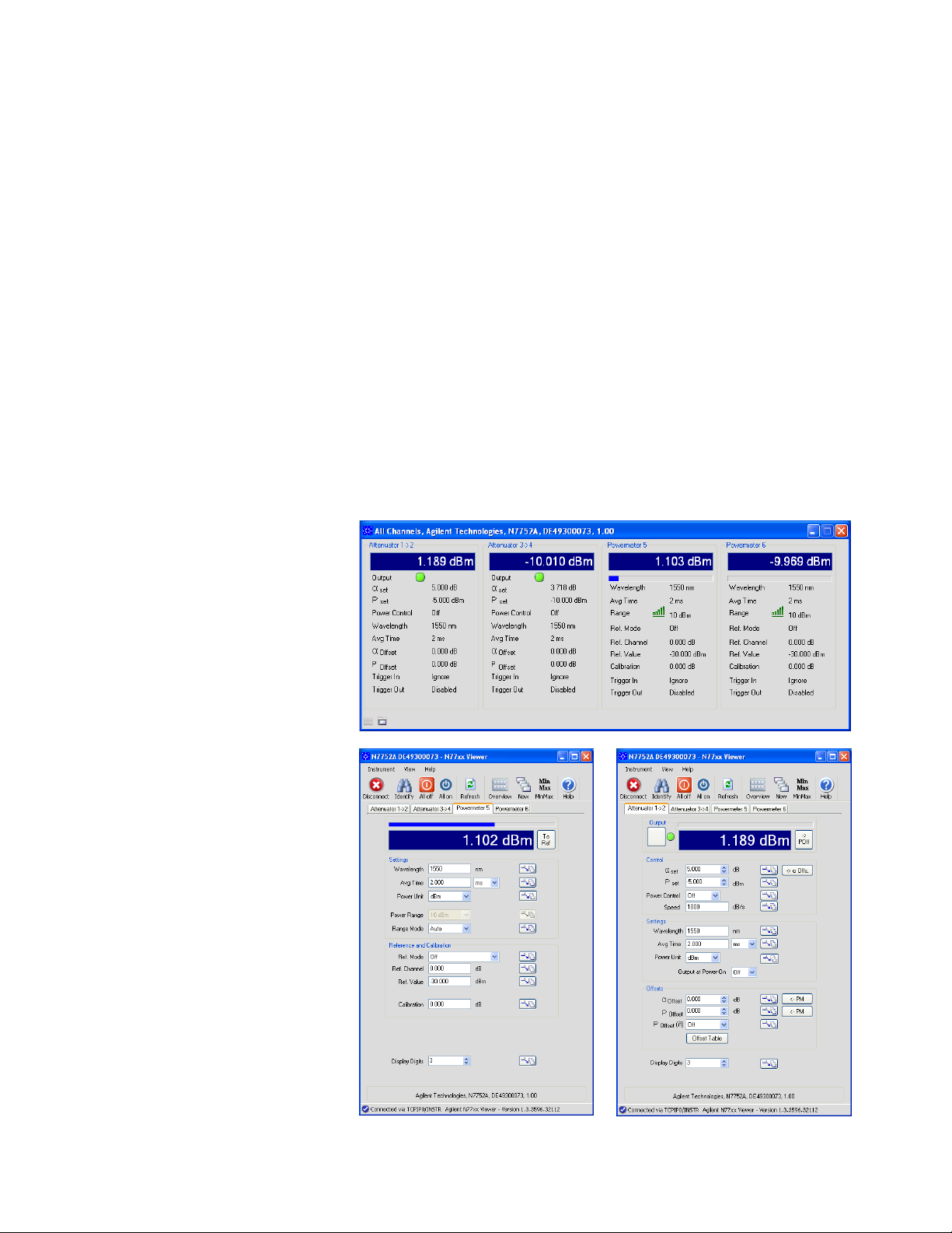
The N77xx-Viewer: An
easy-to-use graphical
user interface
The N77xx Windows-based graphical
user interface offers flexible and
convenient control of the instrument.
• Easy switching between channels
with tabs.
• Overview window with all channels
at a glance.
• Two instrument configurations can
be stored and recalled.
• Enable or disable the attenuator’s
output with one click.
• Choose between setting an attenuation or an output power.
Applications
Optical transceiver testing
One of the challenges in testing transceivers is parallelization of bit-errorratio measurements for multiple-device
and multichannel device measurements. Sensitivity measurements
require fast and precise setting of
optical power levels in parallel at the
receiver inputs with settling times like
100 ms for improved throughput.
The very fast attenuation and power
setting response of the Agilent
N775xA and N776xA attenuators
allows simulation of many network
configurations in a short time. In the
path-blocking mode, fiber network
cuts are emulated. With the attenuation and power ramp feature, the
attenuation and/or the output power
is changed at a defined rate of 0.1
dB/s to 1000 dB/s. This feature
simulates slow and fast changes
in the fiber network for testing the
network management system.
Definitions
Generally, all specifications are valid
at the stated operating and measurement conditions and settings, with
uninterrupted line voltage.
Specifications (guaranteed) describe
warranted product performance that
is valid under the specified conditions. Specifications include guard
bands to account for the expected
statistical performance distribution,
measurement uncertainties changes
in performance due to environmental
changes and aging of components.
Typical values (characteristics)
describe the product performance
that is usually met but not guaranteed. Typical values are based on
data from a representative set of
instruments.
General characteristics give additional information for using the instrument. These are general descriptive
terms that do not imply a level of
performance.
Modal fidelity for multimode
fiber setups
Signals in multimode fibers are distributed over a range of mode groups that
can have different loss and delay in a
link. For dependable multimode transceiver testing, the instrument used to
set the power level should not change
this modal distribution. The bulk-optic
filter and collimated beam path of
Agilent multimode attenuators are
the best way to assure homogeneous
attenuation of all input modes and to
optimize stability.
Optical network integration
testing
When integrating and testing network
equipment to test network transmission performance and network management, including meshed networks
using ROADMs, attenuators represent
link spans between network nodes or
amplifier stages.
4
Page 5

Technical Specifications
Table 1. Single-mode fiber optical attenuators
N7751A, N7752A, N7761A, N7762A, N7764A
Connectivity FC/APC angled (Option -022) or
FC/PC straight (Option -021) contact connector interface
Fiber type 9/125 µm SMF 28
Wavelength range 1260 nm to 1640 nm
Attenuation range 0 dB to 40 dB (45 dB typ.)
Attenuation setting mode Power setting mode
Range 0 dB to 40 dB -50 dBm to +20 dBm
Resolution 0.01 dB 0.01 dB
Repeatability
Accuracy (uncertainty)
Relative accuracy (uncertainty)
Polarization dependent loss
Settling time typ. 20 ms
Insertion loss
Attenuation transition speed selectable from 0.1 to 1000 dB/s
Relative uncertainty of monitor power meter
Averaging time of monitor power meter 2 ms to 1 s
Return loss typ. 45 dB
Maximum safe input power +23 dBm if applied to input port; < +18 dBm if applied to output port
Optical path blocking typ. 45 dB
1
typ. +/- 0.05 dB for attenuation 0 dB to 30 dB
± 0.025 dB
typ. +/- 0.10 dB for attenuation 30 dB to 40 dB
1 – 3
typ. ± 0.10 dB for attenuation 0 dB to 10 dB
typ. ± 0.15 dB for attenuation 10 dB to 20 dB
typ. ± 0.40 dB for attenuation 20 dB to 40 dB
1, 2, 4
5
typ. ≤ 0.15 dBPP for attenuation 0 dB to 10 dB
typ. ≤ 0.25 dBPP for attenuation 10 dB to 20 dB
± 0.05 dB ± 300 pW
≤ 0.15 dBPP
6
typ. ≤ 0.5 dBPP for attenuation 20 dB to 40 dB
7
8
typ. ≤ 1.2 dB (excluding connectors)
typ. 100 ms
≤ 2.2 dB (including connectors)
2, 10
± 0.05 dB ± 300 pW
6
9
1. At constant operating conditions.
2. For unpolarized light. Temperature constant and between (23 ± 5) °C.
3. For (1310 ± 15) nm, (1490 ± 10) nm and (1550 ± 15) nm.
4. Output power > -40 dBm, input power < +10 dBm.
For input power > +10 dBm add typ. ± 0.02 dB.
5. For (1550 ± 15) nm. Add typ. 0.05 dB for (1310 ± 15) nm and (1490 ± 10) nm.
6. Output power > -30 dBm, input power < +10 dBm.
7. For 20 dB step.
8. For (1550 ± 15) nm. Add typ. 0.20 dB for (1310 ± 15) nm and (1490 ± 10) nm.
9. Measured with Agilent reference connectors.
10. For (1550 ± 15) nm.
5
Page 6

Technical Specifications (continued)
Table 2 Multimode fiber optical attenuators
N7766A and N7768A
Connectivity FC/PC straight contact connector interface
Fiber type 50/125 µm (Option 050) or 62.5/125 µm (Option 062) MMF
Wavelength range 800 nm to 1370 nm
Attenuation range 0 dB to 35 dB
Attenuation setting mode Power setting mode
Range 0 dB to 35 dB -35 dBm to +20 dBm
Resolution 0.03 dB 0.03 dB
2, 5, 7
1, 2, 5
1 – 5
1 – 5
± 0.025 dB ± 0.025 dB
± 0.25 dB; typ. ± 0.15 dB
1 – 6
± 0.1 dB
≤ 2.0 dB; typ. ≤ 1.3 dB
1 – 6
± 0.1 dB
typ. 25 dB
3, 8
+23 dBm
Repeatability
Accuracy (uncertainty)
Relative accuracy (uncertainty)
Settling time (for 20 dB step) typ. 200 ms typ. 200 ms
Insertion loss
Attenuation transition speed selectable from 0.1 to 80 and 1000 dB/s
Relative uncertainty of monitor power meter
Averaging time of monitor power meter 2 ms to 1 s
Return loss
Maximum safe input power
Optical path blocking typ. 60 dB
1. At constant operating conditions.
2. Effective spectral bandwidth of input signal > 30 nm.
3. For mode launch conditions from IEEE 802.3: encircled flux < 30% in 4.5 µm radius and > 86% inside 19 µm for 50/125 µm fiber; < 25% inside
4.5 µm and > 75% inside 15 µm for 62.5/125 µm fiber.
4. For unpolarized light. Temperature constant and within (23 ± 5) °C.
5. For (850 ± 15) nm and (1310 ± 15) nm; for (1060 ± 15) nm, add typ. ± 0.1 dB to accuracy (uncertainty), relative accuracy (uncertainty) and relative
uncertainty of monitor power meter and add typ. 0.5 dB to insertion loss.
6. For 2 ms averaging time. Output power > -30 dBm, input power < +10 dBm, attenuation setting ≤ 30 dB.
7. The return loss is primarily limited by the return loss of the front-panel connections.
8. Agilent assumes no responsibility for damage caused by scratched or poorly cleaned connectors.
6
Page 7

Technical Specifications (continued)
Table 3. Optical power meter
N7751A and N7752A
Sensor element InGaAs
Wavelength range 1260 nm to 1640 nm
Specification wavelength range (1310 ± 15) nm, (1490 ± 10) nm, (1550 ± 15) nm
Power range -80 dBm to +10 dBm
Maximum safe power +16 dBm
Averaging time 2 ms to 1s
Applicable fiber type Standard SM and MM ≤ 62.5 µm core size, NA ≤ 0.24
Uncertainty at reference conditions
Total uncertainty
2, 5, 6
Linearity 7
at (23 ± 5)°C
over operating temperature
Polarization dependent responsivity (PDR)
Spectral ripple (due to interference)
Drift (dark) 4 ± 9 pW
Noise pp (dark) 3, (1s averaging time, 300s observation time) < 7 pWpp
Return loss 9 typ. > 57 dB
1, 3
± 2.5%
± 4.5%
± 0.02 dB
± 0.04 dB
3, 8
typ. < ± 0.01 dB (1260 nm to 1580 nm)
10
typ. < ± 0.01 dB
1. Reference conditions:
Single mode fiber SMF 9 µm. Power Level: -20 dBm to 0 dBm.
On day of calibration (add ± 0.3% for aging over one year; add ± 0.6% for aging over two years).
Spectral width of source < 10 nm FWHM.
Wavelength setting of power sensor corresponds to source wavelength ± 0.4 nm.
2. Operating conditions:
Single mode fiber SMF. For multimode fiber, typical.
Within one year of calibration; add ± 0.3% for second year.
Spectral width of source < 10 nm FWHM.
Wavelength setting of power sensor corresponds to source wavelength ± 0.4 nm.
3. Ambient temperature (23 ± 5) °C.
4. Temperature constant within ± 1 K after zeroing.
5. Excluding noise and offset drift.
6. Power range -60 dBm to +10 dBm.
7. Power range -40 dBm to +10 dBm. For power < -40 dBm add 0.05 dB.
8. Straight connector, SMF.
9. Angled connector 8°, ceramic ferrule, SMF.
10. For constant state of polarization, source linewidth < 100 MHz, angled connector 8°, wavelength range 1260 nm to 1625 nm. Add ± 0.01 dB typ.
within specification wavelength range for straight connector with ceramic ferrule.
7
Page 8

General Characteristics
Ordering Information
Dimensions (H x W x D):
1U half-rack
372 mm x 212 mm x 43 mm
for N7766A and N7768A
460 mm x 212 mm x 43 mm
(excluding front and back rubber
cushions)
Weight:
Approx. 3 kg
Recommended recalibration period
24 month
Operating temperature
+5 °C to +40 °C
Operating humidity
15% to 95%, non-condensing
Altitude
The maximum operating altitude is
2000 m.
Pollution protection
The Agilent N775xA/6xA is designed
for pollution degree 2.
Warm-up time
20 minutes
All systems have 1 year warranty
Model number
N7751A Optical Attenuator (1 Channel) with
Optical Power Meter (2 Channels)
N7752A Optical Attenuator (2 Channels) with
Optical Power Meter (2 Channels)
N7761A Optical Attenuator (1 Channel)
N7762A Optical Attenuator (2 Channels)
N7764A Optical Attenuator (4 Channels)
N7766A Optical Attenuator (2 Channels Multimode)
N7768A Optical Attenuator (4 Channels Multimode)
Connector interface option
-021 Straight contact connector (N7751A, N7752A, N7761A,
N7762A, N7764A)
-022 Angled contact connector (N7751A, N7752A, N7761A,
N7762A, N7764A)
-050 50/125 µm MMF Interface (N7766A, N7768A)
-062 62.5/125 µm MMF Interface (N7766A, N7768A)
Accessories
N7744-100 Rack Mount Kit for 1 or 2 Units
Warranty
All systems have 1 year warranty
R-51B-001-3C 1 year Return-to-Agilent warranty extended to 3 years
R-51B-001-5C 1 year Return-to-Agilent warranty extended to 5 years
Calibration
R-50C-011-3 Agilent calibration upfront support plan 3 year coverage
R-50C-011-5 Agilent calibration upfront support plan 5 year coverage
Interfaces
The instruments can be controlled via
LAN, USB or GPIB interfaces
Power consumption
Line power: AC 100 - 240 V ± 10%,
50/60 Hz, 60 VA max.
8
Page 9

www.agilent.com
www.agilent.com/find/voa
Agilent Email Updates
www.agilent.com/find/emailupdates
Get the latest information on the
products and applications you select.
Agilent Direct
www.agilent.com/find/emailupdates
Quickly choose and use your test
equipment solutions with confidence.
www.lxistandard.org
LXI is the LAN-based successor to
GPIB, providing faster, more efficient
connectivity. Agilent is a founding
member of the LXI consortium.
Agilent Channel Partners
www.agilent.com/find/channelpartners
Get the best of both worlds: Agilent’s
measurement expertise and product
breadth, combined with channel
partner convenience.
Agilent Advantage Services is committed to your success throughout
your equipment’s lifetime. We share
measurement and service expertise
to help you create the products that
change our world. To keep you competitive, we continually invest in tools
and processes that speed up calibration and repair, reduce your cost of
ownership, and move us ahead of
your development curve.
www.agilent.com/find/advantageservices
www.agilent.com/quality
For more information on Agilent
Technologies’ products, applications or
services, please contact your local Agilent
office. The complete list is available at:
www.agilent.com/find/contactus
Americas
Canada (877) 894 4414
Brazil (11) 4197 3500
Latin America 305 269 7500
Mexico 01800 5064 800
United States (800) 829 4444
Asia Pacific
Australia 1 800 629 485
China 800 810 0189
Hong Kong 800 938 693
India 1 800 112 929
Japan 0120 (421) 345
Korea 080 769 0800
Malaysia 1 800 888 848
Singapore 1 800 375 8100
Taiwan 0800 047 866
Thailand 1 800 226 008
Europe & Middle East
Austria 43 (0) 1 360 277 1571
Belgium 32 (0) 2 404 93 40
Denmark 45 70 13 15 15
Finland 358 (0) 10 855 2100
France 0825 010 700*
*0.125 €/minute
Germany 49 (0) 7031 464 6333
Ireland 1890 924 204
Israel 972-3-9288-504/544
Italy 39 02 92 60 8484
Netherlands 31 (0) 20 547 2111
Spain 34 (91) 631 3300
Sweden 0200-88 22 55
Switzerland 0800 80 53 53
United Kingdom 44 (0) 118 9276201
Other European Countries:
www.agilent.com/find/contactus
Revised: July 8, 2010
Product specifications and descriptions
in this document subject to change
without notice.
© Agilent Technologies, Inc. 2010
Printed in USA, October 4, 2010
5990-4394EN
 Loading...