

Page 1

Agilent Technologies 8935 Series E6381A
TDMA Base Station Test Set
GPIB Syntax Reference Guide
Firmware Version: A.02.01 and above
Agilent Part Number E6381-90014
Revision D
Printed in UK
January 2001
Page 2

Notice
Information contained in this document is subject to change without
notice.
All Rights Reserved. Reproduct i on, adaptation, or translation without
prior written permission is prohibited, except as allowed under the
copyright laws.
This material may be reproduced by or for the U.S. Government
pursuant to the Copyright License under the clause a t DFARS
52.227-7013 (APR 1988).
© Copyright 1999 - 2001 Agilent Technologies All Rights Reserved
2
Page 3

Contents
1. General Information
Manufacturer's Declaration. . . . . . . . . . . . . . . . . . . . . . . . . . . . . . . . . . . . . . . . . . . . . . . . . . . . 22
Safety Considerations . . . . . . . . . . . . . . . . . . . . . . . . . . . . . . . . . . . . . . . . . . . . . . . . . . . . . . . . 23
Safety Considerations for This Instrument. . . . . . . . . . . . . . . . . . . . . . . . . . . . . . . . . . . . . . 24
Product Markings. . . . . . . . . . . . . . . . . . . . . . . . . . . . . . . . . . . . . . . . . . . . . . . . . . . . . . . . . . . . 28
Certification . . . . . . . . . . . . . . . . . . . . . . . . . . . . . . . . . . . . . . . . . . . . . . . . . . . . . . . . . . . . . . . . 29
Agilent Technologies Warranty Statement for Commercial Products. . . . . . . . . . . . . . . . . . . 31
Assistance. . . . . . . . . . . . . . . . . . . . . . . . . . . . . . . . . . . . . . . . . . . . . . . . . . . . . . . . . . . . . . . . . . 33
Documentation . . . . . . . . . . . . . . . . . . . . . . . . . . . . . . . . . . . . . . . . . . . . . . . . . . . . . . . . . . . . . . 35
Conventions Used in This Manual. . . . . . . . . . . . . . . . . . . . . . . . . . . . . . . . . . . . . . . . . . . . . 35
Which Document is Required? . . . . . . . . . . . . . . . . . . . . . . . . . . . . . . . . . . . . . . . . . . . . . . . . 35
Trademark Acknowledgements . . . . . . . . . . . . . . . . . . . . . . . . . . . . . . . . . . . . . . . . . . . . . . . . . 36
2. GPIB Command Dictionary
Notice . . . . . . . . . . . . . . . . . . . . . . . . . . . . . . . . . . . . . . . . . . . . . . . . . . . . . . . . . . . . . . . . . . . . . 38
Using This Dictionary . . . . . . . . . . . . . . . . . . . . . . . . . . . . . . . . . . . . . . . . . . . . . . . . . . . . . . . . 39
Description of Commands. . . . . . . . . . . . . . . . . . . . . . . . . . . . . . . . . . . . . . . . . . . . . . . . . . . . 39
AFANalyzer subsystem . . . . . . . . . . . . . . . . . . . . . . . . . . . . . . . . . . . . . . . . . . . . . . . . . . . . . . . 40
:AIN <string>
:AIN? . . . . . . . . . . . . . . . . . . . . . . . . . . . . . . . . . . . . . . . . . . . . . . . . . . . . . . . . . . . . . . . . . . . . 40
:DEMPhasis <string>
:DEMPhasis? . . . . . . . . . . . . . . . . . . . . . . . . . . . . . . . . . . . . . . . . . . . . . . . . . . . . . . . . . . . . . . 40
:DEMPhasis:GAIN <str in g >
:DEMPhasis:GAIN? . . . . . . . . . . . . . . . . . . . . . . . . . . . . . . . . . . . . . . . . . . . . . . . . . . . . . . . . 41
:DETector <string>
:DETector? . . . . . . . . . . . . . . . . . . . . . . . . . . . . . . . . . . . . . . . . . . . . . . . . . . . . . . . . . . . . . . . . 42
:DETector:PKLocation <string>
:DETector:PKLocation?. . . . . . . . . . . . . . . . . . . . . . . . . . . . . . . . . . . . . . . . . . . . . . . . . . . . . . 42
:DETector:SETTling <string>
:DETector:SETTling? . . . . . . . . . . . . . . . . . . . . . . . . . . . . . . . . . . . . . . . . . . . . . . . . . . . . . . . 43
:ELResistor <real number>
:ELResistor? . . . . . . . . . . . . . . . . . . . . . . . . . . . . . . . . . . . . . . . . . . . . . . . . . . . . . . . . . . . . . . 43
:FILT1|FILTER1 <string>
:FILT1?|FILTER1? . . . . . . . . . . . . . . . . . . . . . . . . . . . . . . . . . . . . . . . . . . . . . . . . . . . . . . . . . 44
:FILT2|FILTER2 <string>
:FILT2?|FILTER2? . . . . . . . . . . . . . . . . . . . . . . . . . . . . . . . . . . . . . . . . . . . . . . . . . . . . . . . . . 44
:GTIMe <real num be r>
:GTIMe? . . . . . . . . . . . . . . . . . . . . . . . . . . . . . . . . . . . . . . . . . . . . . . . . . . . . . . . . . . . . . . . . . . 45
:INPut <str ing>
:INPut?. . . . . . . . . . . . . . . . . . . . . . . . . . . . . . . . . . . . . . . . . . . . . . . . . . . . . . . . . . . . . . . . . . . 45
:INPut:GAIN <string>
:INPut:GAIN? . . . . . . . . . . . . . . . . . . . . . . . . . . . . . . . . . . . . . . . . . . . . . . . . . . . . . . . . . . . . . 46
:NOTCh:GAIN <string>
:NOTCh:GAIN? . . . . . . . . . . . . . . . . . . . . . . . . . . . . . . . . . . . . . . . . . . . . . . . . . . . . . . . . . . . . 47
:NOTCh:FREQuency <real number>
:NOTCh:FREQuency?. . . . . . . . . . . . . . . . . . . . . . . . . . . . . . . . . . . . . . . . . . . . . . . . . . . . . . . 47
:RANGing <string>
:RANGing?. . . . . . . . . . . . . . . . . . . . . . . . . . . . . . . . . . . . . . . . . . . . . . . . . . . . . . . . . . . . . . . . 48
:SMPoint <string>
3
Page 4

Contents
:SMPoint? . . . . . . . . . . . . . . . . . . . . . . . . . . . . . . . . . . . . . . . . . . . . . . . . . . . . . . . . . . . . . . . . .48
:SPEaker:MODE <string>
:SPEaker:MODE?. . . . . . . . . . . . . . . . . . . . . . . . . . . . . . . . . . . . . . . . . . . . . . . . . . . . . . . . . . .48
:SPEaker:VOLume <string>
:SPEaker:VOLume? . . . . . . . . . . . . . . . . . . . . . . . . . . . . . . . . . . . . . . . . . . . . . . . . . . . . . . . . . 49
AFG1|AFGENERATOR1 subsystem. . . . . . . . . . . . . . . . . . . . . . . . . . . . . . . . . . . . . . . . . . . . .50
:AM <real number>
:AM? . . . . . . . . . . . . . . . . . . . . . . . . . . . . . . . . . . . . . . . . . . . . . . . . . . . . . . . . . . . . . . . . . . . . .50
:DESTination <string>
:DESTination? . . . . . . . . . . . . . . . . . . . . . . . . . . . . . . . . . . . . . . . . . . . . . . . . . . . . . . . . . . . . .50
:FM <real number>
:FM?. . . . . . . . . . . . . . . . . . . . . . . . . . . . . . . . . . . . . . . . . . . . . . . . . . . . . . . . . . . . . . . . . . . . . .51
:FREQuency <real number>
:FREQuency? . . . . . . . . . . . . . . . . . . . . . . . . . . . . . . . . . . . . . . . . . . . . . . . . . . . . . . . . . . . . . .51
:OUTPut <real number>
:OUTPut? . . . . . . . . . . . . . . . . . . . . . . . . . . . . . . . . . . . . . . . . . . . . . . . . . . . . . . . . . . . . . . . . .52
AFG2|ENCoder subsystem . . . . . . . . . . . . . . . . . . . . . . . . . . . . . . . . . . . . . . . . . . . . . . . . . . . .53
:AM <real number>
:AM? . . . . . . . . . . . . . . . . . . . . . . . . . . . . . . . . . . . . . . . . . . . . . . . . . . . . . . . . . . . . . . . . . . . . .53
:BURSt <i nt eger>
:BURSt?. . . . . . . . . . . . . . . . . . . . . . . . . . . . . . . . . . . . . . . . . . . . . . . . . . . . . . . . . . . . . . . . . . .53
:DESTination <string>
:DESTination? . . . . . . . . . . . . . . . . . . . . . . . . . . . . . . . . . . . . . . . . . . . . . . . . . . . . . . . . . . . . .54
:FILTer <string>
:FILTer?. . . . . . . . . . . . . . . . . . . . . . . . . . . . . . . . . . . . . . . . . . . . . . . . . . . . . . . . . . . . . . . . . . .55
:FILTer:MODE <string>
:FILTer:MODE? . . . . . . . . . . . . . . . . . . . . . . . . . . . . . . . . . . . . . . . . . . . . . . . . . . . . . . . . . . . . 56
:FM <real number>
:FM?. . . . . . . . . . . . . . . . . . . . . . . . . . . . . . . . . . . . . . . . . . . . . . . . . . . . . . . . . . . . . . . . . . . . . .56
:FREQuency <real number>
:FREQuency? . . . . . . . . . . . . . . . . . . . . . . . . . . . . . . . . . . . . . . . . . . . . . . . . . . . . . . . . . . . . . .57
:MODE <string>. . . . . . . . . . . . . . . . . . . . . . . . . . . . . . . . . . . . . . . . . . . . . . . . . . . . . . . . . . . . 57
:OUTPut <real number>
:OUTPut? . . . . . . . . . . . . . . . . . . . . . . . . . . . . . . . . . . . . . . . . . . . . . . . . . . . . . . . . . . . . . . . . .58
:PEMPhasis <strin g>
:PEMPhasis?. . . . . . . . . . . . . . . . . . . . . . . . . . . . . . . . . . . . . . . . . . . . . . . . . . . . . . . . . . . . . . .58
:POLarity <string>
:POLarity?. . . . . . . . . . . . . . . . . . . . . . . . . . . . . . . . . . . . . . . . . . . . . . . . . . . . . . . . . . . . . . . . .59
:SEND:MODE <string>
:SEND:MODE?. . . . . . . . . . . . . . . . . . . . . . . . . . . . . . . . . . . . . . . . . . . . . . . . . . . . . . . . . . . . .59
:SEND . . . . . . . . . . . . . . . . . . . . . . . . . . . . . . . . . . . . . . . . . . . . . . . . . . . . . . . . . . . . . . . . . . .60
:STOP . . . . . . . . . . . . . . . . . . . . . . . . . . . . . . . . . . . . . . . . . . . . . . . . . . . . . . . . . . . . . . . . . . . .60
:AMPS|TACS:BUSY <string>
:AMPS|TACS:BUSY? . . . . . . . . . . . . . . . . . . . . . . . . . . . . . . . . . . . . . . . . . . . . . . . . . . . . . . .61
:AMPS|TACS:BUSY:DELay <integer> . . . . . . . . . . . . . . . . . . . . . . . . . . . . . . . . . . . . . . . . .62
:AMPS|TACS:CHANnel <string>
:AMPS|TACS:CHANnel?. . . . . . . . . . . . . . . . . . . . . . . . . . . . . . . . . . . . . . . . . . . . . . . . . . . . .62
:AMPS|TACS:DATA:AM <real number>
:AMPS|TACS:DATA:AM? . . . . . . . . . . . . . . . . . . . . . . . . . . . . . . . . . . . . . . . . . . . . . . . . . . . .63
4
Page 5

Contents
:AMPS|TACS:DATA:FM <real number>
:AMPS|TACS:DATA:FM?. . . . . . . . . . . . . . . . . . . . . . . . . . . . . . . . . . . . . . . . . . . . . . . . . . . . 63
:AMPS|TACS:DATA:LEVel <real number>
:AMPS|TACS:DATA:LEVel? . . . . . . . . . . . . . . . . . . . . . . . . . . . . . . . . . . . . . . . . . . . . . . . . . 64
:AMPS|TACS:DATA:RATE <real number> . . . . . . . . . . . . . . . . . . . . . . . . . . . . . . . . . . . . . 64
:AMPS|TACS:FILLer:DATA1 <string>
:AMPS|TACS:FILLer:DATA2 <string>
:AMPS|TACS:FILLer:DATA1?
:AMPS|TACS:FILLer:DATA2?. . . . . . . . . . . . . . . . . . . . . . . . . . . . . . . . . . . . . . . . . . . . . . . . 65
:AMPS|TACS:FILLer:SEND . . . . . . . . . . . . . . . . . . . . . . . . . . . . . . . . . . . . . . . . . . . . . . . . . 65
:AMPS|TACS:FILLer:STOP . . . . . . . . . . . . . . . . . . . . . . . . . . . . . . . . . . . . . . . . . . . . . . . . . 66
:AMPS|TACS:FVCMessage <string>
:AMPS|TACS:FVCMessage? . . . . . . . . . . . . . . . . . . . . . . . . . . . . . . . . . . . . . . . . . . . . . . . . . 66
:AMPS|TACS:MESSage:DATA1 <string>
:AMPS|TACS:MESSage:DATA2 <string>
:AMPS|TACS:MESSage:DATA1?
:AMPS|TACS:MESSage:DATA2? . . . . . . . . . . . . . . . . . . . . . . . . . . . . . . . . . . . . . . . . . . . . . 67
:AMPS|TACS:SAT:AM <real number>
:AMPS|TACS:SAT:AM? . . . . . . . . . . . . . . . . . . . . . . . . . . . . . . . . . . . . . . . . . . . . . . . . . . . . . 67
:AMPS|TACS:SAT:FM <real number>
:AMPS|TACS:SAT:FM? . . . . . . . . . . . . . . . . . . . . . . . . . . . . . . . . . . . . . . . . . . . . . . . . . . . . . 68
:AMPS|TACS:SAT:LEVel <real number>
:AMPS|TACS:SAT:LEVel. . . . . . . . . . . . . . . . . . . . . . . . . . . . . . . . . . . . . . . . . . . . . . . . . . . . 68
:AMPS|TACS:SAT:FREQuency <real number> . . . . . . . . . . . . . . . . . . . . . . . . . . . . . . . . . . 69
:AMPS|TACS:STANdard <string>
:AMPS|TACS:STANdard? . . . . . . . . . . . . . . . . . . . . . . . . . . . . . . . . . . . . . . . . . . . . . . . . . . . 69
:DTMF:FREQuency:COLumn <multiple real number>
:DTMF:FREQuency:COLumn?. . . . . . . . . . . . . . . . . . . . . . . . . . . . . . . . . . . . . . . . . . . . . . . . 70
:DTMF:FREQuency:ROW <multiple real number>
:DTMF:FREQuency:ROW?. . . . . . . . . . . . . . . . . . . . . . . . . . . . . . . . . . . . . . . . . . . . . . . . . . . 70
:DTMF:OFFTime <real number>
:DTMF:OFFTime?. . . . . . . . . . . . . . . . . . . . . . . . . . . . . . . . . . . . . . . . . . . . . . . . . . . . . . . . . . 70
:DTMF:ONTime <real number>
:DTMF:ONTime?. . . . . . . . . . . . . . . . . . . . . . . . . . . . . . . . . . . . . . . . . . . . . . . . . . . . . . . . . . . 71
:DTMF:SEQuence <string>
:DTMF:SEQuence? . . . . . . . . . . . . . . . . . . . . . . . . . . . . . . . . . . . . . . . . . . . . . . . . . . . . . . . . . 71
:DTMF:STANdard <string>
:DTMF:STANdard? . . . . . . . . . . . . . . . . . . . . . . . . . . . . . . . . . . . . . . . . . . . . . . . . . . . . . . . . . 71
:DTMF:TWISt <real number>
:DTMF:TWISt? . . . . . . . . . . . . . . . . . . . . . . . . . . . . . . . . . . . . . . . . . . . . . . . . . . . . . . . . . . . . 72
:FGENerator:SUNits <string>
:FGENerator:SUNits?. . . . . . . . . . . . . . . . . . . . . . . . . . . . . . . . . . . . . . . . . . . . . . . . . . . . . . . 72
:FGENerator:WAVeform <string>
:FGENerator:WAVeform? . . . . . . . . . . . . . . . . . . . . . . . . . . . . . . . . . . . . . . . . . . . . . . . . . . . . 73
:NAMPs|NTACs:BUSY <string>
:NAMPs|NTACs:BUSY?. . . . . . . . . . . . . . . . . . . . . . . . . . . . . . . . . . . . . . . . . . . . . . . . . . . . . 74
:NAMPs|NTACs:BUSY:DELay <integer>. . . . . . . . . . . . . . . . . . . . . . . . . . . . . . . . . . . . . . . 75
:NAMPs|NTACs:CHANnel <string>
:NAMPs|NTACs:CHANnel?. . . . . . . . . . . . . . . . . . . . . . . . . . . . . . . . . . . . . . . . . . . . . . . . . . 75
5
Page 6

Contents
:NAMPs|NTACs:DSAT:MESS <string>
:NAMPs|NTACs:DSAT:MESS?. . . . . . . . . . . . . . . . . . . . . . . . . . . . . . . . . . . . . . . . . . . . . . . .76
:NAMPs|NTACs:DSAT:SEND <string> . . . . . . . . . . . . . . . . . . . . . . . . . . . . . . . . . . . . . . . . .76
:NAMPs|NTACs:DSAT:STOP. . . . . . . . . . . . . . . . . . . . . . . . . . . . . . . . . . . . . . . . . . . . . . . . .77
:NAMPs|NTACs[:FOCC]:AM <real number>
:NAMPs|NTACs[:FOCC]:AM? . . . . . . . . . . . . . . . . . . . . . . . . . . . . . . . . . . . . . . . . . . . . . . . .77
:NAMPs|NTACs[:FOCC]:FM <real number>
:NAMPs|NTACs[:FOCC]:FM?. . . . . . . . . . . . . . . . . . . . . . . . . . . . . . . . . . . . . . . . . . . . . . . . .77
:NAMPs|NTACs[:FOCC]:LEVel <real number>
:NAMPs|NTACs[:FOCC]:LEVel? . . . . . . . . . . . . . . . . . . . . . . . . . . . . . . . . . . . . . . . . . . . . . .78
:NAMPs|NTACs[:FOCC]:RATE <real number>
:NAMPs|NTACs[:FOCC]:RATE? . . . . . . . . . . . . . . . . . . . . . . . . . . . . . . . . . . . . . . . . . . . . . .78
:NAMPs|NTACs[:FOCC]:FILLer:DATA1 <string>
:NAMPs|NTACs[:FOCC]:FILLer:DATA2 <string>
:NAMPs|NTACs[:FOCC]:FILLer:DATA1?
:NAMPs|NTACs[:FOCC]:FILLer:DATA2? . . . . . . . . . . . . . . . . . . . . . . . . . . . . . . . . . . . . . . .79
:NAMPs|NTACs[:FOCC]:FILLer:SEND . . . . . . . . . . . . . . . . . . . . . . . . . . . . . . . . . . . . . . . .79
:NAMPs|NTACs[:FOCC]:FILLer:STOP . . . . . . . . . . . . . . . . . . . . . . . . . . . . . . . . . . . . . . . .80
:NAMPS|NTACS[:FOCC]:MESSage:DATA1 <string>
:NAMPS|NTACS[:FOCC]:MESSage:DATA2 <string>
:NAMPS|NTACS[:FOCC]:MESSage:DATA1?
:NAMPS|NTACS[:FOCC]:MESSage:DATA2? . . . . . . . . . . . . . . . . . . . . . . . . . . . . . . . . . . . .80
:NAMPs|NTACs:FVC:MESS <string>
:NAMPs|NTACs:FVC:MESS?. . . . . . . . . . . . . . . . . . . . . . . . . . . . . . . . . . . . . . . . . . . . . . . . .81
:NAMPs|NTACs:FVC:RATE <real number>
:NAMPs|NTACs:FVC:RATE? . . . . . . . . . . . . . . . . . . . . . . . . . . . . . . . . . . . . . . . . . . . . . . . . .81
:NAMPs|NTACs:FVC:AM <real number>
:NAMPs|NTACs:FVC:AM? . . . . . . . . . . . . . . . . . . . . . . . . . . . . . . . . . . . . . . . . . . . . . . . . . . .82
:NAMPs|NTACs:FVC:FM <real number>
:NAMPs|NTACs:FVC:FM? . . . . . . . . . . . . . . . . . . . . . . . . . . . . . . . . . . . . . . . . . . . . . . . . . . .82
:NAMPs|NTACs:FVC:LEVel <real number>
:NAMPs|NTACs:FVC:LEVel? . . . . . . . . . . . . . . . . . . . . . . . . . . . . . . . . . . . . . . . . . . . . . . . . .83
:NAMPs|NTACs:SEND
:NAMPs|NTACs:SEND? . . . . . . . . . . . . . . . . . . . . . . . . . . . . . . . . . . . . . . . . . . . . . . . . . . . . .83
:NAMPS|NTACS:STANdard <string>
:NAMPS|NTACS:STANdard?. . . . . . . . . . . . . . . . . . . . . . . . . . . . . . . . . . . . . . . . . . . . . . . . .84
CDPD subsystem. . . . . . . . . . . . . . . . . . . . . . . . . . . . . . . . . . . . . . . . . . . . . . . . . . . . . . . . . . . . .85
CONFigure subsystem . . . . . . . . . . . . . . . . . . . . . . . . . . . . . . . . . . . . . . . . . . . . . . . . . . . . . . . .86
:BADDress <integer >
:BADDerss?. . . . . . . . . . . . . . . . . . . . . . . . . . . . . . . . . . . . . . . . . . . . . . . . . . . . . . . . . . . . . . . .86
:BEEPer <string>
:BEEPer?. . . . . . . . . . . . . . . . . . . . . . . . . . . . . . . . . . . . . . . . . . . . . . . . . . . . . . . . . . . . . . . . . .86
:BMODe <string>
:BMODe?. . . . . . . . . . . . . . . . . . . . . . . . . . . . . . . . . . . . . . . . . . . . . . . . . . . . . . . . . . . . . . . . . .87
:DISPlay:MESSages
:DISPlay:MESSages? . . . . . . . . . . . . . . . . . . . . . . . . . . . . . . . . . . . . . . . . . . . . . . . . . . . . . . . .87
:DATE <integer>
:DATE? . . . . . . . . . . . . . . . . . . . . . . . . . . . . . . . . . . . . . . . . . . . . . . . . . . . . . . . . . . . . . . . . . . .87
:KNOB <string>
6
Page 7

Contents
:KNOB? . . . . . . . . . . . . . . . . . . . . . . . . . . . . . . . . . . . . . . . . . . . . . . . . . . . . . . . . . . . . . . . . . . 88
:NOTChmode <string>
:NOTChmode? . . . . . . . . . . . . . . . . . . . . . . . . . . . . . . . . . . . . . . . . . . . . . . . . . . . . . . . . . . . . . 88
:OFLevel:MODE <string>
:OFLevel:MODE? . . . . . . . . . . . . . . . . . . . . . . . . . . . . . . . . . . . . . . . . . . . . . . . . . . . . . . . . . . 88
:OFLevel:ANTenna <real number>
:OFLevel:ANTenna? . . . . . . . . . . . . . . . . . . . . . . . . . . . . . . . . . . . . . . . . . . . . . . . . . . . . . . . . 89
:OFLevel:DUPL ex <real number>
:OFLevel:DUPLex? . . . . . . . . . . . . . . . . . . . . . . . . . . . . . . . . . . . . . . . . . . . . . . . . . . . . . . . . . 89
:OFLevel:RFINout <real number>
:OFLevel:RFINout?. . . . . . . . . . . . . . . . . . . . . . . . . . . . . . . . . . . . . . . . . . . . . . . . . . . . . . . . . 90
:OFRequency <real number>
:OFRequency? . . . . . . . . . . . . . . . . . . . . . . . . . . . . . . . . . . . . . . . . . . . . . . . . . . . . . . . . . . . . . 90
:OMODe <string>
:OMODe? . . . . . . . . . . . . . . . . . . . . . . . . . . . . . . . . . . . . . . . . . . . . . . . . . . . . . . . . . . . . . . . . . 91
:OPERation:AUTO
:OPERation:HOLD . . . . . . . . . . . . . . . . . . . . . . . . . . . . . . . . . . . . . . . . . . . . . . . . . . . . . . . . . 91
:PCMCia:CARD:STATus? . . . . . . . . . . . . . . . . . . . . . . . . . . . . . . . . . . . . . . . . . . . . . . . . . . . . 91
:PCMCia:CARD:TYPE? . . . . . . . . . . . . . . . . . . . . . . . . . . . . . . . . . . . . . . . . . . . . . . . . . . . . . 92
:PCMCia:CARD:SIZE? . . . . . . . . . . . . . . . . . . . . . . . . . . . . . . . . . . . . . . . . . . . . . . . . . . . . . . 92
:PRINt:ADDRess <integer>
:PRINt:ADDRess? . . . . . . . . . . . . . . . . . . . . . . . . . . . . . . . . . . . . . . . . . . . . . . . . . . . . . . . . . . 92
:PRINt:LINes|LINE <integer>
:PRINt:LINes|LINE? . . . . . . . . . . . . . . . . . . . . . . . . . . . . . . . . . . . . . . . . . . . . . . . . . . . . . . . 93
:PRINt:DESTination|PORTs <string>
:PRINt:DESTination?|PORTs? . . . . . . . . . . . . . . . . . . . . . . . . . . . . . . . . . . . . . . . . . . . . . . . 93
:PRINt:FFSTart <string>
:PRINt:FFSTart?. . . . . . . . . . . . . . . . . . . . . . . . . . . . . . . . . . . . . . . . . . . . . . . . . . . . . . . . . . . 93
:PRINt:FFENd <string>
:PRINt:FFENd?. . . . . . . . . . . . . . . . . . . . . . . . . . . . . . . . . . . . . . . . . . . . . . . . . . . . . . . . . . . . 94
:PRINt:TITLe <string>
:PRINt:TITLe?. . . . . . . . . . . . . . . . . . . . . . . . . . . . . . . . . . . . . . . . . . . . . . . . . . . . . . . . . . . . . 94
:PRINt:PRINter|HPModel|HPMO <string>
:PRINt:PRINter|HPModel|HPMO? . . . . . . . . . . . . . . . . . . . . . . . . . . . . . . . . . . . . . . . . . . . 95
:REFerence:INPut:SELect <string>
:REFerence:INPut:SELect . . . . . . . . . . . . . . . . . . . . . . . . . . . . . . . . . . . . . . . . . . . . . . . . . . . 95
:REFerence:TDMA <string>
:REFerence:TDMA?. . . . . . . . . . . . . . . . . . . . . . . . . . . . . . . . . . . . . . . . . . . . . . . . . . . . . . . . . 96
:REFerence:SYNthesizer <string>
:REFerence:SYNthesizer?. . . . . . . . . . . . . . . . . . . . . . . . . . . . . . . . . . . . . . . . . . . . . . . . . . . . 96
:REFerence:PCM <string>
:REFerence:PCM? . . . . . . . . . . . . . . . . . . . . . . . . . . . . . . . . . . . . . . . . . . . . . . . . . . . . . . . . . . 97
:RFCStandard <string>
:RFCStandard? . . . . . . . . . . . . . . . . . . . . . . . . . . . . . . . . . . . . . . . . . . . . . . . . . . . . . . . . . . . . 98
:RFDisplay <str in g>
:RFDisplay? . . . . . . . . . . . . . . . . . . . . . . . . . . . . . . . . . . . . . . . . . . . . . . . . . . . . . . . . . . . . . . . 99
:RFIMped <string>
:RFIMPed?. . . . . . . . . . . . . . . . . . . . . . . . . . . . . . . . . . . . . . . . . . . . . . . . . . . . . . . . . . . . . . . . 99
:SPOR9|SPORT9|SB9|SP9:BAUD <string>
7
Page 8

Contents
:SPOR9|SPORT9|SB9|SP9:BAUD? . . . . . . . . . . . . . . . . . . . . . . . . . . . . . . . . . . . . . . . . . .100
:SPOR9|SPORT9|SB9|SP9:PARity <string>
:SPOR9|SPORT9|SB9|SP9:PARity?. . . . . . . . . . . . . . . . . . . . . . . . . . . . . . . . . . . . . . . . . .100
:SPOR9|SPORT9|SB9|SP9:DATA <string>
:SPOR9|SPORT9|SB9|SP9:DATA?. . . . . . . . . . . . . . . . . . . . . . . . . . . . . . . . . . . . . . . . . . . 101
:SPOR9|SPORT9| SB9|SP9:STOP <string>
:SPOR9|SPORT9|SB9|SP9:STOP?. . . . . . . . . . . . . . . . . . . . . . . . . . . . . . . . . . . . . . . . . . . 101
:SPOR9|SPORT9|SB9|SP9:FCONtrol|FLOW <string>
:SPOR9|SPORT9|SB9|SP9:FCONtrol|FLOW?. . . . . . . . . . . . . . . . . . . . . . . . . . . . . . . . .101
:SPOR9|SPORT9| SB9 |S P9: IBECh o <strin g >
:SPOR9|SPORT9|SB9|SP9:IBECho? . . . . . . . . . . . . . . . . . . . . . . . . . . . . . . . . . . . . . . . . .102
:SPOR9|SPORT9| SB9|SP9:IECHo <string>
:SPOR9|SPORT9|SB9|SP9:IECHo? . . . . . . . . . . . . . . . . . . . . . . . . . . . . . . . . . . . . . . . . . .102
:SPOR9|SPORT9|SB9|SP9:MODem:MODE <string>
:SPOR9|SPORT9|SB9|SP9:MODem:MODE? . . . . . . . . . . . . . . . . . . . . . . . . . . . . . . . . . .103
:SPOR9|SPORT9|SB9|SP9:MODem:CALL:ORIGinate . . . . . . . . . . . . . . . . . . . . . . . . . .103
:SPOR9|SPORT9|SB9|SP9:MODem:CALL:DISConnect . . . . . . . . . . . . . . . . . . . . . . . . .103
:SPOR9|SPORT9|SB9|SP9:MODem:CALL:STATus? . . . . . . . . . . . . . . . . . . . . . . . . . . . .104
:SPOR9|SPORT9|SB9|SP9:MODem:CONNect:NUMBer
:SPOR9|SPORT9|SB9|SP9:MODem:CONNect:NUMBer? . . . . . . . . . . . . . . . . . . . . . . . .104
:SPOR9|SPORT9|SB9|SP9:MODem:CONNect:TIMeout
:SPOR9|SPORT9|SB9|SP9:MODem:CONNect:TIMeout? . . . . . . . . . . . . . . . . . . . . . . . .104
:SPOR9|SPORT9|SB9|SP9:MODem:CONNect:HDELay
:SPOR9|SPORT9|SB9|SP9:MODem:CONNect:HDELay? . . . . . . . . . . . . . . . . . . . . . . . .105
:SPOR9|SPORT9|SB9|SP9:MODem:CONNect:RETRy
:SPOR9|SPORT9|SB9|SP9:MODem:CONNect:RETRy?. . . . . . . . . . . . . . . . . . . . . . . . . .105
:SPOR9|SPORT9|SB9|SP9:MODem:CONFigure:UPDate . . . . . . . . . . . . . . . . . . . . . . . .105
:SPOR9|SPORT9|SB9|SP9:MODem:CONFigure:STRing1
:SPOR9|SPORT9|SB9|SP9:MODem:CONFigure:STRing1?
:SPOR9|SPORT9|SB9|SP9:MODem:CONFigure:STRing2
:SPOR9|SPORT9|SB9|SP9:MODem:CONFigure:STRing2?
:SPOR9|SPORT9|SB9|SP9:MODem:CONFigure:STRing3
:SPOR9|SPORT9|SB9|SP9:MODem:CONFigure:STRing3?. . . . . . . . . . . . . . . . . . . . . . .106
:SPOR9|SPORT9|SB9|SP9:MODem:CONFigure:ECHaracter
:SPOR9|SPORT9|SB9|SP9:MODem:CONFigure:ECHaracter?. . . . . . . . . . . . . . . . . . . .106
:SPOR9|SPORT9|SB9|SP9:MODem:CONFigure:ECEQivalent?. . . . . . . . . . . . . . . . . . .107
:SPOR9|SPORT9|SB9|SP9:MODem:SECurity:STATe
:SPOR9|SPORT9|SB9|SP9:MODem:SECurity:STATe? . . . . . . . . . . . . . . . . . . . . . . . . . .107
:SPOR9|SPORT9|SB9|SP9:MODem:SECurity:PASSword
:SPOR9|SPORT9|SB9|SP9:MODem:SECurity:PASSword? . . . . . . . . . . . . . . . . . . . . . . .108
:SPOR9|SPORT9|SB9|SP9:SIN|SINP <string>
:SPOR9|SPORT9|SB9|SP9:SIN|SINP?. . . . . . . . . . . . . . . . . . . . . . . . . . . . . . . . . . . . . . .108
:SPOR9|SPORT9|SB9|SP9:STATus:LINE? . . . . . . . . . . . . . . . . . . . . . . . . . . . . . . . . . . . .108
:SPOR9|SPORT9|SB9|SP9:STATus:MODem?. . . . . . . . . . . . . . . . . . . . . . . . . . . . . . . . . .109
:SPOR10|SPORT10|SB10|SP10:BAUD <string>
:SPOR10|SPORT10|SB10|SP10:BAUD? . . . . . . . . . . . . . . . . . . . . . . . . . . . . . . . . . . . . . .109
:SPOR10|SPORT10|SB10|SP10 :PARity <string>
:SPOR10|SPORT10|SB10|SP10:PARity?. . . . . . . . . . . . . . . . . . . . . . . . . . . . . . . . . . . . . .109
:SPOR10|SPORT10|SB10|SP10:DATA <string>
8
Page 9

Contents
:SPOR10|SPORT10|SB10|SP10:DATA? . . . . . . . . . . . . . . . . . . . . . . . . . . . . . . . . . . . . . . 110
:SPOR10|SPORT10|SB10|SP10:STOP <string>
:SPOR10|SPORT10|SB10|SP10:STOP? . . . . . . . . . . . . . . . . . . . . . . . . . . . . . . . . . . . . . . 110
:SPOR10|SPOR T1 0|SB10|SP10:FCONt r ol| FL OW <string>
:SPOR10|SPORT10|SB10|SP10:FCONtrol|FLOW? . . . . . . . . . . . . . . . . . . . . . . . . . . . . 110
:SPOR10|SPORT10|SB10|SP10:STATus:LINE? . . . . . . . . . . . . . . . . . . . . . . . . . . . . . . . 111
:SPOR10|SPORT10|SB10|SP10:STATus:MODem? . . . . . . . . . . . . . . . . . . . . . . . . . . . . . 111
:SPOR10|SPORT10|SB10|SP10:MOD em:MODE <string>
:SPOR10|SPORT10|SB10|SP10:MODem:MODE?. . . . . . . . . . . . . . . . . . . . . . . . . . . . . . 111
:SPOR10|SPORT10|SB10|SP10:MODem:CALL:ORIGinate. . . . . . . . . . . . . . . . . . . . . . 112
:SPOR10|SPORT10|SB10|SP10:MODem:CALL:DISConnect. . . . . . . . . . . . . . . . . . . . . 112
:SPOR10|SPORT10|SB10|SP10:MODem:CALL:STATus?. . . . . . . . . . . . . . . . . . . . . . . . 112
:SPOR10|SPORT10|SB10|SP10:MODem:CONNect:NUMBer
:SPOR10|SPORT10|SB10|SP10:MODem:CONNect:NUMBer? . . . . . . . . . . . . . . . . . . . 113
:SPOR10|SPORT10|SB10|SP10:MODem:CONNect:TIMeout
:SPOR10|SPORT10|SB10|SP10:MODem:CONNect:TIMeout?. . . . . . . . . . . . . . . . . . . . 113
:SPOR10|SPORT10|SB10|SP10:MODem:CONNect:HDELay
:SPOR10|SPORT10|SB10|SP10:MODem:CONNect:HDELay?. . . . . . . . . . . . . . . . . . . . 113
:SPOR10|SPORT10|SB10|SP10:MODem:CONNect:RETRy
:SPOR10|SPORT10|SB10|SP10:MODem:CONNect:RETRy? . . . . . . . . . . . . . . . . . . . . . 114
:SPOR10|SPORT10|SB10|SP10:MODem:CONFigure:UPDate . . . . . . . . . . . . . . . . . . . 114
:SPOR10|SPORT10|SB10|SP10:MODem:CONFigure:STRing1
:SPOR10|SPORT10|SB10|SP10:MODem:CONFigure:STRing1?
:SPOR10|SPORT10|SB10|SP10:MODem:CONFigure:STRing2
:SPOR10|SPORT10|SB10|SP10:MODem:CONFigure:STRing2?
:SPOR10|SPORT10|SB10|SP10:MODem:CONFigure:STRing3
:SPOR10|SPORT10|SB10|SP10:MODem:CONFigure:STRing3? . . . . . . . . . . . . . . . . . . 115
:SPOR10|SPORT10|SB10|SP10:MODem:CONFigure:ECHaracter
:SPOR10|SPORT10|SB10|SP10:MODem:CONFigure:ECHaracter? . . . . . . . . . . . . . . . 115
:SPOR10|SPORT10|SB10|SP10:MODem:CONFigure:ECEQivalent? . . . . . . . . . . . . . . 116
:SPOR10|SPORT10|SB10|SP10:MODem:SECurity:STATe
:SPOR10|SPORT10|SB10|SP10:MODem:SECurity:STATe?. . . . . . . . . . . . . . . . . . . . . . 116
:SPOR10|SPORT10|SB10|SP10:MODem:SECurity:PASSword
:SPOR10|SPORT10|SB10|SP10:MODem:SECurity:PASSword? . . . . . . . . . . . . . . . . . . 117
:SPOR11|SPORT11|SB11|SP11:BAUD <string>
:SPOR11|SPORT11|SB11|SP11:BAUD? . . . . . . . . . . . . . . . . . . . . . . . . . . . . . . . . . . . . . . 117
:SPOR11|SPORT11|SB11|SP11:PARity <string>
:SPOR11|SPORT11|SB11|SP11:PARity? . . . . . . . . . . . . . . . . . . . . . . . . . . . . . . . . . . . . . 118
:SPOR11|SPORT11|SB11|SP11:DATA <string>
:SPOR11|SPORT11|SB11|SP11:DATA? . . . . . . . . . . . . . . . . . . . . . . . . . . . . . . . . . . . . . . 118
:SPOR11|SPORT11|SB11|SP11:STOP <string>
:SPOR11|SPORT11|SB11|SP11:STOP? . . . . . . . . . . . . . . . . . . . . . . . . . . . . . . . . . . . . . . 119
:SPOR11|SPORT11|SB11|SP11:FCONtrol|FLOW <string>
:SPOR11|SPORT11|SB11|SP11:FCONtrol|FLOW? . . . . . . . . . . . . . . . . . . . . . . . . . . . . 119
:SPOR11|SPORT11|SB11|SP11:STATus:LINE?. . . . . . . . . . . . . . . . . . . . . . . . . . . . . . . . 119
:SPOR11|SPORT11|SB11|SP11:STATus:MODem? . . . . . . . . . . . . . . . . . . . . . . . . . . . . . 120
:SPOR11|SPORT11|SB11|SP11:MODem:MODE <string>
:SPOR11|SPORT11|SB11|SP11:MODem:MODE? . . . . . . . . . . . . . . . . . . . . . . . . . . . . . . 120
:SPOR11|SPORT11|SB11|SP11:MODem:CALL:ORIGinate . . . . . . . . . . . . . . . . . . . . . . 120
9
Page 10

Contents
:SPOR11|SPORT11|SB11|SP11:MODem:CALL:DISConnect. . . . . . . . . . . . . . . . . . . . . .121
:SPOR11|SPORT11|SB11|SP11:MODem:CALL:STATus?. . . . . . . . . . . . . . . . . . . . . . . . .121
:SPOR11|SPORT11|SB11|SP11:MODem:CONNect:NUMBer
:SPOR11|SPORT11|SB11|SP11:MODem:CONNect:NUMBer? . . . . . . . . . . . . . . . . . . . .121
:SPOR11|SPORT11|SB11|SP11:MODem:CONNect:TIMeout
:SPOR11|SPORT11|SB11|SP11:MODem:CONNect:TIMeout?. . . . . . . . . . . . . . . . . . . . .122
:SPOR11|SPORT11|SB11|SP11:MODem:CONNect:HDELay
:SPOR11|SPORT11|SB11|SP11:MODem:CONNect:HDELay?. . . . . . . . . . . . . . . . . . . . .122
:SPOR11|SPORT11|SB11|SP11:MODem:CONNect:RETRy
:SPOR11|SPORT11|SB11|SP11:MODem:CONNect:RETRy? . . . . . . . . . . . . . . . . . . . . . .123
:SPOR11|SPORT11|SB11|SP11:MODem:CONFigure:UPDate . . . . . . . . . . . . . . . . . . . .123
:SPOR11|SPORT11|SB11|SP11:MODem:CONFigure:STRing1
:SPOR11|SPORT11|SB11|SP11:MODem:CONFigure:STRing1?
:SPOR11|SPORT11|SB11|SP11:MODem:CONFigure:STRing2
:SPOR11|SPORT11|SB11|SP11:MODem:CONFigure:STRing2?
:SPOR11|SPORT11|SB11|SP11:MODem:CONFigure:STRing3
:SPOR11|SPORT11|SB11|SP11:MODem:CONFigure:STRing3? . . . . . . . . . . . . . . . . . . .124
:SPOR11|SPORT11|SB11|SP11:MODem:CONFigure:ECHaracter
:SPOR11|SPORT11|SB11|SP11:MODem:CONFigure:ECHaracter? . . . . . . . . . . . . . . . .124
:SPOR11|SPORT11|SB11|SP1 1:MODem:CONFigure:ECEQivalent? . . . . . . . . . . . . . . .125
:SPOR11|SPORT11|SB11|SP11:MODem:SECurity:STATe
:SPOR11|SPORT11|SB11|SP11:MODem:SECurity:STATe?. . . . . . . . . . . . . . . . . . . . . . .125
:SPOR11|SPORT11|SB11|SP11:MODem:SECurity:PASSword
:SPOR11|SPORT11|SB11|SP11:MODem:SECurity:PASSword? . . . . . . . . . . . . . . . . . . .126
:SPSelect <string >
:SPSelect? . . . . . . . . . . . . . . . . . . . . . . . . . . . . . . . . . . . . . . . . . . . . . . . . . . . . . . . . . . . . . . . .126
:SRLocation <string>
:SRLocation?. . . . . . . . . . . . . . . . . . . . . . . . . . . . . . . . . . . . . . . . . . . . . . . . . . . . . . . . . . . . . .127
:TIME <real number>
:TIME? . . . . . . . . . . . . . . . . . . . . . . . . . . . . . . . . . . . . . . . . . . . . . . . . . . . . . . . . . . . . . . . . . .127
DECoder subsystem . . . . . . . . . . . . . . . . . . . . . . . . . . . . . . . . . . . . . . . . . . . . . . . . . . . . . . . . .128
:ARM:MODE <string>
:ARM:MODE?. . . . . . . . . . . . . . . . . . . . . . . . . . . . . . . . . . . . . . . . . . . . . . . . . . . . . . . . . . . . .128
:LEVel:AM <real number>
:LEVel:AM?. . . . . . . . . . . . . . . . . . . . . . . . . . . . . . . . . . . . . . . . . . . . . . . . . . . . . . . . . . . . . . .129
:LEVel:FM <real number>
:LEVel:FM? . . . . . . . . . . . . . . . . . . . . . . . . . . . . . . . . . . . . . . . . . . . . . . . . . . . . . . . . . . . . . . .130
:LEVel:VOLTs <real number>
:LEVel:VOLTs? . . . . . . . . . . . . . . . . . . . . . . . . . . . . . . . . . . . . . . . . . . . . . . . . . . . . . . . . . . . .131
:MODE <string>
:MODE?. . . . . . . . . . . . . . . . . . . . . . . . . . . . . . . . . . . . . . . . . . . . . . . . . . . . . . . . . . . . . . . . . .131
:POLarity <string>
:POLarity?. . . . . . . . . . . . . . . . . . . . . . . . . . . . . . . . . . . . . . . . . . . . . . . . . . . . . . . . . . . . . . . .132
:STOP . . . . . . . . . . . . . . . . . . . . . . . . . . . . . . . . . . . . . . . . . . . . . . . . . . . . . . . . . . . . . . . . . . .132
:AMPS|TACS:GATE <real number>
:AMPS|TACS:GATE?. . . . . . . . . . . . . . . . . . . . . . . . . . . . . . . . . . . . . . . . . . . . . . . . . . . . . . .133
:AMPS|TACS:MESSage <string>
:AMPS|TACS:MESSage?. . . . . . . . . . . . . . . . . . . . . . . . . . . . . . . . . . . . . . . . . . . . . . . . . . . .133
:AMPS|TACS:STANdard <string>
10
Page 11

Contents
:AMPS|TACS:STANdard? . . . . . . . . . . . . . . . . . . . . . . . . . . . . . . . . . . . . . . . . . . . . . . . . . . 134
:AMPS|TACS:TRIGger:PATTern <string>
:AMPS|TACS:TRIGger:PATTern? . . . . . . . . . . . . . . . . . . . . . . . . . . . . . . . . . . . . . . . . . . . . 134
:DTMF:GATE <real number>
:DTMF:GATE?. . . . . . . . . . . . . . . . . . . . . . . . . . . . . . . . . . . . . . . . . . . . . . . . . . . . . . . . . . . . 135
:FGEN:GATE <real number>. . . . . . . . . . . . . . . . . . . . . . . . . . . . . . . . . . . . . . . . . . . . . . . . 135
:NAMPs|NTACs:CHANnel <string>
:NAMPs|NTACs:CHANnel?. . . . . . . . . . . . . . . . . . . . . . . . . . . . . . . . . . . . . . . . . . . . . . . . . 136
:NAMPs|NTACs:GATE <real number>
:NAMPs|NTACs:GATE?. . . . . . . . . . . . . . . . . . . . . . . . . . . . . . . . . . . . . . . . . . . . . . . . . . . . 136
:NAMPs|NTACs:DTMF:GATE <real number>
:NAMPs|NTACs:DTMF:GATE?. . . . . . . . . . . . . . . . . . . . . . . . . . . . . . . . . . . . . . . . . . . . . . 137
:NAMPs|NTACs:RVC <string>
:NAMPs|NTACs:RVC?. . . . . . . . . . . . . . . . . . . . . . . . . . . . . . . . . . . . . . . . . . . . . . . . . . . . . 137
:NAMPs|NTACs:STANdard <string>
:NAMPs|NTACs:STANdard?. . . . . . . . . . . . . . . . . . . . . . . . . . . . . . . . . . . . . . . . . . . . . . . . 138
:NAMPs|NTACs:TRIGger:PATTern <string>
:NAMPs|NTACs:TRIGger:PATTern?. . . . . . . . . . . . . . . . . . . . . . . . . . . . . . . . . . . . . . . . . . 138
DGANalyzer subsystem. . . . . . . . . . . . . . . . . . . . . . . . . . . . . . . . . . . . . . . . . . . . . . . . . . . . . . 139
:AUTO:POWer:GAIN?. . . . . . . . . . . . . . . . . . . . . . . . . . . . . . . . . . . . . . . . . . . . . . . . . . . . . . 139
:CORRelate <string>
:CORRelate? . . . . . . . . . . . . . . . . . . . . . . . . . . . . . . . . . . . . . . . . . . . . . . . . . . . . . . . . . . . . . 139
:INPut <str ing>
:INPut?. . . . . . . . . . . . . . . . . . . . . . . . . . . . . . . . . . . . . . . . . . . . . . . . . . . . . . . . . . . . . . . . . . 140
:GAIN <string>
:GAIN? . . . . . . . . . . . . . . . . . . . . . . . . . . . . . . . . . . . . . . . . . . . . . . . . . . . . . . . . . . . . . . . . . . 140
:MEASure <string >
:MEASure?. . . . . . . . . . . . . . . . . . . . . . . . . . . . . . . . . . . . . . . . . . . . . . . . . . . . . . . . . . . . . . . 141
:NMSLots <integer>
:NMSLots? . . . . . . . . . . . . . . . . . . . . . . . . . . . . . . . . . . . . . . . . . . . . . . . . . . . . . . . . . . . . . . . 141
:POWer:CAL . . . . . . . . . . . . . . . . . . . . . . . . . . . . . . . . . . . . . . . . . . . . . . . . . . . . . . . . . . . . . 142
:POWer:CHANnelgain:MODE <string>
:POWer:CHANnelgain:MODE? . . . . . . . . . . . . . . . . . . . . . . . . . . . . . . . . . . . . . . . . . . . . . . 142
:POWer: . . . . . . . . . . . . . . . . . . . . . . . . . . . . . . . . . . . . . . . . . . . . . . . . .CHANnelgain <string>
:POWer:CHANnelgain?. . . . . . . . . . . . . . . . . . . . . . . . . . . . . . . . . . . . . . . . . . . . . . . . . . . . . 143
:AUTO:. . . . . . . . . . . . . . . . . . . . . . . . . . . . . . . . . . . . . . . . . . . . . . . . . . . . CHANnel:GAIN?143
:POWer:GAIN <string>
:POWer:GAIN? . . . . . . . . . . . . . . . . . . . . . . . . . . . . . . . . . . . . . . . . . . . . . . . . . . . . . . . . . . . 144
:POWer:GAIN:MODE <string>
:POWer:GAIN:MODE? . . . . . . . . . . . . . . . . . . . . . . . . . . . . . . . . . . . . . . . . . . . . . . . . . . . . . 144
:POWer:ZERO . . . . . . . . . . . . . . . . . . . . . . . . . . . . . . . . . . . . . . . . . . . . . . . . . . . . . . . . . . . . 145
:SCLK <string>
:SCLK?. . . . . . . . . . . . . . . . . . . . . . . . . . . . . . . . . . . . . . . . . . . . . . . . . . . . . . . . . . . . . . . . . . 145
:SLOTtype <string>
:SLOTtype? . . . . . . . . . . . . . . . . . . . . . . . . . . . . . . . . . . . . . . . . . . . . . . . . . . . . . . . . . . . . . . 146
:SPECial <intege r>
:SPECial?. . . . . . . . . . . . . . . . . . . . . . . . . . . . . . . . . . . . . . . . . . . . . . . . . . . . . . . . . . . . . . . . 146
:STATus? . . . . . . . . . . . . . . . . . . . . . . . . . . . . . . . . . . . . . . . . . . . . . . . . . . . . . . . . . . . . . . . . 146
:TRIGger:ARM . . . . . . . . . . . . . . . . . . . . . . . . . . . . . . . . . . . . . . . . . . . . . . . . . . . . . . . . . . . 147
11
Page 12

Contents
:TRIGger:DARM. . . . . . . . . . . . . . . . . . . . . . . . . . . . . . . . . . . . . . . . . . . . . . . . . . . . . . . . . . . 147
:TRIGger:DELay <integer>
:TRIGger:DELay?. . . . . . . . . . . . . . . . . . . . . . . . . . . . . . . . . . . . . . . . . . . . . . . . . . . . . . . . . .148
:TRIGger:MODE <string>
:TRIGger:MODE? . . . . . . . . . . . . . . . . . . . . . . . . . . . . . . . . . . . . . . . . . . . . . . . . . . . . . . . . . .149
:TRIGger:TYPE <string>
:TRIGger:TYPE?. . . . . . . . . . . . . . . . . . . . . . . . . . . . . . . . . . . . . . . . . . . . . . . . . . . . . . . . . . . 150
DGCommon subsystem . . . . . . . . . . . . . . . . . . . . . . . . . . . . . . . . . . . . . . . . . . . . . . . . . . . . . . .151
:DTAFields <string>
:DTAFields?. . . . . . . . . . . . . . . . . . . . . . . . . . . . . . . . . . . . . . . . . . . . . . . . . . . . . . . . . . . . . . .151
:DVCC <integer>
:DVCC? . . . . . . . . . . . . . . . . . . . . . . . . . . . . . . . . . . . . . . . . . . . . . . . . . . . . . . . . . . . . . . . . . .151
:MSSG <string>
:MSSG? . . . . . . . . . . . . . . . . . . . . . . . . . . . . . . . . . . . . . . . . . . . . . . . . . . . . . . . . . . . . . . . . . .152
:SETup <string>
:SETup?. . . . . . . . . . . . . . . . . . . . . . . . . . . . . . . . . . . . . . . . . . . . . . . . . . . . . . . . . . . . . . . . . .153
:SYNC <integer>
:SYNC? . . . . . . . . . . . . . . . . . . . . . . . . . . . . . . . . . . . . . . . . . . . . . . . . . . . . . . . . . . . . . . . . . .154
:TNSLots <integer>
:TNSLots? . . . . . . . . . . . . . . . . . . . . . . . . . . . . . . . . . . . . . . . . . . . . . . . . . . . . . . . . . . . . . . . .155
DGGenerator subsystem. . . . . . . . . . . . . . . . . . . . . . . . . . . . . . . . . . . . . . . . . . . . . . . . . . . . . .156
:DATA:DELay <integer>
:DATA:DELay? . . . . . . . . . . . . . . . . . . . . . . . . . . . . . . . . . . . . . . . . . . . . . . . . . . . . . . . . . . . .156
:DA TA:SOURce <string>
:DATA:SOURce? . . . . . . . . . . . . . . . . . . . . . . . . . . . . . . . . . . . . . . . . . . . . . . . . . . . . . . . . . . . 157
:NERRors <integer>
:NERRors?. . . . . . . . . . . . . . . . . . . . . . . . . . . . . . . . . . . . . . . . . . . . . . . . . . . . . . . . . . . . . . . .157
:NMSLots <integer>
:NMSLots? . . . . . . . . . . . . . . . . . . . . . . . . . . . . . . . . . . . . . . . . . . . . . . . . . . . . . . . . . . . . . . .158
:PATH <string>
:PATH? . . . . . . . . . . . . . . . . . . . . . . . . . . . . . . . . . . . . . . . . . . . . . . . . . . . . . . . . . . . . . . . . . .158
l:SEND . . . . . . . . . . . . . . . . . . . . . . . . . . . . . . . . . . . . . . . . . . . . . . . . . . . . . . . . . . . . . . . . . .159
:SLOTtype <string>
:SLOTtype? . . . . . . . . . . . . . . . . . . . . . . . . . . . . . . . . . . . . . . . . . . . . . . . . . . . . . . . . . . . . . . .159
:SPECial <intege r>
:SPECial? . . . . . . . . . . . . . . . . . . . . . . . . . . . . . . . . . . . . . . . . . . . . . . . . . . . . . . . . . . . . . . . .159
:STATus? . . . . . . . . . . . . . . . . . . . . . . . . . . . . . . . . . . . . . . . . . . . . . . . . . . . . . . . . . . . . . . . .160
:STOP . . . . . . . . . . . . . . . . . . . . . . . . . . . . . . . . . . . . . . . . . . . . . . . . . . . . . . . . . . . . . . . . . . .160
DISPlay subsystem . . . . . . . . . . . . . . . . . . . . . . . . . . . . . . . . . . . . . . . . . . . . . . . . . . . . . . . . . .161
DISPlay
DISPlay? . . . . . . . . . . . . . . . . . . . . . . . . . . . . . . . . . . . . . . . . . . . . . . . . . . . . . . . . . . . . . . . . .161
Integer Number Setting Syntax . . . . . . . . . . . . . . . . . . . . . . . . . . . . . . . . . . . . . . . . . . . . . . . .162
Syntax. . . . . . . . . . . . . . . . . . . . . . . . . . . . . . . . . . . . . . . . . . . . . . . . . . . . . . . . . . . . . . . . . . .162
MEASure subsystem . . . . . . . . . . . . . . . . . . . . . . . . . . . . . . . . . . . . . . . . . . . . . . . . . . . . . . . . .163
:RESet . . . . . . . . . . . . . . . . . . . . . . . . . . . . . . . . . . . . . . . . . . . . . . . . . . . . . . . . . . . . . . . . . . .163
:AFRequency:ACLevel <meas cmnd>
:AFRequency:ACLevel? . . . . . . . . . . . . . . . . . . . . . . . . . . . . . . . . . . . . . . . . . . . . . . . . . . . . .163
:AFRequency:AM <meas cmnd>
:AFRequency:AM? . . . . . . . . . . . . . . . . . . . . . . . . . . . . . . . . . . . . . . . . . . . . . . . . . . . . . . . . .164
12
Page 13

Contents
:AFRequency:DCAM <meas cmnd>
:AFRequency:DCAM? . . . . . . . . . . . . . . . . . . . . . . . . . . . . . . . . . . . . . . . . . . . . . . . . . . . . . . 164
:AFRequency:DCFM <meas cmnd>
:AFRequency:DCFM? . . . . . . . . . . . . . . . . . . . . . . . . . . . . . . . . . . . . . . . . . . . . . . . . . . . . . . 165
:AFRequency:DCVolts <meas cmnd>
:AFRequency:DCVolts?. . . . . . . . . . . . . . . . . . . . . . . . . . . . . . . . . . . . . . . . . . . . . . . . . . . . . 165
:AFRequency:DISTortion <meas cmnd>
:AFRequency:DISTortion? . . . . . . . . . . . . . . . . . . . . . . . . . . . . . . . . . . . . . . . . . . . . . . . . . . 166
:AFRequency:FM <meas cmnd>
:AFRequency:FM? . . . . . . . . . . . . . . . . . . . . . . . . . . . . . . . . . . . . . . . . . . . . . . . . . . . . . . . . . 166
:AFRequency:FREQuency <meas cmnd>
:AFRequency:FREQuency?. . . . . . . . . . . . . . . . . . . . . . . . . . . . . . . . . . . . . . . . . . . . . . . . . . 167
:AFRequency:SELect <meas cmnd>
:AFRequency:SELect?. . . . . . . . . . . . . . . . . . . . . . . . . . . . . . . . . . . . . . . . . . . . . . . . . . . . . . 168
:AFRequency:SINAD <meas cmnd>
:AFRequency:SINAD?. . . . . . . . . . . . . . . . . . . . . . . . . . . . . . . . . . . . . . . . . . . . . . . . . . . . . . 168
:AFRequency:SNR <meas cmnd>
:AFRequency:SNR? . . . . . . . . . . . . . . . . . . . . . . . . . . . . . . . . . . . . . . . . . . . . . . . . . . . . . . . . 169
:DEC:AMPS|TACS:NBITs? . . . . . . . . . . . . . . . . . . . . . . . . . . . . . . . . . . . . . . . . . . . . . . . . . 169
:DEC:AMPS|TACS:CDATa?. . . . . . . . . . . . . . . . . . . . . . . . . . . . . . . . . . . . . . . . . . . . . . . . . 169
:DEC:AMPS|TACS:DATA?. . . . . . . . . . . . . . . . . . . . . . . . . . . . . . . . . . . . . . . . . . . . . . . . . . 170
:DEC:DTMF:LOW:FREQuency:ABSolute <meas cmnd>
:DEC:DTMF:LOW:FREQuency:ABSolute? . . . . . . . . . . . . . . . . . . . . . . . . . . . . . . . . . . . . . 170
:DEC:DTMF:LOW:FREQuency:ERRor <meas cmnd>
:DEC:DTMF:LOW:FREQuency:ERRor? . . . . . . . . . . . . . . . . . . . . . . . . . . . . . . . . . . . . . . . 171
:DEC:DTMF: LOW:FREQuency:DISPlay <string>
:DEC:DTMF:LOW:FREQuency:DISPlay? . . . . . . . . . . . . . . . . . . . . . . . . . . . . . . . . . . . . . . 171
:DEC:DTMF:HIGH:FREQuency:ABSolute <meas cmnd>
:DEC:DTMF:HIGH:FREQuency:ABSolute? . . . . . . . . . . . . . . . . . . . . . . . . . . . . . . . . . . . . 172
:DEC:DTMF:HIGH:FREQuency:ERRor <meas cmnd>
:DEC:DTMF:HIGH:FREQuency:ERRor?. . . . . . . . . . . . . . . . . . . . . . . . . . . . . . . . . . . . . . . 172
:DEC:DTMF:HIGH:FREQuency:DISPlay <string>
:DEC:DTMF:HIGH:FREQuency:DISPlay? . . . . . . . . . . . . . . . . . . . . . . . . . . . . . . . . . . . . . 173
:DEC:DTMF:TI ME:ON <meas cmnd >
:DEC:DTMF:TIME:ON? . . . . . . . . . . . . . . . . . . . . . . . . . . . . . . . . . . . . . . . . . . . . . . . . . . . . 173
:DEC:DTMF:TI ME:OFF <meas cmnd >
:DEC:DTMF:TIME:OFF? . . . . . . . . . . . . . . . . . . . . . . . . . . . . . . . . . . . . . . . . . . . . . . . . . . . 173
:DEC:DTMF:SYMBol? . . . . . . . . . . . . . . . . . . . . . . . . . . . . . . . . . . . . . . . . . . . . . . . . . . . . . 174
:DEC:FGENerator:FREQuency <meas cmnd>
:DEC:FGENerator:FREQuency? . . . . . . . . . . . . . . . . . . . . . . . . . . . . . . . . . . . . . . . . . . . . . 174
:DEC:NAMPs|NTACs:NBITs <meas cmnd>
:DEC:NAMPs|NTACs:NBITs?. . . . . . . . . . . . . . . . . . . . . . . . . . . . . . . . . . . . . . . . . . . . . . . 174
:DEC:NAMPs|NTACs:RECC:DATA?. . . . . . . . . . . . . . . . . . . . . . . . . . . . . . . . . . . . . . . . . . 175
:DEC:NAMPs|NTACs:RVC:DATA?. . . . . . . . . . . . . . . . . . . . . . . . . . . . . . . . . . . . . . . . . . . 175
:DEC:NAMPs|NTACs:DSAT:DATA? . . . . . . . . . . . . . . . . . . . . . . . . . . . . . . . . . . . . . . . . . . 175
:DEC:NAMP:DTMF:LOW:FREQuency:ABSolute <meas cmnd>
:DEC:NAMP:DTMF:LOW:FREQuency:ABSolute?. . . . . . . . . . . . . . . . . . . . . . . . . . . . . . . 176
:DEC:NAMP:DTMF:LOW:FREQuency:ERRor <meas cmnd>
:DEC:NAMP:DTMF:LOW:FREQuency:ERRor? . . . . . . . . . . . . . . . . . . . . . . . . . . . . . . . . . 176
13
Page 14

Contents
:DEC:NAMP:DTMF:LO W:DISPlay < st r ing>
:DEC:NAMP:DTMF:LOW:DISPlay? . . . . . . . . . . . . . . . . . . . . . . . . . . . . . . . . . . . . . . . . . . . 177
:DEC:NAMP:DTMF:HIGH:FREQuency:ABSolute <meas cmnd>
:DEC:NAMP:DTMF:HIGH:FREQuency:ABSolute?. . . . . . . . . . . . . . . . . . . . . . . . . . . . . . .177
:DEC:NAMP:DTMF:HIGH:FREQuency:ERRor <meas cmnd>
:DEC:NAMP:DTMF:HIGH:FREQuency:ERRor? . . . . . . . . . . . . . . . . . . . . . . . . . . . . . . . . .178
:DEC:NAMP:DTMF:HIGH:DISPlay <string>
:DEC:NAMP:DTMF:HIGH:DISPlay? . . . . . . . . . . . . . . . . . . . . . . . . . . . . . . . . . . . . . . . . . .178
:DEC:NAMP:DTMF:TIME:ON <meas cmnd>
:DEC:NAMP:DTMF:TIME:ON? . . . . . . . . . . . . . . . . . . . . . . . . . . . . . . . . . . . . . . . . . . . . . .179
:DEC:NAMP:DTMF:TIME:OFF <meas cmnd>
:DEC:NAMP:DTMF:TIME:OFF?. . . . . . . . . . . . . . . . . . . . . . . . . . . . . . . . . . . . . . . . . . . . . . 179
:DEC:NAMP:DTMF:SYMBol? . . . . . . . . . . . . . . . . . . . . . . . . . . . . . . . . . . . . . . . . . . . . . . . .179
DGAN:LABel? <integer> . . . . . . . . . . . . . . . . . . . . . . . . . . . . . . . . . . . . . . . . . . . . . . . . . . . .180
:DGAN:VALues <meas cmd>
:DGAN:VALues? . . . . . . . . . . . . . . . . . . . . . . . . . . . . . . . . . . . . . . . . . . . . . . . . . . . . . . . . . .180
:OSCilloscope:MARKer:LEVel:AM <meas cmnd>
:OSCilloscope:MARKer:LEVel:AM?. . . . . . . . . . . . . . . . . . . . . . . . . . . . . . . . . . . . . . . . . . . .181
:OSCillosc o pe:MARKer:LE Vel:FM <meas cmnd >
:OSCilloscope:MARKer:LEVel:FM?. . . . . . . . . . . . . . . . . . . . . . . . . . . . . . . . . . . . . . . . . . . .182
:OSCilloscope:MARKer:LEVel:VOLTs <meas cmnd>
:OSCilloscope:MARKer:LEVel:VOLTs?. . . . . . . . . . . . . . . . . . . . . . . . . . . . . . . . . . . . . . . . .183
:OSCilloscope:MARKer:TIME <meas cmnd>
:OSCilloscope:MARKer:TIME? . . . . . . . . . . . . . . . . . . . . . . . . . . . . . . . . . . . . . . . . . . . . . . .183
:OSCilloscope:TRACe? . . . . . . . . . . . . . . . . . . . . . . . . . . . . . . . . . . . . . . . . . . . . . . . . . . . . . .184
:RFRequency:SELect <string>
:RFRequency:SELect? . . . . . . . . . . . . . . . . . . . . . . . . . . . . . . . . . . . . . . . . . . . . . . . . . . . . . .184
:RFRequency:FREQuency:ABSolute <meas cmnd>
:RFRequency:FREQuency:ABSolute? . . . . . . . . . . . . . . . . . . . . . . . . . . . . . . . . . . . . . . . . . .185
:RFRequency:FREQuency:ERRor <meas cmnd>
:RFRequency:FREQuency:ERRor? . . . . . . . . . . . . . . . . . . . . . . . . . . . . . . . . . . . . . . . . . . . .185
:RFRequency:POWer <meas cmnd>
:RFRequency:POWer? . . . . . . . . . . . . . . . . . . . . . . . . . . . . . . . . . . . . . . . . . . . . . . . . . . . . . .186
:SANalyzer:MARKer:DELTa:FREQuency <meas cmnd>
:SANalyzer:MARKer:DELTa:FREQuency?. . . . . . . . . . . . . . . . . . . . . . . . . . . . . . . . . . . . . .186
:SANalyzer:MARKer:DELTa:LEVel <meas cmnd>
:SANalyzer:MARKer:DELTa:LEVel?. . . . . . . . . . . . . . . . . . . . . . . . . . . . . . . . . . . . . . . . . . .187
:SANalyzer:MARKer[:NORMal]:FREQuency <meas cmnd>
:SANalyzer:MARKer[:NORMal]:FREQuency?. . . . . . . . . . . . . . . . . . . . . . . . . . . . . . . . . . .188
:SANalyzer:MARKer[:NORMal]:LEVel <meas cmnd>
:SANalyzer:MARKer[:NORMal]:LEVel?. . . . . . . . . . . . . . . . . . . . . . . . . . . . . . . . . . . . . . . .188
:SANalyzer:TRACe? . . . . . . . . . . . . . . . . . . . . . . . . . . . . . . . . . . . . . . . . . . . . . . . . . . . . . . . .189
Multiple Real Number Setting Syntax. . . . . . . . . . . . . . . . . . . . . . . . . . . . . . . . . . . . . . . . . . .190
Syntax. . . . . . . . . . . . . . . . . . . . . . . . . . . . . . . . . . . . . . . . . . . . . . . . . . . . . . . . . . . . . . . . . . .190
Number Measurement Syntax . . . . . . . . . . . . . . . . . . . . . . . . . . . . . . . . . . . . . . . . . . . . . . . . .191
Syntax. . . . . . . . . . . . . . . . . . . . . . . . . . . . . . . . . . . . . . . . . . . . . . . . . . . . . . . . . . . . . . . . . . .191
OSCilloscope subsystem . . . . . . . . . . . . . . . . . . . . . . . . . . . . . . . . . . . . . . . . . . . . . . . . . . . . . .194
:CONTrol
:CONTrol?. . . . . . . . . . . . . . . . . . . . . . . . . . . . . . . . . . . . . . . . . . . . . . . . . . . . . . . . . . . . . . . .194
14
Page 15

Contents
:MARKer:NPEak. . . . . . . . . . . . . . . . . . . . . . . . . . . . . . . . . . . . . . . . . . . . . . . . . . . . . . . . . . 194
:MARKer:POSition <re al number>
:MARKer:POSition? . . . . . . . . . . . . . . . . . . . . . . . . . . . . . . . . . . . . . . . . . . . . . . . . . . . . . . . 195
:MARKer:PPEak . . . . . . . . . . . . . . . . . . . . . . . . . . . . . . . . . . . . . . . . . . . . . . . . . . . . . . . . . . 195
:SCALe:TIME <string>
:SCALe:TIME?. . . . . . . . . . . . . . . . . . . . . . . . . . . . . . . . . . . . . . . . . . . . . . . . . . . . . . . . . . . . 196
:SCALe:VERTical:AM <string>
:SCALe:VERTical:AM? . . . . . . . . . . . . . . . . . . . . . . . . . . . . . . . . . . . . . . . . . . . . . . . . . . . . . 197
:SCALe:VERTical:FM <string>
:SCALe:VERTical:FM? . . . . . . . . . . . . . . . . . . . . . . . . . . . . . . . . . . . . . . . . . . . . . . . . . . . . . 198
:SCALe:VERTical:OFFSet <real number>
:SCALe:VERTical:OFFSet? . . . . . . . . . . . . . . . . . . . . . . . . . . . . . . . . . . . . . . . . . . . . . . . . . 199
:SCALe:VERTical:VOLTs <string>
:SCALe:VERTical:VOLTs? . . . . . . . . . . . . . . . . . . . . . . . . . . . . . . . . . . . . . . . . . . . . . . . . . . 200
:TRIGger:DELay <real number>
:TRIGger:DELay? . . . . . . . . . . . . . . . . . . . . . . . . . . . . . . . . . . . . . . . . . . . . . . . . . . . . . . . . . 201
:TRIGger:LEVel <real number>
:TRIGger:LEVel?. . . . . . . . . . . . . . . . . . . . . . . . . . . . . . . . . . . . . . . . . . . . . . . . . . . . . . . . . . 201
:TRIGger:MODE <string>
:TRIGger:MODE? . . . . . . . . . . . . . . . . . . . . . . . . . . . . . . . . . . . . . . . . . . . . . . . . . . . . . . . . . 202
:TRIGger:PRETrigger <real number>
:TRIGger:PRETrigger? . . . . . . . . . . . . . . . . . . . . . . . . . . . . . . . . . . . . . . . . . . . . . . . . . . . . . 202
:TRIGger:RESet . . . . . . . . . . . . . . . . . . . . . . . . . . . . . . . . . . . . . . . . . . . . . . . . . . . . . . . . . . 203
:TRIGger:SENSe <string>
:TRIGger:SENSe? . . . . . . . . . . . . . . . . . . . . . . . . . . . . . . . . . . . . . . . . . . . . . . . . . . . . . . . . . 203
:TRIGger:SOURce <string>
:TRIGger:SOURce? . . . . . . . . . . . . . . . . . . . . . . . . . . . . . . . . . . . . . . . . . . . . . . . . . . . . . . . . 203
:TRIGger:TYPE <string>
:TRIGger:TYPE? . . . . . . . . . . . . . . . . . . . . . . . . . . . . . . . . . . . . . . . . . . . . . . . . . . . . . . . . . . 204
PROGram subsystem. . . . . . . . . . . . . . . . . . . . . . . . . . . . . . . . . . . . . . . . . . . . . . . . . . . . . . . . 205
[:SELected]:DEFine <program data>
[:SELected]:DEFine?. . . . . . . . . . . . . . . . . . . . . . . . . . . . . . . . . . . . . . . . . . . . . . . . . . . . . . . 205
[:SELected]:DELete
[:SELected]:DELete:ALL . . . . . . . . . . . . . . . . . . . . . . . . . . . . . . . . . . . . . . . . . . . . . . . . . . . 205
[:SELected]:EXECute . . . . . . . . . . . . . . . . . . . . . . . . . . . . . . . . . . . . . . . . . . . . . . . . . . . . . . 205
[:SELected]:NUMBer <variable>(,<nvalues>)
[:SELected]:NUMBer?. . . . . . . . . . . . . . . . . . . . . . . . . . . . . . . . . . . . . . . . . . . . . . . . . . . . . . 206
[:SELected]:STATe <variable>
[:SELected]:STATe?. . . . . . . . . . . . . . . . . . . . . . . . . . . . . . . . . . . . . . . . . . . . . . . . . . . . . . . . 206
[:SELected]:STRin g <variable>(,<nvalu es>)
[:SELected]:STRing? . . . . . . . . . . . . . . . . . . . . . . . . . . . . . . . . . . . . . . . . . . . . . . . . . . . . . . . 206
[:SELected]:WAIT
[:SELected]:WAIT? . . . . . . . . . . . . . . . . . . . . . . . . . . . . . . . . . . . . . . . . . . . . . . . . . . . . . . . . 206
RAM Usage Information . . . . . . . . . . . . . . . . . . . . . . . . . . . . . . . . . . . . . . . . . . . . . . . . . . . . . 207
:SPEC:RAMDISKALLOC? . . . . . . . . . . . . . . . . . . . . . . . . . . . . . . . . . . . . . . . . . . . . . . . . . . 207
:SPEC:RAMFORIBASIC?. . . . . . . . . . . . . . . . . . . . . . . . . . . . . . . . . . . . . . . . . . . . . . . . . . . 207
:SPEC:SAVEREGALLOC? . . . . . . . . . . . . . . . . . . . . . . . . . . . . . . . . . . . . . . . . . . . . . . . . . . 207
:SPEC:TOTALUSERRAM?. . . . . . . . . . . . . . . . . . . . . . . . . . . . . . . . . . . . . . . . . . . . . . . . . . 207
Real Number Setting Syntax. . . . . . . . . . . . . . . . . . . . . . . . . . . . . . . . . . . . . . . . . . . . . . . . . . 208
15
Page 16

Contents
Syntax. . . . . . . . . . . . . . . . . . . . . . . . . . . . . . . . . . . . . . . . . . . . . . . . . . . . . . . . . . . . . . . . . . .208
[REGister] subsystem . . . . . . . . . . . . . . . . . . . . . . . . . . . . . . . . . . . . . . . . . . . . . . . . . . . . . . . . 210
:CLEar <integer or string> . . . . . . . . . . . . . . . . . . . . . . . . . . . . . . . . . . . . . . . . . . . . . . . . . .210
:CLEar:ALL . . . . . . . . . . . . . . . . . . . . . . . . . . . . . . . . . . . . . . . . . . . . . . . . . . . . . . . . . . . . . .210
:RECall <integer or string> . . . . . . . . . . . . . . . . . . . . . . . . . . . . . . . . . . . . . . . . . . . . . . . . . .211
:RECall:LIST?. . . . . . . . . . . . . . . . . . . . . . . . . . . . . . . . . . . . . . . . . . . . . . . . . . . . . . . . . . . . .211
:SAVE <integer or string> . . . . . . . . . . . . . . . . . . . . . . . . . . . . . . . . . . . . . . . . . . . . . . . . . . .211
:SAVE:LIST?. . . . . . . . . . . . . . . . . . . . . . . . . . . . . . . . . . . . . . . . . . . . . . . . . . . . . . . . . . . . . .212
RFANalyzer subsystem. . . . . . . . . . . . . . . . . . . . . . . . . . . . . . . . . . . . . . . . . . . . . . . . . . . . . . .213
:ATTenuator <string>
:ATTenuator? . . . . . . . . . . . . . . . . . . . . . . . . . . . . . . . . . . . . . . . . . . . . . . . . . . . . . . . . . . . . .213
:ATTenuator:MODE <string>
:ATTenuator:MODE? . . . . . . . . . . . . . . . . . . . . . . . . . . . . . . . . . . . . . . . . . . . . . . . . . . . . . . .213
:FREQuency <real number>
:FREQuency? . . . . . . . . . . . . . . . . . . . . . . . . . . . . . . . . . . . . . . . . . . . . . . . . . . . . . . . . . . . . .214
[:FREQuency]:GTIMe <real number>
[:FREQuency]:GTIMe?. . . . . . . . . . . . . . . . . . . . . . . . . . . . . . . . . . . . . . . . . . . . . . . . . . . . . .214
:IFBW <string>
:IFBW? . . . . . . . . . . . . . . . . . . . . . . . . . . . . . . . . . . . . . . . . . . . . . . . . . . . . . . . . . . . . . . . . . .214
:INPut <str ing>
:INPut? . . . . . . . . . . . . . . . . . . . . . . . . . . . . . . . . . . . . . . . . . . . . . . . . . . . . . . . . . . . . . . . . . .215
:PMEasurement:DETector <string>
:PMEasurement:DETector? . . . . . . . . . . . . . . . . . . . . . . . . . . . . . . . . . . . . . . . . . . . . . . . . . .215
:PMEasurement:ZERO . . . . . . . . . . . . . . . . . . . . . . . . . . . . . . . . . . . . . . . . . . . . . . . . . . . . .215
:PMEasurement:ZERO:MODE . . . . . . . . . . . . . . . . . . . . . . . . . . . . . . . . . . . . . . . . . . . . . . .216
:SENSitivity <string>
:SENSitivity? . . . . . . . . . . . . . . . . . . . . . . . . . . . . . . . . . . . . . . . . . . . . . . . . . . . . . . . . . . . . .216
:SQUelch <string>
:SQUelch? . . . . . . . . . . . . . . . . . . . . . . . . . . . . . . . . . . . . . . . . . . . . . . . . . . . . . . . . . . . . . . . .217
RFGenerator subsystem . . . . . . . . . . . . . . . . . . . . . . . . . . . . . . . . . . . . . . . . . . . . . . . . . . . . . .218
:AMPLitude <real number>. . . . . . . . . . . . . . . . . . . . . . . . . . . . . . . . . . . . . . . . . . . . . . . . . .218
:ATTenuator <string>
:ATTenuator? . . . . . . . . . . . . . . . . . . . . . . . . . . . . . . . . . . . . . . . . . . . . . . . . . . . . . . . . . . . . .218
:CHANnel <string>
:CHANnel? . . . . . . . . . . . . . . . . . . . . . . . . . . . . . . . . . . . . . . . . . . . . . . . . . . . . . . . . . . . . . . .219
:FM:COUPling <string>
:FM:COUPling? . . . . . . . . . . . . . . . . . . . . . . . . . . . . . . . . . . . . . . . . . . . . . . . . . . . . . . . . . . . 219
:FM:DCZero . . . . . . . . . . . . . . . . . . . . . . . . . . . . . . . . . . . . . . . . . . . . . . . . . . . . . . . . . . . . . .219
:FREQuency <real number>
:FREQuency? . . . . . . . . . . . . . . . . . . . . . . . . . . . . . . . . . . . . . . . . . . . . . . . . . . . . . . . . . . . . .220
:MODulation:AOUT <st r ing>
:MODulation:AOUT? . . . . . . . . . . . . . . . . . . . . . . . . . . . . . . . . . . . . . . . . . . . . . . . . . . . . . . .220
:MODulation:EXTernal:AM <real number>
:MODulation:EXTernal:AM? . . . . . . . . . . . . . . . . . . . . . . . . . . . . . . . . . . . . . . . . . . . . . . . . .221
:MODulation:EXTernal:DESTination <string>
:MODulation:EXTernal:DESTination? . . . . . . . . . . . . . . . . . . . . . . . . . . . . . . . . . . . . . . . . .221
:MODulation:EXTernal:FM <real number>
:MODulation:EXTernal:FM? . . . . . . . . . . . . . . . . . . . . . . . . . . . . . . . . . . . . . . . . . . . . . . . . .222
:OUTPut <string>
16
Page 17

Contents
:OUTPut?. . . . . . . . . . . . . . . . . . . . . . . . . . . . . . . . . . . . . . . . . . . . . . . . . . . . . . . . . . . . . . . . 222
SANalyzer subsystem . . . . . . . . . . . . . . . . . . . . . . . . . . . . . . . . . . . . . . . . . . . . . . . . . . . . . . . 223
:ATTenuator <string>
:ATTenuator?. . . . . . . . . . . . . . . . . . . . . . . . . . . . . . . . . . . . . . . . . . . . . . . . . . . . . . . . . . . . . 223
:ATTenuator:MODE <string>
:ATTenuator:MODE?. . . . . . . . . . . . . . . . . . . . . . . . . . . . . . . . . . . . . . . . . . . . . . . . . . . . . . . 223
:CFRequency <real number>
:CFRequency? . . . . . . . . . . . . . . . . . . . . . . . . . . . . . . . . . . . . . . . . . . . . . . . . . . . . . . . . . . . . 224
:CONTrol <string>
:CONTrol? . . . . . . . . . . . . . . . . . . . . . . . . . . . . . . . . . . . . . . . . . . . . . . . . . . . . . . . . . . . . . . . 224
:DISPlay:SCA Le <string>
:DISPlay:SCALe? . . . . . . . . . . . . . . . . . . . . . . . . . . . . . . . . . . . . . . . . . . . . . . . . . . . . . . . . . 225
:INPut <str ing>
:INPut?. . . . . . . . . . . . . . . . . . . . . . . . . . . . . . . . . . . . . . . . . . . . . . . . . . . . . . . . . . . . . . . . . . 225
:MARKer:DELTa:CFRequency. . . . . . . . . . . . . . . . . . . . . . . . . . . . . . . . . . . . . . . . . . . . . . . 225
:MARKer:DELTa:NPEak . . . . . . . . . . . . . . . . . . . . . . . . . . . . . . . . . . . . . . . . . . . . . . . . . . . 226
:MARKer:DELTa:NPLevel <real number>
:MARKer:DELTa:NPLevel? . . . . . . . . . . . . . . . . . . . . . . . . . . . . . . . . . . . . . . . . . . . . . . . . . 226
:MARKer:DELTa:PEAK . . . . . . . . . . . . . . . . . . . . . . . . . . . . . . . . . . . . . . . . . . . . . . . . . . . . 226
:MARKer:D E LTa:POSition <real nu mber>
:MARKer:DELTa:POSition? . . . . . . . . . . . . . . . . . . . . . . . . . . . . . . . . . . . . . . . . . . . . . . . . . 227
:MARKer:DELTa:RLEVel . . . . . . . . . . . . . . . . . . . . . . . . . . . . . . . . . . . . . . . . . . . . . . . . . . 227
:MARKer:MODE <string>
:MARKer:MODE? . . . . . . . . . . . . . . . . . . . . . . . . . . . . . . . . . . . . . . . . . . . . . . . . . . . . . . . . . 228
:MARKer[:NORMal]:CFRequency . . . . . . . . . . . . . . . . . . . . . . . . . . . . . . . . . . . . . . . . . . . . 228
:MARKer[:NORMal]:NPEak. . . . . . . . . . . . . . . . . . . . . . . . . . . . . . . . . . . . . . . . . . . . . . . . . 229
:MARKer[:NORMal]:NPLevel <real number>
:MARKer[:NORMal]:NPLevel?. . . . . . . . . . . . . . . . . . . . . . . . . . . . . . . . . . . . . . . . . . . . . . . 229
:MARKer[:NORMal]:PEAK . . . . . . . . . . . . . . . . . . . . . . . . . . . . . . . . . . . . . . . . . . . . . . . . . 229
:MARKer[:NORMal]:POSition <real number>
:MARKer[:NORMal]:POSition? . . . . . . . . . . . . . . . . . . . . . . . . . . . . . . . . . . . . . . . . . . . . . . 230
:MARKer:REFmode
:MARKer:REFmode?. . . . . . . . . . . . . . . . . . . . . . . . . . . . . . . . . . . . . . . . . . . . . . . . . . . . . . . 230
:MASK:BEEP
:MASK:BEEP?. . . . . . . . . . . . . . . . . . . . . . . . . . . . . . . . . . . . . . . . . . . . . . . . . . . . . . . . . . . . 231
:MASK:DISPlay
:MASK:DISPlay?. . . . . . . . . . . . . . . . . . . . . . . . . . . . . . . . . . . . . . . . . . . . . . . . . . . . . . . . . . 231
:MASK:FIXed:LOWer:POINts:NUMBer
:MASK:FIXed:LOWer:POINts:NUMBer? . . . . . . . . . . . . . . . . . . . . . . . . . . . . . . . . . . . . . . 231
:MASK:FIXed:LOWer:POINts:EDIT . . . . . . . . . . . . . . . . . . . . . . . . . . . . . . . . . . . . . . . . . . 232
:MASK:FIXed:LOWer:POINts:LEVEL1 (through LEVEL15)
:MASK:FIXed:LOWer:POINts:LEVEL1? (through LEVEL15) . . . . . . . . . . . . . . . . . . . . . 232
:MASK:FIXed:LOWer:POINts:FREQuency1 (through FREQ15)
:MASK:FIXed:LOWer:POINts:FREQuency1? (through FREQ15). . . . . . . . . . . . . . . . . . . 233
:MASK:FIXed:UPPer:POINts:NUMBer
:MASK:FIXed:UPPer:POINts:NUMBer?. . . . . . . . . . . . . . . . . . . . . . . . . . . . . . . . . . . . . . . 233
:MASK:FIXed:UPPer:POINts:EDIT . . . . . . . . . . . . . . . . . . . . . . . . . . . . . . . . . . . . . . . . . . 233
:MASK:FIXed:UPPer:POINts:LEVEL1 (through LEVEL15)
:MASK:FIXed:UPPer:POINts:LEVEL1? (through LEVEL15). . . . . . . . . . . . . . . . . . . . . . 234
17
Page 18

Contents
:MASK:FIXed:UPPer:POINts:FREQuency1 (through FREQ15)
:MASK:FIXed:UPPer:POINts:FREQuency1? (through FREQ15). . . . . . . . . . . . . . . . . . . .234
:MASK:RELative:LOWer:POINts:NUMBer
:MASK:RELative:LOWer:POINts:NUMBer? . . . . . . . . . . . . . . . . . . . . . . . . . . . . . . . . . . . .235
:MASK:RELative:LOWer:POINts:EDIT . . . . . . . . . . . . . . . . . . . . . . . . . . . . . . . . . . . . . . .235
:MASK:RELative:LOWer:POINts:LEVEL1 (through LEVEL15)
:MASK:RELative:LOWer:POINts:LEVEL1? (through LEVEL15) . . . . . . . . . . . . . . . . . . .236
:MASK:RELative:LOWer:POINts:FREQuency1 (through FREQ15)
:MASK:RELative:LOWer:POINts:FREQuency1? (through FREQ15). . . . . . . . . . . . . . . . .236
:MASK:RELative:UPPer:POINts:NUMBer
:MASK:RELative:UPPer:POINts:NUMBer? . . . . . . . . . . . . . . . . . . . . . . . . . . . . . . . . . . . .237
:MASK:RELative:UPPer:POINts:EDIT . . . . . . . . . . . . . . . . . . . . . . . . . . . . . . . . . . . . . . . .237
:MASK:RELative:UPPer:POINts:LEVEL1 (through LEVEL15)
:MASK:RELative:UPPer:POINts:LEVEL1? (through LEVEL15). . . . . . . . . . . . . . . . . . . .238
:MASK:RELative:UPPer:POINts:FREQuency1 (through FREQ15)
:MASK:RELative:UPPer:POINts:FREQuency1? (through FREQ15) . . . . . . . . . . . . . . . . .238
:MASK:TYPE
:MASK:TYPE? . . . . . . . . . . . . . . . . . . . . . . . . . . . . . . . . . . . . . . . . . . . . . . . . . . . . . . . . . . . .239
:RFGenerator <string>
:RFGenerator? . . . . . . . . . . . . . . . . . . . . . . . . . . . . . . . . . . . . . . . . . . . . . . . . . . . . . . . . . . . .239
:RLEVel <real number>
:RLEVel? . . . . . . . . . . . . . . . . . . . . . . . . . . . . . . . . . . . . . . . . . . . . . . . . . . . . . . . . . . . . . . . . .240
:SPAN <real number>
:SPAN? . . . . . . . . . . . . . . . . . . . . . . . . . . . . . . . . . . . . . . . . . . . . . . . . . . . . . . . . . . . . . . . . . .240
:TGENerator:AMPLit u de <real number>
:TGENerator:AMPLitude?. . . . . . . . . . . . . . . . . . . . . . . . . . . . . . . . . . . . . . . . . . . . . . . . . . .241
:TGENerator:DESTination <s tring>
:TGENerator:DESTination?. . . . . . . . . . . . . . . . . . . . . . . . . . . . . . . . . . . . . . . . . . . . . . . . . .241
:TGENerator:OFRequency <real number>
:TGENerator:OFRequency? . . . . . . . . . . . . . . . . . . . . . . . . . . . . . . . . . . . . . . . . . . . . . . . . . .242
:TGENerator:SWEep <string>
:TGENerator:SWEep? . . . . . . . . . . . . . . . . . . . . . . . . . . . . . . . . . . . . . . . . . . . . . . . . . . . . . .242
:TRACe:MHOLd <string>
:TRACe:MHOLd? . . . . . . . . . . . . . . . . . . . . . . . . . . . . . . . . . . . . . . . . . . . . . . . . . . . . . . . . . .243
:TRACe:NORMalize <string>
:TRACe:NORMalize? . . . . . . . . . . . . . . . . . . . . . . . . . . . . . . . . . . . . . . . . . . . . . . . . . . . . . . .244
:TRACe:SAVE . . . . . . . . . . . . . . . . . . . . . . . . . . . . . . . . . . . . . . . . . . . . . . . . . . . . . . . . . . . . .244
STATus. . . . . . . . . . . . . . . . . . . . . . . . . . . . . . . . . . . . . . . . . . . . . . . . . . . . . . . . . . . . . . . . . . . .245
:CALibration:CONDition? . . . . . . . . . . . . . . . . . . . . . . . . . . . . . . . . . . . . . . . . . . . . . . . . . . .245
:CALibration:ENABle
:CALibration:ENABle?. . . . . . . . . . . . . . . . . . . . . . . . . . . . . . . . . . . . . . . . . . . . . . . . . . . . . .245
:CALibration[:EVENt]? . . . . . . . . . . . . . . . . . . . . . . . . . . . . . . . . . . . . . . . . . . . . . . . . . . . . .245
:CALibration[:EVENt]:NTRansition
:CALibration[:EVENt]:NTRansition? . . . . . . . . . . . . . . . . . . . . . . . . . . . . . . . . . . . . . . . . . .245
:CALibration[:EVENt]:PTRansition
:CALibration[:EVENt]:PTRansition? . . . . . . . . . . . . . . . . . . . . . . . . . . . . . . . . . . . . . . . . . .246
:COMMunicate:CONDition? . . . . . . . . . . . . . . . . . . . . . . . . . . . . . . . . . . . . . . . . . . . . . . . . .246
:COMMunicate:ENABle
:COMMunicate:ENABle? . . . . . . . . . . . . . . . . . . . . . . . . . . . . . . . . . . . . . . . . . . . . . . . . . . . .246
18
Page 19

Contents
:COMMunicate[:EVENt]:NTRansition
:COMMunicate[:EVENt]:NTRansition?. . . . . . . . . . . . . . . . . . . . . . . . . . . . . . . . . . . . . . . . 246
:COMMunicate[:EVENt]:PTRansition
:COMMunicate[:EVENt]:PTRansition? . . . . . . . . . . . . . . . . . . . . . . . . . . . . . . . . . . . . . . . . 246
:HARD1:CONDition? . . . . . . . . . . . . . . . . . . . . . . . . . . . . . . . . . . . . . . . . . . . . . . . . . . . . . . 247
:HARD1:ENABle
:HARD1:ENABle? . . . . . . . . . . . . . . . . . . . . . . . . . . . . . . . . . . . . . . . . . . . . . . . . . . . . . . . . . 247
:HARD1[:EVENt]:NTRansition
:HARD1[:EVENt]:NTRansition? . . . . . . . . . . . . . . . . . . . . . . . . . . . . . . . . . . . . . . . . . . . . . 247
:HARD1[:EVENt]:PTRansition
:HARD1[:EVENt]:PTRansition?. . . . . . . . . . . . . . . . . . . . . . . . . . . . . . . . . . . . . . . . . . . . . . 247
:HARD2:CONDition? . . . . . . . . . . . . . . . . . . . . . . . . . . . . . . . . . . . . . . . . . . . . . . . . . . . . . . 247
:HARD2:ENABle
:HARD2:ENABle? . . . . . . . . . . . . . . . . . . . . . . . . . . . . . . . . . . . . . . . . . . . . . . . . . . . . . . . . . 248
:HARD2[:EVENt]:NTRansition
:HARD2[:EVENt]:NTRansition? . . . . . . . . . . . . . . . . . . . . . . . . . . . . . . . . . . . . . . . . . . . . . 248
:HARD2[:EVENt]:PTRansition
:HARD2[:EVENt]:PTRansition?. . . . . . . . . . . . . . . . . . . . . . . . . . . . . . . . . . . . . . . . . . . . . . 248
:IBASic:CONDition? . . . . . . . . . . . . . . . . . . . . . . . . . . . . . . . . . . . . . . . . . . . . . . . . . . . . . . . 248
:IBASic:ENABle
:IBASic:ENABle?. . . . . . . . . . . . . . . . . . . . . . . . . . . . . . . . . . . . . . . . . . . . . . . . . . . . . . . . . . 248
:IBASic[:EVENt]:NTRansition
:IBASic[:EVENt]:NTRansition? . . . . . . . . . . . . . . . . . . . . . . . . . . . . . . . . . . . . . . . . . . . . . . 249
:IBASic[:EVENt]:PTRansition
:IBASic[:EVENt]:PTRansition? . . . . . . . . . . . . . . . . . . . . . . . . . . . . . . . . . . . . . . . . . . . . . . 249
:MEASuring:CONDition? . . . . . . . . . . . . . . . . . . . . . . . . . . . . . . . . . . . . . . . . . . . . . . . . . . . 249
:MEASuring:ENABle
:MEASuring:ENABle?. . . . . . . . . . . . . . . . . . . . . . . . . . . . . . . . . . . . . . . . . . . . . . . . . . . . . . 249
:MEASuring[:EVENt]:NTRansition
:MEASuring[:EVENt]:NTRansition? . . . . . . . . . . . . . . . . . . . . . . . . . . . . . . . . . . . . . . . . . . 249
:MEASuring[:EVENt]:PTRansition
:MEASuring[:EVENt]:PTRansition? . . . . . . . . . . . . . . . . . . . . . . . . . . . . . . . . . . . . . . . . . . 250
:OPERation:CONDition? . . . . . . . . . . . . . . . . . . . . . . . . . . . . . . . . . . . . . . . . . . . . . . . . . . . 250
:OPERation:ENABle
:OPERation:ENABle? . . . . . . . . . . . . . . . . . . . . . . . . . . . . . . . . . . . . . . . . . . . . . . . . . . . . . . 250
:OPERation[:EVENt]:NTRansition
:OPERation[:EVENt]:NTRansition? . . . . . . . . . . . . . . . . . . . . . . . . . . . . . . . . . . . . . . . . . . 250
:OPERation[:EVENt]:PTRansition
:OPERation[:EVENt]:PTRansition?. . . . . . . . . . . . . . . . . . . . . . . . . . . . . . . . . . . . . . . . . . . 250
:OPERation:CALibrating:CONDition? . . . . . . . . . . . . . . . . . . . . . . . . . . . . . . . . . . . . . . . . 251
:OPERation:CALibrating:ENABle
:OPERation:CALibrating:ENABle? . . . . . . . . . . . . . . . . . . . . . . . . . . . . . . . . . . . . . . . . . . . 251
:OPERation:CALibrating[:EVENt]:NTRansition
:OPERation:CALibrating[:EVENt]:NTRansition? . . . . . . . . . . . . . . . . . . . . . . . . . . . . . . . 251
:OPERation:CALibrating[:EVENt]:PTRansition
:OPERation:CALibrating[:EVENt]:PTRansition?. . . . . . . . . . . . . . . . . . . . . . . . . . . . . . . . 251
:PRESet . . . . . . . . . . . . . . . . . . . . . . . . . . . . . . . . . . . . . . . . . . . . . . . . . . . . . . . . . . . . . . . . . 251
:QUEStionable:CONDition? . . . . . . . . . . . . . . . . . . . . . . . . . . . . . . . . . . . . . . . . . . . . . . . . . 252
:QUEStionable:ENABle
19
Page 20

Contents
:QUEStionable:ENABle? . . . . . . . . . . . . . . . . . . . . . . . . . . . . . . . . . . . . . . . . . . . . . . . . . . . .252
:QUEStionable[:EVENt]:NTRansition
:QUEStionable[:EVENt]:NTRansition? . . . . . . . . . . . . . . . . . . . . . . . . . . . . . . . . . . . . . . . .252
:QUEStionable[:EVENt]:PTRansition
:QUEStionable[:EVENt]:PTRansition?. . . . . . . . . . . . . . . . . . . . . . . . . . . . . . . . . . . . . . . . .252
SYSTem . . . . . . . . . . . . . . . . . . . . . . . . . . . . . . . . . . . . . . . . . . . . . . . . . . . . . . . . . . . . . . . . . . .253
[:ERRor?]. . . . . . . . . . . . . . . . . . . . . . . . . . . . . . . . . . . . . . . . . . . . . . . . . . . . . . . . . . . . . . . . .253
TRIGger subsystem. . . . . . . . . . . . . . . . . . . . . . . . . . . . . . . . . . . . . . . . . . . . . . . . . . . . . . . . . .254
:ABORt . . . . . . . . . . . . . . . . . . . . . . . . . . . . . . . . . . . . . . . . . . . . . . . . . . . . . . . . . . . . . . . . . .254
[:IMMediate]. . . . . . . . . . . . . . . . . . . . . . . . . . . . . . . . . . . . . . . . . . . . . . . . . . . . . . . . . . . . . .254
:MODE:RETRigger
:MODE:RETRigger?. . . . . . . . . . . . . . . . . . . . . . . . . . . . . . . . . . . . . . . . . . . . . . . . . . . . . . . . 254
:MODE:SETTling
:MODE:SETTling? . . . . . . . . . . . . . . . . . . . . . . . . . . . . . . . . . . . . . . . . . . . . . . . . . . . . . . . . .254
3. Programming Examples
Reading TDMA Test Results. . . . . . . . . . . . . . . . . . . . . . . . . . . . . . . . . . . . . . . . . . . . . . . . . . .256
Sending FACCH Messages . . . . . . . . . . . . . . . . . . . . . . . . . . . . . . . . . . . . . . . . . . . . . . . . . . . .259
20
Page 21

1
General Information
This chapter contains generic information about the product, safety,
warranty, sales and service offices, power cables, and other information.
21
Page 22

General Information
Manufacturer's Declaration
Manufacturer's Declaration
This statement is provided to comply with the requir ements of the
German Sound Emission Directive, from 18 January 1991.
This product has the following sound pressure emission specification:
• sound pressure Lp <70 dB(A)
• at the operator position
• under normal operation
• according to ISO 7779:1988/EN 27779:1991 (Type Test).
Herstellerbescheinigung
Diese Information steht im Zusammenhang mit den Anf orderungen der
Maschinenlärminformationsverordnung vom 18 Januar 1991.
• Schalldruckpegel Lp < 70 dB(A).
•Am Arbeitsplatz.
• Nor ma l er Betrieb.
• Nach ISO 7779:1988/EN 27779:1991 (Typprüfung).
22 Chapter 1
C:\Spk\6381\E6381A_SyntaxGuide\book\Preface.fm
Page 23
General Information
Safety Considerations
Safety Considerations
GENERAL
This product and related documentation must be reviewed for
familiarization with safety markings and instructions before operation.
This product has been designed and tested in acc ordance with IEC
Publication 61010-1+A1+A2:1992 Safety Requirements for Electrical
Equipment for Measurement, Control and Laboratory Use and has
been supplied in a safe condition. This instruction documentation
contains information and warnings which must be followed by the user
to ensure safe operation and to maintain t he product i n a safe cond ition.
SAFETY EARTH GROUND
A uninterruptible safety earth ground must be provided from the main
power source to the product input wiring terminals, power cord, or
supplied power cord set.
CHASSIS GROUND TERMINAL
To prevent a potential shock hazard, always connect the rear-panel
chassis ground terminal to earth ground whe n operating this
instrument from a dc power source.
SAFETY SYMBOLS
Indicates instrument damage can occur if indicated oper ating limits are
!
exceeded. Refer to the instructions in this guide.
Indicates hazardous volt ages.
Indicates earth (ground) term inal
WARNING
CAUTION
A WARNING note denotes a hazard. It calls attention to a
procedure, practice, or the like, which, if not correctly
performed or adhered to, could result in personal injury. Do not
proceed beyond a W ARNING s ign until the indicated conditi ons
are fully understood and met.
A CAUTION note denotes a hazard. It calls attention to an operation
procedure, practice, or the like, which, if not correctly performed or
adhered to, could result in damage to or destruction of part or all of the
product. Do not proceed beyond an CAUTION note until the indicated
conditions are fully understood and met.
Chapter 1 23
Page 24

General Information
Safety Considerations
Safety Considerations for This Instrument
WARNING
Whenever it is likely that t he pr otect ion has be en impaire d, the
instrument must be made inoperative and be secured against
any unintended operation.
If this instrument is to be energized via an autotransformer (for
voltage reduction), make sure the common terminal is
connected to the earth terminal of the power source.
If this product is not used as specified, the protection provided
by the equipment could be impaired. This product must be used
in a normal condition (in which all means for protection are
intact) only.
No operator serviceable parts in this product. Refer servicing
to qualified personnel. To prevent electrical shock, do not
remove covers.
Servicing instructions are for use by qualified personnel only.
To avoid electrica l shock, do not perform any servicing unless
you are qualified to do so.
The opening of covers or removal of parts is likely to expose
dangerous voltages. Disconnect the product from all voltage
sources while it is being opened.
Adjustments described in the manual are performed with
power supplied to the instrument while protective covers are
removed. Energy avai lable at many points may, if contacted,
result in personal injury.
For Continued protection against fire hazard, replace the line
fuse(s) with T 250 V 5.0 A fuse(s) or the same current rating and
type. Do not use repaired fuses or short circuited fuseholders.
24 Chapter 1
C:\Spk\6381\E6381A_SyntaxGuide\book\Preface.fm
Page 25

General Information
Safety Considerations
WARNING
This product is a Safety Class I instrument (provided with a
!
protective earthing ground incorporated in the power cord).
The mains plug shall only be inserted in a socket outlet
provided with a protective earth contact. Any interruption of
the protective conductor inside or outside of the product is
likely to make the product dangerous. Intentional interruption
is prohibited.
Chapter 1 25
Page 26

General Information
Safety Considerations
WARNING
Always use the three-prong ac power cord supplied with this
product. Failure to ensure adequate earth grounding by not
using this cord may cause personal injury and/or product
damage.
This product is designed for use in Installation Category II and
Pollution Degree 3 per IEC 61010 and IEC 60664 respectively.
This product has autoranging line voltage input, be sure the
supply voltage is within the specified range.
To prevent electrical shock, disconnect instrument from mains
(line) before cleaning. Use a dry cloth or one slightly dampen ed
with water to clean the external case parts. Do not attempt to
clean internally.
Ventilation Requirements: When installing the product in a
cabinet, the convection into and out of the product must not be
restricted. The ambient temperature (outside the cabinet) must
be less than the maximum operating temperature of the
product by 4° C for every 100 watts dissipated in the cabinet. If
the total power dissipated in the cabinet is greater than 800
watts, then forced convection must be used.
WARNING RUBIDIUM REFERENCE ASSEMBLY
The optional Rubidium Reference assembly of the Test Set
contains the radioactive isotope Rubidium 87. This assembly
contains no user service able parts. DO NOT
There is no measurable external radiation. This assembly does
not present a safety hazard. This assembly is regulated as a
hazardous waste and must be disposed of in accordance with
local, state, and federal regulations. For important shipping
information, see
FOR GROUND TRANSPORTATION IN THE U.S.A:
This package conforms to the conditions and limitations specified in
49CFR 173.424 for radioactive material, excepted package –
instruments, UN2910.
FOR AIR TRANSPORTATION IN THE U.S.A. AND
INTERNATIONAL:
This instrument must be shipped as cargo with the following
endorsement in the nature and quantity of goods box on the air
waybill, “Radioactive material, excepted package –
instruments.”
attempt to repair it.
26 Chapter 1
C:\Spk\6381\E6381A_SyntaxGuide\book\Preface.fm
Page 27
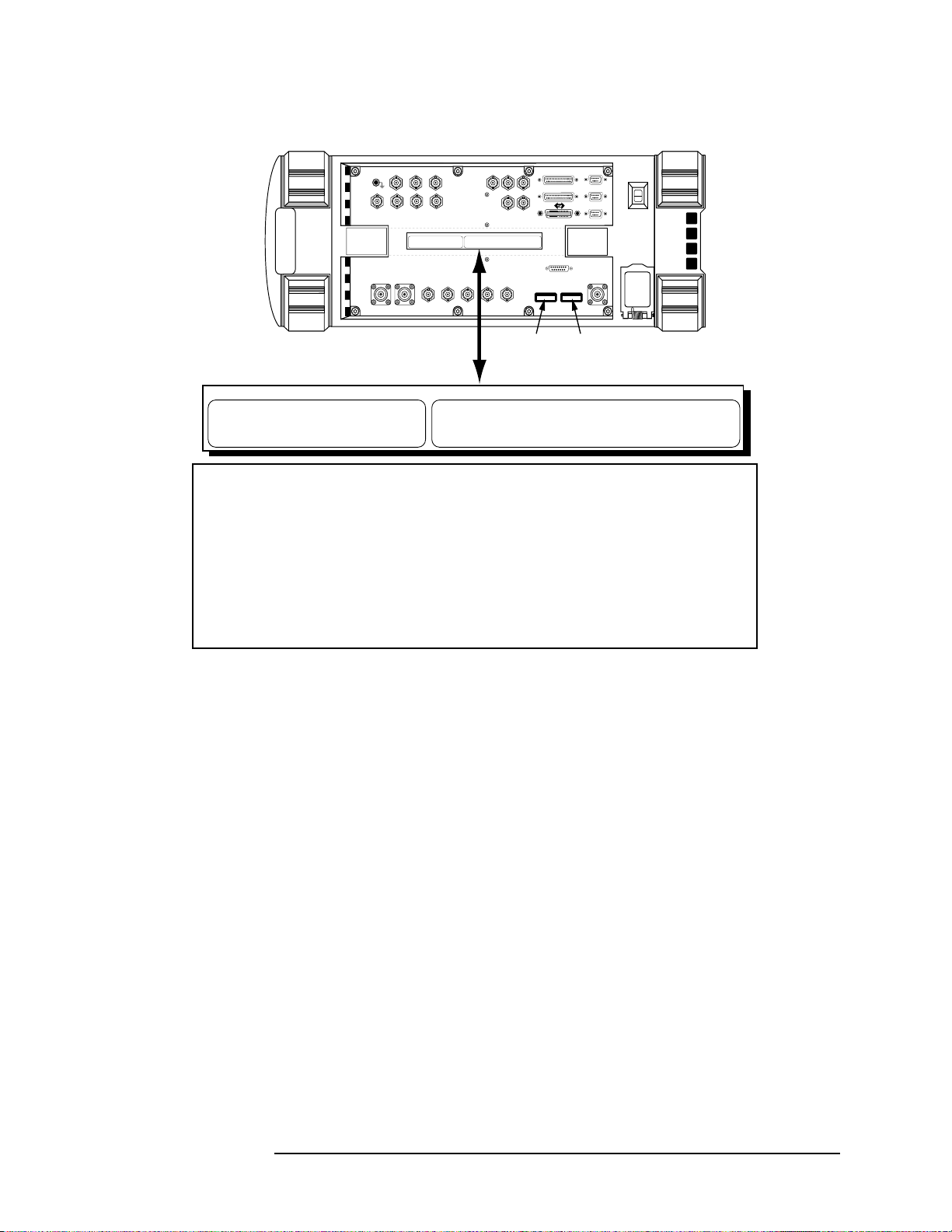
Figure 1 Rubidium Transportation Labels
General Information
Safety Considerations
TRANSPORTATION LABEL
AUDIO OUT
AUDIO IN
HI
AUDIO
VIDEO
EXT SCOPE
MONITOR
OUTPUT
ANT IN DUPLEX OUT
MODULATION
OUT
TRIG IN
INPUT
HEWLETT-PACKARD CO. SPOKANE 24001 E. MISSION AVE. LIBERITY LAKE, WA. 99019
FOR U.S.A. GROUND TRANSPORTATION:
THIS PACKAGE CONFORMS TO THE CONDITIONS AND LIMITATIONS SPECIFIED IN 49CFR 173.424 FOR "RADIOACTIVE
MATERIAL, EXCEPTED PACKAGE - INSTRUMENTS, UN 2910"
8935 TDMA
DIGITAL
MUX OUT
LO
FOR U.S.A. AND INTERNATIONAL AIR TRANSPORTATION:
THIS INSTRUMENT MUST BE SHIPPING AS CARGO WITH THE FOLLOWING ENDORSEMENT IN THE NATURE AND QUANTITY OF GOODS BOX ON THE AIR WAYBILL "RADIOACTIVE MATERIAL, EXCEPTED PACKAGE-INSTRUMENTS"
FRAME
TDMA
CLK OUT
REF IN
REF OUT
TDMA ANALYZER INPUTS
DATA CLOCK
TRIGGER
OPTIONAL
GENERATOR
CDPD
DATA IN
MOD OUT
10 MHz
SYNTH
REF IN
Serial Number
Label
SERIAL 9
PARALLEL 15
SERIAL 10
PARALLEL 16
SERIAL 11
TDMA OUTPUTS
RF IN/OUT
Option Label
003 = CDPD Option
AY5 = Rubidium Option
HEWLETT-PACKARD CO. SPOKANE 24001 E. MISSION AVE. LIBERTY LAKE, WA. 99019
FOR U.S.A. GROUND TRANSPORTATION:
THIS PA CKAGE CONFORMS TO THE CONDITIONS AND LIMITATIONS SPECIFIED IN 49CFR 173.424 FOR "RADIOACTIVE
MATERIAL, EXCEPTED PACKAGE - INSTRUMENTS, UN 2910"
FOR U.S.A. AND INTERNATIONAL AIR TRANSPORTATION:
THIS INSTRUMENT MUST BE SHIPPING AS CARGO WITH THE FOLLOWING ENDORSEMENT IN THE NATURE AND QUANTITY OF GOODS BOX ON THE AIR WAYBILL "RADIOACTIVE MATERIAL, EXCEPTED PACKAGE-INSTRUMENTS"
WARNING
The optional Rubidium Reference assembly (OPTION AY5) contains the radioactive
isotope Rubidium 87. For Test Sets with this option, there are strict transportation
requirements. See transportation label on Test Set. Fines and penalties can results if the
directions on the label are not followed.
If the Test Set is upgraded with this option, you must place the transportation label on
the Test Set. Failure to do so can result in fines and penalties.
If the rubidium assembly is permanently removed from the Test Set, the transportation
label must also be removed. Failure to remove the label when the rubidium assembly is
removed can also result in fines and penalties.
labels.eps
Lifting and Handling
When lifting and handling the Agilent 8935 TDMA Cellular/PCS Base
Station Test Set use ergonomically correct procedu res. Lift and c arry by
the strap on the side panel.
When moving the Test Set more than a few feet, be sure to replace the
front screen cover.
Consumables
Two AA alkalyne batteries are supplied with the Test Set and must be
replaced periodically. When replacing batteries always dispose of old
batteries in a conscientious manner, following manufacturer’s
instructions.
Chapter 1 27
Page 28

General Information
Product Markings
Product Markings
The CE mark shows that the product complies with all relevant
European legal Directives (if accompanied by a year, it signifies when
the design was proven).
The CSA mark is a registered trademark of the Canadian Standards
Association.
28 Chapter 1
C:\Spk\6381\E6381A_SyntaxGuide\book\Preface.fm
Page 29

General Information
Certification
Certification
Agilent Technologies certifies that this product met its published
specifications at the time of shipment from the factory. Agilent further
certifies that its calibration measurements are traceable to the United
States National Institute of Standards and Technology, to the extent
allowed by the Institute’s calibration facility, and to the calibration
facilities of other International Standards Organization members.
.
Chapter 1 29
Page 30

General Information
Certification
DECLARATION OF CONFORMITY
According to ISO/IEC Guide 22 and CEN/CENELEC EN45014
Manufacturer’s Name: Agilent Technologies UK Limited
Manufacturer’s Address:
Electronic Products Solutions Group - Queensferry
South Queensferry
West Lothian, EH30 9TG
Scotland, United Kingdom
Declares that the product
Product Name
:
Model Number:
Product Options:
TDMA PCS Base Station Test Set
E6381A
This declaration covers all options of the above product as
detailed in TCF A-5951-9852-02.
EMC:
Conforms with the protection requirements of European Council Directive 89/336/EEC on the
approximation of the laws of the m ember states relating to electromagnetic compatibility,
against EMC test specifications EN 55011:1991 (Group 1, Class A) and EN 50082-1:1992.
As Detailed in: Electromagne tic Compatibili ty (EMC)
Technical Construction File (TCF) No. A-5951-9852-02.
Assessed by: DTI Appointed Competent Body
Technical Report Number:6893/2201/CBR, dated 23 September 1997
EMC Test Centre,
GEC-Marconi Avionics Ltd.,
Maxwell Building,
Donibristle Industrial Park,
Hillend,
Dunfermline
KY11 9LB
Scotland, United Kingdom
Safety:
The product conforms to the following safety standards:
IEC 61010-1(1990) +A1(1992) +A2(1995) / EN 61010-1:1993
IEC 60825-1(1993) / EN 60825-1:1994
Canada / CSA-C22.2 No. 1010.1-93
The product herewith complies with the requirements of the Low Voltage Directive 73/23 / EEC,
and carries the CE mark accordingly
South Queensferry, Scotland.
For further information, please contact your local Agilent Technologies sales office, agent, or distributor.
st
1
November 2000
R.M. Evans / Manufacturing
Engineering Manager
30 Chapter 1
C:\Spk\6381\E6381A_SyntaxGuide\book\Preface.fm
Page 31

Agilent Technologies Warranty Statement for Commercial Products
Agilent Technologies Wa rranty Statement for
Commercial Products
E6381A TDMA/Cellular PCS Base Station Test Set
General Information
Duration of
Warranty: 1 Year
1. Agilent warrants Agilent hardware, accessor ies and supplies against
defects in materials and work manship fo r the period spec ified above .
If Agilent receives notice of such defects during the warran ty period,
Agilent will, at its option, either repair or replace products which
prove to be defective. Replacement products may be either new or
like-new.
2. Agilent warrants that Agilent software will not fail to execute its
programming instructions, for the period specified above, due to
defects in material and workmanship when properly installed and
used. If Agilent receives notice of such defects during the warranty
period, Agilent will replace software media which does not execute
its programming instructions due to such defects.
3. Agilent does not warrant that the operation of Agilent products will
be uninterrupted or error free. If Agilent is unable, wit hin a
reasonable time, to repair or replace any product to a condition as
warranted, customer will be entitled to a refund of the purchase
price upon prompt return of the product.
4. Agilent products may contain remanufactured part s equivalent to
new in performance or may have been subject to incidental use.
5. The warranty period begins on the date of delivery or on the date of
installation if installed by Agilent. If customer schedules or delays
Agilent installation more than 30 days after delivery, warranty
begins on the 31st day from delivery.
6. Warranty does not apply to defects resulting from (a) improper or
inadequate maintenance or calibration, (b) software, interfacing,
parts or supplies not supplied by Agilent, (c) unauthor ized
modification or misuse, (d) operation outside of the published
environmental specifications for the product, or (e) improper site
preparation or maintenance.
Chapter 1 31
Page 32

General Information
Agilent Technologies Warranty Statement for Commercial Products
7. TO THE EXTENT ALLOWED BY LOCAL LAW, THE ABOVE
WARRANTIES ARE EXCLUSIVE AND NO OTHER
WARRANTYOR CONDITION, WHETHER WRITTEN OR ORAL IS
EXPRESSED OR IMPLIED AND Agilent SPECIFICALLY
DISCLAIMS ANY IMPLIED WARRANTIES OR CONDITIONS OR
MERCHANTABILITY, SATISFACTORY QUALITY, AND FITNESS
FOR A PARTICULAR PURPOSE.
8. Agilent will be liable for damage to tangibl e property per incident up
to the greater of $300,000 or the actual amount paid for the product
that is the subject of the claim, and for damages for bodily injury or
death, to the extent that all su ch damages are d etermined by a cour t
of competent jurisdiction to have been directly caused by a defective
Agilent product.
9. TO THE EXTENT ALLOWED BY LOCAL LAW, THE REMEDIES
IN THIS WARRANTY STATEMENT ARE CUSTOMER’S SOLE
AND EXCLUSIVE REMEDIES. EXCEPT AS INDICATED ABOVE,
IN NO EVENT WILL Agilent OR ITS SUPPLIERS BE LIABLE
FOR LOSS OF DATA OR FOR DIRECT, SPECIAL, INCIDENTAL,
CONSEQUENTIAL (INCLUDING LOST PROFIT OR DATA), OR
OTHER DAMAGE, WHETHER BASED IN CONTRACT, TORT, OR
OTHERWISE.
FOR CONSUMER TRANSACTIONS IN AUSTRALIA AND NEW
ZEALAND: THE WARRANTY TERMS CONTAINED IN THIS
STATEMENT, EXCEPT TO THE EXTENT LAWFULLY
PERMITTED, DO NOT EXCLUDE RESTRICT OR MODIFY AND
ARE IN ADDITION TO THE MANDATORY STATUTOR Y RIGHTS
APPLICABLE TO THE SALE OF THIS PRODUCT TO YOU.
32 Chapter 1
C:\Spk\6381\E6381A_SyntaxGuide\book\Preface.fm
Page 33

Assistance
Product maintenance agreements and other customer assistance
agreements are available for Agilent Technologies products. For any
assistance, contact your nearest Agilent Technologies Sales and Service
Office.
Table 1-2 Regional Sales and Service Office s
General Information
Assistance
United States of Amer ica:
Agilent Technologies
Test and Measurement Call
Center
P.O. Box 4026
Englewood, CO 80155-4026
(tel) 1 800 452 4844
Japan:
Agilent Technologies Japan
Ltd.
Measurement Assistance
Center
9-1 Takakura-Cho,
Hachioji-Shi,
Tokyo 192-8510 , Ja pa n
(tel) (81) 456-56-7832
(fax) (81) 426-56-7840
Asia Pacific:
Agilent Technologies
24/F, Cityplaza One,
111 Kings Road,
Taikoo Shing, Hong Kong
Canada:
Agilent Technologies Canada
Inc.
5150 Spectrum Way
Mississauga, Ont ar io
L4W 5G1
(tel) 1 877 894 4414
Latin America:
Agilent Technologies
Latin America Region
Headquarters
5200 Blue Lagoon Drive,
Suite #950
Miami, Florida 33126
U.S. A.
(tel) (305) 267 4245
(fax) (305) 267 4286
Europe:
Agilent Technologies
European Marketing
Organization
P.O. Box 999
1180 AZ Amstelveen
The Netherlands
(tel) (3120) 547 9999
Australia/New Zealand:
Agilent Technologies
Australia Pty Ltd.
347 Burwood Highway
Forest Hill, Victoria 3131
(tel) 1 800 629 485
(Australia)
(fax) (61 3) 9272 0749
(tel) 0 800 738 378
(New Zealand)
(fax) (64 4) 802 6881
(tel) (852) 3197 7777
(fax) (852) 2506 923 3
Chapter 1 33
Page 34

General Information
Assistance
ATTENTION
Static Sen sitive
Devices
This instrument was constructed in an ESD (electro- static discharge) protected
environment. This is because mos t of the semiconductor devices used in this
instrument are susceptible to damage by static discharge.
Depending on the magnitude of the charge, device substrates can be punctured
or destroyed by contact or mere proximity of a static charge. The result can
cause degradation of device performance, early failure, or immediate
destruction.
These charges are generated in numerous ways such as simple contact,
separation of materials, and normal motions of persons working with static
sensitive devices.
When handling or servicing equipment containing static sensitive devices,
adequate precautions must be taken to prevent device damage or destruction.
Only those who are thoroughly familiar with industry accepted techniques for
handling static sensitive devices should attempt to service circuitry with these
devices.
34 Chapter 1
C:\Spk\6381\E6381A_SyntaxGuide\book\Preface.fm
Page 35

General Information
Documentation
Documentation
Conventions Used in This Manual
The following conventions are used throughout this manual to help
clarify inst ructions and reduce unnecessary text:
•
Test Set
refers to the Agilent Technologies 8935 Series E6381A
TDMA Base Station Test Set.
• Test Set keys are indicated like this:
Preset
• Test Set screen information, such as a measurement result or an
error message, is shown like this: TX Power 7.21 W
Which Document is Required?
The follow i n g documents are pa rt of the Test Set’s document set. Use
the table to help you decide which document you need.
Table 1-3 Document Navigation
Document Part Number Usage
AMPS Application Guide E6381-90017 Use this manual for making AMPS bas e
station measureme nt s.
Programmer’s Guide E6380-90018 Use this manual to learn how to program the
Test Set.
GPIB Syntax Guide E6381-90014 Use this listing of GP IB syntax when writing
control programs for the Test Set.
Assembly Level Repair Guide E6381-90015 Use this manual to perform calibration on the
Test Set and for general service information.
Reference Guide E6381-90019 Use this manual for general information on
accessing and changing settings, general Test
Set operation, connector descriptions, and
error messages. It also contains information
on loading and running the various
automated test rout in e s (RF Tools) built in to
the Test Set.
HELP Screens (integral to
Test Set)
CD-ROM E6381-90020 All user documentation
Chapter 1 35
Pressing the
a variety of Test Set operations and tests.
key accesses information on
Help
Page 36

General Information
Trademark Acknowledgements
Trademark Acknowledgement s
Hewlett-Packard and HP are registered trademarks of
Hewlett-Packard Company.
Microsoft‚ Windows, and MS-DOS‚ are registered trademarks of
Microsof t C orporatio n.
ProComm‚ is a registered trademark of D a taStorm Technologies, Inc.
HyperTerminal is a registered trademark of Hilgraeve, Incorporated.
Pentium is a registered trademark of Intel Corporation.
36 Chapter 1
C:\Spk\6381\E6381A_SyntaxGuide\book\Preface.fm
Page 37

2
GPIB Command Dictionary
This is the GPIB command dictionary. It contains syntax and guidelines
for the GPIB commands available in the Test Set.
If you know the name of the control fi eld on the s cre en that you want t o
control programmatically, look that field’s name up in the index of this
guide. The index will guide you to the command that controls that field.
37
Page 38

GPIB Command Dictionary
Notice
Notice
Permission to use, copy, and distribute this template is hereby granted,
provided that the above copyright notice appears in all copies and that
both that copyright notice and this permission notice appear in
supporting hardcopy and online documentation. All other rights
reserved.
The name Agilent Technologies or the Agilent Technologies logo may
not be used in advertising or publicity pertaining to distribution of this
template without specific, written prior permission. Agilent
Technologies makes no representations about the suitability of this
template for any purpose. It is provided “as is” without expressed or
implied warranty.
Agilent Technologies disclaims all warranties with regard to this
template, including all implied warranties of merchantability and
fitness. In no event shall Agilent Technologies be liable for any special,
indirect or consequential damages or any damages whatsoever
resulting from loss of use, data or profits, whether in an action of
contract, negligence or other tortious action, arising out of or in
connection with the use or performance of this template.
38 Chapter 2
Page 39

GPIB Command Dictionary
Using This Dictionary
Using This Dictionary
This dictionary is arranged according to GPIB subsystem. Each
subsystem contains syntax for a specific s et of functions within the Test
Set.
When using the electronic form of this guide, you can cut- and-pas te the
syntax into your programming code. It is set up especially for this
purpose, and where possible, the syntax includes the limits or expected
values for the command.
Description of Commands
The typical format of each entry is as follows:
root:branch1:branch2:branch3:command parameter !limits
root:branch1:branch2:branch3:command ‘argument’
Equivalent Commands
Commands separated by a vertical bar | are equivalent. For example,
for the command AFG2|ENCoder:AMPS:BUSY ‘Idle’, either
AFG2:AMPS:BUSY ‘Idle’
or
ENC:AMPS:BUSY ‘Idle’
will set the AMPS encoder to the idle state.
Optional Commands
Commands enc l osed in square b rackets [ ] are optional. For exampl e,
for the command AFG2|ENC:NAMP|NTAC[:FOCC]:AM 30 either
AFG2:NAMP:FOCC:AM 30
or
AFG2:NAMP:AM 30
will set the NAMPS encoder’s data level on t he f orward cont rol channel
to AM. (Other combinations are possible with the above command.)
Chapter 2 39
Page 40

:AIN <string> :AIN?
GPIB Command Dictionary
AFANalyzer subsystem
AFANalyzer subsystem
These commands set/query the input state of the AUDIO IN LO
connector.
Syntax
AFAN:AIN ‘Gnd’
‘Float’
‘600 to Hi’
AFAN:AIN?
Screen/field equivalent
AFAN:AIN sets the Audio In Lo field on the AF ANALYZER screen.
:DEMPhasis <string> :DEMPhasis?
These commands set/query the state of the de-emphasis networks in
the audio analyzer and speaker circuitry.
Syntax
AFAN:DEMP ‘750 us’
‘Off’
AFAN:DEMP?
Screen/field equivalent
AFAN:DEMP sets the De-Emphasis field on the AF ANALYZER screen.
40 Chapter 2
Page 41

:DEMPhasis:GAIN <string> :DEMPhasis:GAIN?
These commands set/query the AF analyzer’s amplifier gain. This
command is only effective when autoranging is turned off using the
AFAN:RANG ‘Hold’ command.
Gain is automatically set when the AFAN:RANG ‘Auto’ command is
used. If autoranging is enabled (AFAN:RANG ‘Auto’) and you attempt
to change the gain setting by sending the AFAN:DEMP:GAIN
command, the value you send will be overridden by the autoranging
function.
Syntax
AFAN:DEMP:GAIN ‘0 dB’
‘10 dB’
‘20 dB’
‘30 dB’
GPIB Command Dictionary
AFANalyzer subsystem
AFAN:DEMP:GAIN?
Screen/field equivalent
AFAN:DEMP:GAIN sets the De-Emp Gain field on the AF ANALYZER
screen when the Gain Cntl field is set to Hold.
Chapter 2 41
Page 42

GPIB Command Dictionary
AFANalyzer subsystem
:DETector <string> :DETector?
These commands set/query the type of detector used for AF signals.
Syntax
AFAN:DET ‘RMS’
'RMS*SQRT2'
'PK+'
'PK-'
'PK+-/2'
'PK+-MAX'
'PK+ HOLD'
'PK- HOLD'
'PK+-/2 Hd'
'PK+-MX Hd'
AFAN:DET?
Screen/field equivalent
AFAN:DET controls the Detector field on the AF ANALYZER screen.
:DETector:PKLocation <string> :DETector:PKLocation?
These commands set/query the signal source for the peak detector
measurements.
Syntax
AFAN:DET:PKL ‘Filters’
‘De-Emp’
AFAN:DET:PKL?
Screen/field equivalent
AFAN:DET:PKL contro ls the Pk Det To field on the AF ANALYZER
screen.
42 Chapter 2
Page 43

:DETector:SETTling <string> :DETector:SETTling?
These commands set/query the settling time for audio measurements.
(Use Fast when measuring signals greater than 200 Hz).
Syntax
AFAN:DET:SETT ‘Fast’
‘Slow’
AFAN:DET:SETT?
Screen/field equivalent
AFAN:DET SETT controls the Settling field on the AF ANALYZER
screen.
:ELResistor <real number> :ELResistor?
GPIB Command Dictionary
AFANalyzer subsystem
These commands set/query the external load resistance for
measurements using the AUDIO IN HI and LO connectors.
This command utilizes the “Real Number Setting Syntax” on page 208,
but does not use the :STATe command.
Syntax
AFAN:ELR <real number> !valid from 1 ohm to 1 megohm
AFAN:ELR !returns the value in ohms
Screen/field equivalent
AF AN:ELR controls the Ext Load R field on the AF ANALYZER screen.
Chapter 2 43
Page 44

GPIB Command Dictionary
AFANalyzer subsystem
:FILT1|FILTER1 <string> :FILT1?|FILTER1?
These commands set/query the audio filter 1 selection.
Syntax
AFAN:FILT1 ‘<20Hz HPF’
'50HZ HPF'
'300Hz HPF'
'C MESSAGE'
AFAN:FILT1?
Screen/field equivalent
AFAN:FILT1 controls the Filter 1 field on the AF ANALYZER screen
:FILT2|FILTER2 <string> :FILT2?|FILTER2?
These commands set/query the audio filter 2 selection.
Syntax
AFAN:FILT2 ‘300Hz LPF’
‘3kHz LPF’
‘15kHz LPF’
‘>99kHz LP’
‘6kHz BPF’
AFAN:FILT2?
Screen/field equivalent
AFAN:FILT2 controls the Filter 2 field on the AF ANALYZER screen.
44 Chapter 2
Page 45

:GTIMe <real number> :GTIMe?
This command sets the gate time (how long the AF counter s amples the
input signal) for the audio frequency counter.
This command utilizes the “Real Number Setting Syntax” on page 208,
but does not use the :STATe command.
Syntax
AFAN:GTIM <real number> !valid from 10 milliseconds to 1
second
AFAN:GTIM?
Screen/field equivalent
AFAN:GTIM controls the AF C n t Gate field on the AF ANALYZER
screen.
GPIB Command Dictionary
AFANalyzer subsystem
:INPut <string> :INPut?
These commands set/query the input to the audio analyzer.
Syntax
AFAN:INP ‘FM Demod’
‘SSB Demod’
‘Ext Mod’
‘AM Mod’
AFAN:INP?
Screen/field equivalent
AFAN:INP controls the AF Anl In field on the AF ANALYZER screen.
‘AM Demod’
‘Audio In’
‘FM Mod’
‘Audio Out’
Chapter 2 45
Page 46

GPIB Command Dictionary
AFANalyzer subsystem
:INPut:GAIN <string> :INPut:GAIN?
These commands set/query the input gain setting for the audio
analyzer. This command is only effective when autoranging is turned
off using the AFAN:RANG ‘Hold’ command.
Gain is automatically set when the AFAN:RANG ‘Auto’ command is
used. If autoranging is enabled (AFAN:RANG ‘Auto’) and you attempt
to change the gain setting by sending the AFAN:INP:GAIN command,
the value you send will be overridden by the autoranging function.
Syntax
AFAN:INP:GAIN ‘0 dB’
‘20 dB’
‘40 dB’
AFAN:INP:GAIN
Screen/field equivalent
AFAN:INP:GAIN controls the Input Gain field on the AF ANALYZER
screen when the Gain Cntl field is set to Hold.
46 Chapter 2
Page 47

:NOTCh:GAIN <string> :NOTCh:GAIN?
These commands set/query the gain of the AF analyzer’s notch filter
amplifier. This command is only effective when autoranging is turned
off using the AFAN:RANG ‘Hold’ command.
Gain is automatically set when the AFAN:RANG ‘Auto’ command is
used. If autoranging is enabled (AFAN:RANG ‘Auto’) and you attempt
to change the gain setting by sending the AFAN:NOTC:GAIN
command, the value you send will be overridden by the autoranging
function.
Syntax
AFAN:NOTC:GAIN ‘0 dB’
‘10 dB’
‘20 dB’
‘30 dB’
GPIB Command Dictionary
AFANalyzer subsystem
‘40 dB’
AFAN:NOTC:GAIN?
Screen/field equivalent
AFAN:NOTC:GAIN controls the Notch Gain field on the AF
ANALYZER screen when the Gain Cntl field is set to Hold.
:NOTCh:FREQuency <real number> :NOTCh:FREQuency?
These commands set/query the center frequency for the variable
frequency notch filter. This command utilizes the “ Real Number Setting
Syntax” on page 208, but does not use the :STATe command.
Syntax
AFAN:NOTC:FREQ <real number> !valid 330 Hz to 10 kHz
AFAN:NOTC:FREQ?
Screen/field equivalent
AFAN:NOTC:FREQ controls the Notch Freq field on the AF
ANALYZER screen.
Chapter 2 47
Page 48

GPIB Command Dictionary
AFANalyzer subsystem
:RANGing <string> :RANGing?
These commands set/query the gain control mode of the AF analyzer.
Syntax
AFAN:RANG ‘Auto’
‘Hold’
AFAN:RANG?
Screen/field equivalent
AFAN:RANG controls the Gain Cntl field on the AF ANALYZER
screen.
:SMPoint <string> :SMPoint?
These commands set/query the signal source for the oscilloscope.
Syntax
AFAN:SMP ‘De-Emp’
‘Filters’
‘Input’
‘Notch’
AFAN:SMP?
Screen/field equivalent
AFAN:SMP controls the Scope To field on the AF ANALYZER screen.
:SPEaker:MODE <string> :SPEaker:MODE?
These commands set/query the automatic level control (ALC) function
for the instrument’s internal speaker.
Syntax
AFAN:SPE:MODE ‘On’
‘Off’
AFAN:SPE:MODE?
Screen/field equivalent
AFAN:SPE:MODE controls the Speaker ALC field on the AF
ANALYZER screen.
48 Chapter 2
Page 49

:SPEaker:VOLume <string> :SPEaker:VOLume?
These commands set/query the speaker volume, which is controlled by
the Volume knob when ‘Pot’ is selected.
Syntax
AFAN:SPE:VOL ‘Pot’
‘Off’
AFAN:SPE:VOL
Screen/field equivalent
AFAN:SPE:VOL controls the Speaker Vol field on the AF ANALYZER
screen.
GPIB Command Dictionary
AFANalyzer subsystem
Chapter 2 49
Page 50

GPIB Command Dictionary
AFG1|AFGENERATOR1 subsystem
AFG1|AFGENERATOR1 subsystem
:AM <real number> :AM?
This command sets AM modulation depth when the AFG1:DEST ‘AM’
is used first.
This command utilizes the “Real Number Setting Syntax” on page 208.
Syntax
AFG1:AM <real number>
AFG1:AM? !returns the value of the amplitude modulation
Screen/field equivalent
AFG1:AM controls the AFGen1 To field (lower subfield) on the RF
GENERATOR screen.
:DESTination <string> :DESTination?
AFG1:DEST sets/queries the destination of AF generator 1’s signal.
Syntax
AFG1:DEST ‘AM’
‘FM’
‘Audio Out’
AFG1:DEST?
Screen/field equivalent
AFG1:DEST controls the AFGen1 To field (upper subfield) on the RF
GENERATOR screen.
50 Chapter 2
Page 51

:FM <real number> :FM?
This comman d se ts FM modulation deviati on when the AFG1:DES T
‘FM’ command is used.
This command utilizes the “Real Number Setting Syntax” on page 208.
Syntax
AFG1:FM <real number>
AFG1:FM?
Screen/field equivalent
AFG1:FM controls the AFGen1 To field (lower subfield) on the RF
GENERATOR screen.
:FREQuency <real number> :FREQuency?
GPIB Command Dictionary
AFG1|AFGENERATOR1 subsystem
This command set the frequency of audio frequency generator 1.
This command utilizes the “Real Number Setting Syntax” on page 208,
not includi ng the :STATe command.
Syntax
AFG1:FREQ <real number>
AFG1:FREQ
Screen/field equivalent
AFG1:FREQ controls the AFGen1 Freq field on the RF GENERATOR
screen.
Chapter 2 51
Page 52

GPIB Command Dictionary
AFG1|AFGENERATOR1 subsystem
:OUTPut <real number> :OUTPut?
This command sets the amplitude of the audio signal (volts rms) at the
AUDIO OUT connector if the AFG1:DEST is ‘Audio Out’.
This command utilizes the “Real Number Setting Syntax” on page 208
Syntax
AFG1:OUTP <real number>
AFG1:OUTP?
Screen/field equivalent
AFG1:OUTP controls the AFGen1 To field (lower subfield) on the RF
GENERATOR screen.
52 Chapter 2
Page 53

AFG2|ENCoder subsystem
:AM <real number> :AM?
This command sets AM mo dulation depth if the command AFG2:DEST
‘AM’ is used first.
This command utilizes the “Real Number Setting Syntax” on page 208.
Syntax
AFG2:AM <real number>
AFG2:AM? !returns the value of the amplitude modulation
Screen/field equivalent
GPIB Command Dictionary
AFG2|ENCoder subsystem
AFG2:AM controls the AFGen2 To field (lower subfield) on the RF
GENERATOR screen when the upper subfield is set to AM.
:BURSt <integer> :BURSt?
These commands set/query the number of times the message data is
output. To use this function , t he A FG2:SEND:MODE command must
specify ‘Burst’ first.
This command uses only the :INCR command of the “Integer Number
Setting Syntax” on page 162.
Syntax
AFG2:BURS <integer>
AFG2:BURS?
Screen/field equivalent
AFG2:BURS co n t rols the Bursts field on the SIGNALING ENCODER
screen when the Mode field is set to DTMF, AMPS-TACS, or NAMP-NTAC.
Chapter 2 53
Page 54

GPIB Command Dictionary
AFG2|ENCoder subsystem
:DESTination <string> :DESTination?
:DEST sets/queries the destination of the AF generator 2’s signal.
Syntax
AFG2:DEST ‘AM’
‘FM’
‘Audio Out’
AFG2:DEST?
Screen/field equivalent
AFG2:DEST controls the AFGen2 To field (upper subfield) on the RF
GENERATOR screen.
54 Chapter 2
Page 55

:FILTer <string> :FILTer?
To improve performance, one of four premodulation filters is
automatically selected for each encoder mode. The automatically
selected filter can be changed only by using GPIB commands.
We recommend that you leave this setting at its automatically selected
setting.
If it is necessary to override the automatic settings, the
AFG2:FILT:MODE ‘ON’ command mu st be executed fi rst (filter mode
OFF is the power up default state). The following error will occur if the
user attempts to select an alter nate fil ter without firs t sett ing t he f ilter
mode to ON: Entry not accepted. The syntax to change or query the
premodulation filter is shown in the example below.
Syntax
AFG2:FILT ‘None’
GPIB Command Dictionary
AFG2|ENCoder subsystem
‘20 kHzLPF’
‘250 HzLPF’
‘150 HzLPF’
AFG2:FILT?
Example
AFG2:FILT:MODE 'ON' !turn filter selection mode on
AFG2:FILT:MODE? !query the current mode setting
AFG2:FILT 'NONE|20kHz LPF|250Hz LPF|150Hz LPF'
!select one to change the setting
AFG2:FILT? !query the new filter setting
Screen/field equivalent
AFG2:FILT has no screen/field equivalent.
Chapter 2 55
Page 56

GPIB Command Dictionary
AFG2|ENCoder subsystem
:FILTer:MODE <string> :FILTer:MODE?
These commands set/query the premodulation filter’s control.
We recommend that you leav e thi s sett ing at its def aul t setting (filter
mode OFF is the power up default state). See the :FILTer command on
page 55 for more information about the premodulation filters.
Syntax
AFG2:FILT:MODE ‘ON’
‘OFF’
AFG2:FILT:MODE?
Screen/field equivalent
AFG2:FILT:MODE has no screen/field equivalent.
:FM <real number> :FM?
This command sets FM modulation deviation if the AFG2: DEST is ‘FM’.
This command utilizes the “Real Number Setting Syntax” on page 208.
Syntax
AFG2:FM <real number>
AFG2:FM?
Screen/field equivalent
AFG2:FM controls the AFGen2 To field (lower subfield) on the RF
GENERATOR screen when the upper subfield is set to FM.
56 Chapter 2
Page 57

:FREQuency <real number> :FREQuency?
This command set/queries the output frequency of AF generator 2.
This command utilizes the “Real Number Setting Syntax” on page 208,
but does not use the :STATe command.
Syntax
AFG2:FREQ <real number>
AFG2:FREQ
Screen/field equivalent
AFG2:FREQ controls the AFGen2 Freq field on the RF GENERATOR
screen.
:MODE <string>
GPIB Command Dictionary
AFG2|ENCoder subsystem
This command sets the type of signaling encoder.
Syntax
AFG2:MODE ‘Func Gen’
‘DTMF’
‘AMPS-TACS’
‘NAMP-NTAC’
AFG2:MODE?
Screen/field equivalent
AFG2:MODE controls the Mode field on the SIGNALING ENCODER
screen.
Chapter 2 57
Page 58

GPIB Command Dictionary
AFG2|ENCoder subsystem
:OUTPut <real number> :OUTPut?
This command sets the amplitude of the audio signal (volts rms) at the
AUDIO OUT connector if the AFG2:DEST is ‘Audio Out’.
This command utilizes the “Real Number Setting Syntax” on page 208.
Syntax
AFG2:OUTP <real number>
AFG2:OUTP?
Screen/field equivalent
AFG2:OUT controls the AFGen2 To field (lower subfield) on the RF
GENERATOR screen when the upper subfield is set to Audio Out.
:PEMPhasis <string> :PEMPhasis?
This command sets pre-emphasis filters for the DTMF encoder.
Syntax
AFG2:PEMP ‘On’
‘Off’
AFG2:PEMP?
Screen/field equivalent
AFG2:PEMP controls the Pre-Emp field on the SIGNALING ENCODER
screen when the Mode field is set to DTMF.
58 Chapter 2
Page 59

:POLarity <string> :POLarity?
This command causes the digitally modulated signals to be sent with a
normal or inverted response to the digital data. When Inverted, a
digital 1 produces a frequency shi ft in an FM carrier opposite to normal
operation.
Syntax
AFG2:POL ‘Norm’
‘Invert’
AFG2:POL?
Screen/field equivalent
AFG2:POL controls the Polarity field on the SIGNALING ENCODER
screen when the Mode field is set to AMPS-TACS or NAMP-NTAC.
GPIB Command Dictionary
AFG2|ENCoder subsystem
:SEND:MODE <string> :SEND:MODE?
These commands set/query the mode used when a message is sent.
• ‘Single’ outputs the entire message once.
• ‘Burst’ outputs the message the number of times specified by the
AFG2:BURS command.
• ‘Cont’ outputs the message continuously until the AFG2:STOP
command is sent.
• ‘Step’ outputs a single step in an encoder sequence each time the
AFG2:SEN D com mand is sent. A fter the enti re sequence is output,
the encoder returns to the first character in the sequence.
Syntax
AFG2:SEND:MODE ‘Single’
‘Burst’
‘Cont’
‘Step’
AFG2:SEND:MODE?
Screen/field equivalent
AFG2:SEND:MODE controls then Send Mode field on the SIGNALING
ENCODER screen when the Mode field is set to AMPS-TACS, NAMP-NTAC,
or DTMF.
Chapter 2 59
Page 60

:SEND
:STOP
GPIB Command Dictionary
AFG2|ENCoder subsystem
This command sends the encoder data stream’.
Syntax
AFG2:SEND
Screen/field equivalent
AFG2:SEND controls the Send field on the SIGNALING ENCODER
screen when the Mode field is set to AMPS-TACS, NAMP-NTAC, or DTMF.
This command stops the data stream that is being output when
AFG2:SEND:MODE is ‘Cont’ or ‘Burst’.
Syntax
AFG2:STOP
Screen/field equivalent
AFG2:STOP controls the Stop field on the SIGNALING ENCODER
screen when the Mode field is set to AMPS-TACS, NAMP-NTAC, or DTMF.
60 Chapter 2
Page 61

:AMPS|TACS:BUSY <string> :AMPS|TACS:BUSY?
These commands set/query the busy /idle status information included in
the signaling sequ ence.
• ‘Idle’ sets the busy/idle bits of the forward c o ntrol channe l
information to indicate an idle state.
• ‘Busy’ sets the busy/idle bits of the forward control channel
information to indicate an busy state.
• ‘WS Delay’ (word sync delay) prevents a busy/idle change until the
word sync information has been received and a defined number of
delay bits has been counted. The delay is set with the
AFG2:AMPS:BUSY:DEL command.
• ‘1stBitDly’ ( fi rst bit dela y ) causes the bu sy/idle bit to be set after a
bit has been received and a defined number of delay bits has been
counted. The delay is set with the AFG2:AMPS:BUSY:DEL
command.
GPIB Command Dictionary
AFG2|ENCoder subsystem
This command requires that the AFG2:AMPS:CHAN command
specifies ‘Cntl’.
Syntax
AFG2:AMPS:BUSY ‘Idle’
‘Busy’
‘WS Delay
‘1stBitDly’
AFG2:AMPS:BUSY?
Screen/field equivalent
AFG2:AMPS:BUSY controls the Busy/Idle field on the SIGNALING
ENCODER screen when the Mode field is set to AMPS-TACS and the
Channel field is set to Cntl.
Chapter 2 61
Page 62

GPIB Command Dictionary
AFG2|ENCoder subsystem
:AMPS|TACS:BUSY:DELay <integer>
These commands set/query the number of bits that are counted befo re a
busy/idle bit changes fr om the idle state to t he busy st ate. This f unction
is used in conj unction w i th the WS Delay and 1stBitDly settings o f the
AFG2:AMPS|T ACS:BUSY command. This command also require s that
the AFG2:AMPS:CHAN command is specifies ‘Cntl’.
This command utilizes only the :INCR command of the “Integer
Number Setting Syntax” on page 162.
Syntax
AFG2:AMPS:BUSY:DEL <real number>
Screen/field equivalent
AFG2:AMPS:BUSY:DEL controls the B/I Delay field on the
SIGNALING ENCODER screen when the Mode field is set to
AMPS-TACS and the Channel field is set to Cntl .
:AMPS|TACS:CHANnel <string> :AMPS|TACS:CHANnel?
These commands set/query the channel type. ‘Cntl’ selects the forward
control channel (FOCC). ‘Voice’ selects the forward voice channel (FVC).
Syntax
AFG2:AMPS:CHAN ‘Cntl’
‘Voice’
AFG2:AMPS:CHAN?
Screen/field equivalent
AFG2:AMPS:CHAN controls the Channel field on the SIGNALING
ENCODER screen when the Mode field is set to AMPS-TACS.
62 Chapter 2
Page 63

:AMPS|TACS:DATA:AM <real number> :AMPS|TACS:DATA:AM?
These commands set/query the data level when the AFG2:DEST ‘AM’
command is used first. The data level units are %.
This command utilizes the “Real Number Setting Syntax” on page 208.
Syntax
AFG2:AMPS:DATA:AM
AFG2:AMPS:DATA:AM?
Screen/field equivalent
AFG2:AMPS:DA TA:AM controls the Data Level field when AFGen2 To
field is set to AM on the SIGNALING ENCODER screen when the Mode
field is set to AMPS-TACS.
:AMPS|TACS:DATA:FM <real number> :AMPS|TACS:DATA:FM?
GPIB Command Dictionary
AFG2|ENCoder subsystem
These commands set/query the data level when the AFG2:DEST ‘FM’
command is used. The data level units are kHz.
This command utilizes the “Real Number Setting Syntax” on page 208.
Syntax
AFG2:AMPS:DATA:FM
AFG2:AMPS:DATA:FM?
Screen/field equivalent
AFG2:AMPS:DATA:FM controls the Data Level field when AFGen2 To
field is set to FM on the SIGNALING ENCODER screen when the Mode
field is set to AMPS-TACS.
Chapter 2 63
Page 64

GPIB Command Dictionary
AFG2|ENCoder subsystem
:AMPS|TACS:DATA:LEVel <real number> :AMPS|TACS:DATA:LEVel?
These commands set/query the data level when the AFG2:DEST ‘Aud io
Out’ command is used first. The data level units are mV.
This command utilizes the “Real Number Setting Syntax” on page 208.
Syntax
AFG2:AMPS:DATA:LEV
AFG2:AMPS:DATA:LEV?
Screen/field equivalent
AFG2:AMPS:DATA:LEV controls the Data Level field when AFGen2
To field is set to Audio Out on the SIGNALING ENCODER screen
when the Mode field is set to AMPS-TACS.
:AMPS|TACS:DATA:RATE <real number>
These commands set/query the data rate of the encoded message.
This command utilizes the “Real Number Setting Syntax” on page 208
but does not use the :STATe command.
Syntax
AFG2:AMPS:DATA:RATE
Screen/field equivalent
AFG2:AMPS:DATA:RATE controls the Data Rate field on the
SIGNALING ENCODER screen when the Mode field is set to
AMPS-TACS.
64 Chapter 2
Page 65

:AMPS|TACS:FILLer:DATA1 <string>
:AMPS|TACS:FILLer:DATA2 <string>
:AMPS|TACS:FILLer:DATA1?
:AMPS|TACS:FILLer:DATA2?
These commands set/query FOCC filler data. Each filler conta ins 7
hexadecimal characters represe nting the 2 type bits and 26 information
bits of the control filler/message word. The control filler is sent
continuously when the :AMPS|TACS:FILL:SEND command is used or
after a control message has been sent using :AMPS|TACS:SEND.
Both filler fields must be full (seven digits) for the forward control
channel information to be structured correctly. Do not leave any blank
spaces.
To use this command, AFG2:AMPS:CHAN must be set to ‘Cntl’.
Syntax
AFG2:AMPS:FILL:DATA1 <string>
GPIB Command Dictionary
AFG2|ENCoder subsystem
AFG2:AMPS:FILL:DATA2 <string>
AFG2:AMPS:FILL:DATA1?
AFG2:AMPS:FILL:DATA2?
Screen/field equivalent
AFG2:AMPS:FILL:DATA1 and DATA 2 control the Filler fields for
Stream A and Stream B on the SIGNALING ENCODER screen when
the Mode field is set to AMPS-TACS and the Channel field is set to Cntl.
:AMPS|TACS:FILLer:SEND
This command sends the filler information that is entered with the
AFG2:FILL:DATA1 and AFG2:FILL:DATA2 commands.
To use this command, AFG2:AMPS:CHAN must be set to ‘Cntl’.
Syntax
AFG2:AMPS:FILL:SEND
Screen/field equivalent
AFG2:AMPS:FILL:SEND controls the Send Filler field on the
SIGNALING ENCODER screen when the Mode field is set to
AMPS-TACS and the Channel field is set to Cntl.
Chapter 2 65
Page 66

GPIB Command Dictionary
AFG2|ENCoder subsystem
:AMPS|TACS:FILLer:STOP
This command stops the output of filler data.
To use this command, AFG2:AMPS:CHAN must be set to ‘Cntl’.
Syntax
AFG2:AMPS:FILL:STOP
Screen/field equivalent
AFG2:AMPS:FILL:STOP controls the Stop Filler field on the
SIGNALING ENCODER screen when the Mode field is set to
AMPS-TACS and the Channel field is set to Cntl.
:AMPS|TACS:FVCMessage <string> :AMPS|TACS:FVCMessage?
These commands set/query the 7 hexadecimal characters repres enting
the 2 type bits and 26 information bits in the forward voice channel
(FVC) message w o rd. All seven chara ct ers must be pre sent (with no
blank spaces) for the message to be valid. The SAT is turned off while
the FVC message stream is sent.
This command is used with the AFG2:AMPS:CHAN ‘Voice’ command.
Syntax
AFG2:AMPS:FVCM <string>
AFG2:AMPS:FVCM?
Screen/field equivalent
AFG2:AMPS:FVCM controls the Message field on the SIGNALING
ENCODER screen when the Mode field is set to AMPS-TACS and the
Channel field is set to Voice.
66 Chapter 2
Page 67

:AMPS|TACS:MESSage:DATA1 <string>
:AMPS|TACS:MESSage:DATA2 <string>
:AMPS|TACS:MESSage:DATA1?
:AMPS|TACS:MESSage:DATA2?
These commands set/query FOCC Stream A an d Stream B message
data. Like the filler data, the message information can only be input in
full (seven digit) lines. Also, message streams A and B must have the
same number of lines in them.
To use this command, AFG2:AMPS:CHAN must be set to ‘Cntl’.
Syntax
AFG2:AMPS:MESS:DATA1 <string>
AFG2:AMPS:MESS:DATA2 <string>
AFG2:AMPS:MESS:DATA1?
AFG2:AMPS:MESS:DATA2?
GPIB Command Dictionary
AFG2|ENCoder subsystem
Screen/field equivalent
AFG2:AMPS:MESS cont rols the Message fields for FOCC Stream A
and Stream B on the SIGNALING ENCODER screen when the Mode
field is set to AMPS-TACS. These fields are displayed only when the
Channel field is set to Cntl.
:AMPS|TACS:SAT:AM <real number> :AMPS|TACS:SAT:AM?
These commands set/query the SAT level when the AFG2:DEST ‘AM’
and AFG2:AMPS:CHAN ‘Voice’ commands are used. The SAT level
units are %.
This command utilizes the “Real Number Setting Syntax” on page 208.
Syntax
AFG2:AMPS:SAT:AM
Screen/field equivalent
AFG2:AMPS:SAT:AM controls the SAT Level field when AFGen2 To
field is set to AM on the SIGNALING ENCODER screen when the Mode
field is set to AMPS-TACS and the Channel field is set to Voice.
Chapter 2 67
Page 68

GPIB Command Dictionary
AFG2|ENCoder subsystem
:AMPS|TACS:SAT:FM <real number> :AMPS|TACS:SAT:FM?
These commands set/query the SAT level when the AFG2:DEST ‘FM’
and AFG2:AMPS:CHAN ‘Voice’ commands are used. The SAT level’s
units are kHz.
This command utilizes the “Real Number Setting Syntax” on page 208.
Syntax
AFG2:AMPS:SAT:FM
Screen/field equivalent
AFG2:AMPS:SAT:FM controls the SAT Level field when AFGen2 To
field is set to FM on the SIGNALING ENCODER screen when the Mode
field is set to AMPS-TACS and the Channel field is set to Voice.
:AMPS|TACS:SAT:LEVel <real number> :AMPS|TACS:SAT:LEVel
These commands set/query the SAT level when the AFG2:DEST ‘Audio
Out’ and AFG2:AMPS:CHAN ‘Voice’ commands are used. The SAT level
units are mV.
This command utilizes the “Real Number Setting Syntax” on page 208.
Syntax
AFG2:AMPS:SAT:LEV
Screen/field equivalent
AFG2:AMPS:SAT:LEV controls the SAT Level field when AFGen2 To
field is set to Audio Out on the SIGNALING ENCODER screen when
the Mode field is set to AMPS-TACS and the Channel field is set to Voice.
68 Chapter 2
Page 69

:AMPS|TACS:SAT:FREQuency <real number>
These commands set/query the superviso ry audio tone ’ s fr equency. This
signal is sent continuously whenever AFG2:AMPS:CHAN ‘Voice’ is
used, but is interrupted when a FVC message is sent.
This command utilizes the “Real Number Setting Syntax” on page 208
but does not use the :STATe command.
Syntax
AFG2:AMPS:SAT:FREQ
Screen/field equivalent
AFG2:AMPS:SAT:FREQ controls the SAT Freq field on the
SIGNALING ENCODER screen when the Mode field is set to
AMPS-TACS and the Channel field is set to Voice.
:AMPS|TACS:STANdard <string> :AMPS|TACS:STANdard?
GPIB Command Dictionary
AFG2|ENCoder subsystem
These commands set/query the radio standard for the encoder.
Syntax
AFG2:AMPS:STAN ‘AMPS’
‘TACS’
‘JTACS’
AFG2:AMPS:STAN?
Screen/field equivalent
AFG2:AMPS:STAN controls the Standard field on the SIGNALING
ENCODER screen when the Mode field is set to AMPS-TACS.
Chapter 2 69
Page 70

GPIB Command Dictionary
AFG2|ENCoder subsystem
:DTMF:FREQuency:COLumn <multiple real number> :DTMF:FREQuency:COLumn?
These commands set/query the frequencies for the vertical columns in
the symbol frequencies table of the DTMF encoder.
Syntax
AFG2:DTMF:FREQ:COL <integer value>,<real number>
AFG2:DTMF:FREQ:COL? <integer value>
Screen/field equivalent
AFG2:DTMF:FREQ:COL controls vertical columns in the Symbol
Frequencies (Hz): table on the SIGNALING ENCODER screen
when the Mode field is set to DTMF.
:DTMF:FREQuency:ROW <multiple real number> :DTMF:FREQuency:ROW?
These commands set/query the frequenci es f or the horizontal rows in
the symbol frequencies table of the DTMF encoder.
Syntax
AFG2:DTMF:FREQ:ROW <integer value>,<real number>
AFG2:DTMF:FREQ:ROW? <integer value>
Screen/field equivalent
AFG2:DTMF:FREQ:ROW controls horizontal rows in the Symbol
Frequencies (Hz): table on the SIGNALING ENCODER screen when
the Mode field is set to DTMF.
:DTMF:OFFTime <real number> :DTMF:OFFTime?
These commands set/query the length of time each DTMF tone is off
during the sequence.
Syntax
AFG2:DTMF:OFFT <real number>
Screen/field equivalent
AFG2:DTMF:OFFT controls the Off Time field on the SIGNALING
ENCODER screen when the Mode field is set to DTMF.
70 Chapter 2
Page 71

:DTMF:ONTime <real number> :DTMF:ONTime?
These commands set/query the length of time each DTMF tone is on
during the sequence.
This command utilizes the “Real Number Setting Syntax” on page 208 ,
but does not use the :STATe command.
Syntax
AFG2:DTMF:ONT <real number>
Screen/field equivalent
AFG2:DTMF:ONT controls the On Time field on the SIGNALING
ENCODER screen when the Mode field is set to DTMF.
:DTMF:SEQuence <string> :DTMF:SEQuence?
GPIB Command Dictionary
AFG2|ENCoder subsystem
These commands set/query the sequence of tones output by the
signaling encoder.
Syntax
AFG2:DTMF:SEQ <string>
AFG2:DTMF:SEQ?
Screen/field equivalent
AFG2:DTMF:SEQ controls the Sequence field on the SIGNALING
ENCODER screen when the Mode field is set to DTMF.
:DTMF:STANdard <string> :DTMF:STANdard?
These commands set/query the standard applied to the encoded data.
The standard affects the types of frames that can be sent, the range of
valid channel numbers, the encoding of the frame data, and the
interpretation of received frames.
Syntax
AFG2:DTMF:STAN ‘Bell’
AFG2:DTMF:STAN?
Screen/field equivalent
AFG2:DTMF:STAN controls the Standard field on the SIGNALING
ENCODER screen when the Mode field is set to DTMF.
Chapter 2 71
Page 72

GPIB Command Dictionary
AFG2|ENCoder subsystem
:DTMF:TWISt <real number> :DTMF:TWISt?
These commands set/query the ratio of amplitudes (in dB) between the
high frequency and low frequency tone in each DTMF pair. A positive
twist value indicates a higher amplitude for the high frequency tone. A
negative value indicates a higher amplitude for the low frequency tone.
Twist and pre-emphasis affect the relative levels of the high and low
tones within each symbol (tone pair). See the “Twist and Pre-emphasis”
in the Reference Guide for details about the interactions of twist and
pre-emphasis.
This command utilizes the “Real Number Setting Syntax” on page 208 ,
but does not use the :INCR or :STATe commands.
Syntax
AFG2:DTMF:TWIS <real number>
AFG2:DTMF:TWIS?
Screen/field equivalent
AFG2:DTMF:TWIS controls the Twist field on the SIGNALING
ENCODER screen when the Mode field is set to DTMF.
:FGENerator:SUNits <string> :FGENerator:SUNits?
These commands set/query whether the signal’s output is in units of
rms or peak. The AFG2:DEST ‘Audio Out’ command must be used with
this command.
Syntax
AFG2:FGEN:SUN ‘RMS’
‘Peak’
AFG2:FGEN:SUN?
Screen/field equivalent
AFG2:FGEN:WAV controls the Sine Units field on the SIGNALING
ENCODER screen when the Mode field is set to Func Gen and the
AFGen2 To field is set to Audio Out.
72 Chapter 2
Page 73

:FGENerator:WAVeform <string> :FGENerator:WAVeform?
These commands set/query the type of waveform generated by the
function generator.
Syntax
AFG2:FGEN:WAV ‘Sine’
‘Square’
‘Triangle’
‘Ramp(+)’ !Positive-going ramp
‘Ramp(-)’ !Negative-going ramp
‘DC(+)’
‘DC(-)’
‘Uni Noise’ !Universal noise
GPIB Command Dictionary
AFG2|ENCoder subsystem
‘Gau Noise’ !Gaussian noise
AFG2:FGEN:WAV?
Screen/field equivalent
AFG2:FGEN:WAV controls the Waveform field on the SIGNALING
ENCODER screen when the Mode field is set to Func Gen.
Chapter 2 73
Page 74

GPIB Command Dictionary
AFG2|ENCoder subsystem
:NAMPs|NTACs:BUSY <string> :NAMPs|NTACs:BUSY?
These commands set/query the busy /idle status information included in
the signaling sequ ence.
• ‘Idle’ sets the busy/idle bits of the forward c o n trol channel
information to indicate an idle state.
• ‘Busy’ sets the busy/idle bits of the forward control channel
information to indicate an busy state.
• ‘WS Delay’ (word sync delay) prevents a busy/idle change until the
word sync information has been received and a defined number of
delay bits has been counted. The delay is set with the
AFG2:NAMPS:BUSY:DEL command.
• ‘1stBitDly’ ( fi rst bit dela y ) causes the bu sy/idle bit to be set after a
bit has been received and a defined number of delay bits has been
counted. The delay is set with the AFG2:NAMPS:BUSY:DEL
command.
This command requires that the AFG2:NAMPS:CHAN command
specifies ‘Cntl’.
Syntax
AFG2:NAMP:BUSY ‘Idle’
‘Busy’
‘WS Delay
‘1stBitDly’
AFG2:NAMP:BUSY?
Screen/field equivalent
AFG2:NAMP:BUSY controls the Busy/Idle on the SIGNALING
ENCODER screen when the Mode field is set to NAMP-NTAC and the
Channel field is set to Cntl.
74 Chapter 2
Page 75

:NAMPs|NTACs:BUSY:DELay <integer>
These commands set/query the number of bits that are counted befo re a
busy/idle bit changes for m the idle state to t he busy st ate. This f unction
is used in conj unction w i th the WS Delay and 1stBitDly settings o f the
:NAMPs|NTACs:BUSY command.
This command utilizes only the :INCR command of the “Integer
Number Setting Syntax” on page 162.
Syntax
AFG2:NAMP:BUSY:DEL <real number>
Screen/field equivalent
AFG2:NAMP:BUSY:DEL controls the B/I Delay field on the
SIGNALING ENCODER screen when the Mode field is set to
NAMP-NTAC and the Channel field is set to Cntl.
:NAMPs|NTACs:CHANnel <string> :NAMPs|NTACs:CHANnel?
GPIB Command Dictionary
AFG2|ENCoder subsystem
These commands set/query the channel type. ‘Cntl’ selects the forward
control channel (FOCC). ‘Voice’ selects the forward voice channel (FVC).
Syntax
AFG2:NAMP:CHAN ‘Cntl’
‘Voice’
AFG2:NAMP:CHAN?
Screen/field equivalent
AFG2:NAMP:CHAN controls the Channel field on the SIGNALING
ENCODER screen when the Mode field is set to NAMP-NTAC.
Chapter 2 75
Page 76

GPIB Command Dictionary
AFG2|ENCoder subsystem
:NAMPs|NTACs:DSAT:MESS <string> :NAMPs|NTACs:DSAT:MESS?
These commands set/query the 24-bit digital supervisory audio tone
(DSA T) sequence . The seven standard sequences are: 2556CB, 255B2B,
256A9B, 25AD4D, 26AB2B, 26B2AD, and 2969AB. ( These codes are the
inverse of the seven DST codes.)
DSAT is output continuously when AFG2:NAMP:DSAT:SEND is sent.
It is only stopped when AFG2:NAMP:DSAT:STOP is sent, or when the
DST message stream is sent.
Syntax
AFG2:NAMP:DSAT:MESS <string>
Screen/field equivalent
AFG2:NAMP:DSAT:MESS controls the FVC DSAT field on the
SIGNALING ENCODER screen when the Mode field is set to
NAMP-NTAC, and the Channel field is set to Voice.
:NAMPs|NTACs:DSAT:SEND <string>
This command sends the 24-bit digital supervisory audio tone (DSAT)
sequence. DSAT is output continuously when
AFG2:NAMP:DSAT:SEND is sent. It is only stopped when
AFG2:NAMP:DSA T:STOP is sent, or when a message or DST is sent. If
a message or DST is sent, the DSAT data is output after the message is
output.
Syntax
AFG2:NAMP:DSAT:SEND
AFG2:NAMP:DSAT:SEND?
Screen/field equivalent
AFG2:NAMP:DSAT:SEND controls the FVC Send DSAT field on the
SIGNALING ENCODER screen when the Mode field is set to
NAMP-NTAC, and the Channel field is set to Voice.
76 Chapter 2
Page 77

:NAMPs|NTACs:DSAT:STOP
If a DSAT is being sent, this command stops the DSAT. S ee
“:NAMPs|NTACs:DSAT:SEND <string>” on page 76.
Syntax
AFG2:NAMP:DSAT:STOP
Screen/Field Equivalent
AFG2:NAMP:DSAT:STOP controls the Stop DSAT field on the
SIGNALING ENCODER screen when the Mode field is set to
NAMP-NTAC, and the Channel field is set to Voice.
:NAMPs|NTACs[:FOCC]:AM <real number> :NAMPs|NTACs[:FOCC]:AM?
This command sets/queries the data level when the AFG2:DEST ‘AM’
command is used. The data level units are %.
GPIB Command Dictionary
AFG2|ENCoder subsystem
This command utilizes the “Real Number Setting Syntax” on page 208.
Syntax
AFG2:NAMP:FOCC:AM
AFG2:NAMP:FOCC:AM?
Screen/field equivalent
AFG2:NAMP[:FOCC]:AM controls the Data Level field when AFGen2
To field is set to AM on the SIGNALING ENCODER screen when the
Mode field is set to NAMP-NTAC, and the Channel field is set to Cntl.
:NAMPs|NTACs[:FOCC]:FM <real number> :NAMPs|NTACs[:FOCC]:FM?
This command sets/queries the data level when the AFG2:DEST ‘FM’
command is used. The data level units are kHz.
This command utilizes the “Real Number Setting Syntax” on page 208.
Syntax
AFG2:NAMP:FOCC:FM
AFG2:NAMP:FOCC:FM?
Screen/field equivalent
AFG2:NAMP[:FOCC]:FM controls the Data Level field when AFGen2
To field is set to FM on the SIGNALING ENCODER screen when the
Mode field is set to NAMP-NTAC, and the Channel field is set to Cntl.
Chapter 2 77
Page 78

GPIB Command Dictionary
AFG2|ENCoder subsystem
:NAMPs|NTACs[:FOCC]:LEVel <rea l number> :NAMPs|NTACs[:FOCC]:LEVel?
These commands set/query the data level when the AFG2:DEST ‘Aud io
Out’ command is used. The data level units are mV.
This command utilizes the “Real Number Setting Syntax” on page 208.
Syntax
AFG2:NAMP:FOCC:LEV
AFG2:NAMP:FOCC:LEV?
Screen/field equivalent
AFG2:NAMP[:FOCC]:LEV controls the Data Level field when AFGen2
To field is set to Audio Out on the SIGNALING ENCODER screen
when the Mode field is set to NAMP-NTAC, and the Channel field is set to
Cntl.
:NAMPs|NTACs[:FOCC]:RATE <real number> :NAMPs|NTACs[:FOCC]:RATE?
These commands set/query the data rate of the encoded message.
This command utilizes the “Real Number Setting Syntax” on page 208
but does not use the :STATe command.
Syntax
AFG2:NAMP:FOCC:RATE
AFG2:NAMP:FOCC:RATE?
Screen/field equivalent
AFG2:NAMP[:FOCC]:RATE controls the Data Rate field on the
SIGNALING ENCODER screen when the Mode field is set to
NAMP-NTAC, and the Channel field is set to Cntl.
78 Chapter 2
Page 79

:NAMPs|NTACs[:FOCC]:FILLer:DATA1 <string>
:NAMPs|NTACs[:FOCC]:FILLer:DATA2 <string>
:NAMPs|NTACs[:FOCC]:FILLer:DATA1?
:NAMPs|NTACs[:FOCC]:FILLer:DATA2?
These commands set/query FOCC filler data. Each filler conta ins 7
hexadecimal characters represe nting the 2 type bits and 26 information
bits of the control filler/message word. The control filler is sent
continuously when the :NAMPs|NT ACs[:FOCC]:FILL:SEND command
is used or after a control message has been sent using
:NAMPs|NTACs:SEND.
Both filler fields must be full (seven digits) for the forward control
channel information to be structured correctly. Do not leave any blank
spaces.
To use this command, AFG2:NAMP:CHAN must be set to ‘Cntl’.
Syntax
GPIB Command Dictionary
AFG2|ENCoder subsystem
AFG2:NAMP[:FOCC]:FILL:DATA1 <string>
AFG2:NAMP[:FOCC]:FILL:DATA2 <string>
AFG2:NAMP[:FOCC]:FILL:DATA1?
AFG2:NAMP[:FOCC]:FILL:DATA2?
Screen/field equivalent
AFG2:NAMP[:FOCC]:FILL:DATA1 and DATA 2 control the Filler
fields for Stream A and Stream B on the SIGNALING ENCODER
screen when the Mode field is set to NAMP-NTAC, and the Channel field is
set to Cntl.
:NAMPs|NTACs[:FOCC]:FILLer:SEND
This command sends the filler information that is entered with the
AFG2:FILL:DATA1 and AFG2:FILL:DATA2 commands.
To use this command, AFG2:NAMP:CHAN must be set to ‘Cntl’.
Syntax
AFG2:NAMP[:FOCC]:FILL:SEND
Screen/field equivalent
AFG2:NAMP[:FOCC]:FILL:SEND controls the Send Filler field on
the SIGNALING ENCODER screen when the Mode field is set to
NAMP-NTAC, and the Channel field is set to Cntl.
Chapter 2 79
Page 80

GPIB Command Dictionary
AFG2|ENCoder subsystem
:NAMPs|NTACs[:FOCC]:FILLer:STOP
This command stops the output of filler data.
To use this command, AFG2:NAMP:CHAN must be set to ‘Cntl’.
Syntax
AFG2:NAMP[:FOCC]:FILL:STOP
Screen/field equivalent
AFG2:NAMP[:FOCC]:FILL:STOP controls the Stop Filler field on
the SIGNALING ENCODER screen when the Mode field is set to
NAMP-NTAC, and the Channel field is set to Cntl.
:NAMPS|NTACS[:FOCC]:MESSage:DATA1 <string>
:NAMPS|NTACS[:FOCC]:MESSage:DATA2 <string>
:NAMPS|NTACS[:FOCC]:MESSage:DATA1?
:NAMPS|NTACS[:FOCC]:MESSage:DATA2?
These commands set/query FOCC Stream A an d Stream B message
data. Like the filler data, the message information can only be input in
full (seven digit) lines. Also, message streams A and B must have the
same number of lines in them.
To use this command, AFG2:NAMP:CHAN must be set to ‘Cntl’.
Syntax
AFG2:NAMP[:FOCC]:MESS:DATA1 <string>
AFG2:NAMP[:FOCC]:MESS:DATA2 <string>
AFG2:NAMP[:FOCC]:MESS:DATA1?
AFG2:NAMP[:FOCC]:MESS:DATA2?
Screen/field equivalent
AFG2:NAM P :MESS contro l s the Message fields for FOCC Stream A
and Stream B on the SIGNALING ENCODER screen when the Mode
field is set to NAMP-NTAC. These fields are displayed only when the
Channel field is set to Cntl.
80 Chapter 2
Page 81

:NAMPs|NTACs:FVC:MESS <string> :NAMPs|NTACs:FVC:MESS?
These commands set/query the seven hexadecimal characters (28 bits)
of the FVC message. These 7 characters are combined with 12 parity
bits calculated by the encoder to output a 40-character data stream.
This data is output when the AFG2:NAMP:FVC:SEND ‘Message’
command is sent.
The entire field mu st contai n data. No bla nk spaces are allowed. The
DSAT is turned off while the FVC message stream is sent.
Syntax
AFG2:NAMP:FVC:MESS <string>
AFG2:NAMP:FVC:MESS?
Screen/field equivalent
AFG2:NAMP:FVC:MESS controls the FVC Message field on the
SIGNALING ENCODER screen when the Mode field is set to
NAMP-NTAC, and the Channel field is set to Voice.
GPIB Command Dictionary
AFG2|ENCoder subsystem
:NAMPs|NTACs:FVC:RATE <real number> :NAMPs|NTACs:FVC:RATE?
These commands set/query the data rate of the encoded message.
This command utilizes the “Real Number Setting Syntax” on page 208
but does not use the :STATe command.
Syntax
AFG2:NAMP:FVC:RATE <real number>
AFG2:NAMP:FVC:RATE?
Screen/field equivalent
AFG2:NAMP:FVC:RATE controls the Data Rate field on the
SIGNALING ENCODER screen when the Mode field is set to
NAMP-NTAC, and the Channel field is set to Voice.
Chapter 2 81
Page 82

GPIB Command Dictionary
AFG2|ENCoder subsystem
:NAMPs|NTACs:FVC:AM <real number> :NAMPs|NTACs:FVC:AM?
This command sets/queries the data level when the AFG2:DEST ‘AM’
command is used. The data level units are %.
This command utilizes the “Real Number Setting Syntax” on page 208.
Syntax
AFG2:NAMP:FVC:AM
AFG2:NAMP:FVC:AM?
Screen/field equivalent
AFG2:NAMP:FVC:AM controls the Data Level field when AFGen2 To
field is set to AM on the SIGNALING ENCODER screen when the Mode
field is set to NAMP-NTAC, and the Channel field is set to Voice.
:NAMPs|NTACs:FVC:FM <real number> :NAMPs|NTACs:FVC:FM?
This command sets/queries the data level when the AFG2:DEST ‘FM’
command is used. The data level units are kHz.
This command utilizes the “Real Number Setting Syntax” on page 208.
Syntax
AFG2:NAMP:FVC:FM
AFG2:NAMP:FVC:FM?
Screen/field equivalent
AFG2:NAMP:FVC:FM controls the Data Level field when AFGen2 To
field is set to FM on the SIGNALING ENCODER screen when the Mode
field is set to NAMP-NTAC, and the Channel field is set to Voice.
82 Chapter 2
Page 83

:NAMPs|NTACs:FVC:LEVel <real number> :NAMPs|NTACs:FVC:LEVel?
These commands set/query the data level when the AFG2:DEST ‘Aud io
Out’ command is used. The data level units are mV.
This command utilizes the “Real Number Setting Syntax” on page 208.
Syntax
AFG2:NAMP:FVC:LEV
AFG2:NAMP:FVC:LEV?
Screen/field equivalent
AFG2:NAMP:FVC:LEV controls the Data Level field when AFGen2 To
field is set to Audio Out on the SIGNALING ENCODER screen when
the Mode field is set to NAMP-NTAC, and the Channel field is set to Voice.
:NAMPs|NTACs:SEND :NAMPs|NTACs:SEND?
GPIB Command Dictionary
AFG2|ENCoder subsystem
This command sets/queries the type of data sent when the AFG2:SEND
command is used.
• Selecting ‘Message’ sends the contents of the forward voice message
(AFG2:NAMP:FVC:MESS <string>).
• Selecting ‘DST’ causes the digital signaling tone sequence to be
output. The DST sequence that is sent is the inverse of the sequence
entered in the DSAT message (AFG2:DSAT:MESS <string>).
Syntax
AFG2:NAMP:FVC:SEND ‘Message’
‘DST’
AFG2:NAMP:FVC:SEND?
Screen/Field Equivalent
AFG2:NAMP:FVC:SEND controls the FVC Message/DST field on the
SIGNALING ENCODER screen when the Mode field is set to
NAMP-NTAC and the Channel field is set to Voice.
Chapter 2 83
Page 84

GPIB Command Dictionary
AFG2|ENCoder subsystem
:NAMPS|NTACS:STANdard <string> :NAMPS|NTACS:STANdard?
These commands set/query the radio standard for the encoder.
Syntax
AFG2:NAMP:STAN ‘NAMPS’
‘NTACS’
AFG2:NAMP:STAN?
Screen/field equivalent
AFG2:NAMP:STAN controls the Standard field on the SIGNALING
ENCODER screen when the Mode field is set to NAMP-NTAC.
84 Chapter 2
Page 85

GPIB Command Dictionary
CDPD subsystem
CDPD subsystem
The CDPD subsystem is not fully programmable over GPIB. For
optimal CDPD measurement performance, use the Agilent Technologies
CDPD software.
Chapter 2 85
Page 86

GPIB Command Dictionary
CONFigure subsystem
CONFigure subsystem
The CONFigure subsystem contains commands that control several
different screens: I/O CONFIGURE, INSTRUMENT CONFIGURE, and
PRINTER CONFIGURE.
:BADDress <integer> :BADDerss?
These commands set/query the GPIB address for the Test Set. This
command utilizes the “Integer Number Setting Syntax” on page 162.
Syntax
CONF:BADD <integer> !valid from 0 to 30
CONF:BADD?
Screen/field equivalent
CONF:BADD controls the GPIB Adrs field of the I/O CONFIGURE
screen.
:BEEPer <string> :BEEPer?
These commands set/query the volume of the Test Set’s beeper.
Syntax
CONF:BEEP ‘Off’
‘Quiet’
‘Loud’
CONF:BEEP?
Screen/field equivalent
CONF:BEEP controls the Beeper field of the INSTRUMENT
CONFIGURE screen.
86 Chapter 2
Page 87

:BMODe <string> :BMODe?
These commands set/query the GPIB control mode.
Syntax
CONF:BMOD ‘Control’
‘Talk&Lstn’
CONF:BMOD?
Screen/field equivalent
CONF:BMOD controls the Mode field of the I/O CONFIGURE screen.
:DISPlay:MESSages :DISPlay:MESSages?
These commands set/query the reporting of messages during normal
operation. A ‘Yes’ setting means that all messages are displayed as they
occur.
GPIB Command Dictionary
CONFigure subsystem
Syntax
CONF:DISP:MESS ‘Yes’
‘No’
CONF:DISP:MESS
Screen/field equivalent
CONF:DISP:MESS controls the Display User Messages field of the
INSTRUMENT CONFIGURE screen.
:DATE <integer> :DATE?
These commands set/query the date set within the Test Set. This
command utilizes the “Integer Number Setting Syntax” on page 162.
Syntax
CONF:DATE <integer> !Use MMDDYY format
CONF:DATE?
Screen/field equivalent
CONF:DATE controls the Date field of the INSTRUMENT
CONFIGURE screen.
Chapter 2 87
Page 88

GPIB Command Dictionary
CONFigure subsystem
:KNOB <string> :KNOB?
This command is the equivalent of the pressing the cursor- contro l knob.
Syntax
CONF:KNOB ‘On’
‘Off’
CONF:KNOB?
Screen/field equivalent
CONF:KNOB has no field associated with this command.
:NOTChmode <string> :NOTChmode?
These commands set/query the coupling between the AF Generator 1
and a notch filter. The frequency and gain of the notch filter is set by
the AFAN:NOTC:GAIN and AFAN:NOTC:FREQ commands.
Syntax
CONF:NOTC ‘AFGen1’ !notch filter switched in
‘None’ !no notch filter
CONF:NOTC?
Screen/field equivalent
CONF:NOTC controls the Notch Coupl field of the INSTRUMENT
CONFIGURE screen.
:OFLevel:MODE <string> :OFLevel:MODE?
These commands set/query the RF level offset, and is typi cally used to
compensate for path loss between the Test Set and the base station.
Syntax
CONF:OFL:MODE ‘On’
‘Off’
CONF:OFL:MODE?
Screen/field equivalent
CONF:OFL:MODE controls the RF Level Offset field of the
INSTRUMENT CONFIGURE screen.
88 Chapter 2
Page 89

:OFLevel:ANTenna <real number> :OFLevel:ANTenna?
These commands set/query the path loss from the device-under-test to
the Test Set’s ANT IN port. This correction is applied when the
CONF:OFL:MODE ‘On’ co mmand is used.
This command utilizes the “Real Number Setting Syntax” on page 208 ,
but does not use the :STATe command.
Syntax
CONF:OFL:ANT <real number> !values: −100.0 to 100.0
CONF:OFL:ANT?
Screen/field equivalent
CONF:OFL:ANT controls the Antenna In field of th e INSTRUMENT
CONFIGURE screen. This value in this field is used when the RF
Level Offset field is set to On.
GPIB Command Dictionary
CONFigure subsystem
:OFLevel:DUPLex <real number> :OFLevel:DUPLex?
These commands set/query the path loss from the DUPLEX OUT
connector to the device-under-test. This correction is applied when the
CONF:OFL:MODE ‘On’ co mmand is used.
This command utilizes the “Real Number Setting Syntax” on page 208 ,
but does not use the :STATe command.
Syntax
CONF:OFL:DUPL <real number> !values: −100.0 to 100.0
CONF:OFL:DUPL?
Screen/field equivalent
CONF:OFL:DUPL controls the Duplex Out field on the INSTRUMENT
CONFIGURE screen. This value in this field is used when the RF
Level Offset field is set to On.
Chapter 2 89
Page 90

GPIB Command Dictionary
CONFigure subsystem
:OFLevel:RFINout <real number> :OFLevel:RFINout?
These commands set/query the path loss from the RF IN/OUT
connector to the device-under-test. This correction is applied when the
CONF:OFL:MODE ‘On’ co mmand is used.
This command utilizes the “Real Number Setting Syntax” on page 208 ,
but does not use the :STATe command.
Syntax
CONF:OFL:RFIN <real number> !values: minus 100.0 to 100.0
CONF:OFL:RFIN?
Screen/field equivalent
CONF:OFL:RFIN controls the RF In/Out field of the INSTRUMENT
CONFIGURE screen. This value in this field is used when the RF
Level Offset field is set to On.
:OFRequency <real number> :OFRequency?
These commands set/query the frequency offset between the Test Set’s
generator and analyzer. This command is used only in frequency tuning
mode (CONF:RFD ‘Freq’) and RF offset must be turned on
(CONF:OMODE ‘On’).
This command utilizes the “Real Number Setting Syntax” on page 208 ,
but does not use the :STATe command.
Syntax
CONF:OFR <real number>
CONF:OFR?
Screen/field equivalent
CONF:OFR controls the (Gen)-(Anl) field of the INSTRUMENT
CONFIGURE screen.
90 Chapter 2
Page 91

:OMODe <string> :OMODe?
These commands set/query the state of the RF offset defined in the
CONF:OFR command.
Syntax
CONF:OMOD ‘On’
‘Off’
CONF:OMOD?
Screen/field equivalent
CONF:OMOD controls the RF Offset field of the INSTRUMENT
CONFIGURE screen.
:OPERation:AUTO :OPERation:HOLD
GPIB Command Dictionary
CONFigure subsystem
These commands control the autoranging routine in the Test Set.
:AUTO enables the routines, :HOLD disables them.
Syntax
CONF:OPER:AUTO !enables and autoranging
CONF:OPER:HOLD !disables and autoranging
Screen/field equivalent
CONF:OPER:AUTO and :OPER:HOLD control the Range Hold field of
the INSTRUMENT CONFIGURE screen.
:PCMCia:CARD:STATus?
This command queries whether or not a PC card is inserted in the Test
Set’s front-panel card slot (No Card, or Inserted).
Syntax
CONF:PCMC:CARD:STAT?
Screen/Field Equivalent
CONF:PCMC:CARD:STAT? queries the Card Status field on the I/O
CONFIGURE screen.
Chapter 2 91
Page 92

GPIB Command Dictionary
CONFigure subsystem
:PCMCia:CARD:TYPE?
This command queries the type of PC card inserted in the Test Set’s
front-panel card slot (such as, RAM or ROM).
Syntax
CONF:PCMC:CARD:TYPE?
Screen/Field Equivalent
CONF:PCMC:CARD:TYPE? queries the Card Status field on the I/O
CONFIGURE screen.
:PCMCia:CARD:SIZE?
This command queries the size of the PC card inserted in the Test Set’s
front-panel card slot (such as, 1M Bytes).
Syntax
CONF:PCMC:CARD:SIZE?
Screen/Field Equivalent
CONF:PCMC:CARD:SIZE? queries the Card Status field on the I/O
CONFIGURE screen.
:PRINt:ADDRess <integer> :PRINt:ADDRess?
These commands set/query the printer address used when
CONF:PRIN:DEST is ‘GPIB’.
This command utilizes the “Integer Number Setting Syntax” on page
162.
Syntax
CONF:PRIN:ADDR <integer> !values 0 to 30
CONF:PRIN:ADDR?
Screen/field equivalent
CONF:PRIN:ADDR controls the Printer Adrs field of the PRINTER
CONFIGURE screen. This field is displayed only when the Printer
Port field is set to GPIB.
92 Chapter 2
Page 93

:PRINt:LINes|LINE <integer> :PRINt:LINes|LINE?
:PRIN:LIN sets/queri es the number o f lines to be print ed per pag e. This
command utilizes the “Integer Number Setting Syntax” on page 162.
Syntax
CONF:PRIN:LIN <integer> !values: 5 to 120
CONF:PRIN:LIN?
Screen/field equivalent
CONF:PRIN:LIN controls the Lines/Page field of the PRINTER
CONFIGURE screen.
:PRINt:DESTination|PORTs <string> :PRINt:DESTination?|PORTs?
These commands set/query the port setting for the printer. The
:PRIN:DEST command is equivalent to the :PRIN:PORT command.
GPIB Command Dictionary
CONFigure subsystem
Syntax
CONF:PRIN:DEST ‘Serial 9’
‘Parallel 15’
‘HP-IB’
CONF:PRIN:DEST?
Screen/field equivalent
CONF:PRIN:DEST controls the Printer Port field of the PRINTER
CONFIGURE screen.
:PRINt:FFSTart <string> :PRINt:FFSTart?
These commands set/query a form feed (blank page) at the start of
printing.
Syntax
CONF:PRIN:FFST ‘Yes’
‘No’
CONF:PRIN:FFST?
Screen/field equivalent
CONF:PRIN:FFST controls the FF at Start field of the PRINTER
CONFIGURE screen.
Chapter 2 93
Page 94

GPIB Command Dictionary
CONFigure subsystem
:PRINt:FFENd <string> :PRINt:FFENd?
These commands set/query a form feed (blank page) at the end of
printing.
Syntax
CONF:PRIN:FFEN ‘Yes’
‘No’
CONF:PRIN:FFEN?
Screen/field equivalent
CONF:PRIN:FFEN controls the FF at End field of the PRINTER
CONFIGURE screen.
:PRINt:TITLe <string> :PRINt:TITLe?
These commands set/query the title of the print output.
Available character set:
ABCDEFGHIJKLMNOPQRSTUVWXYZ
abcdefghijklmnopqrstuvwxyz
_0123456789 !@#$%^&*()-+=<>?[]{}\|’;:”,./
Syntax
CONF:PRIN:TITL ‘<string>’ !up to 50 characters
CONF:PRIN:TITL
Screen/field equivalent
CONF:PRIN:TITL contro ls the Print Title field of the PRINTER
CONFIGURE screen.
94 Chapter 2
Page 95

:PRINt:PRINter|HPModel|HPMO <string> :PRINt:PRINter|HPModel|HPMO?
These commands set/query the type of printer chosen for printing.
Syntax
CONF:PRIN:PRIN ‘ThinkJet’
‘QuietJet’
‘PaintJet’
‘DeskJet’
‘LaserJet’
‘Epson FX-80’
‘Epson LX-850’
CONF:PRIN:PRIN?
Screen/field equivalent
GPIB Command Dictionary
CONFigure subsystem
CONF:PRIN:PRIN controls the Model field of the PRINTER
CONFIGURE screen.
:REFerence:INPut:SELect <string> :REFerence:INPut:SELect
These commands set/query the reference input selection. ‘Internal’ and
‘External’ define an internal or external reference. ‘Auto’ will switch
between external and internal inputs, based on the signal’s presence.
However, you must still set the frequency of the external reference
input (CONF:REF:IN P :EXT) even though this is set to ‘Auto’. It does
not automatically select the frequency.
Syntax
CONF:REF:INP:SEL ‘Auto’
‘Internal’
‘External’
CONF:REF:INP:SEL?
Screen/field equivalent
CONF:REF:INP:SEL controls the Ref Select field of the
INSTRUMENT CONFIGURE screen.
Chapter 2 95
Page 96

GPIB Command Dictionary
CONFigure subsystem
:REFerence:TDMA <string> :REFerence:TDMA?
These commands set/query the frequency of the TDMA reference.
Syntax
:REF:TDMA ‘25 Hz Ext’
‘50 Hz Ext’
‘24.3kHz Ext’
‘48.6kHz Ext’
‘10 MHz Ext’
‘10 MHz Int’
:REF:TDMA?
Screen/field equivalent
CONF:REF:TDMA controls the TDMA Ref field of the INSTRUMENT
CONFIGURE screen.
:REFerence:SYNthesizer <string> :REFerence:SYNthesizer?
These commands set/query the frequency of the synthesizer reference.
Syntax
:REF:SYN ‘1 MHz Ext’
‘2 MHz Ext’
‘3 MHz Ext’
‘4.8 MHz Ext’
‘5 MHz Ext’
‘10 MHz Ext’
‘15 MHz Ext’
‘Int OCXO’
‘TDMA Ref’
:REF:SYN?
Screen/field equivalent
CONF:REF:SYN controls the Synth Ref field of the INSTRUMENT
CONFIGURE screen.
96 Chapter 2
Page 97

:REFerence:PCM <string> :REFerence:PCM?
These commands set/query the state of the PCM reference.
Syntax
:REF:PCM ‘On’
‘Off’
:REF:PCM?
Screen/field equivalent
CONF:REF:PCM controls the PCM Ref field of the IN ST R UMENT
CONFIGURE screen.
GPIB Command Dictionary
CONFigure subsystem
Chapter 2 97
Page 98

GPIB Command Dictionary
CONFigure subsystem
:RFCStandard <string> :RFCStandard?
These commands set/query the RF channel standard. This command is
used in conjunction with the CONF:RFD ‘Chan’ command.
Syntax
CONF:RFCS ‘MS US PCS’
‘LS US PCS’
‘MS AMPS’
‘LS AMPS’
‘MSL NAMPS’
‘MSM NAMPS’
‘MSU NAMPS’
‘LSL NAMPS’
‘LSM NAMPS’
‘LSU NAMPS’
‘MS TACS’
‘LS TACS’
‘MS ETACS’
‘LS ETACS’
‘MS NTACS’
‘LS NTACS’
‘MS JTACS’
‘LS JTACS’
‘USER-DEF’
CONF:RFCS?
Screen/field equivalent
CONF:RFC S co n trols the RF Chan Std field of the INSTRUMENT
CONFIGURE screen. This field is displayed onl y when t he RF Display
field is set to Chan.
98 Chapter 2
Page 99

:RFDisplay <string> :RFDisplay?
These commands set/query the RF display mode. See the Reference
Guide for more information about frequency and channel tuning.
Syntax
CONF:RFD ‘Freq’ !sets RF display to frequency tuning mode
‘Chan’ !sets RF display to channel tuning mode
CONF:RFD?
Screen/field equivalent
CONF:RFD controls the RF Display field of the INSTRUMENT
CONFIGURE screen.
:RFIMped <string> :RFIMPed?
GPIB Command Dictionary
CONFigure subsystem
These commands set/query the way that RF generator’s voltages are
expressed (across a 50 ohm load or open circuit). The RF generator’s
amplitude units must be V, mV, uV, or dbuV for this command to have
an effect.
Syntax
CONF:RFIM ‘50 ohm’
‘emf’
CONF:RFIM?
Screen/field equivalent
CONF:RFIM controls the RFGen Volts field of the INSTRUMENT
CONFIGURE screen.
Chapter 2 99
Page 100

GPIB Command Dictionary
CONFigure subsystem
:SPOR9|SPORT9|SB9|SP9:BAUD <string> :SPOR9|SPORT9|SB9|SP9:BAUD?
These commands set/query the baud rate of the SERIAL 9 port.
Syntax
CONF:SPOR9:BAUD ‘150’
‘300’
‘600‘
‘1200‘
‘2400‘
‘4800‘
‘9600‘
‘19200‘
CONF:SPOR9:BAUD?
Screen/field equivalent
CONF:SPOR9:BAUD controls the Serial Baud field of the I/O
CONFIGURE screen.
:SPOR9|SPORT9|SB9|SP9:PARity <string> :SPOR9|SPORT9|SB9|SP9:PARity?
These commands set/query the parity of the SERIAL 9 port.
Syntax
CONF:SPOR9:PAR ‘None’
'Odd'
'Even'
'Always 1'
'Always 0'
CONF:SPOR9:PAR?
Screen/field equivalent
CONF:SPOR9:PAR controls the Parity field of the I/O CONFIGURE
screen.
100 Chapter 2
 Loading...