


d'
~
'
i5/-90
Programming Manual
bOZ
HP 8991A
Peak Power Analyzer
P
HEWLETT
PACKARD
4
Printed in USA
19Q
.5©7©I

Hewlew
Video
Communications
3:301
Stevens
P0
Box
58059
SantaCara.
408,
246-4:30u
Packard
Creek
California
Company
Division
Bouievaro
350528039
[~;I
HEWLETT
PACKARD
October
Jim
Government
GIIDEP
Corona,
Subject:
Dear
Attachedisthe
Inregardsto
must
30,
1997
Carlton
-Industry
Operations
Center
California91718-8000
COPYRIGHT
Mr.
Canton:
Copyright
the
documents
include
the
following
Data
RELEASE
‘Copyright-Hewlett-Packard
Hewlett-Packard
butnot
purpose.
limitedto,
Hewlett-Packard
consequential
material
or
damages
data.”
makes
the
no
implied
in
Exchange
Document
you
have
legendand
Company
warranty
warranties
is
not
liable
connection
Program
Release
listed
disclaimer:
(HP~).
of
any
of
forerrors
with
the
form
you
senttome.
on
your
form
Reproducedwith
kindwith
regard
merchantability
contained
furnishing,
thereproduced
HP
permission.
to
this
material,
and
fitness
herein
or
for
performance
documents
including,
foraparticular
incidental
or
useofthis
or
Please
let
me
know,ifyou
Sincerely,
HEWLEThPACKARD
DixieLuebcke
GI7DEP
Representative
have
COMPANY
U7
any
questions
orifI
can
beofany
furtherassistance.

HP part number
Printed in USA
Notice.
The information contained in this document is subject to
change without notice.
Hewlett-Packard makes no warranty of any kind with
regard to this material, including but not limited to,
the implied warranties of merchantability and fitness
for a particular purpose
liable for errors contained herein or for incidental or
consequential damages in connection with the furnishing,
performance, or use of this material.
: 08991-90002
July 1995
. Hewlett-Packard shall not be
© Copyright Hewlett-Packard Company 1992, 1995
All Rights Reserved
or translation without prior written permission is
prohibited, except as allowed under the copyright laws.
1400 Fountaingrove Parkway, Santa Rosa, CA
95403-1799, USA
. Reproduction, adaptation,

Certification
Warranty
Hewlett-Packard Company certifies that this product
met its published specifications at the time of shipment
from the factory
that its calibration measurements are traceable to the
United States National Institute of Standards and
Technology, to the extent allowed by the Institute's
calibration facility, and to the calibration facilities of
other International Standards Organization members.
This Hewlett-Packard instrument product is warranted
against defects in material and workmanship for a period
of one year from date of shipment
period, Hewlett-Packard Company will, at its option,
either repair or replace products which prove to be
defective.
For warranty service or repair, this product must
be returned to a service facility designated by
Hewlett-Packard
Hewlett-Packard and Hewlett-Packard shall pay shipping
charges to return the product to Buyer
shall pay all shipping charges, duties, and taxes for
products returned to Hewlett-Packard from another
country.
. Hewlett-Packard further certifies
. During the warranty
. Buyer shall prepay shipping charges to
. However, Buyer
Hewlett-Packard warrants that its software and
firmware designated by Hewlett-Packard for use
with an instrument will execute its programming
instructions when properly installed on that instrument.
Hewlett-Packard does not warrant that the operation
of the instrument, or software, or firmware will be
uninterrupted or error-free.
m

LIMITATION OF WARRANTY
The foregoing warranty shall not apply to defects
resulting from improper or inadequate maintenance
by Buyer, Buyer-supplied software or interfacing,
unauthorized modification or misuse, operation outside
of the environmental specifications for the product, or
improper site preparation or maintenance.
NO OTHER WARRANTY IS EXPRESSED OR
IMPLIED
DISCLAIMS THE IMPLIED WARRANTIES OF
MERCHANTABILITY AND FITNESS FOR A
PARTICULAR PURPOSE.
EXCLUSIVE REMEDIES
. HEWLETT-PACKARD SPECIFICALLY
Assistance
THE REMEDIES PROVIDED HEREIN ARE
BUYER'S SOLE AND EXCLUSIVE REMEDIES.
HEWLETT-PACKARD SHALL NOT BE LIABLE
FOR ANY DIRECT, INDIRECT, SPECIAL,
INCIDENTAL, OR CONSEQUENTIAL DAMAGES,
WHETHER BASED ON CONTRACT, TORT, OR
ANY OTHER LEGAL THEORY.
Product maintenance agreements and other customer
assistance agreements are available for Hewlett-Packard
products
Hewlett-Packard Sales and Service Office.
. For any assistance, contact your nearest
iv

Hewlett-Packard Sales and Service Offices
US FIELD OPERATIONS
Headquarters
Hewlett-Packard Co.
19320 Pruneridge Avenue
Cupertino, CA 95014
(800) 752-0900
Colorado
Hewlett-Packard Co.
24 Inverness Place, East
Englewood, CO 80112
(303) 649-5512
New Jersey
Hewlett-Packard Co.
150 Green Pond Rd.
Rockaway, NJ 07866
(201) 586-5400
Headquarters
Hewlett-Packard S.A.
150, Route du Nant-d'Avril
1217 Meyrin 2/Geneva
Switzerland
(41 22) 780
Great Britain
Hewlett-Packard Ltd.
Eskdale Road, Winnersh Triangle
Wokingham,
England
(44 734) 696622
.8111
Berkshire RG41 5DZ
California, Northern
Hewlett-Packard Co.
301 E
. Evelyn
Mountain View, CA 94041
(415) 694-2000
Georgia
Hewlett-Packard Co.
2000 South Park Place
Atlanta, GA 30339
(404) 955-1500
Texas
Hewlett-Packard Co.
930 E
. Campbell Rd.
Richardson, TX 75081
(214) 231-6101
EUROPEAN FIELD OPERATIONS
France
Hewlett-Packard France
1 Avenue Du Canada
Zone D'Activite De Courtaboeuf
F-91947 Les Ulis Cedex
France
(33 1) 69 82 60 60
California, Southern
Hewlett-Packard Co.
1421 South Manhattan Ave.
Fullerton, CA 92631
(714) 999-6700
Illinois
Hewlett-Packard Co.
5201 Tollview Drive
Rolling Meadows, IL 60008
(708) 255-9800
Germany
Hewlett-Packard GmbH
Hewlett-Packard Strasse
61352 Bad Homburg v.d.H
Germany
(49 6172) 16-0
V

Hewlett-Packard Sales and Service Offices
INTERCON FIELD OPERATIONS
Headquarters
Hewlett-Packard Company
3495 Deer Creek Road
Palo Alto, California, USA
94304-1316
(415) 857-5027
China
China Hewlett-Packard Company Hewlett-Packard Japan, Ltd
38 Bei San Huan X1 Road
Shuang Yu Shu Kanagawa 229, Japan #29-00 Gateway West
Hai Dian District
Beijing, China
(86 1) 256-6888
Taiwan
Hewlett-Packard Taiwan
8th Floor, H-P Building
337 Fu Hsing North Road
Taipei, Taiwan
(886 2) 712-0404
Australia
Hewlett-Packard Australia Ltd
31-41 Joseph Street
Blackburn, Victoria 3130
(61 3) 895-2895
Japan
1-27-15 Yabe, Sagamihara
(81 427) 59-1311
Canada
. Hewlett-Packard (Canada) Ltd.
17500 South Service Road
Trans-Canada Highway
Kirkland, Quebec H9J 2X8
Canada
(514) 697-4232
Singapore
.
Hewlett-Packard Singapore (Pte
150 Beach Road
Singapore 0718
(65) 291-9088
.) Ltd.
Vi

This manual explains how to program the HP 8991A
Peak Power Analyzer and lists the commands and
queries associated with this instrument
eighteen chapters and two appendices.
. It is divided into
Chapter 1
required to program this instrument and provides
some basic programming concepts to get you started
programming.
Chapter 2
general concepts of HP-IB.
Chapter 3
operate in compliance with the
This chapter also describes the
features that are available over the HP-IB.
Chapter
program the instrument as well as conventions used in
the remainder of this manual
following:
A complete command tree
A figure showing front panel menus and related
HP-IB commands
A figure showing front panel keys and related HP-IB
commands
An alphabetic command cross-reference.
introduces you to the programming syntax
describes the interface functions and some
describes the operation of instruments that
IEEE 488.2standard.
status reporting
4 covers the conventions which are used to
. Also included are the
Chapter 5
commands defined by IEEE 488
control some functions that are common to all IEEE
488
.2 instruments.
Chapter 6
control many of the basic functions of the instrument.
lists the
lists the
Common Commands
. These commands
.2
Root Level Commands
which are the
which
vii

Chapter
which control some basic functions of the Peak Power
Analyzer.
7 lists the
System Subsystem Commands
Chapter
which set the parameters for acquiring and storing
data.
Chapter 9
which are used to set time nulls (channel-to-channel
skew), and for zeroing at low power.
Chapter 10
which control all Y-axis Peak Power Analyzer
functions.
Chapter 11 lists the Display Subsystem Commands
which control how waveforms, amplitude and time
markers, graticule, and text are displayed and written
on the screen.
Chapter 12
whichisused to specify the carrier frequency of the
CW/pulsed source being measured.
Chapter 13
which control the waveform math functions of the
Peak Power Analyzer.
Chapter 14
which control the parameters used during the plotting
or printing of waveforms.
8 lists the
lists the
lists the
lists the
lists the
lists the
Acquire Subsystem Commands
Calibrate Subsystem Commands
Channel Subsystem Commands
Frequency Subsystem Command
Function Subsystem Commands
Hardcopy Subsystem Commands
Chapter 15
which select the automatic measurements to be made.
Chapter 16
which control all X-axis Peak Power Analyzer
functions.
Chapter 17 lists the Trigger Subsystem Commands
which control the trigger modes and parameters for
each trigger mode
lists the
lists the
Measure Subsystem Commands
Timebase Subsystem Commands
.

Introduction to Programming the
HP 8991A
HP 8991A Peak Power Analyzer
Serial Numbers
Chapter
which provide access to waveform data
active data from channels and functions as well as
static data from waveform memories.
Appendix A
measurements are calculated and offers some tips on
how to improve results.
Appendix B
command set from the Peak Power Analyzer.
At the end of the manual is a complete
reference of commands and functions.
Attached to the rear panel of the instrument is a
serial number plate
OOOOA00000
the serial number prefix
suffix
changes only when a configuration change is made to the
instrument
and is different for each instrument.
18 lists the
provides details on how automatic
contains
. The first four digits and the letter are
. The prefix is the same for identical instruments
. The suffix, however, is assigned sequentially
Waveform Subsystem Commands
. Data can be
example programs
. The serial number is in the form:
. The last five digits are the
using the
index
for easy
; it
This manual applies to instruments with serial numbers
prefixed 3238A and above
.
ix

Contents
1
. Introduction to Programming the HP 8991A
Peak Power Analyzer
Introduction
Controllers Other Than
Hewlett-Packard
Programming Syntax
Talking to the Peak Power Analyzer
Addressing the Peak Power Analyzer
Program Message Syntax
Separator
Command Syntax
Query Command
Program Header Options
Program Data
Prnoram Macca
gp
Terminatnr
selecting multiple subsystems
Summary
Programming the Peak Power Analyzer
Initialization
Autoscale
Setting Up the Peak Power Analyzer
Returning to Local
Aborting Lengthy Commands
Receiving Information from the Peak
Power Analyzer
Response Header Options
Response Data Formats
String Variables
Numeric Variables
Definite-Length Block Response Data
1-1
1-2
1-3
1-3
1-4
1-5
1-6
1-6
1-8
1-9
1-10
1-1n
1-11
1-11
1-12
1-12
1-12
1-13
1-14
1-14
1-15
1-16
1-17
1-18
1-19
1-19
Contents-1

Multiple Queries
Instrument Status
Digitize Command
2.
Interface Functions
Introduction
Interface Capabilities
Command and Data Concepts
Addressing
Addressed Mode
Talk-Only Mode
Remote, Local and Local Lockout
Bus Commands
Device Clear
Group Execute Trigger (GET)
Interface Clear (IFC)
Status Annunciators
3.
Message Communication and System Functions
Introduction
Protocols
Functional Elements
Protocol Overview
Protocol Operation
Protocol Exceptions
Syntax Diagrams
Syntax Overview
Input Buffer
Output Queue
Parser
Addressed to talk with nothing to
say
Addressed to talk with no
listeners on the bus
Command Error
Execution Error
Device-specific Error
Query Error
.
1-20
1-21
1-21
2-1
2-1
2-1
2-2
2-2
2-2
2-3
2-3
2-4
2-4
2-4
2-4
3-1
3-1
3-1
3-1
3-2
3-2
3-2
3-3
3-4
3-4
3-4
3-4
3-4
3-5
3-5
3-6
3-7
Contents-2

Device Listening Syntax
Upper/Lower Case Equivalence
<white space>
<program message>
<program message unit>
<program message unit
separator>
<command program
header>/<query program
header>
<program data>
Suffix Multiplier
Suffix Unit
<program data separator>
<program header separator>
<program message terminator>
Device Talking Syntax
<response message>
<response message unit>
<response header>
<response data>
<response data separator>
<response header separator>
<response message unit
separator>
<response message terminator>
Common Commands
Status Reporting
Bit Definitions
CME - command error
DDE - device dependent error
ESB - event status bit
EXE - execution error
LCL - local
LTF - limit test failure
MAV - message available
MSG - Message
MSS - master summary status
. .
3-9
3-9
3-9
3-9
3-10
3-11
3-11
3-15
3-17
3-17
3-20
3-20
3-21
3-23
3-24
3-24
3-24
3-26
3-29
3-30
3-30
3-30
3-31
3-33
3-34
3-34
3-34
3-35
3-35
3-35
3-35
3-35
3-35
3-35
Contents-3
OPC - operation complete
PON -
QYE - query error
RQC - request control
RQS -
TRG - trigger
URQ - user request
Key Features
Operation Complete
The Trigger Bit
Status Byte
Serial Poll
Using Serial Poll
Parallel Poll
Polling
Configuring Parallel Poll Responses
Example:
Example:
Conducting a Parallel Poll
Example
Disabling Parallel Poll Responses
Examples:
HP-IB Commands
Parallel Poll Unconfigure
Parallel Poll Configure Command 3-42
Parallel Poll Enable Command
Parallel Poll Disable Command
power on
request service
HP-IB
Command
Devices
:
3-35
3-35
3-35
3-35
3-35
3-35
3-36
3-36
3-36
3-36
3-37
3-37
3-37
3-38
3-40
3-41
3-41
3-41
3-41
3-42
3-42
3-42
3-42
3-42
.
3-43
.
3-43
Contents-4
4
. Programming and Documentation Conventions
Introduction
Truncation Rules
The Command Tree
Command Types
Tree Traversal Rules
Examples
Example 1:
Comments:
4-1
4-1
4-15
4-15
4-15
4-16
4-16
4-16

Example 2:
Comments:
Example 3:
Comments:
Infinity Representation
Sequential and Overlapped Commands
Response Generation
Notation Conventions and Definitions
Syntax Diagrams
Command Structure
Common Commands
Root Level Commands
Subsystem Commands
Program Examples
Command Set Organization
5
. Common Commands
Introduction
*CLS (Clear Status)
Command Syntax:
Example:
*ESE
Command Syntax:
Example:
Query Syntax
Returned Format:
Example:
*ESR? (Event Status Register)
Query Syntax:
Returned Format:
Example:
*IDN? (Identification Number)
Query Syntax:
Returned Format:
Example:
*IST? (Individual Status Query)
Query Syntax
Returned Format:
(Event Status Enable)
:
:
4-17
4-17
4-17
4-17
4-18
4-18
4-18
. .
.
4-19
4-20
4-20
4-20
4-20
4-21
4-23
4-25
5-1
5-5
5-5
5-5
5-6
5-6
5-6
5-7
5-7
5-7
5-8
5-8
5-8
5-8
5-10
5-10
5-10
5-10
5-11
5-11
5-11
Contents-5

Example:
*LRN? (Learn)
Query Syntax:
Returned Format:
Example:
*OPC (Operation Complete)
Command Syntax:
Example:
Query Syntax:
Returned Format:
Example:
*OPT?
*PRE (Parallel Poll Register Enable)
*RCL (Recall)
*RST (Reset)
*SAV (SAVE)
*SRE (Service Request Enable)
*STB (Status Byte)
Query Syntax:
Return Syntax:
Example:
Command Syntax:
Example:
Query Syntax:
Returned Format:
Example:
Command Syntax:
Example
Command Syntax:
Example:
Command Syntax:
Example:
Command Syntax:
Example
Query Syntax:
Returned Format:
Example:
Query Syntax:
:
:
5-11
5-12
5-13
5-13
5-13
5-14
5-14
5-14
5-14
5-14
5-14
5-15
5-15
5-15
5-15
5-16
5-16
5-16
5-17
5-17
5-17
5-18
5-18
5-18
5-19
5-19
5-19
5-23
5-23
5-23
5-24
5-24
5-24
5-25
5-25
5-25
5-26
5-26
Contents-6

Returned Format:
Example:
*TRG (Trigger)
Command Syntax:
Example:
*TST? (Test)
Query Syntax:
ReturnedFormat
Example:
*VVAI(Wujt)
Command Syntax:
6
. Root Level Commands
Introduction
AUToscale
Command Syntax:
Example:
BEEPer
Command Syntax:
Example:
Query Syntax
Returned Format:
Example:
BLANk
Command Syntax:
Example:
DIGitize
Command Syntax:
Example:
EOI (End or Identify)
Command Syntax:
Example:
Query Syntax
Returned Format:
Example:
ERASe
Command Syntax:
5-26
5-26
5-28
5-28
5-28
5'29
5'30
:
5-30
5-30
5'31
5'31
5'1
6-5
6-0
6'6
0'7
6-7
6-7
0'7
6'7
6'7
6-8
0'8
6-8
6-9
0'10
0'10
6-11
0'11
6-11
6-11
6-11
0'11
6'12
0'12
Contents-7

Example:
LER? (Local Event Register)
Query Syntax:
Returned Format:
Example:
LTER? (Limit Test Event Register)
Query Syntax:
Returned Format:
Example:
MENU
MERGe
PRINt?
RUN
SOURce
STOP
STORe
TER? (Trigger Event Register)
Command Syntax:
:
Example
Query Syntax
Returned Format:
Example:
Command Syntax:
Example:
Query Syntax
First Example:
Second Example
Command Syntax:
Example:
Command Syntax
Example
Query Syntax
Returned Format
Example
Command Syntax:
Example:
Command Syntax:
Example:
:
:
:
6-12
6-13
6-13
6-13
6-13
.
6-14
6-14
6-14
6-14
6-15
6-15
6-15
6-15
6-16
6-16
6-17
6-17
6-17
6-18
6-18
6-18
6-19
6-20
6-20
6-20
6-21
6-21
6-21
6-21
6-21
6-21
6-22
6-22
6-22
6-23
6-23
6-23
6-24
Contents-8

Query Syntax
Returned Format:
Example:
VIEW
Command Syntax:
Example
7
. System Subsystem
Introduction
DSP
Command Syntax:
Example:
Query Syntax
Returned Format:
Example:
ERRor?
Query Syntax:
Returned Format:
Example
HEADer
Command Syntax:
Example:
Query Syntax:
Returned Format:
Example:
KEY
Command Syntax:
Example:
Query Syntax
Returned Format:
Example:
LONGform
Command Syntax:
Example:
Query Syntax:
Returned Format:
Example:
6-34
6-24
6-24
6-25
6-25
:
6-25
7-1
7'3
7'3
7-3
7-4
7'4
7-4
7-5
7'5
7-5
:
7-0
7-9
7-0
7'9
7'9
7-9
7-10
7-11
7-11
7-11
7'12
7'12
7-12
7-15
7-15
7-15
7-10
7'18
7'10
Contents-9

Command Syntax:
Example:
Query Syntax:
Returned Format:
Example:
SETup
. Acquire Subsystem
8
Introduction
(Normal) Persistence mode
Averaging Mode
Envelope Mode
COMPlete
COUNt
POINts
TYPE
Command Syntax:
:
Example
Query Syntax
Returned Format:
Example:
Command Syntax:
Example:
Query Syntax:
Returned Format:
Example:
Command Syntax:
Example:
Query Syntax:
Returned Format:
Example:
Command Syntax:
Example:
Query Syntax
Returned Format
Example:
Command Syntax:
Example:
7-17
7-17
7-18
7-18
7-18
7-19
7-19
7-19
:
:
:
7-20
7-20
7-20
8-1
8-2
8-2
8-3
8-5
8-6
8-6
8-6
8-6
8-6
8-7
8-7
8-7
8-8
8-8
8-8
8-9
8-10
8-10
8-10
8-10
8-10
8-11
8-11
8-11
Contents-10

:
Query Syntax
Returned Format:
Example:
9.
Calibrate Subsystem
Introduction
REFerence
Command Syntax
Example:
TNUL1
ZERo
10. Channel Subsystem
Introduction
BWMode
COUPling
ECL
FACTor
Command Syntax:
Example:
Query Syntax:
Returned Format:
Example:
Command Syntax:
Example
Bandwidth Key
Command Syntax
Query Syntax
Returned Format:
Example:
Command Syntax:
Example:
Query Syntax
Returned Format:
Example:
Command Syntax:
Example:
Command Syntax:
:
8-11
8-11
8-11
9-1
9-2
9-2
9-2
9-3
9-3
9-3
9-4
9-4
9-4
9-5
9-6
9-6
10-1
10-4
10-4
10-4
10-5
10-5
10-5
10-6
10-6
10-6
10-7
10-7
10-7
10-8
10-8
10-8
10-9
10-9
Contents-11

Example:
Query Syntax:
Returned Format:
Example:
HFReject
Command Syntax:
Query Syntax:
OFFSet
Command Syntax:
Query Syntax:
PROBe
Command Syntax:
Query Syntax:
RANGe
Command Syntax
Command Syntax
Query Syntax:
SENSor?
Query Syntax:
SENSor
Query Syntax
Example:
Returned Format:
Example:
:
Example
Returned Format:
Example:
Example:
Returned Format:
Example:
Example:
Example
Returned Format:
Example:
Returned Format
Example:
Returned Format
Example:
:
:TEMPerature?
: (Channels 1 and 4) 10-18
: (Channels 2 and 3) 10-18
:
:
10-9
10-10
10-10
10-10
10-11
10-11
10-11
10-12
10-12
10-12
10-13
10-13
10-13
10-14
10-14
10-14
10-15
10-15
10-15
10-16
10-16
10-16
10-17
10-18
10-18
10-19
10-19
10-19
10-20
10-20
10-20
10-21
10-22
10-22
10-23
10-23
Contents-12

SPAN
Command Syntax:
Example:
Query Syntax:
Returned Format
:
TTL
Example
Command Syntax
:
Example
:
:
10-24
10-24
10-24
10-25
10-25
10-25
10-26
10-26
10-26
11.Display Subsystem
Introduction
ATMarker
Command Syntax
Example:
Query Syntax:
Returned Format:
Example:
COLumn
Command Syntax:
Example:
Query Syntax:
Returned Format:
F
.xamri1P
CONNect
Command Syntax:
Example:
Query Syntax:
Returned Format:
Example:
DATA
Command Syntax:
Query Syntax:
Returned Format:
Example
FORMat
Command Syntax
Example:
:
11-1
11-5
11-5
11-5
11-6
11-6
11-6
11-7
11-7
11-7
11-7
11-7
11-7
11-8
11-8
11-8
11-8
11-8
11-8
11-9
11-10
11-11
11-11
:
:
11-11
11-12
11-12
11-12
Contents-13

Query Syntax:
Returned Format:
Example:
GRATicule
Command Syntax:
Example:
Query Syntax:
Returned Format:
Example:
IN Verse
Command Syntax:
Example
Query Syntax
Returned format
Example:
LINE
Command Syntax:
Example
MASK
Command Syntax:
Example
Query Syntax:
Return Format:
Example:
PERSistence
Command Syntax:
Example
Query Syntax:
Returned Format:
Example:
ROW
Command Syntax:
Example:
Query Syntax:
Returned Format
Example
SCReen
Command Syntax:
:
:
:
:
:
11-12
11-12
11-12
11-13
11-13
11-13
11-13
11-13
11-13
11-14
11-14
11-14
:
:
11-14
11-14
11-14
11-15
11-16
11-16
11-17
11-17
11-17
11-18
11-18
11-18
11-19
11-19
11-19
11-20
11-20
11-20
11-21
11-21
11-21
11-22
:
11-22
11-22
11-23
11-23
Contents-14

Example:
Query Syntax:
Returned Format:
Example:
SOURce
STRing
TEXT
TMARker
VMARker
Command Syntax
Example:
Query Syntax:
Returned Format:
Example:
Command Syntax
Example:
Command Syntax
Example:
Command Syntax:
Example:
Query Syntax:
Returned Format:
Example:
Command Syntax:
Example:
Query Syntax:
Returned Format:
Example:
11-23
11-24
11-24
11-24
11-25
:
:
:
11-25
11-25
11-26
11-26
11-26
11-27
11-27
11-27
11-28
11-28
11-28
11-29
11-29
11-29
11-29
11-29
11-29
11-30
11-30
11-30
11-30
11-30
11-30
12
. Frequency Subsystem
Introduction
CHANnel
Command Syntax:
Example:
Query Syntax:
Returned Format
Example:
12-1
12-2
12-2
12-2
12-3
Contents-15
12-3
12-3

13
. Function Subsystem
Introduction
ADD
Command Syntax:
Example:
DIVide
OFFSet
ONLY
RANGe
SUBTract
UNITs?
VERSus
Command Syntax:
Example:
Command Syntax:
Example:
Query Syntax
Returned Format:
Example:
Command Syntax:
Example:
Command Syntax:
Example:
Query Syntax
Returned Format:
Example:
Command Syntax:
Example:
Query Syntax:
Returned Format:
Example:
Command Syntax
Example:
:
:
:
13-1
13-4
13-4
13-4
13-5
13-5
13-6
13-7
13-7
13-7
13-8
13-8
13-8
13-9
13-9
13-9
13-10
13-10
13-10
13-11
13-11
13-11
13-12
13-12
13-12
13-13
13-13
13-13
13-13
13-14
13-15
13-15
Contents-16

14.
Hardcopy Subsystem
Introduction
LENGth
Command Syntax:
Example:
Query Syntax:
Returned Format:
Example
PAGE
Command Syntax:
Example:
Query Syntax:
Returned Format:
Example:
:
14-1
14-2
14-2
14-2
14-2
14-2
14-2
14-3
14-3
14-3
14-3
14-3
14-3
15.
Measure Subsystem
Introduction
Faster Automatic Measurements
Measurement Setup
User-Defined Measurements
Measurement Error
Measurement Procedure
Making Measurements
ALL?
Query Syntax:
Returned Format:
Example:
ATMarker?
Related Commands
Query Syntax:
Returned Format:
Example
ATMarker
Related Commands
Query Syntax:
Returned Format:
Example:
AUTodig
:
:UNITs?
15-1
.
15-1
15-2
15-2
15-3
15-4
15-4
15-15
15-15
15-15
15-16
15-17
15-17
15-18
15-18
15-18
15-19
15-19
15-19
15-20
15-20
15-21
Contents-17

Command Syntax
Example
Query Syntax:
Returned Format:
Example:
COMPare
Related Commands
Command Syntax:
Query Syntax:
CURSor?
Query Syntax:
DEFine
Related Commands
Command Syntax
Query Syntax:
DELay
Command Syntax:
Query Syntax:
DESTination
Related Commands
Command Syntax:
Query Syntax:
DUTycycle
Command Syntax:
Example:
Returned Format:
Example:
Returned Format:
Example:
Example:
Returned Format:
Example:
Example:
Returned Format:
Example:
Example:
Returned Format
Example:
:
:
15-22
15-22
15-22
15-22
15-22
15-23
15-23
15-23
15-24
15-24
15-24
15-25
15-26
15-26
15-27
15-27
15-28
15-28
15-28
15-28
15-29
15-29
15-29
15-30
15-30
15-30
15-31
15-31
15-31
15-32
15-32
15-32
15-32
15-33
15-33
15-33
15-34
15-34
Contents-18

Example:
Query Syntax:
Returned Format:
Example:
ESTArt
ESTOp
FALLtime
FREQuency
LIMittest
LOWer
Command Syntax:
Example:
Query Syntax:
Returned Format:
:
Example
Command Syntax:
Example:
Query Syntax:
Returned Format:
Example
Command Syntax
Example:
Query Syntax:
Returned Format:
Example:
Command Syntax:
Example:
Query Syntax:
Returned Format:
Example:
Related Commands
Command Syntax
Example:
Related Commands
Command Syntax:
Example:
Query Syntax:
Returned Format:
:
15-34
15-35
15-35
15-35
15-36
15-37
15-37
15-37
15-37
15-37
15-38
15-39
15-39
15-39
15-39
15-39
15-40
:
:
15-40
15-40
15-41
15-41
15-41
15-42
15-42
15-42
15-43
15-43
15-43
15-44
15-44
15-44
15-44
15-45
15-45
15-45
15-45
15-46
15-46
Contents-19

Example:
MODE
NWIDth
OVERshoot
PERiod
POSTfailure
PRECision
Related Commands
Command Syntax:
Example:
Query Syntax:
Returned Format:
Example:
Command Syntax:
:
Example
Query Syntax:
Returned Format:
Example:
Command Syntax:
Example:
Query Syntax:
Returned Format:
Example:
Command Syntax:
Example
Query Syntax:
Returned Format:
Example:
Related Commands
Command Syntax:
Example:
Query Syntax
Returned Format
Example:
Command Syntax:
Example:
Query Syntax:
Returned Format:
:
15-46
15-47
:
:
15-47
15-47
15-47
15-47
15-47
15-47
15-48
15-48
15-48
15-49
15-49
15-49
15-50
15-50
15-50
15-51
15-51
15-51
15-52
15-52
15-52
15-53
15-53
15-53
15-54
15-54
15-54
15-54
15-55
15-55
15-55
15-56
15-56
15-56
15-56
15-56
Contents-20

:
Example
PREShoot
Command Syntax
Example:
Query Syntax:
Returned Format:
Example:
PWIDth
Command Syntax:
Example:
Query Syntax:
Returned Format:
Example:
RESults?
Query Syntax
Returned Format:
Example:
RlSetime
Command Syntax:
Example:
Query Syntax:
Returned Format:
Example:
SCRatch
Command Syntax:
Example:
SOURce
Command Syntax:
Example:
Query Syntax:
Returned Format
Example:
SOURce
Related Commands
Command Syntax
Example:
Query Syntax:
Returned Format:
:ATMarker
15-56
15-57
:
:
:
:
15-57
15-57
15-58
15-58
15-58
15-59
15-59
15-59
15-60
15-60
15-60
15-61
15-61
15-61
15-61
15-62
15-62
15-62
15-63
15-63
15-63
15-64
15-64
15-64
15-65
15-65
15-65
15-66
15-66
15-66
15-67
15-67
15-68
15-68
15-68
15-68
Contents-21
Example:
STATistics
Command Syntax:
Query Syntax:
TDELta?
Query Syntax
TMAX?
Query Syntax:
TMIN?
Query Syntax:
TSTArt
Command Syntax:
Query Syntax:
TSTOp
Command Syntax:
Query Syntax:
TVERtical?
Query Syntax:
TVOLt?
Query Syntax:
Example:
Returned Format:
Example:
Returned Format:
Example:
Returned Format:
Example:
Returned Format:
Example:
Example:
Returned Format:
Example:
Example:
Returned Format:
:
Example
Returned Format:
Example:
Returned Format:
15-68
15-69
15-69
15-69
15-70
15-70
15-70
15-71
:
15-71
15-71
15-71
15-72
15-72
15-72
15-72
15-73
15-73
15-73
15-73
15-74
15-74
15-74
15-75
15-75
15-75
15-76
15-76
15-76
15-77
15-77
15-77
15-78
15-79
15-79
15-79
15-80
15-81
15-81
Contents-22

Example:
UNITs
UPPer
VAMPlitude
VAVerage
VBASe
VDELta?
VERTical?
Related Commands
Command Syntax:
Example:
Query Syntax:
Returned Format:
:
Example
Related Commands
Command Syntax:
Example
Query Syntax:
Returned Format:
Example:
Command Syntax:
Example:
Query Syntax:
Returned Format:
Example:
Command Syntax
Example
Query Syntax
Returned Format
Example:
Command Syntax
Example:
Query Syntax:
Returned Format:
Example
Query Syntax
Returned Format
Example:
:
:
:
15-81
15-82
:
:
:
:
:
:
15-82
15-82
15-82
15-83
15-83
15-83
15-84
15-84
15-84
15-84
15-85
15-85
15-85
15-86
15-86
15-86
15-87
15-87
15-87
15-88
15-88
15-88
15-88
15-88
15-88
15-89
15-89
15-89
15-89
15-89
15-89
15-90
15-90
15-90
15-90
15-91
Contents-23

Query Syntax
Returned Format
Example:
VFIFty
VMAX
VMIN
VPP
VRELative
VRMS
VSTArt
Command Syntax:
Example:
Command Syntax:
Example:
Query Syntax:
Returned Format:
Example:
Command Syntax
Example:
Query Syntax
Returned Format
Example:
Command Syntax:
:
Example
Query Syntax:
Returned Format:
Example:
Command Syntax:
Example:
Query Syntax:
Returned Format:
Example:
Command Syntax:
Example:
Query Syntax:
Returned Format:
Example
Command Syntax
:
:
:
:
:
:
:
15-91
15-91
15-91
15-92
15-92
15-92
15-93
15-93
15-93
15-94
15-94
15-94
15-95
15-95
15-95
15-95
15-95
15-95
15-96
15-96
15-96
15-97
15-97
15-97
15-98
15-99
15-99
15-99
15-99
15-99
15-100
15-100
15-100
15-101
15-101
15-101
15-102
15-102
Contents-24

Example:
Query Syntax:
Returned Format:
Example:
VSTOp
VTIMe?
VTOP
16
. Timebase Subsystem
Introduction
DELay
MODE
RANGe
Command Syntax
Example
Query Syntax:
Returned Format:
Example:
Query Syntax:
Returned Format:
Example:
Command Syntax:
Example:
Query Syntax:
Returned Format:
Example:
Command Syntax
Example:
Query Syntax:
Returned Format:
Example:
Command Syntax:
Example:
Query Syntax:
Returned Format:
Example:
Command Syntax
Example:
15-102
15-103
15-103
15-103
15-104
:
:
:
:
15-104
15-104
15-105
15-105
15-105
15-106
15-106
15-107
15-107
15-108
15-108
15-108
15-108
15-108
15-108
16-1
16-3
16-3
16-3
16-4
16-4
16-4
16-5
16-5
16-5
16-6
16-6
16-6
16-7
16-7
16-7
Contents-25

Query Syntax:
Returned Format:
Example:
REFerence
Command Syntax
Query Syntax:
WINDow
Command Syntax
Query Syntax:
WINDow:DELay (Position)
Command Syntax:
Query Syntax:
WINDow
Command Syntax
Query Syntax:
:
Example:
Returned Format:
Example:
:
Example:
Returned Format:
Example:
Example:
Returned Format:
Example:
:RANGe (Timebase)
:
Example:
Returned Format:
Example:
16-7
16-7
16-7
16-8
16-8
16-8
16-8
16-8
16-8
16-9
16-9
16-9
16-10
16-10
16-10
16-11
16-11
16-11
16-12
16-12
16-12
16-13
16-13
16-13
16-14
16-14
16-14
Contents-26
17
. Trigger Subsystem
Introduction
The EDGE Trigger Mode
The Pattern Trigger Mode
The State Trigger Mode
The Delay Trigger Mode
CONDition
Command Syntax:
Example:
Query Syntax
:
17-1
17-3
17-5
17-7
17-8
17-13
17-14
17-14
17-14

Returned Format:
Example:
DELay
DELay
DELay
HOLDoff
LEVel
LEVe1
LOGic
Command Syntax:
Example:
Query Syntax:
Returned Format:
Example:
:SLOPe
Command Syntax
Example:
Query Syntax:
Returned Format:
Example:
:SOURce
Command Syntax:
Example:
Query Syntax:
Returned Format:
Example:
Command Syntax:
Example:
Query Syntax:
Returned Format:
Example:
Command Syntax:
Examples:
Query Syntax:
Returned Format:
Example:
:UNITs?
Query Syntax
Returned Format:
:
Example
Command Syntax
17-14
17-15
17-16
17-16
17-16
17-17
17-17
17-17
:
:
:
17-18
17-18
17-18
17-18
17-18
17-18
17-19
17-19
17-19
17-20
17-20
17-20
17-21
17-21
17-21
17-22
17-22
17-22
17-23
17-23
17-24
17-24
17-24
17-24
17-25
17-25
17-25
17-25
17-26
17-26
Contents-27

Example:
Query Syntax:
Returned Format:
Example:
MODE
OCCurrence
OCCurrence: SLOPe
OCCurrence
PATH
QUALify
Command Syntax
Example:
Query Syntax:
Returned Format:
Example:
Command Syntax:
:
: SOURce
:
:
:
Example
Query Syntax:
Returned Format:
Example:
Command Syntax:
Example:
Query Syntax
Returned Format:
Example:
Command Syntax:
Example:
Query Syntax:
Returned Format:
Example:
Command Syntax:
Example
Query Syntax
Returned Format:
Example:
Command Syntax:
Example:
Query Syntax:
17-26
17-27
17-27
17-27
17-28
:
17-28
17-28
17-28
17-28
17-28
17-29
17-29
17-29
17-30
17-30
17-30
17-31
17-31
17-31
17-31
17-31
17-31
17-32
17-32
17-32
17-33
17-33
17-33
17-34
17-34
17-34
17-35
17-35
17-35
17-36
17-36
17-36
17-37
Contents-28

Returned Format:
Example:
SLOPe
SOURce
18
. Waveform Subsystem
Introduction
Data Acquisition Types
Data Conversion
Data Format for HP-IB Transfer
COUNt?
DATA
Command Syntax:
Example:
Query Syntax:
Returned Format:
Example:
Command Syntax:
:
Format
Example
Query Syntax:
Returned Format:
Example:
Normal
Average
Envelope
Conversion from Data Value to
Amplitude
Conversion from Data Value to Time
WORD
BYTE Format
COMPRESSED Format
ASCII Format
Query Syntax:
Returned Format:
Example:
Command Syntax:
Example:
Query Syntax:
17-37
17-37
17-38
17-38
17-38
17-38
17-38
17-38
17-39
17-39
17-39
17-40
17-40
17-40
18-1
18-3
18-3
18-4
18-4
18-6
18-6
18-6
18-7
18-7
18-8
18-8
18-8
18-11
18-11
18-11
18-11
18-12
18-13
18-13
18-13
Contents-29

Returned Format:
Example:
FORMat
Command Syntax:
Example:
Query Syntax:
Returned Format:
Example:
POINts?
Query Syntax:
Returned Format:
Example:
PREamble
Command Syntax:
Query Syntax
Returned Format:
Example:
:
Example
SOURce
Command Syntax:
Example:
Query Syntax:
ReturnedFormat
Example:
TYPE?
Query Syntax:
Returned Format:
Example:
}CINCzezuoot?
QnervSvutaz:
Returned Format:
Example:
XORigin?
Query Syntax:
Returned Format:
Example:
XREFerence?
Query Syntax:
18'13
10'14
18'15
18-15
10'15
18'18
18'10
18'10
10'17
18'18
18-18
18'18
I8-19
10'10
18'19
18-19
I8'20
18'2I
18'22
10'22
18-23
18-23
:
18'23
18'23
18'24
18-24
18-24
18'24
18'25
18'25
18-25
18-25
10-26
18'28
18-20
18'28
18'27
18'27
Contents-30

Returned Format:
Example:
YINCrement?
Query Syntax:
Returned Format:
Example:
YORigin?
Query Syntax:
Returned Format:
Example:
YREFerence?
Query Syntax
Returned Format:
Example:
A
. Algorithms
Introduction
Measurement Setup
Making Measurements
Automatic Top-Base
Edge Definition
Algorithm Definitions
delay
Pulse Width
Offtime
PRI
PRF
Duty Cycle
Risetime
Falltime
Overshoot
V
max
V
min
VIP
V
top
V
base
V
amp
V
avg
18-27
18-27
18-28
18-28
18-28
18-28
18-29
18-29
18-29
18-29
:
18-30
18-30
18-30
18-30
A-1
A-1
A-2
A-2
A-3
A-4
A-4
A-5
A-5
A-6
A-6
A-6
A-6
A-6
A-6
A-7
A-7
A-7
A-7
A-7
A-7
A-7
Contents-31

V,s
Risetime, Falltime and Pulsewidth
Measurements
Measurement Error
B
. Programming Examples
Index
A-7
A-8
A-9
Contents-32

Figures
3-1
. <program message> Parse Tree
3-2
. <white space>
3-3
. <program message>
3-4
. <program message unit>
3-5
. <command message unit>
3-6
. <query message unit>
3-7
. <program message unit separator>
. <command program header>
3-8
3-8
. <command program header>
(continued)
3-9
. <query program header>
3-10
. <program data>
. <character program data>
3-11
3-12
. <decimal numeric program data>
3-13
. <suffix program data>
3-14
. <string program data>
. <arbitrary block program data>
3-15
. <program data separator>
3-16
. <program header separator>
3-17
3-18
. <program message terminator>
3-19
. <response message Tree>
3-19
. <response message Tree> (continued)
3-20
. <response message>
3-21
. <response message unit>
3-21
. <response message unit> (continued)
. <character response data>
3-22
3-23
. <nrl numeric response data>
3-24
. <nr3 numeric response data>
3-25
. <string response data>
3-26
. <definite length arbitrary block>
.
.
.
.
3-8
3-9
3-10
3-10
3-11
3-11
3-11
3-12
3-13
3-14
3-15
3-15
3-16
3-17
3-18
3-19
3-20
3-20
3-21
3-22
3-23
3-24
3-25
3-26
3-27
3-27
3-27
3-28
3-28
Contents-33
.
.
.
3-27
. <arbitrary ASCII response data>
. <response data separator>
3-28
3-29
. <response header separator>
3-30
. <response message unit separator>
3-31
. Status Reporting Data Structures
3-32
. Parallel Poll Data Structure
4-1
. The HP 8991A Command Tree
4-1
. The HP 8991A Command Tree
(continued)
4-2
. Front Panel Menus and Related HP-IB
Commands
4-3
. Front Panel Keys and Related HP-IB
Commands
5-1
. Common Commands Syntax Diagram
5-1
. Common Commands Syntax Diagram
(continued)
6-1
. Root Level Commands Syntax
Diagrams
6-1
. Root Level Commands Syntax
Diagrams (continued)
6-1
. Root Level Commands Syntax
Diagrams (continued)
. System Subsystem Syntax Diagrams
7-1
8-1
. Acquire Subsystem Syntax Diagrams
9-1
. Calibrate Subsystem Syntax Diagrams
10-1
. Channel Subsystem Syntax Diagrams
10-1
. Channel Subsystem Syntax Diagrams
(continued)
11-1
. Display Subsystem Syntax Diagrams
11-1
. Display Subsystem Syntax Diagrams
(continued)
11-1
. Display Subsystem Syntax Diagrams
(continued)
. Frequency Subsystem Syntax Diagram
12-1
. Function Subsystem Syntax Diagrams
13-1
13-1
. Function Subsystem Syntax Diagrams
(continued)
14-1
. Hardcopy Subsystem Syntax Diagrams
.
.
.
3-29
3-29
3-30
3-30
3-34
3-40
4-2
4-3
4-4
4-14
5-3
5-4
6-2
6-3
6-4
7-2
8-4
9-1
10-2
10-3
11-2
11-3
11-4
12-1
13-2
13-3
14-1
Contents-34

. Measure Subsystem Syntax Diagrams
15-1
15-1
. Measure Subsystem Syntax Diagrams
(continued)
15-1
. Measure Subsystem Syntax Diagrams
(continued)
15-1
. Measure Subsystem Syntax Diagrams
(continued)
. Measure Subsystem Syntax Diagrams
15-1
(continued)
15-1
. Measure Subsystem Syntax Diagrams
(continued)
. Measure Subsystem Syntax Diagrams
15-1
(continued)
15-1
. Measure Subsystem Syntax Diagrams
(continued)
16-1
. Timebase Subsystem Syntax Diagrams 16-2
17-1
. Trigger Subsystem Syntax Diagrams
17-1
. Trigger Subsystem Syntax Diagrams
(continued)
. Trigger Subsystem Syntax Diagrams
17-1
(continued)
. Waveform Subsystem Syntax
18-1
Diagrams
18-1
. Waveform Subsystem Syntax
Diagrams (continued)
15-7
15-8
15-9
15-10
15-11
15-12
15-13
15-14
17-10
17-11
17-12
18-9
18-10
Contents-35

Tables
3-1
. <suffix mult>
3-2
. <suffix unit>
3-3
. HP 8991A's IEEE 488
Commands
3-4
. Parallel Poll Commands
4-1
. Mnemonic Truncation
4-2
. Alphabetic Command Cross-Reference 4-26
5-1
. Standard Event Status enable Register
5-2
. Standard Event Status Register
5-3
. Reset Conditions for the Peak Power
Analyzer
5-4
. Service Request Enable Register
5-5
. The Status Byte Register
7-1
. Error Messages
7-2
. Peak Power Analyzer Front-Panel Key
Codes
11-1
. Display Mask Byte
17-1
. Subsystem Commands
.2 Common
.
3-17
3-17
3-32
3-43
4-2
5-7
5-9
5-20
5-25
5-27
7-6
7-13
11-18
17-2
Contents-36
1
Introduction to Programming the HP 8991A Peak
Power Analyzer
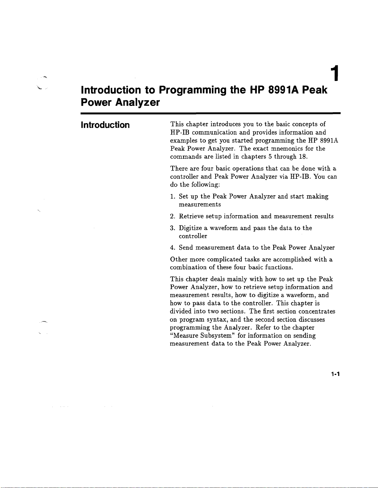
Introduction
This chapter introduces you to the basic concepts of
HP-IB communication and provides information and
examples to get you started programming the HP 8991A
Peak Power Analyzer
commands are listed in chapters 5 through 18.
There are four basic operations that can be done with a
controller and Peak Power Analyzer via HP-IB
do the following:
Set up the Peak Power Analyzer and start making
1.
measurements
Retrieve setup information and measurement results
2.
3.
Digitize a waveform and pass the data to the
controller
Send measurement data to the Peak Power Analyzer
4.
Other more complicated tasks are accomplished with a
combination of these four basic functions.
This chapter deals mainly with how to set up the Peak
Power Analyzer, how to retrieve setup information and
measurement results, how to digitize a waveform, and
how to pass data to the controller
divided into two sections
on program syntax, and the second section discusses
programming the Analyzer
"Measure Subsystem" for information on sending
measurement data to the Peak Power Analyzer
. The exact mnemonics for the
. You can
. This chapter is
. The first section concentrates
. Refer to the chapter
.
1-1

Introduction to Programming the
HP 8991A Peak Power Analyzer
HP 8991A
Controllers Other
Than Hewlett-Packard
The programming examples in this manual are written in
HP BASIC 5
.0 for an HP 9000 Series 200/300 Controller.
HP BASIC handles some of the redundant miscellaneous
overhead associated with IEEE Standard 488
.1 (HP-IB).
For instance, when a BASIC "OUTPUT" statement
is used (by the Active Controller) to send data to an
HP-IB device, the following sequence of commands and
data are sent over the bus:
OUTPUT
1.
The unlisten command is sent.
2.
The talker's address command is sent (the address of
701
;"Data"
the computer).
3.
The listener's address command (01) is sent.
4.
The data bytes "D", "a", "t", and "a" are sent.
5.
Terminators CR and LF are sent.
All bytes are sent using the HP-IB's interlocking
handshake to ensure that the listener has received each
byte.
The example clearly shows that the HP BASIC
"OUTPUT" statement causes more to take place
besides the output of data
. So, for controllers other
than Hewlett-Packard which are using a programming
language other than HP BASIC, additional steps may
have to be added to the program examples given in the
manual.
1-2
For more information, refer to IEEE Standard 488
your programming language reference.
.1 and

Introduction to Programming the
HP 8991A
HP 8991A Peak Power Analyzer
Programming
Syntax
Talking to the Peak
Power Analyzer
In general, computers acting as controllers communicate
with the Peak Power Analyzer by passing messages over
a remote interface using the I/O statements provided
in the instruction set of the controller's host language.
Hence, the messages for programming the Peak Power
Analyzer, described in this manual, will normally appear
as ASCII character strings imbedded inside the I/O
statements of your controller's program
the HP 9000 Series 200/300 BASIC language system uses
the OUTPUT statement for sending program messages
to the Peak Power Analyzer, and the ENTER statement
for receiving response messages from the Peak Power
Analyzer
an output command and passing the device selector,
program message, and terminator
selector ensures that the program message is sent to the
correct interface and instrument.
The following command turns the command headers on:
OUTPUT < device selector >;":SYSTEM :HEADER ON"
< device selector > represents the address of the device
being programmed
. Messages are placed on the bus by using
.
. For example,
. Passing the device
1-3

Introduction to Programming the
HP 8991A Peak Power Analyzer
HP 8991A
Note
Addressing the Peak
Power Analyzer
The programming examples in this manual are written in
HP Basic 5
.0 for an HP 9000 Series 200/300 Controller.
The actual OUTPUT command you use when
programming is dependent on the controller and the
programming language you are using.
Angular brackets "< >," in this manual, enclose words
or characters that symbolize a program code parameter
or a bus command.
Information that is displayed in quotes represents
the actual message that is sent across the bus
. The
message terminator (NL or EOI) is the only additional
information that is also sent across the bus.
For HP 9000 Series 200/300 controllers, it is not
necessary to type in the actual <terminator> at the end
of the program message
. These controllers automatically
supply the program message terminator when the return
key is pressed.
Since HP-IB can address multiple devices through the
same interface card, the device selector passed with
the program message must include not only the correct
interface code, but also the correct instrument address.
1-4
Interface Select Code (Selects Interface).Each interface
card has a unique interface select code
. This code
is used by the controller to direct commands and
communications to the proper interface
. The default is
typically "7" for HP-IB controllers.
Instrument Address (Selects Instrument).Each
instrument on an HP-IB bus must have a unique
instrument address between decimal 0 and 30
. The
address must not be the address of the controller, which
is usually decimal 21
. The device address passed with
the program message must include not only the correct

Introduction to Programming the
HP 8991A
HP 8991A Peak Power Analyzer
instrument address, but also the correct interface select
code.
DEVICE SELECTOR = (Interface Select Code * 100) +
(Instrument Address)
For example, if the instrument address for the Peak
Power Analyzer is 7 and the interface select code is
7, when the program message is passed, the routine
performs its function on the instrument at device
selector 707.
For the Peak Power Analyzer, the instrument address is
typically set to "7" at the factory
. This address can be
changed in the HP-IB menu of the Utility menu.
Note
Program Message
Syntax
The program examples in this manual assume the Peak
Power Analyzer is at device address 707.
To program the Peak Power Analyzer over the bus, you
must have an understanding of the command format
and structure expected by the Peak Power Analyzer.
The Peak Power Analyzer is remotely programmed with
program messages
. These are composed of sequences
of program message units, with each unit representing
a program command or query
. A program command or
query is composed of a sequence of functional elements
that include separators, headers, program data, and
terminators
. These are sent to the Peak Power Analyzer
over the system interface as a sequence of ASCII data
messages
. For example:
1-5

Introduction to Programming the
HP 8991A Peak Power Analyzer
PROGRAM MESSAGE UNIT
HP 8991A
Separator
Command Syntax
OUTPUT XXX
OUTPUT CCNMAND
DEVICE SELECTOR
(OPTIONAL)
PROGRAM MNEMONICS
SPACE SEPARATOR
CHARACTER DATA
; ":SYSTEM
: HEADER ON"
The <separator> shown in the program message refers
to a blank space which is required to separate the
program mnemonic from the program data.
A command is composed of a header, any associated
data, and a terminator. The header is the mnemonic or
mnemonics that represent the operation to be performed
by the Peak Power Analyzer
. The different types of
headers are discussed in the following paragraphs.
Simple Command Header.Simple command headers
contain a single mnemonic
. AUTOSCALE and
DIGITIZE are examples of simple command headers
typically used in the Peak Power Analyzer
. The syntax
is:
1-6
<program mnemonic> <terminator>
When program data must be included with the simple
command header (for example,
separator is added
. The syntax is:
:DIGITIZE CHAN1), a
<program mnemonic> <separator> <program data>
<terminator>

Introduction to Programming the
HP 8991A
HP 8991A Peak Power Analyzer
Compound Command Header.Compound command
headers are a combination of two or more program
mnemonics
. The first mnemonic selects the subsystem,
and the last mnemonic selects the function within that
subsystem
. Additional mnemonics appear between
the subsystem mnemonic and the function mnemonic
when there are additional levels within the subsystem
that must be transversed
the compound message are separated by colons
. The mnemonics within
. For
example:
To execute a single function within a subsystem, use the
following:
<subsystem>
: <function> <separator> <program
data> < terminator>
(For example
:SYSTEM
:LONGFORM ON)
To transverse down a level of a subsystem to execute a
subsystem within that subsystem:
<subsystem>
: <subsystem>
: <function> <separator>
<program data> <terminator>
(For example
:TRIGGER
:DELAY:SOURCE CHAN1)
To execute more than one function within the same
subsystem a semi-colon is used to separate the functions:
<subsystem >
: <function> <separator> <data> ;
<function> <separator> <data> <terminator>
(For example
:SYSTEM
:LONGFORM ON
;HEADER
ON)
Identical function mnemonics can be used for more than
one subsystem
. For example, the function mnemonic
RANGE may be used to change the vertical range or to
change the horizontal range:
:CHANNEL1
-
sets the full scale vertical axis to 7 mW
:RANGE 7E-03
1-7

Introduction to Programming the
HP 8991A Peak Power Analyzer
HP 8991A
Query Command
:TIMEBASE
-
sets the horizontal timebase to 1 second full scale.
CHANNELI
:RANGE
and
TIMEBASE
1
are subsystem selectors
that determine which range is being modified.
Common Command Header
control IEEE 488
.2 functions within the Peak Power
Analyzer (such as clear status, etc
.
Common command headers
.)
. Their syntax is:
*<command header> < terminator>
No space or separator is allowed between the asterisk
and the command header
. *CLS is an example of a
common command header.
Command headers immediately followed by a question
mark (?) are queries. After receiving a query, the
Peak Power Analyzer interrogates the requested
function and places the answer in its output queue.
The output message remains in the queue until it is
read or another command is issued
. When read, the
message is transmitted across the bus to the designated
listener (typically a controller)
:TIMEBASE
:RANGE? places the current timebase
setting in the output queue
. For example, the query
. In conjunction with this,
the controller input statement:
1-8
ENTER <device selector>
;Range$
passes the value across the bus to the controller and
places it in the BASIC variable "Range$".
Query commands are used to find out how the Peak
Power Analyzer is currently configured
. They are
also used to get results of measurements made by
the Peak Power Analyzer, with the query actually
activating the measurement
:MEASURE
:RISETIME? instructs the Peak Power
. For example, the command
Analyzer to measure the risetime of your waveform and
place the result in the output queue.

Introduction to Programming the
HP 8991A
HP 8991A Peak Power Analyzer
Note
Program Header
Options
The output queue must be read before the next program
message is sent
query
query with a program statement like, ENTER 707;
Value_risetime$ to read the result of the query and place
the result in a BASIC variable (Value_risetime$).
Sending another command before reading the result of
the query will cause the output buffer to be cleared and
the current response to be lost. This will also generate
an error in the error queue.
Program headers can be sent using any combination of
uppercase or lowercase ASCII characters
responses, however, are always returned in uppercase.
Both program command and query headers may be
sent in either longform (complete spelling), shortform
(abbreviated spelling), or any combination of longform
and shortform
shortform of a command will be accepted by the Peak
Power Analyzer
the headers on:
:MEASURE
. For example, when you send the
:RISETIME? you must follow that
. Instrument
. Please note, ONLY the longform or
. Either of the following examples turn
Note
:SYSTEM
:SYST
Programs written in longform are easily read and
are almost self-documenting
conserves the amount of controller memory needed for
program storage and reduces the amount of I/O activity.
The rules for shortform syntax are shown in the chapter
"Programming and Documentation Conventions
:HEADER ON - longform
:HEAD ON - shortform
. The shortform syntax
."
1-9

Introduction to Programming the
HP 8991A Peak Power Analyzer
HP 8991A
Program Data
Program data is used to convey a variety of types of
parameter information related to the command header.
At least one space must separate the command header or
query header from the program data.
<program mnemonic> <separator> <data>
<terminator>
When a program mnemonic or query has multiple data
parameters a comma separates sequential program data.
<program mnemonic> <separator> <data>,<data>
<terminator>
For example,:TRIGGER
two data parameters
1
.23E-01 (numeric data).
:DELAY TIME,1
.23E-01 has
: TIME (character data) and
Character Program Data.Character program data
is used to convey parameter information as alpha
or alphanumeric strings
. For example, the timebase
command MODE can be set to auto, trigger, or single.
The character program data in this case may be AUTO,
TRIGGER, or SINGLE.:TIMEBASE
:MODE SINGLE
sets the timebase mode to single.
Program Message
Terminator
1-10
Numeric Program Data.Some command headers
require program data to be a number
:TIMEBASE
:RANGE requires the desired full scale
range to be expressed numerically
. For example,
. The Peak Power
Analyzer recognizes integers, real numbers, and scientific
notation
Communication and System Functions
. For more information see the chapter "Message
."
The program codes within a data message are executed
after the program message terminator is received
. The
terminator may be either an NL (New Line) character,
an EOI (End-Or-Identify) asserted, or a combination
of the two
. All three ways are equivalent with the
exact encodings for the program terminators listed

HP 8991A
Introduction to Programming the
HP 8991A Peak Power Analyzer
in the chapter "Message Communication and System
Functions
line low on the last byte of the data message
." Asserting EOI sets the HP-IB EOI control
. The NL
character is an ASCII linefeed (decimal 10).
Selecting Multiple
Subsystems
Note
Summary
You can send multiple program commands and program
queries for different Peak Power Analyzer subsystems
on the same line by separating each command with a
semicolon. The colon following the semicolon enables
you to enter a new subsystem
<program mnemonic> <separator> <data>
. For example:
;
: <program
mnemonic> <separator> <data> <terminator>
:CHANNELI
:RANGE 0.4;
:TIMEBASE
:RANGE
1
Multiple commands may be any combination of
compound and simple commands.
The following illustration summarizes the syntax for
programming over the bus
.
OUTPUT
XXX
PROGRAM MESSAGE UNIT
; "
: SYSTEM
: HEADER ON"
OUTPUT COMMAND
DEVICE SELECTOR
(OPTIONAL)
PROGRAM MNEMONICS
SPACE SEPARATOR
CHARACTER DATA

Introduction to Programming the
HP 8991A Peak Power Analyzer
HP 8991A
Programming the
Peak Power
Analyzer
Initialization
Note
Autoscale
To make sure the bus and all appropriate interfaces
are in a known state, begin every program with an
initialization statement. For example:
CLEAR 707 ! initializes the interface of the
!
Analyzer.
Then, initialize the Peak Power Analyzer to a preset
state
. For example:
OUTPUT 707
The actual commands and syntax for initializing the
Peak Power Analyzer are discussed in the chapter
"Common Commands
Refer to your controller manual and programming
language reference manual for information on initializing
the interface.
The AUTOSCALE feature of the Peak Power Analyzer
performs a very useful function on unknown waveforms
by setting up the vertical channel, timebase, and trigger
level of the Peak Power Analyzer.
;"*RST" ! initializes the instrument
to a preset state.
."
1-12
The syntax for Autoscale is:
OUTPUT 707;":AUTOSCALE"

Introduction to Programming the
HP 8991A
HP 8991A Peak Power Analyzer
Setting Up the Peak
Power Analyzer
A typical Peak Power Analyzer setup would set the
vertical range, the horizontal range, delay time, delay
reference, trigger mode, trigger level, and trigger slope.
A typical example of the commands sent to the Analyzer
are:
OUTPUT 707;":SYSTEM
OUTPUT
OUTPUT 707 ;"CHANNELI
OUTPUT 707;":TIM
OUTPUT 707;":TRIGGER
707;":CHANNELI :RANGE
This example sets the display units to dBm
reference level is set to 20 dBm
:POWER
:RANG 1E-06 ;DEL 20E-09 ;MODE TRIG"
:UNITS DBM"
20 DBM"
:SPAN 40"
:LEVEL ODBM
;SLOPE POSITIVE"
. The
. With one screen
displayed, the full scale display is 40 dB or 8 dB per
division
ns delay
. The horizontal time is 1 ps full-scale with a 20
. The timebase mode is set to triggered, and the
trigger circuit is programmed to trigger at 0 dBm on a
positive slope
.
1-13

Introduction to Programming the
HP 8991A Peak Power Analyzer
HP 8991A
Returning to Local
Aborting Lengthy
Commands
When placing the Peak Power Analyzer in local,
use the BASIC command LOCAL <interface select
code><device selector> and not LOCAL <device
selector>
. Using only the BASIC command LOCAL
<device selector> returns the front panel of the Peak
Power Analyzer to local, but the Peak Power Analyzer
still accepts remote commands
10 REMOTE 707 !Peak Power Analyzer is
20
30 LOCAL 7
40
50
60 OUTPUT 707;":MENU FREQ"
70
70
80
90
100 LOCAL 707!Peak Power Analyzer accepts
110
!placed in remote.
!Peak Power Analyzer accepts
!remote commands and commands
!from the front panel.
!Send a command
!Peak Power Analyzer still
!accepts commands from the
!front panel.
!commands from the front panel.
. For example:
Under certain conditions, some commands, especially the
Root Level DIGITIZE command, can take a long time
to process
before it is finished
. It may be desired to abort the command
. The following text lists the different
ways that can be used to abort the HP-IB command.
The command that has minimal impact on the existing
instrument state is listed first
. Before any of the
commands can be used, it is necessary to gain control of
the controller by pausing the program or clearing the
interface
. Clearing the interface is done with a dedicated
key (CLEAR I/O) on HP 9000 Series 200 Controllers.
1-14
Begin by using the first command, and then use as many
as needed to abort the command:
ABORT 7
!Minimum change, simply clears the
!handshake lines
. (ABORT message)

Introduction to Programming the
HP 8991A
CLEAR 707 !The input and output buffers
!are cleared, the parser is reset, and any
!pending commands are cleared
!Device Clear message)
CLEAR 7
OUTPUT 707
!The same actions are taken as with
!CLEAR 707, except to all instruments
!on interface select code 7
!Clear message)
;"*RST"
!Peak Power Analyzer is reset to a
!pre-defined state.
HP 8991A Peak Power Analyzer
. (Selective
. (Device
Receiving Information
from the Peak Power
Analyzer
After receiving a query (command header followed by a
question mark), the Peak Power Analyzer interrogates
the requested function and places the answer in its
output queue. The answer remains in the output queue
until it is read or another command is issued
. When
read, the message is transmitted across the bus to the
controller
. The input statement for receiving a response
message from an instrument's output queue typically
has two parameters; the device address and a format
specification for handling the response message
. For
example, to read the result of the query command
:SYSTEM
:LONGFORM?, you would execute the
statement:
ENTER <device selector>
;Setting$
where <device selector> represents the address of your
device
. This would enter the current setting for the
longform command in the string variable Setting$.
1-15
Introduction to Programming the
HP 8991A Peak Power Analyzer
HP 8991A
Note
All results for queries sent in a program message
must be read before another program message
is sent
with the program statement ENTER 707
. For example, when you send the query
:MEASURE
:RISETIME?, you must follow that query
;Risetime$ to
read the result of the query and place the result in a
variable (Risetime$).
Sending another command before reading the result of
the query will cause the output buffer to be cleared and
the current response to be lost. This will also cause an
error to be placed in the error queue
. Executing an
ENTER statement before sending a query will cause the
controller to wait indefinitely.
The actual ENTER program statement you use when
programming is dependent on the programming language
you are using.
The format specification for handling the response
message is dependent on both the controller and the
programming language.
Response Header
1-16
Options
The format of the returned ASCII string depends on
the current settings of the SYSTEM HEADER and
LONGFORM commands
<header><separator><data><terminator>
. The general format is:
The header identifies the data that follows and is
controlled by issuing a
command
. If the state of the header command is OFF,
only the data is returned by the query
the header is controlled by the
ON/OFF command
be in its shortform
from a
:MEASURE
:SYSTEM
:HEADER ON/OFF
. The format of
:SYSTEM
:LONGFORM
. If longform is OFF, the header will
. The following would be returned
:FREQUENCY? query:
<data><terminator> (with HEADER OFF )
Introduction to Programming the
HP 8991A
HP 8991A Peak Power Analyzer
Note
Response Data
Formats
:MEAS
:FREQ<separator> <data> <terminator>
(with HEADER ON/LONGFORM OFF )
:MEASURE
:FREQUENCY<separator> <data>
<terminator> (with HEADER ON/LONGFORM ON )
A command or query may be sent in either longform
or shortform, or in any combination of longform and
shortform
. The HEADER and LONGFORM commands
only control the format of the returned data and have
no effect on the way commands are sent
. Common
commands never return a header.
Refer to the chapter "System Subsystem" for more
information on turning the HEADER and LONGFORM
commands on and off.
Most data will be returned as exponential or integer
numbers
setups is returned as character data
. However, query data of some instrument
. Interrogating the
trigger SLOPE? will return one of the following:
.'T'D
T!''L,D
.CT
1'1DL' DACVT,TTTL
n
i+,...«.:.... +,...~ (...
HEADER ON/ LONGFORM ON)
:+L.
Note
:TRIG
:SLOP POS<terminator> (with HEADER
ON/LONGFORM OFF)
POSITIVE<terminator> (with HEADER
OFF/LONGFORM ON)
POS<terminator> (with HEADER
OFF/LONGFORM OFF)
Refer to the individual commands in this manual for
information on the format (alpha or numeric) of the data
returned from each query
.
1-17

Introduction to Programming the
HP 8991A Peak Power Analyzer
HP 8991A
String Variables
Note
Note
If you want to observe the headers for queries, you must
bring the returned data into a BASIC string variable.
Reading queries into string variables is simple and
straightforward, requiring little attention to formatting.
For example:
ENTER <device selector>
;Result$
places the output of the query in the string variable
Result$.
BASIC string variables are case sensitive and must be
expressed exactly the same each time they are used.
The output of the Peak Power Analyzer may be numeric
or character data depending on what is queried. Refer to
the specific commands for the formats and types of data
returned from queries.
For the example programs, assume that the device
being programmed is at device selector 707
. The actual
address will vary according to how you have configured
the bus for your own application.
1-18
The following example shows the data being returned to
a string variable with headers off:
10 DIM Rang$[30]
;"
20 OUTPUT 707
30 OUTPUT 707
40 ENTER 707
:SYSTEM
;"
:CHANNELl
;Rang$
:HEADER OFF"
:RANGE?"
50 PRINT Rang$
60 END
After running this program, the controller displays:
+2
.00000E+01

Introduction to Programming the
HP 8991A
HP 8991A Peak Power Analyzer
Numeric Variables
Note
If you do not need to see the headers when a numeric
value is returned from the Peak Power Analyzer , then
you can use a numeric variable
. When you enter numeric
data from the Peak Power Analyzer into a numeric
variable, turn the headers off.
When you enter numeric data from the Peak Power
Analyzer into numeric variables, the headers should
be turned off
. Otherwise the headers may cause
misinterpretation of returned data.
The following example shows the data being returned to
a numeric variable.
10 OUTPUT 707;":SYSTEM
20 OUTPUT 707;":CHANNEL1
30 ENTER 707
40 PRINT Rang
50 END
;Rang
:HEADER OFF"
:RANGE?"
After running this program, the controller displays:
20
Definite-Length
Block Response
Data
Definite-length block response data allows any type of
device-dependent data to be transmitted over the system
interface as a series of 8-bit binary data bytes
.' This is
particularly useful for sending large quantities of data.
The syntax is a pound sign ( # ) followed by a non-zero
digit representing the number of digits in the decimal
integer
. After the non-zero digit is the decimal integer
that states the number of 8-bit data bytes being sent.
This is followed by the actual data.
For example, in order to transmit 80 bytes of data, the
syntax would be:
1-19

Introduction to Programming the
HP 8991A Peak Power Analyzer
NUMBER OF DIGITS
THAT FOLLOW
ACTUAL DATA
#800000080<eighty bytes of data><terminator>
NUMBER OF BYTES
TO BE TRANSMITTED
HP 8991A
16500803
The first"8"after the # sign states the number of digits
that follow, and "00000080" states the number of bytes
(in decimal) to be transmitted.
1-20
Multiple Queries
You can send multiple queries to the Peak Power
Analyzer within a single program message, but you must
also read them back within a single program message.
This can be accomplished by either reading the queries
back into a string variable or into multiple numeric
variables
query
. For example, you could read the result of the
:SYSTEM
:HEADER?
;LONGFORM?
into the
string variable Results$ with the command:
ENTER 707
;Results$
When you read the result of multiple queries into
string variables, each response is separated by a
semicolon
:SYSTEM
and
. For example, the response of the query
:HEADER?
LONGFORM
:SYSTEM
:HEADER 1;:SYSTEM
;LONGFORM?
on would be:
:LONGFORM
with
HEADER
1
If you do not need to see the headers when the
numeric values are returned, then you can use

Introduction to Programming the
HP 8991A
HP 8991A Peak Power Analyzer
the following program message to read the query
:SYSTEM
:HEADERS?
;LONGFORM? into multiple
numeric variables:
Note
Instrument Status
Digitize Command
ENTER 707
; Result1,Result2
When you enter numeric data into numeric variables, the
headers should be turned off
. Otherwise, the headers
may cause formatting errors or misinterpretation of
returned data.
Status registers track the current status of the Peak
Power Analyzer
. By checking the instrument status, you
can find out whether an operation has been completed,
whether the Peak Power Analyzer is receiving triggers,
and more. The chapter "Message Communication and
System Functions" explains how to check the status of
the instrument.
The ACQUIRE and WAVEFORM subsystems are
subsystems that affect the DIGITIZE command
. The
DIGITIZE command is used to capture a waveform in
a known format which is specified by the ACQUIRE
subsystem
. When the DIGITIZE command is sent to
the Peak Power Analyzer, the specified channel signal
is digitized with the current ACQUIRE parameters.
To obtain waveform data, you must specify the
WAVEFORM parameters for the waveform data prior to
sending the
:WAVEFORM
:DATA? query.
The number of data points comprising a waveform varies
according to the number requested in the ACQUIRE
subsystem
. The ACQUIRE subsystem determines
the number of data points, type of acquisition, and
number of averages used by the DIGITIZE command.
This allows you to specify exactly what the digitized
information will contain
OUTPUT 707;":ACQUIRE
. A typical setup is:
:TYPE
AVERAGE"
1-21

Interface Functions
HP 8991A
OUTPUT 707;":ACQUIRE
OUTPUT 707;":WAVEFORM
OUTPUT 707;":WAVEFORM
OUTPUT 707;":ACQUIRE
OUTPUT 707;":ACQUIRE
OUTPUT 707;":DIGITIZE CHANNEL1"
OUTPUT 707;":WAVEFORM :DATA?"
:COMPLETE 100"
:SOURCE CHANNEL1"
:FORMAT ASCII"
:COUNT 4"
:POINTS 500"
This setup places the Peak Power Analyzer into the
average mode with four averages and defines the data
record to be 500 points
. This means that when the
DIGITIZE command is received, the waveform is not
stored in memory until 500 points have been averaged at
least four times.
After receiving the
:WAVEFORM :DATA?
query, the
Peak Power Analyzer starts outputting the waveform
information when addressed to talk.
Digitized waveforms are transferred from the Peak
Power Analyzer to the controller by sending a numerical
representation of each digitized point
. The format of
the numerical representation is controlled with the
:WAVEFORM
as ASCII,
:FORMAT
WORD,
command and may be selected
BYTE, or
COMPRESSED.
1-22
The easiest method of entering a digitized waveform
from the Peak Power Analyzer is to use the ASCII
format and place the information in an integer array.
The data point is represented by signed six-digit integers
whose values range from 0 to 32,640
. You must scale the
integers with values from a waveform header (separately
queried) to determine the amplitude value of each point.
These integers are passed starting with the leftmost
point on the Peak Power Analyzer's display. For more
information, refer to the chapter "Waveform Subsystem
."

2
Interface Functions
Introduction
Interface
Capabilities
Command and
Data Concepts
This section describes the interface functions and
some general concepts of the HP-IB
functions are defined by IEEE 488.1. They deal with
general bus management issues, as well as messages
which can be sent over the bus as bus commands.
The interface capabilities of the Peak Power Analyzer, as
defined by IEEE 488
PP1, DC1, DTI, CO, and E2.
The HP-IB has two modes of operation
and data mode
ATN line is true
talk and listen addresses and various bus commands,
such as a group execute trigger (GET)
data mode when the ATN line is false
is used to convey device-dependent messages across the
bus
. The device-dependent messages include all of the
instrument commands and responses found in chapters 5
through 18 of this manual.
.1 are SH1, AH1, T5, L4, SRI, RL1,
. The bus is in command mode when the
. The command mode is used to send
. In general, these
: command mode
. The bus is in the
. The data mode
2-1

Interface Functions
Addressing
Addressed Mode
HP 8991A
By using the front-panel menus, the Peak Power
Analyzer can be placed in either talk-only mode or
addressed (talk/listen) mode (see your Operating
Manual).
Addressed mode is used when the Peak Power Analyzer
will operate in conjunction with a controller
the Peak Power Analyzer is in the addressed mode, the
following is true:
n
Each device on the HP-IB bus resides at a particular
address, ranging from 0 to 30
reserved for the controller.
nThe active controller specifies which devices will talk
and which will listen.
n
An instrument, therefore, may be talk-addressed,
listen-addressed, or unaddressed by the controller.
If the controller addresses the instrument to talk, it will
remain configured to talk until it receives an interface
clear message (IFC), another instrument's talk-address
(OTA), its own listen address (MLA), or a universal
untalk command (UNT).
. Address 21 is usually
. When
2-2
Talk-Only Mode
If the controller addresses the instrument to listen, it
remains configured to listen until it receives an interface
clear message (IFC), its own talk-address (MTA), or a
universal unlisten command (UNL).
Refer to the BASIC I/O documentation for more
information on these messages.
Talk-only mode is used when you want to make a
hardcopy of the Peak Power Analyzer display using an
HP-IB listen-only printer.

HP 8991A
Remote, Local
and Local Lockout
Note
Interface Functions
The local, remote, and remote with local lockout modes
may be used for various degrees of front-panel control
while a program is running
will accept and execute bus commands while in local
mode, and the front panel will also be entirely active
the Peak Power Analyzer is in remote mode, all controls
(except the power switch and the LOCAL key) are
entirely locked out
by the controller or pressing the front-panel LOCAL key.
Cycling the power will also restore local control, but this
will also reset certain HP-IB states.
The Peak Power Analyzer is placed in remote mode by
first setting the REN bus control line true, and then
addressing the instrument to listen
Analyzer can be placed in local lockout mode by sending
the local lockout command (LLO)
Analyzer is returned to local mode by either setting the
REN line false, sending the instrument the go-to-local
command (GTL), or simulating a front-panel LOCAL
key press using the SYSTEM
. Local control can only be restored
. The Peak Power Analyzer
. The Peak Power
. The Peak Power
:KEY command.
. If
Bus Commands
The following commands are IEEE 488
(ATN true)
which are taken when these commands are received by
the Peak Power Analyzer.
. IEEE 488
.2 defines many of the actions
.1 bus commands
2-3

Interface Functions
Device Clear
Group Execute
Trigger (GET)
Interface Clear (IFC)
Status
Annunciators
HP 8991A
The device clear (DCL) or selected device clear (SDC)
commands clear the input and output buffers, reset the
parser, and clear any pending commands.
The group execute trigger command arms the trigger
(which is the same action produced by sending the RUN
command).
This command halts all bus activity. This includes
unaddressing all listeners and the talker, disabling serial
poll on all devices, and returning control to the system
controller.
The Peak Power Analyzer will display the HP-IB status
on the CRT
instrument is in remote mode, whether talk or listen is
addressed, and whether the Peak Power Analyzer has
requested service
local mode only the SRQ annunciator may be displayed.
. The message will indicate whether the
. When the Peak Power Analyzer is in
2-4

3
Message Communication
and System Functions
Introduction
Protocols
This chapter describes the operation of instruments that
operate in compliance with the IEEE 488
Instruments that are compatible with IEEE 488
also be compatible with IEEE 488
488
.1 compatible instruments may or may not conform
to the IEEE 488
defines the message exchange protocols by which the
instrument and the controller will communicate
defines some common capabilities, which are found in
all IEEE 488
a few items which are not specifically defined by IEEE
488
.2, but deal with message communication or system
functions.
The protocols of IEEE 488
scheme used by the controller and the instrument
to communicate
appropriate for devices to talk or listen and what
happens when the protocol is not followed.
.2 standard
.2 instruments
. This includes defining when it is
. The IEEE 488
. This chapter also contains
.2 define the overall
.1
.2 standard.
.2 must
. However IEEE
.2 standard
. It also
Functional Elements
Before proceeding with the description of the protocol, a
few system components should be understood.
Input Buffer.The input buffer of the instrument is the
memory area where commands and queries are stored
prior to being parsed and executed
to send a string of commands to the instrument which
. It allows a controller
3-1

Message Communication
and System Functions
HP 8991A
could take some time to execute, and then proceed to
talk to another instrument while the first is parsing and
executing commands
. The Peak Power Analyzer's input
buffer will hold 300 characters, or bytes of data.
Protocol Overview
Output Queue
.
The output queue of the instrument is
the memory area where all output data (<response
messages>) are stored until read by the controller.
The Peak Power Analyzer's output queue will hold 300
characters. However, the Peak Power Analyzer will
handle block data of greater than 300 characters where
appropriate.
Parser.The instrument's parser is the component
that interprets the commands sent to the instrument
and decides what actions should be taken
. "Parsing"
refers to the action taken by the parser to achieve
this goal
. Parsing and executing of commands begins
when either the instrument sees a <program message
terminator> (defined later in this chapter) or the input
buffer becomes full
. If you wish to send a long sequence
of commands to be executed and talk to another
instrument while they are executing, you should send all
of the commands before sending the <program message
terminator>.
The instrument and controller communicate by using
<program message>s and <response message>s. These
messages serve as the containers into which sets of
program commands or instrument responses are placed.
<program message>s are sent by the controller to the
instrument, and <response message>s are sent from
the instrument to the controller in response to a query
message
. A "query message" is defined as being a
<program message> which contains one or more queries.
The instrument will only talk when it has received a
valid query message, and, therefore, has something
to say
. The controller should only attempt to read a
response after sending a complete query message, but
3-2

Message Communication
HP 8991A
and System Functions
Protocol Operation
before sending another <program message>
. The basic
rule to remember is that the instrument will only talk
when prompted to, and the output queue must be read
before the instrument is told to do something else.
When the instrument is powered on or when it receives
a device clear command, the input buffer and output
queue are cleared, and the parser is reset to the root
level of the command tree.
The instrument and the controller communicate
by exchanging complete <program message>s and
<response message>s
. This means that the controller
should always terminate a <program message> before
attempting to read a response
. The instrument will
terminate <response message>s except in talk-only
mode during a hardcopy output.
If a query message is sent, the next message passing
over the bus should be the <response message>
. The
controller should always read the complete <response
message> associated with a query message before
sending another <program message> to the same
instrument.
The instrument allows the controller to send multiple
queries in one query message
sending a "compound query
. This is referred to as
." As will be noted later in
this chapter, multiple queries in a query message are
separated by semicolons
. The responses to each of the
queries in a compound query will also be separated by
semicolons.
Commands are executed in the order that they are
received
execute trigger (GET) bus command
. This also applies to the reception of the group
. The group execute
trigger command should not be sent in the middle of a
<program message>
.
3-3

Message Communication
and System Functions
HP 8991A
Protocol Exceptions
If an error occurs during the information exchange, the
exchange may not be completed in a normal manner.
Some of the protocol exceptions are shown below.
Addressed to talk with nothing to say
.
If the instrument
is addressed to talk before it receives a query, it will
indicate a "query unterminated" error and will not send
any bytes over the bus
; in addition, the bus will hang.
If the instrument has nothing to say because queries
requested were unable to be executed because of some
error, the device will not indicate a query error, it
will simply wait to receive the next message from the
controller.
Addressed to talk with no listeners on the bus
. If
the instrument is addressed to talk, and there are no
listeners on the bus, the instrument will wait for a
listener to listen or for the controller to take control.
Command Error
.
A command error will be reported if the
instrument detects a syntax error or an unrecognized
command header.
Execution Error
.
An execution error will be reported if a
parameter is found to be out of range, or if the current
settings do not allow execution of a requested command
or query.
3-4

Message Communication
HP 8991A
and System Functions
Note
When a command is found to have a parameter out of
range, a serial poll immediately following the command
occasionally may not immediately indicate an error.
Processing of the next command begins before the
previous error is reported
. If it is necessary to know
that an error has occurred after each message unit, a
wait statement of one milli-second can be included in
the program to allow the Peak Power Analyzer time to
report the error.
The Peak Power Analyzer was designed to operate
without the wait statement in order to increase overall
bus throughput.
Device-specific Error.A
device-specific error will
be reported if the instrument is unable to execute a
command for a strictly device-dependent reason.
Query Error
protocol for reading a query is not followed
.
A query error will be reported if the proper
. This
includes the interrupted and unterminated conditions
described below.
Unterminated Condition.If the controller attempts
to read a
. <response message> before terminatin
<program message>, a query error will be generated.
The parser will reset itself, and the response will be
cleared from the output queue of the instrument
without being sent over the bus
. This condition also
happens if the instrument is addressed to talk and it
has nothing to say.
g
the
Interrupted Condition.If the controller does not read
the entire <response message> generated by a query
message and then attempts to send another <program
message>, the device will generate a query error
. The
unread portion of the response will then be discarded
by the instrument
message> will not be affected
. The interrupting <program
.
3-5

Message Communication
and System Functions
HP 8991A
Buffer Deadlock.The instrument may become
deadlocked if the input buffer and output queue
both become full
. This condition can occur if a very
long <program message> is sent containing queries
that generate a great deal of response data
. The
instrument cannot accept any more bytes, and the
controller cannot read any of the response data until it
has completed sending the entire <program message>.
Under this condition, the instrument will break the
deadlock by clearing the output queue and continuing
to discard responses until it comes to the end of the
current <program message>. The query error bit will
also be set.
Syntax Diagrams
The syntax diagrams in this chapter are similar to
the syntax diagrams in the IEEE 488
.2 standard.
Commands and queries are sent to the instrument as a
sequence of data bytes
. The allowable byte sequence for
each functional element is defined by the syntax diagram
that is shown with the element description.
The allowable byte sequence can be determined by
following a path in the syntax diagram
. The proper path
through the syntax diagram is any path that follows
the direction of the arrows
element, that element is optional
. If there is a path around an
. If there is a path from
right to left around one or more elements, that element
or those elements may be repeated as many times as
desired.
3-6

Message Communication
HP 8991A
and System Functions
Syntax Overview
This overview is intended to give a quick glance at the
syntax defined by IEEE 488
. It should allow you to
.2
understand many of the things about the syntax that
you need to know
of the IEEE 488
. This chapter also contains the details
.2 defined syntax.
IEEE 488.2 defines the blocks used to build messages
which are sent to the instrument
. A whole string of
commands can, therefore, be broken up into individual
components.
Figure 3-1 shows a breakdown of an example <program
message>
1.
A semicolon separates commands from one another.
. There are a few key items to notice:
Each <program message unit> serves as a container
for one command
. The <program message unit>s are
separated by a semicolon.
2.
A <program message> is terminated by a <NL>
(new line), a <NL> with EOI asserted, or EOI
being asserted on the last byte of the message
. The
recognition of the <program message terminator>,
or <PMT>, by the parser serves as a signal for
l
1 - -
--•
1•
R17 -
] -
<PMT> also affects command tree traversal (see
the Programming and Documentation Conventions
chapter).
3.
Multiple data parameters are separated by a comma.
4.
The first data parameter is separated from the header
with one or more spaces.
5.
The header MEAS
:SOURCE is a compound header.
It places the parser in the measure subsystem until
the <NL> is encountered.
6.
A colon after a semicolon places the parser at the root
level of the command tree.
3-7

Message Communication
and System Functions
HP 8991A
MEAS
:SOURCE CHAN1 ; TVERtical? 1
<program message unit><program message unit separator>
MEAS
:SOURCE CHAN1
<program message>
.0m,3 4 L>
` <program message terminator>
3-8
<decimal numeric program data>
1
.0
Figure 3-1
. <program message> Parse Tree
<suffix program data>
m
<suffix mui U
m

Message Communication
HP 8991A
and System Functions
Device Listening
Syntax
The listening syntax of IEEE 488.2 is designed to be
more forgiving than the talking syntax
. This allows
greater flexibility in writing programs, as well as allowing
them to be easier to read.
Upper/Lower Case Equivalence
letters are equivalent. The mnemonic
same semantic meaning as the mnemonic
<white space>
<white space> is defined to be one or
.
Upper and lower case
.
RANGE
range.
has the
more characters from the ASCII set of 0-32 decimal,
excluding 10 decimal (NL)
. <white space> is used by
several instrument listening components of the syntax.
It is usually optional, and can be used to increase the
readability of a program.
Figure
<program message>
complete message to be sent to the instrument
3-2_ white
The <program message> is a
.
space>
. The
instrument will begin executing commands once it has
a complete <program message>, or when the input
buffer becomes full
. The parser is also repositioned to
the root of the command tree after executing a complete
<program message>
. Refer to the Tree Traversal Rules
in the Programming and Documentation Conventions
chapter for more details
.
3-9

Message Communication
and System Functions
<program
message unit
separator>
HP 8991A
<program
message
Figure 3-3
unit>
. <program message>
<program message unit>
S412a/BL99
<program
message
terminator>
.
The <program message
unit> is the container for individual commands within a
<program message>.
Figure 3-4
. <program message unit>
3-10

Message Communication
HP 8991A
<command
roggrram
eader>
<program data
separator>
=Err
hea
separator>
<program data>
Figure 3-5. <command message unit>
and System Functions
Figure 3-7
separates <program message unit>s, or individual
commands.
<command program header>/<query program
header>
commands or queries
.
These elements serve as the headers of
. They represent the action to be
taken.
<white
. <program message unit separator>
space>
3-11

Message Communication
and System Functions
HP 8991A
<white space>
<simple command
program header>
<compound command
program header>
<common command
program header>
e4ILO#
.44
Where <simple command program header> is defined as
<program
mnemonic>
5412a/BL45
Where <compound command program header> is
defined as
►
-
3-12
Figure 3-8
<program
mnemonic>
. <command program header>
<program
mnemonic>
x148

Message Communication
HP 8991A
and System Functions
Where <common command program header> is defined
as
<program
mnemonic>
54120/8L45
Where <program mnemonic> is defined as
<upper/lower
case alpha>
<upper/lower
case alpha>
Figure 3-8
<digit>
Mlto/ie
Where <upper/lower case alpha> is defined as a single
ASCII encoded byte in the range 41-5A, 61-7A (65-90,
97-122 decimal).
Where <digit> is defined as a single ASCII encoded
byte in the range 30-39 (48-57 decimal).
Where (_) represents an "underscore", a single ASCII-
encoded byte with the value 5F (95 decimal).
. <command program header> (continued)
3-13

Message Communication
and System Functions
HP 8991A
TF <white space>
<simple query
program header>
<compound query
program header>
<carmen query
program header>
541la/0
.4S
Where <simple query program header> is defined as
<program
mnemonic>
Where <compound query program header> is defined as
3-14
<program
mnemonic>
<program
mnemonic>
Where <common query program header> is defined as
<program
mnemonic>
Figure 3-9
. <query program header>

Message Communication
HP 8991A
and System Functions
<program data>
The <program data> element
.
represents the possible types of data which may be sent
to the instrument
the following data types
. The Peak Power Analyzer will accept
: <character program data>,
<decimal numeric program data>, <suffix program
data>, <string program data>, and <arbitrary block
program data>.
Figure 3-10
Figure 3-11
. <program data>
<program
mnemonic>
. <character program data>
3-15

Message Communication
and System Functions
HP 8991A
<mantissa>
<white space>
Where <mantissa> is defined as
(optional
digit>
<digit>
Where <optional digits> is defined as
-0-
/
n
<exponent,
ow
<digit>
<o tione1
Sigit>
3-16
Where <exponent> is defined as
white space>
Figure 3-12. <decimal numeric program data>
O
<digit>

Message Communication
HP 8991A
and System Functions
spaea>
<whlta
-
Figure 3-13
Suffix Multiplier
.
The suffix multipliers that the Peak
(suffix molt)
. <suffix program data>
<suffix unit>
T
►
Power Analyzer will accept are shown in table 3-1.
Suffix Unit
Table 3-1
Value
Mnemonic
1E15
1E12
1E9
1E6
.
The suffix units that the Peak Power
. <suffix mult>
Value
PE
T
1E-3
1E-6
G 1E-9
MA
1E-12
11E-181A
Mnemonic
M
U
N
P
Analyzer will accept are shown in table 3-2.
-T►
Table 3-2
Suffix
Referenced Unit
V
S
W
DBM
DB
HZ
. <suffix unit>
Volt
Second
Watt
dBm
dB
Hertz
3-17

Message Communication
and System Functions
HP 8991A
3-18
Where <inserted'> is defined as a single ASCII
character with the value 27 (39 decimal).
Where <non-single quote char> is defined as a single
ASCII character of any value except 27 (39 decimal).
Where <inserted"> is defined as a single ASCII
character with the value 22 (34 decimal).
Where <non-double quote char> is defined as a single
ASCII character of any value except 22 (34 decimal).
Figure 3-14
. <string program data>

Message Communication
HP 8991A
and System Functions
<8-bit
data byte>
<8-bit
data byte>
<digit>
. `
.
Where <non-zero digit> is defined as a single ASCII
encoded byte in the range 31-39 (49-57 decimal).
Where <8-bit byte> is defined as an 8-bit byte in the
range 00-ff (0-255 decimal).
Figure 3-15
. <arbitrary block program data>
3-19

Message Communication
and System Functions
HP 8991A
<program data separator>
.
A comma separates multiple
data parameters of a command from one another.
<white
space>
Figure 3-16
. <program data separator>
<program header separator>.A
<white space>
space (ASCII decimal
32) separates the header from the first or only parameter
of the command
.
<white space>
3-20
Figure 3-17
. <program header separator>
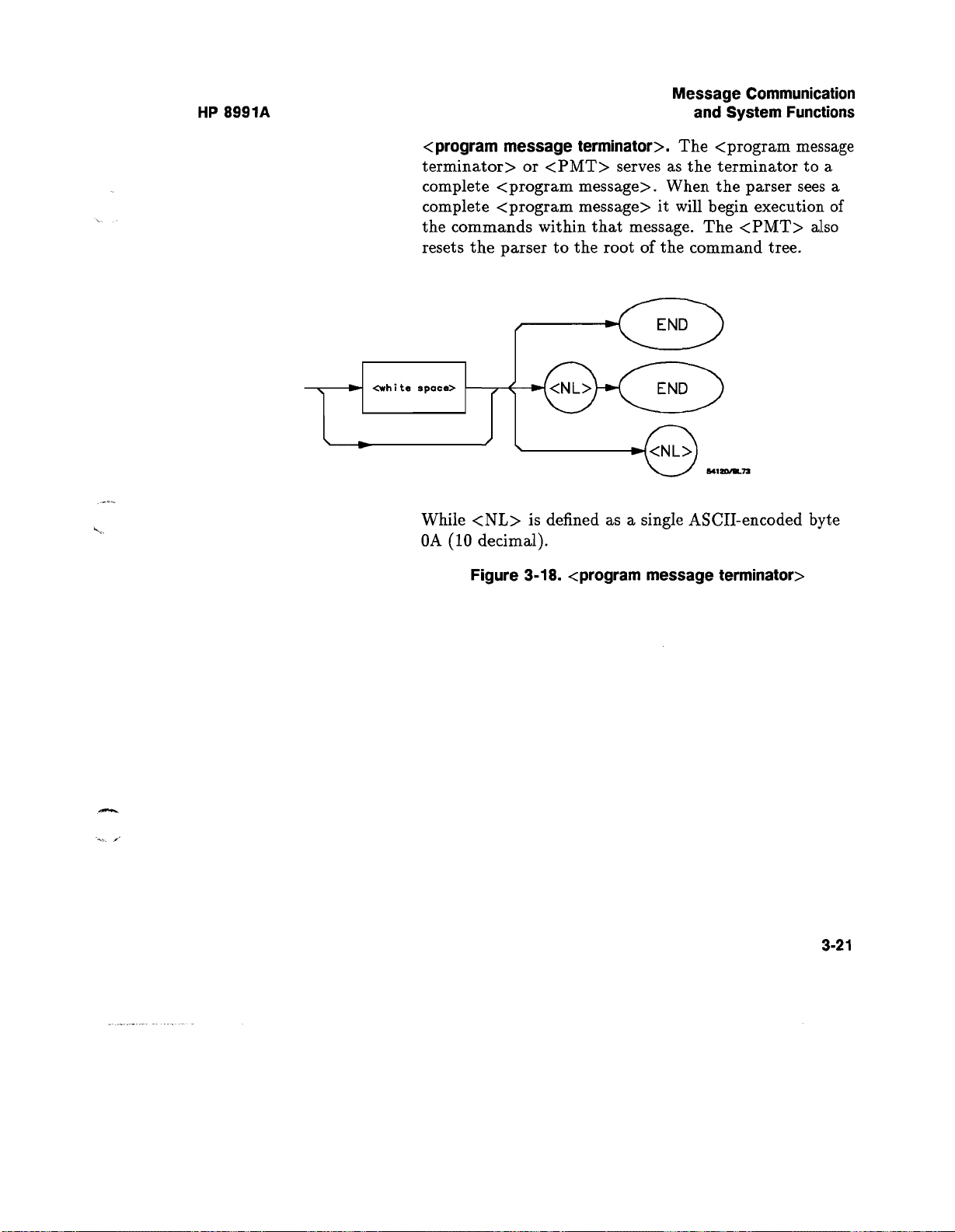
HP 8991A
Message Communication
and System Functions
<program message terminator>
.
The <program message
terminator> or <PMT> serves as the terminator to a
complete <program message>
. When the parser sees a
complete <program message> it will begin execution of
the commands within that message
. The <PMT> also
resets the parser to the root of the command tree.
While <NL> is defined as a single ASCII-encoded byte
OA (10 decimal).
Figure 3-18
. <program message terminator>
3-21

Message Communication
and System Functions
:MEAS
<response message>
:SOUR CHAN1
:MEAS
:TVER -2
.5E-2 <NL>
HP 8991A
<response message unit>
Z
:MEAS
:SOUR CHAN1
<response mnemonic>
MEAS
<response mnemonic>
Figure 3-19
<character response data>
SOUR
. <response message Tree>
<response data>
CHAN1
CHAN1
3-22

Message Communication
HP 8991A
and System Functions
:MEAS
:SOUR CHAN1
<response
MEAS
header>
: TVER
T
<response mnemonic>
MEAS
Figure 3-19. <response message Tree> (continued)
<response
message>
:MEAS
:TVER -2
<response header separator>
<response mnemonic><nr3 numeric response data>
TVER
.5E-2 <NL>
sp
<response data>
-2
-2 .5E-2
.5E-2
Device Talking Syntax
The talking syntax of IEEE 488.2 is designed to be
more precise than the listening syntax
. This allows the
programmer to write routines which can more easily
interpret and use the data the instrument is sending.
One of the implications of this is the absence of <white
space> in the talking formats
. The instrument will not
pad messages which are being sent to the controller with
spaces
.
3-23

Message Communication
and System Functions
HP 8991A
<response message>
complete response from the instrument
.
This element serves as a
. It is the result
of the instrument executing and buffering the results
from a complete <program message>. The complete
<response message> should be read before sending
another <program message> to the instrument.
54120/9157
Figure 3-20
<response message unit>
. <response message>
.
This element serves as the
container of individual pieces of a response
a <query message unit> will generate one <response
message unit>, although a <query message unit> may
generate multiple <response message unit>s.
. Typically,
3-24
<response header>
.
The <response header>, when
returned, indicates what the response data represents.

Message Communication
HP 8991A
<simple
leresponse
header>
<compound
response
header>
<can non
response
header>
641eo/e
.ee
and System Functions
Where <simple response mnemonic> is defined as
<response
mnemonic>
54120/BL59
Where <compound response header> is defined as
(response
nnenwnlc>
<reeponee
mlemonio>
Where <common response header> is defined as
<response
mnemonic>
&417a/L61
Figure 3-21
. <response message unit>
H
3-25

Message Communication
and System Functions
HP 8991A
Where <response mnemonic> is defined as
<upper
case alpha>
<upper
case alpha>
<digit>
asi
:oraet
Where <uppercase alpha> is defined as a single ASCII
encoded byte in the range 41-5A (65-90 decimal).
Where (_) represents an "underscore", a single ASCII
encoded byte with the value 5F (95 decimal).
Figure 3-21
<response data>
. <response message unit> (continued)
.
The <response data> element
represents the various types of data which the
instrument may return
. These types include
: <character
response data>, <nrl numeric response data> (integer),
<nr3 numeric response data> (exponential), <string
response data>, <definite length arbitrary block
response data>, and <arbitrary ASCII response data>.
3-26

Message Communication
HP 8991A
<response
mnemonic>
and System Functions
Figure 3-22
Figure 3-23
. <character response data>
. <nrl numeric response data>
<digit>
<digIt>
Figure 3-24. <nr3 numeric response data>
<digit>
3-27

Message Communication
and System Functions
HP 8991A
Figure 3-25
<non-zero
digit>
Figure 3-26
. <string response data>
<digit>
. <definite length arbitrary block>
<8-bit
data byte>
541ta/e
.l7
3-28
 Loading...