


Testing the Agilent Technologies 8960 for Operational Verification
• The Agilent 8960 can be very difficult to t est for proper function and
operational verification. The complex types of tests used in cellular
manufacturing and the multi-functional design of the 8960 makes it very
difficult to uncover potential operational problems.
It is important to note that a f airly rigid process should be followed for any
testing of the 8960 for functionality and calibration. Many of the 8960 circuits
are designed to work as independent test tools. There is no single pr ogram
that can be run to check everything so a step process is described in this
document to make testing easy and thorough.
By following the Verification / Adjustment Test Record Guide (s ee next page)
and using the instructions provided for each step , you should be ab le to
easily check out any 8960 and be assured of its functional performance.
Verification
If a 8960 should fail the test sequ ence please include a copy of the
Test Record with any unit returned to Agilent Technologies.
Many products are returned to Agilent Te chnologies for repair or
Calibration with no atta ched information regarding any failures observed
or work requested. Consequently there are many instances of equipment
returned to customers with inadequate repairs and ‘No Trouble Found’
classifications. The more information Agilent Technologies receives
regarding a failure the more likely it is to be pr operly repaired.
1

Operational Verification
Functional Verification with 8935 E6382 Expected Limit (Note 1) Pass Fail
Analog Generator Level Accy
Analog Generator Spectral Purity
Harmonics
Sub-Harmonics
Analog Audio Generator Accuracy
GSM Generator
Amplitude Flatness
Peak Phase Error
RMS Phase E rro r
Frequency Error
Analog Audio Analyzer Accuracy
Analog Analyzer RF Power Meter
GSM Analyzer Frequency Measurement Accy.
GSM Analyzer Residual Phase Error
RMS Error
Peak Error
GSM An alyze r PV T Accy Expected Limit (Note 1) Pass Fail
PVT Offset 0usec and 542.8usec
PVT Offset -10usec
PVT Offset 552.8usec
GSM Analyzer ORFS Measurement Expected Limit (Note 1) Pass Fail
ORFS Offset ± 100 kHz (-9 dB) <± 3 dB
ORFS Offset ± 200 kHz (-36 dB) <± 3 dB
ORFS Offset ± 250 kHz (-41 dB) <± 3 dB
ORFS Offset ± 400 kHz (-70 dB) <± 3 dB
ORFS Offset ± 600 kHz (-79 dB) <± 3 dB
ORFS Offset ± 800 kHz (-81 dB) <± 3 dB
ORFS Offset ± 1000 kHz (-81 dB) <± 3 dB
ORFS Offset ± 1200 kHz (-82 dB) <± 3 dB
± 2.0 dB
≤ -25 dBc
≤ -40 dBc
± 0.03V
± .6 dBm
(PGSM/EGSM)
(DCS/PCS)
< ± 4 Deg
< ± 6 Deg
< ± 2 Deg.
(18 Hz) < ± .04 ppm
± 0.04V
± 1.6 dBm
< ± 24 Hz
< ± 2 Deg
< ± 8 Deg
(0 dB) ± 2 dB
≤ 8 dB
≤ 8 dB
Verification
Note 1 - Expected test limit levels may vary according to test instrument
source used. Expected limits listed may require modification.
Optional Verification with Phone (Call Processing)
Phone Testing Pass Fail
Mobil e Stat ion Origination
Base St ation O rigin ation
Traffic Channel Handover
Mobile Transmit Level Handover (levels between 5 and 15)
Mobile Transmit Timing Advance Handover
Mobile Transmit Time Slot Handover (timeslots between 3 and 5)
Dual Band Handoff (PGSM to DCS)
2

Operational Verification
Test Equipment Setup
The test equipment required for Operat ional Verification is:
Agilent ESG E4433B Digital Signal Generator with Opt: UN8
Agilent VSA E4406A Transmitter Tester with Opt: BAH
Laptop PC with Visual Basic capability and GPIB card
There is automated software available on the Momentum Support CD-ROM.
The software fully automates the following verification procedure. The software
title is “8960Verify”. See the following pages titled “Startinging the Automat ed
Software” on how to run the automated test package.
10 MHz
Ref Out
Verification
10 MHz
Ref In
RF In
(TX Test)
HP 8960
E5515A
RF In/Out
Audio In
Hi
10 MHz
Ref In
HP ESG
E4433B
LF Out
10 MHz
Ref Out
HP VSA
E4406A
RF Out
(RX Test)
• To perform the Operational Verification tests requires that the 10 MHz Timebases
be connected to gether. Connect the 10 MHz Reference Output of the 8960 to the
10 MHz Ref In of the ESG E4433B. Connect the 10 MHz Ref Out of the ESG
E4433B to the 10 MHz Ref In of the VSA E4406A with BNC cables.
• The RF In/Out Connector of the 8960 will be alternately connected to either the
RF Out of the ESG E4433B (RX Test) or th e RF Input of the VSA E4406A (TX Test )
with a low loss Type-N cable.
3

Operational Verification
Starting The Automated Software
• The Operation Verification can be run using an automated soft w are program
available for the 8960. The equipment required f or the automated test is
identical to that required for manual operation:
• Agilent ESG E4433B Digital Signal Generator
• Agilent VSA E4406A Transmitter Tester
• Laptop PC with Visual Basic capability and GPIB card
• The automated test adds some additional b enefit over the manual version.
Power loss in the RF cable used for connection between the 8960 and the
E4433B or E4406A c an be measured and calibrated out. The au tomated test
keeps track of all failures and can provide a print of results and the end of the
test.
• To start the test , click on th e program titled “8960Verify” in the Programs
list
4

Operational Verification
Starting The Automated Software
Verification
The software control panel should appear like the example above
• The first step is to set the GPIB addresses for each of the instruments.
Click on the ‘HP-IB’ button to make these adjustm ents.
5

Operational Verification
Starting The Automated Software
The interconnecting RF cable can be calibrated. Click the ‘Cable Calibration’
Button and follow the screen instructions. The first step is to establish a
reference level for comparing the RF cable against.
• When the reference level is establ ished the RF Test cable is inse rted in the path
and measured. The software automatically stores the calibration factors for
testing.
6

Operational Verification
Starting The Automated Software
The test is started by clicking o n either the ’Analyzer’ or ‘Generator’ test
buttons. In this example the Analyzer Test is active. The test first instructs the
user to attach the test cables and then begin by clicking ‘Cont’.
• This example is th e concluding results of the Analyzer test. The resul t s can be
printed by clicking the ‘Prin t’ button.
7

Operational Verification
Starting The Automated Software
The Generator test runs the sam e as the Analyzer test. The RF test cable is
attached between the Spectru m Analyzer and the test set and then begin by
clicking ‘Cont’.
• This example is th e concluding results of the Generator test. The resul ts can be
printed by clicking the ‘Prin t’ button.
8

Verification
Operational Verification
Analog Generato r Level Accuracy
Analog Generator Level Accuracy is a test to insure that the 8960 can set a basic level
and then step in 10 dB increments accurately.
The expected limit is:
RF Generator Output Level, RF In/Out (2 sources ) - ± 2.0 dB
The current oper ating firmware in the 8960 does not allow manual operation of amplitude
or frequency using incremental steps for either Sig Gen 1 or 2, a PC with controlling
software is required.
A Laptop (or PC) is connected to the GPIB port of the 8960. For manual control run
“8960 Control” software. For automated control run the “8960Verify” and
“Generator T est” software.
Connect the 8960 RF In/Out Connector to the E4406A RF I nput.
On the 8960 press the ‘Local’ bu tton and the ‘System Configure’ button . The
GPIB address must be set to: 14
9

• Operational Verification
• Analog Generator Level Accuracy, cont.
Verification
On the 8960 perform the following set up functions:
1. Press the blue ‘SHIFT’ button and the ‘PRESET’ button (front
panel buttons not shown above).
2. Press the display ‘Operating Mode’ button and set mode to
Test using the knob.
3. Press the display ‘Test Function’ button and set function to CW
using the knob.
4. Press the ‘RF Gen Freq’ button and set f r equency to 939 MHz
using the number keypad and the knob.
5. Press the ‘ RF Gen Power’ button and set power to -10 dBm
using the number keypad and the knob.
10

Operational Verification
Analog Generato r Level Accuracy, con t .
Verification
• On the E4406A, p ress the ‘Preset’ System button, the ‘MODE’ Control
button and set to ‘Basic’ Mode .
On the E4406A, press the ‘FREQUENCY’ Control button and set the Center
Frequency to 939 MHz.
11

Operational Verification
Analog Generato r Level Accuracy, con t .
Verification
• On the E4406A, p ress the ‘ZOOM’ button, the ‘Marker’ button, and the
‘Search’ button. Select t h e ‘TRACE’ screen button and set the trace to
Spectrum Average.
On the E4406A, press the ‘MEASURE’ Control button.
12

Operational Verification
Analog Generator Level Accuracy, cont.
Verification
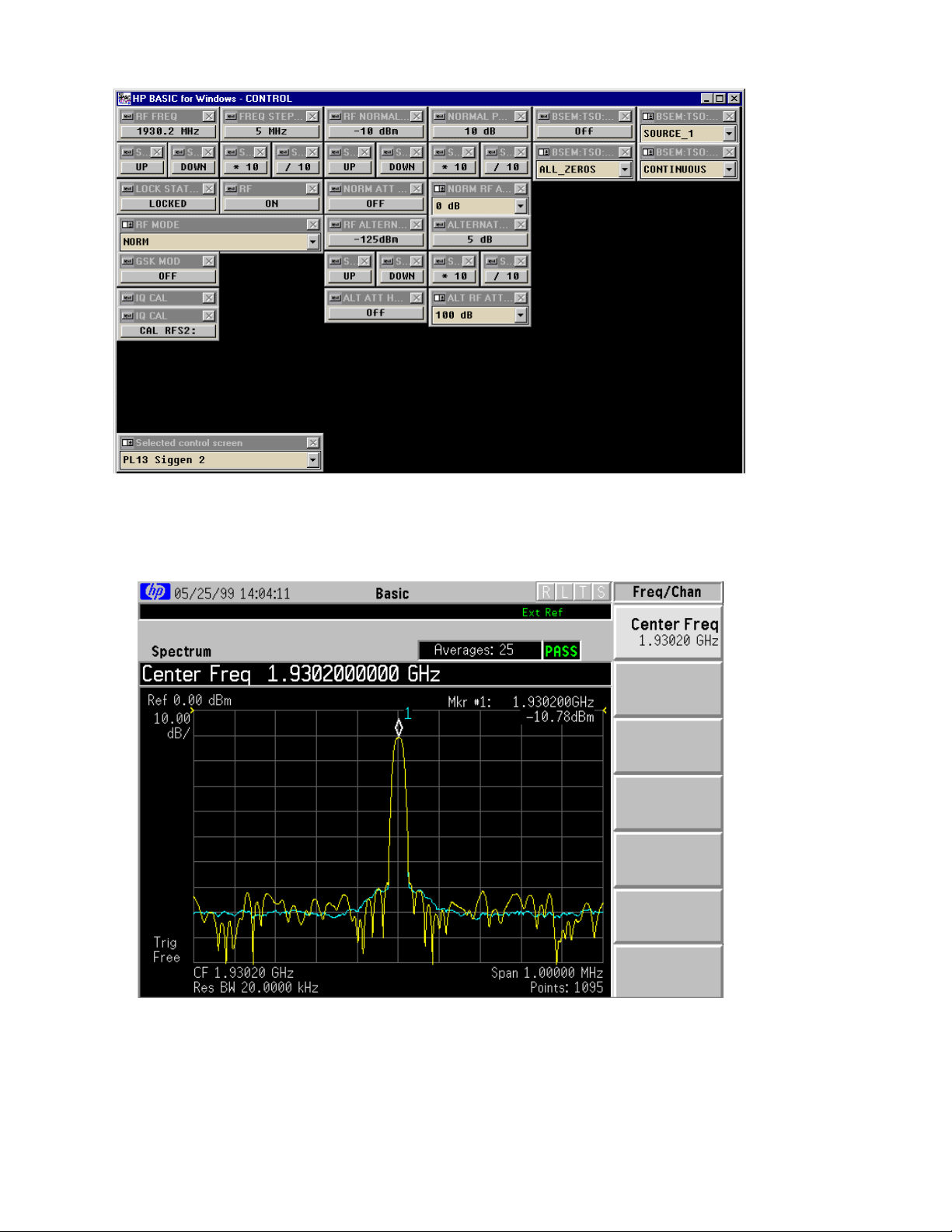
• Run the 8960 Control software on the Laptop (PC) and set the following:
• Selected control screen: PL13 Siggen 1 RF FREQ: 939 MHz
• RF NORMAL: -10 dBm NORMAL P…: 10 dB GSK MOD: OFF
Step the 8960 down in amplitude in 10 dB increments to -80 dBm.
Insure that each level step is accurate within ± 2 dB.
13

Operational Verification
Analog Generato r Level Accuracy, con t .
Verification
• Run the 8960 Control so ftware on the Laptop (PC) and set the
following:
• Selected control screen: PL13 Siggen 1 RF FREQ: 1.8052 GHz
• RF NORMAL: -10 dBm NORMAL P..: 10 dB
On the E4406A set Center Frequency t o 1.8052 GHz. Step the 8960 down i n
amplitude in 10 dB increments to -80 dBm. Insure that each leve l step is accurate
within ± 2 dB.
14

Operational Verification
•
Analog Generato r Level Accuracy, con t .
Verification
Run the 8960 Contro l software on the Laptop (PC) and set the followi n g:
Selected control screen: PL13 Siggen 1 RF FREQ: 1. 9302 GHz
RF NORMAL: -10 dBm NORMAL P..: 10 dB
On the E4406A set Center Frequency t o 1.9302 GHz. Step the 8960 down i n
amplitude in 10 dB increments to -80 dBm. Insure that each leve l step is accurate
within ± 2 dB.
Turn RF: OFF Before proceeding to SigGen 2 Tests
15

Operational Verification
Analog Generato r Level Accuracy, con t .
Verification
• RF must be OFF on SigGen 1 before proceeding with SigGen 2 testing.
• Run the 8960 Control software on the Laptop (PC) and set the following:
• Selected control screen: PL13 Siggen 2 RF FREQ: 939 MHz RF: ON
• RF NORMAL: -10 dBm NORMAL P..: 10 dB RF Mode: Norm
On the E4406A set Center Frequency t o 939 MHz. Step th e 8960 down in
amplitude in 10 dB increments to -80 dBm. Insure that each leve l step is accurate
within ± 2 dB.
16

Analog Generato r Level Accuracy, con t .
Verification
Run the 8960 Contro l software on the Laptop (PC) and set the followi n g:
Selected control s creen: PL13 Siggen 2 RF FREQ: 1.8052 GHz RF: ON
RF NORMAL: -10 dBm RF Mode: NORM NORMAL P..: 10 dB
• On the E4406A set Center Frequency to 1.8052 GHz. Step the 8960 down in
amplitude in 10 dB increments to -80 dBm. Insure that each leve l step is
accurate within ± 2 dB.
17
Operational Verification
Analog Generato r Level Accuracy, con t .
Verification
• Run the 8960 Control software on the Laptop (PC) and set the following:
Selected control s creen: PL13 Siggen 2 RF FREQ: 1.9302 GHz RF: ON
• RF Mode: NORM RF NORMAL: -10 dBm NORMAL P..: 10 dB
On the E4406A set Center Frequency t o 1.9302 GHz. Step the 8960 down i n
amplitude in 10 dB increments to -80 dBm. Insure that each leve l step is accurate
within ± 2 dB.
18

• Operational Verification
• Analog Ge nerator Spectral
Purity
Analog Generator Spectral Purity is a test to insure tha t the 8960 has harmonics and
spurious signals within specification.The test is run by setti ng the 8960 to a carrier
frequency of 300 MHz and power level of -10 dBm. Harmonics and spurious are checked
at 450MHz, 600 MHz, 750 MHz, and 900 MHz. The expected limits ar e:
Spectral Purity Harmonics - ≤ -25 dBc
Sub-Harmonics - ≤ -40 dBc
Non-Harmonics - ≤ -55 dBc <1500 kHz
≤ -68 dBc >1500 kHz
The current oper ating firmware in the 8960 does not allow manual operatio n of amplitude
or frequency using incremental steps for either Sig Gen 1 or 2, a PC with controlling
software is required.
A Laptop (or PC) is connected to the GPIB port of the 8960. For manual control run
“ MoM Control” software. For automated control ru n the “8960Verify” and
“Generator T est” software.
Connect the 8960 RF In/Out Connector to the E4406A RF I nput.
Verification
On the 8960 perform the following set up functions:
1. Press the blue ‘SHIFT’ button and the ‘PRESET’ button (front panel buttons not
shown above).
2. Press the display ‘Operating Mode’ button and set mode to Test using the knob.
3. Press the display ‘Test Function’ button and set function to CW using the knob.
4. Press the ‘RF Gen Freq’ button and set frequency to 300 MHz using the number
keypad and the kn ob.
5. Press the ‘ RF Gen Power’ button and set power to -10 dBm using the number
keypad and the kn ob.
19

• Operational Verification
• Analog Generator Spectral Purity
Verification
On the E4406A, press the ‘Preset’ System button, press the ‘Mode’ Control
button and set to ‘Basic’ Mode.
ON the E4406A make the following settings: Center Freq: 300 MHz Span: 10 kHz
Press the ‘ZOOM’ button, the ‘Marker’ button, and the ‘Search’ button. Select
the ‘TRACE’ screen button and set the trace to Spectrum Average. The 8960
amplitude should equal -10 dBm ± 2 dB.
20

Operational Verification
•
Analog Generator Spectral Purity
Verification
On the E4406A set t h e center frequency to 450 MHz. Press the
‘AMPLITUDE’ button and set Ref Value to -50 dBm. The Sub-Harmonic
expected limit is: ≤ -50 dBm.
On the E4406A set Center Frequency t o 600 MHz. The Harmonic expected
limit is: ≤ -35 dBm
21

Operational Verification
Analog Generator Spectral Purity
Verification
• On the E4406A set the Center Frequency to 750 MHz. The Sub-
Harmonic expected limit is: ≤ -50 dBm
On the E4406A set the Center Frequency to 900 MHz. The Harmonic
expected limit is: ≤ -35 dBm .
22

Verification
Operational Verification
Audio Generator Accuracy
• The Audio Generator test checks to insure that the 8960 has an audio source
signal with reasonable performance of accuracy .
• The test is run by setting the 8960 in the audio generat or mode and looping
an audio signal from the Audio Out BNC connect or to the Audio In Hi BN C
connector to meas ure level accuracy of the audio output. The audio generator
expected limits are:
• Level Accuracy - ± 0.03V
• Fo r aut omated control run the “8960Verify” and “Generator Test”
software.
•
• Connect the 8960 Audio Out Connector to the Audio In Hi Co nnector
with a BNC cable .
Begin the test procedure by pressing the blue ‘SHIFT’ button and RESET.
23

Operational Verification
Audio Generator Accur acy,cont.
Verification
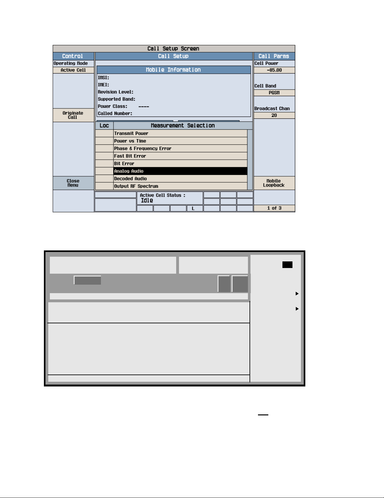
• Press the Instrument Select Button. Press the knob and act ivate
the Audio G enerator screen
Set audio amplitude to 1.414 V. Set audio frequency to 1 kHz.
24

Operational Verification
Audio Generator Accur acy,cont.
Verification
Press the ‘Measurement Selectio n’ button . Use the knob and select
Analog Audio, push the knob to start selection.
• The Analog Audi o measurement screen should appear. The
expected limits are: Level Accuracy: ± 0.03V
•
25

• Operational Verification
• GSM Generator Ampl itude Flatness, Peak Phase
Error,
Verification
GSM Generator tests check to insure that the 8960 has a GSM Digital signal within a
reasonable specification.The test is run by setting the 8960 to a traffic channel of 30 and
power level of -10 dBm. The E4406A is then s et in a digital measurement mode and
checks the 8960 GSM signal for Amplitude Flatness (PVT), Peak Phase Erro r, RMS Phase
Error, and Frequency Error. The expected limits are:
Amplitude Flatness - < ± .6 dBm
Peak Phase Error - < ± 8 degrees in PGSM & EGSM Bands
< ± 12 degrees in DCS and PCS Bands
RMS Phase Error - < ± 2 degree in PGSM and EGSM Bands
Frequency Error - < ± .04 ppm + TB
For automated control run the “8960Verify” and “Generator Test” software.Connect
the 8960 RF In/Out Connector to the E4406A RF Input.
• RMS Phase Error, and Frequency Error
On the 8960 perform the following set up functions:
1. Press the blue ‘SHIFT’ button and the ‘PRESET’ button (front panel buttons not
shown above).
2. Press the display ‘Operating Mode’ button and set mode to T est using the knob.
3. Press the display ‘Test Function’ button and set function to CW using the knob.
4. Press the ‘Broadcast Chan’ button and set the channel to 1 using the number
keypad and the kn ob.
5. Press the ‘ Cell Power’ button and set power to -10 dBm using the number
keypad and the kn ob.
26
Operational Verification
GSM Generator Am plitude Flatness, Peak Phase Error,
RMS Phase Error , and Frequen cy Error, cont.
Verification
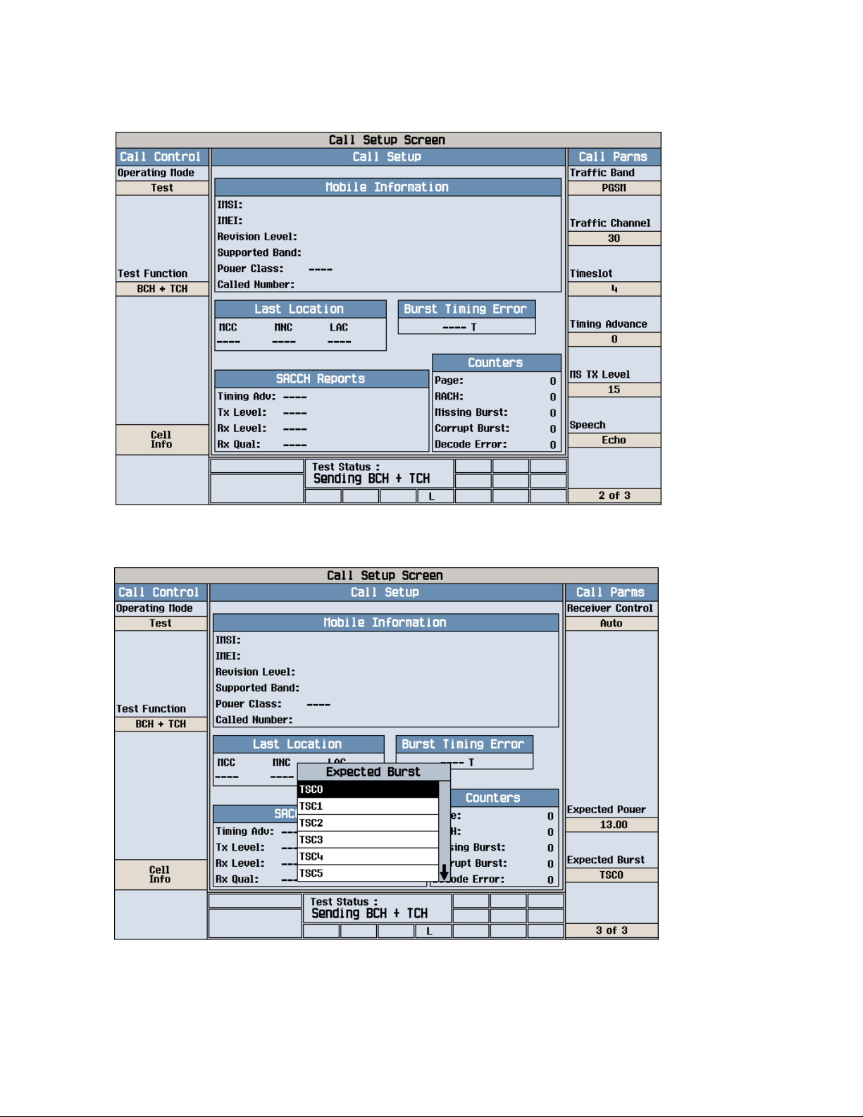
• Got to Screen 2 of 3. Set the Traffic Channel to 124 .
Go to Screen 3 of 3. Set the expected burst to TSC0.
27
Operational Verification
•
GSM Generator Am plitude Flatness, Peak Phase Error,
RMS Phase Error , and Frequen cy Error, cont.
Verification
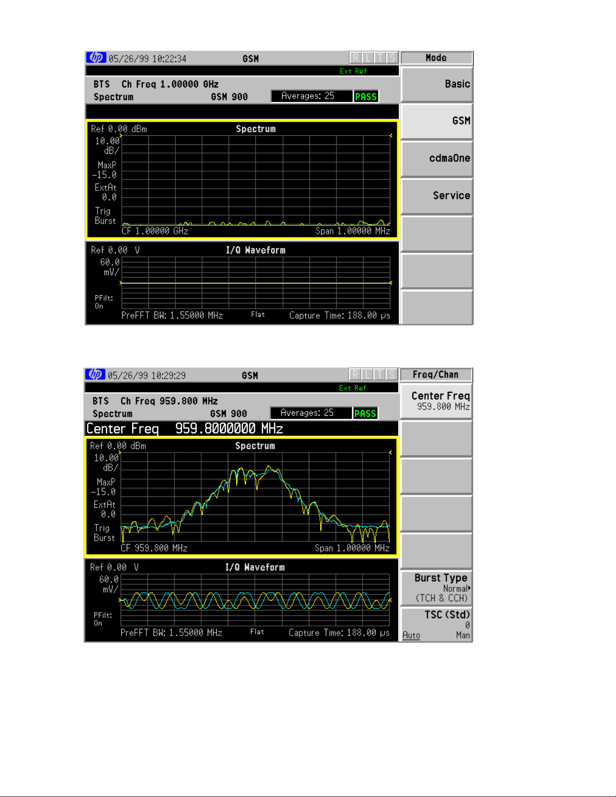
On the E4406A, press the ‘MODE’ Control button and set Mode field to GSM.
On the E4406A set the Center Frequency to 959.8 MHz (channel 124). The
Burst RF Spectrum should appear.
28

Operational Verification
GSM Generator Am plitude Flatness, Peak Phase Error,
RMS Phase Error , and Frequen cy Error, cont.
Verification
On the E4406A, press the PVTbut ton.
• On the E4406A, press the ‘AMPLITUDE’ Control butto n. Set ‘Scale/Div’
field to be .3 dB and the ‘Ref Value’ field to be -9 dBm. The display shown
above should appear. The expected PVT limits are: <± .6 dB flatness
29

Operational Verification
GSM Generator Am plitude Flatness, Peak Phase Error,
RMS Phase Error , and Frequen cy Error, cont.
Verification
On the E4406A, press the ‘Phase & Freq ’ button. The display shown
above should appear. The expected limits for Phase & Frequency are:
Peak Phase Error - <± 4 Degrees in PGSM & EGSM Bands
<± 6 Degrees in DCS and PCS Bands
RMS Phase Error - <± 2 Degrees in PGSM & EGSM Bands
Frequency Error - <± .04 ppm (18 Hz)
30

Operational Verification
Analog Audio Analyzer
The Analog Audio Analyz er is tested to insur e that the 8960
can accurately measure an audio signal within a reasonable limit.
The test is run by setting the 8960 into the Audio Analyzer measurement
mode. The E4433B is then set to output an Audio signal on the LF Out co nnector
at 1.414 Vp at a frequency of 1 kHz. The Analog Audio Measurement Accuracy
expected limit is:
Levels 10mv to 20V Peak - ± 0.04V
Frequency 200 Hz to 8 kHz
For automated control run th e “8960Verify” an d “Analyzer T est”
software.
Connect a BNC cable between the E4433B LF Out connector an d the
8960 Audio In Hi connector.
Verification
• Begin the test procedure by pressing the blue ‘SHIFT’ button and
RESET.
31
Operational Verification
Analog Audio Analyzer, cont.
Verification
Press the ‘Measurement Selectio n’ button . Use the knob and select
Analog Audio, push the knob to start selection.
FREQUENCY AMPLITUDE
4.000 000 000 00
EXT REF
GHz
-135.0
dBm
MOD
RF
Off
ON
Off
LF Out Amplitude
LF Out Source
(Func Gen)
LF Out Waveform
Modulation Status Information
MOD
LF Out
STATE DEPTH/DEV
On 1.414 Vp FuncGen 1.0000 kHz Sine
SOURCE
RATE WAVEFORM
LF Out Freq
1.0000 kHz
LF Out Period
LF Out Width
LF Out
On
1.414V
(Sine)
(N/A)
(N/A)
• On the E4433B press the LF Out button. Set LF Out to On. Set LF
Amplitude to 1.414Vp. Set the LF Out Frequency to be 1.0000 kHz.
32
Operational Verification
Analog Audio Analyzer, cont.
Verification
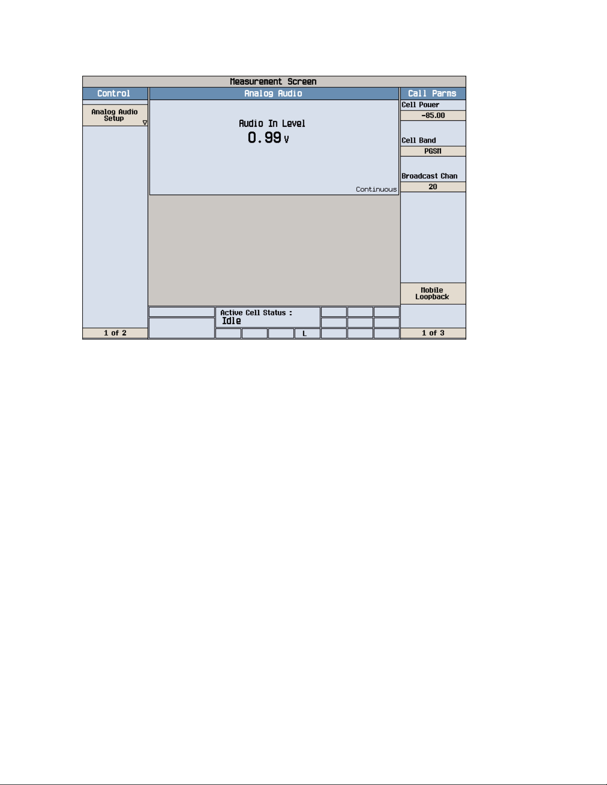
• The 8960 Analog Audio screen should display a voltage level
measurement of the audio signal from the E4433B .
• The Analog Audio measurement expected limit is ± 0.04V
33

Operational Verification
Analog Audio Analyzer, cont.
Verification
• The 8960 Analog Audio screen should display a voltage level
measurement of the audio signal from the E4433B .
• The Analog Audio measurement expected limit is ± 0.04V
34

Operational Verification
Analog Analyzer RF Power Meter, cont.
Verification
On the 8960 perform the following set up functions:
1. Press the blue ‘SHIFT’ button and the ‘PRESET’ button (front panel buttons not
shown above).
2. Press the display ‘Operating Mode’ button and set mode to Test using the knob.
3. Press the display ‘Test Function’ button and set function to CW using the knob.
Press ‘Measurement Selection’ button and select ‘Transmit Power’ as the
Operating Mode.
35
Operational Verification
Analog Analyzer RF Power Meter, cont.
Verification
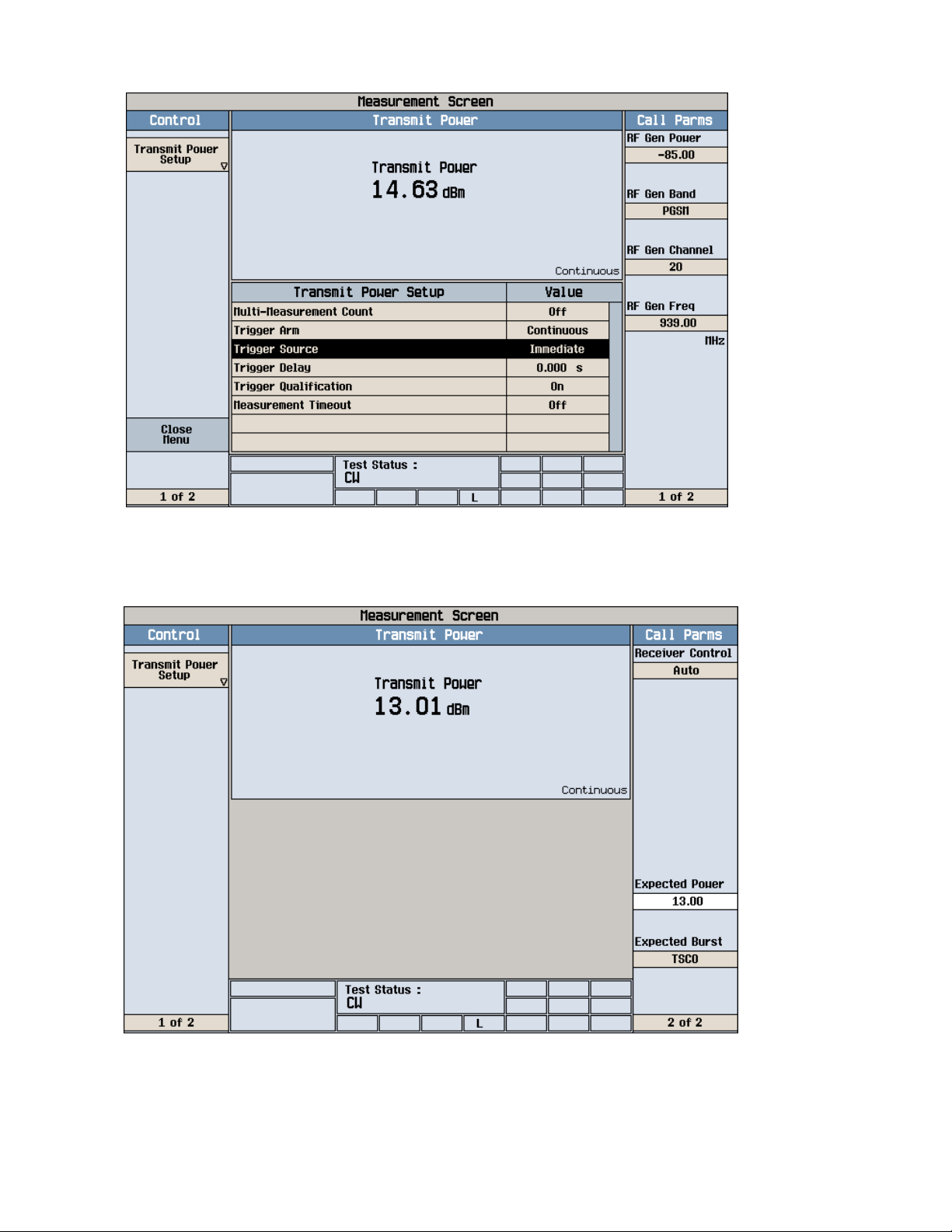
• Press ‘Transmit Power Setup’ button and set Trigger Source to
‘Immediate’.
On screen 2 of 2 set Expected Power to +13.00 dBm. RF Power
measurement Specification is < ± 1.63 dB.
36
Operational Verification
Analog Analyzer RF Power Meter, cont.
FREQUENCY AMPLITUDE
939.000 000 00
EXT REF
MHz
-15.00
dBm
MOD
RF
ON
Verification
ON
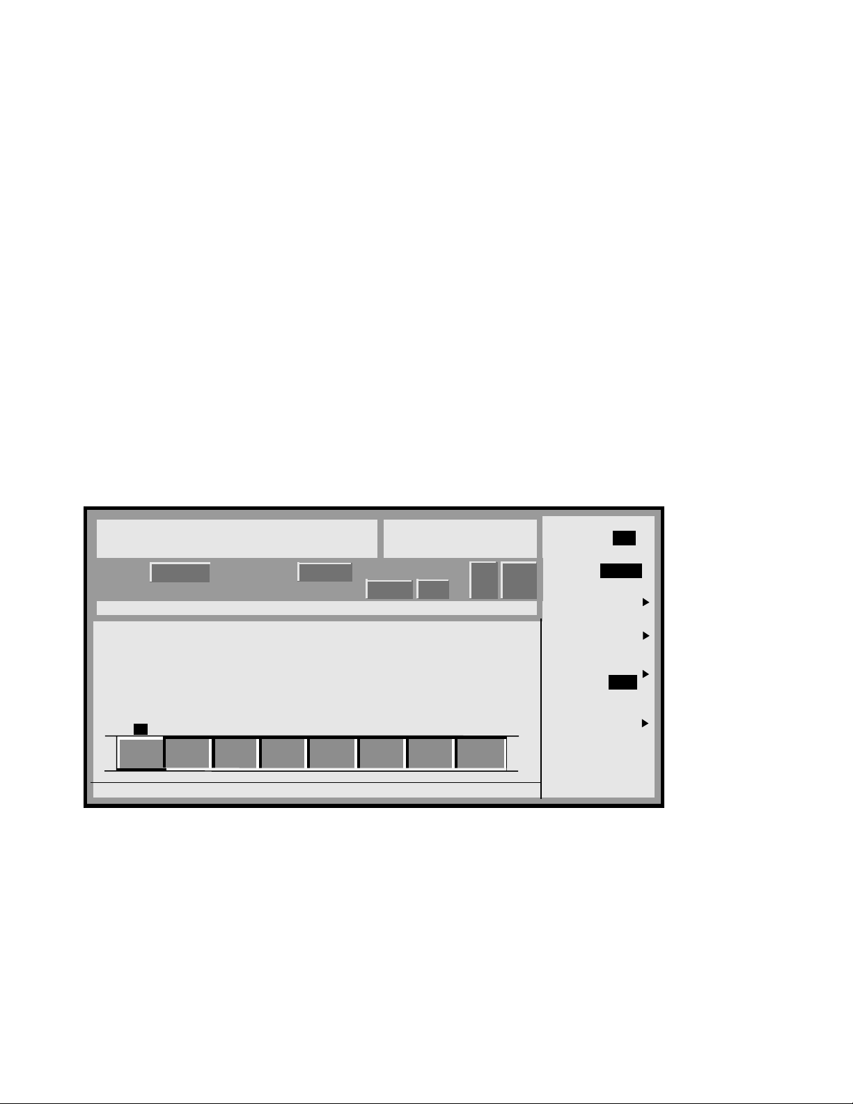
• On the E4433B set the Am plitude to -15 dBm.
On the 8960 set Expected Power to -15.00 dBm.
RF Power measurement expected limit is < ± 1.60 dB.
37

Operational Verification
Analog Analyzer RF Power Meter, cont.
FREQUENCY AMPLITUDE
1.850 000 000 00
EXT REF
GHz
13.00
dBm
MOD
RF
ON
ON
Change the E4433B amplitude to +13 dBm and frequency to 1.85 GHz .
• On screen 2 of 2 of the 8960 set expected power to +13.00 dBm.
• RF Power measurement expected limit is < ± 1.60 dB.
38
Operational Verification
GSM Analyzer
The GSM Analyzer is tes ted to insure that the 8960
can accurately measure a GSM burst signal within a reasonable limit.
The test is run by setting the 8960 into GSM Analyzer manual
measurement mode. The ESG D4000 is then set to output a GSM burst signal at
+15 dBm amplitude. The GSM Analyzer Measurement Accuracy expected limits
are:
Frequency Error
Measurement Accy. - < ± 24 Hz + Time Base
Residual Phase Error
Measurement Accy RMS - < ± 2 Degree
Measurement Accy. Peak - < ± 8 Degrees
Power versus Time
Rel. Measurement Accy at Time Offset - ± 2 dB
ORFS
Rel. Measurement Accy Freq. Offset - ± 3 dB
Verification
For automated control run th e “8960Verify” an d “Analyzer T est” software.
FREQUENCY AMPLITUDE
GSM
On
939.000 000 00
EXT REF
Data Format: Framed
Mod Type: MSK
GSM: STANDARD
Nxt Frame: Primary
MHz
GSM
Bits/Symbol: 1
SymRate: 270.8333ksps
Filter: 0.300 Gaussian
Chan: P-GSMBase 1
I/Q Scaling: 100%
13.00
ENVLP
I/
Q
Data: PN23
Repeat: Cont
0Pol: Normal
Diff Encode: On
GSM Timeslot Pattern
0
On
Normal
1
Off
Custom
2
Off
34567
Off
Off
CustomCustomCustom
Off
Custom
Off
Custom
dBm
RF
ON
Off
Custom
MOD
ON
Pattern
Frame Repeat
Frame Trigger
GSM
Off
Data Format
Framed
Configure
Timeslots
(N/A)
Single
Cont
(N/A)
More
(1 of 2)
On
Data
Begin by conn ecting a cable between the RFOut po rt of the ESG D4000 an d the RF
In/Out port of the 8960. Set the ESG D4000 to output a signal at a frequency of 939
MHz, GSM On, Burst On or Framed Data, and amplitude +13 dBm
39

Operational Verification
GSM Analyzer
Verification
On the 8960 perform the following set up functions:
1. Press the blue ‘SHIFT’ button and the ‘PRESET’ button (front panel buttons not
shown above).
2. Press the display ‘Operating Mode’ button and set mode to Test using the knob.
Select screen 3 of 3. Set ‘Receiver Control’ field to Manual. Set ‘Manual Freq’
to 939 MHz. Set ‘Expected Power’ to +13 dBm. Set ‘Expected burst to TSC0.
40
Operational Verification
GSM Analyzer, cont.
Verification
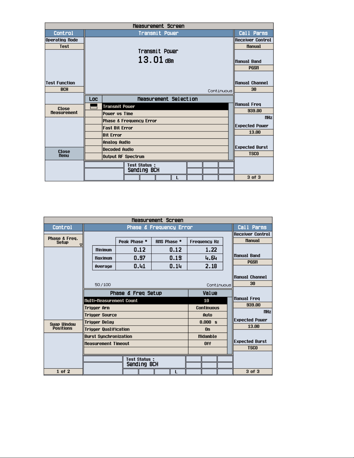
Press ‘Measurement Selection’ button and select ‘Transmit Power’ as
the Operating Mode. Transmit Power window should display a reading
of approximately +13 dBm
Press ‘Measurement Selection’ button and select ‘Phase & Frequency Error’ as
the Operating Mode. Press ‘Phase & Frequency Setup’ button. Select MultiMeasurement Count val ue to be 10. Close Menu to turn off the Setup window.
41

Operational Verification
GSM Analyzer, cont.
Verification
The Phase and Frequency Error window sh ould appear and display
average readings of Peak and RMSPphase error and Frequ ency error.
The expected measurement limits are:
Peak error is <± 8 Deg, RMS error is <±2 Deg, Frequency er ror is <±24 Hz.
Press ‘Measurement Selection’ button and select ‘Power vs. Time’ as the Operating
Mode. Press the ‘ Power vs. Time Setup’ button and then the ‘Measurem ent Setup’
button, set the Multi-Measurement Count value to be 10. Close menu to turn off
measurement setup window.
42

Operational Verification
GSM Analyzer, cont.
Verification
Press ‘Return to PvT Control’ button then press the ‘Change View’ button.
Press the ‘Numeric 1 of 2’ button. The Power vs Time Numeric Screen
1 should appear. The expected limits are:
0 usec - 0dBc ±2dBc -10 usec - ≤ 8dBc
43
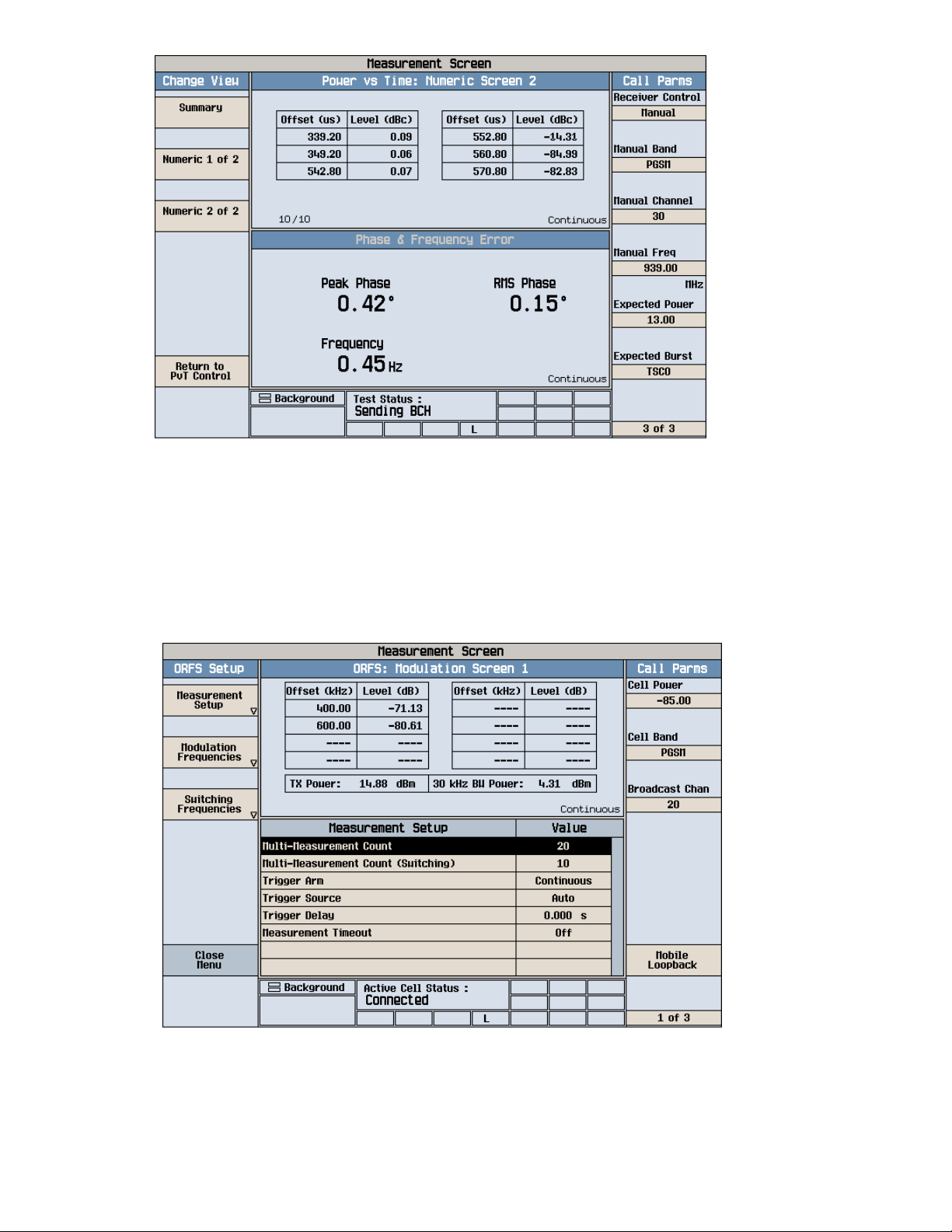
Operational Verification
GSM Analyzer, cont.
Press the ‘Numeric 2 of 2’ button. The Power vs Time Numeric Screen 2 should
appear. The expected limits are: 542.8usec - 0dBc ±2dBc 552.8usec - ≤ 8 dBc
Verification
Note on measured values: Power ver sus Time measurements are depend on the
accuracy of the s ource being measured. In the example above the E4433B had
performance of -14 dBc at a 552.8 usec offset on t he burst. Variation in burst timing
can vary the offset in dBc greatly. This measurement is meant to show consistency
between 8960 units using the same identical source for each unit tested.
Press ‘Measurement Selection’ button and select ‘Output RF Spectrum’ as the
Operating Mode. Press the ‘ORFS Setup’ and then the ‘Measurement Setup’
button. Set Multi- Measurement Count value to 20. Close menu to turn off window.
44
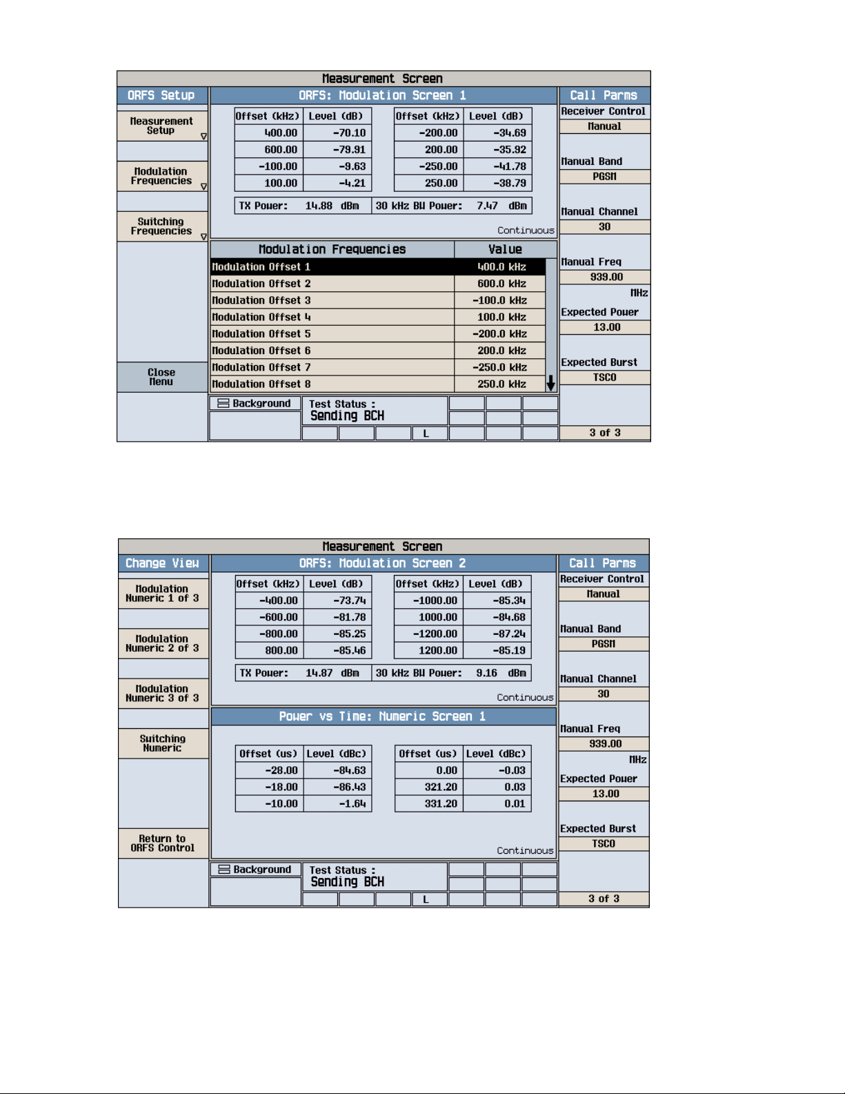
Operational Verification
GSM Analyzer, cont.
Verification
The ORFS measurement screen must be configured for offset frequency values
to make a measureme nt. Press the ‘Modulation Frequencies’ b utton. Load the
default frequencies into each offset by rotating t he knob to each offset and
pressing the ‘ON’ button. Load frequencies 100 kHz to 1200 kHz . Close the menu.
• Press ‘Return to ORFS Control’ button. Press ‘Chang e View’ button and select
which modulation numeric screens to view by pressing either t h e ‘Modulatio n
Numeric 1 of 3’ or the ’Modulation Numeric 2 of 3’ buttons..
45

46

Verification
Operational Verification
Call Processing with Phone
The Call Processing with a Phone test insures that the 8960 can originate, connect,
and measure calls to and from a GSM phone.
There are no specifications associated with this test. The test collects performance data
from the phone. If the same phone is used with each 8960 teste d the results should
match from unit to unit.
Currently the test is done in a manual mode a nd it is not feasible to collec t data from each
phone or unit tested. If the test is automated in the future it will be quite simple to collect
data from each phone or unit tested and then check for test consistency.
Begin by conn ecting the phone to the 8960. The p h one has an antenna
RF In/Out co nnector which must be connected to the 8960 RF In/Out
connector. The GSM phone should be suppli ed with the RF Interface cable.
• Begin the test procedure by pressing the blue ‘SHIFT’ button and
RESET.
47

Operational Verification
Call Processing with Phone, cont.
Verification
Do a Mobile Station Call Origination:
Select screen 2 of 3. On the phone enter several numbers and press the ‘Send’
or ‘Yes’ button.
• When a call is connected the test data should appear in the ‘Burst Timing Error’
window and in the ‘SACCH Reports’ window, the ‘Active Cell Status’ window
should say ‘Connected ’. Disconnect the call by pressing the ‘End Call’ button on
either the phone or th e 8960.
48

Operational Verification
Call Processing with Phone, cont.
Verification
• Do a Base Station Call Origination:
• Select screen 2 of 3. On the 8960 press the ‘Originate Call’ button. The phone
should ring, then press the ‘Send’ or ‘Yes’ button on the phone to connect the
call.
When a call is connected the test data should appear in the ‘Burst Timing Error’
window and in the ‘SACCH Reports’ window, the ‘Active Cell Status’ window should
say ‘Connected’ . Do not disconn ect, proceed to the next tests.
49

Operational Verification
Call Processing with Phone, cont.
Verification
• The 8960 and phone call connection must be tested for the followi ng
protocol steps:
• Traffic Channel Handover - Press the ‘Traffic Channel’ button
on the 8960. I n sure that the channel number can b e changed and the
call remains connected.
• Mobile Transmit Level Handover - Press the ‘MS TX Level’
button on the 8960. Insure that the transmit level can be set to a level
between 5 and 15 and the call remains connected. The TX Level Data in
the ‘SACCH Reports’ screen should change.
•
• Mobile Transmit Timing Advance Handover - Press the ‘Timing
Advance’ button on the 8960. Insure that the timing advance number
can be changed and the call remain s connected.
• Mobile Transmit Timeslot Handover- Press the ‘Timeslot’
button on the 8960. Insure that t he timeslot number can be set to a
timeslot between 3 and 5 and the call remains connected.
• Dual Band Handoff- Press the ‘Traffic Band’ button on the
8960. Insure that the the band can be changed from ‘PGSM’ to “DCS’
bands and the call remains connected.
• Press end call on either the phone or the 8960 to disconnect and stop
the test.
•
50
 Loading...