

HP 8924E CDMA Mobile Station Test Set
User’s Guide
Firmware Version A.02.00 and above
!
POWER
DO NOT APPLY
RF WHEN OFF
RF IN/OUT
MAX PWR
CDMA CALL CONTRO L
CDMA SCRNS
CELL
CALL
CTRL
SPECTRUM
GEN
CTRL
ANALOG SCRNS
ENCODER
RF
ANL
AF
ANL
SPEC ANL
RF
GEN
END
CALL
RANGE
RX
TEST
MSRPT
TX
TEST
DECODER
RX
TEST
ACP
TX
TEST
SCOPE
DUPLEX
CALL ANS
USER DATA
k1’
k1
k2’
k2
k3’
k3
ASSIGN
k4
RELEASE
k5
!
6 W
MAX PWR
200 mW
!
FUNCTIONS
MSG
PRINTER
HELP
PRINT
DATA FUNCTIONS
REF SET
METER
INCR
INCR
: 10
SET
LO LIMIT HI LIMIT
CURSOR
CONTROL
CANCELSHIFT
I/O CONFIG CONFIG
PREV TESTS
AVG
INCR X10
PUSH TO
SELECT
ANTENNA INDUPLEX OUT
INSTRUMENT STATE
ADRS
SAVE
LOCAL
RECALL
789
456
123
+
0
YES
ON/OFF
Ω
NO
%
ppm
dBµV
W
AUDIO OUTSQUELCHVOLUMEMIC/ACC
MAX
!
12 v Pk
_
HOLD
MEAS
RESET
ENTER
dB
GHz
dBm
%
MHz
V
s
kHz
mV
ms
Hz
µV
AUDIO IN
MAX
!
42 v Pk
PRESET
MEMOR
Y CARD
LOHI
HP Part No. 08924-90057
Printed in U. S. A.
October 1998
Rev. C
1

Copyright © Hewlett-Packard Company 1998
Notice Information contained in this document is subject to change without notice.
All Rights Reserved. Reproduct ion, adaptation, or translati on without prior written
permission is prohibited, except as allowed under the copyright laws.
This material may be reproduced by or for the U.S. Government pursuant to the
Copyright License under the clause at DFARS 52.227-7013 (APR 1988).
Hewlett-Packard Company
Learning Products Department
24001 E. Mission
Liberty Lake, WA 99019-9599
U.S.A.
2

Manufacturer’s Declaration
This statement is provided to c omply with the req uiremen ts of t he German So und
Emission Directive, from 18 January 1991.
This product has a sound pressure emission (at the operator position) < 70 dB(A).
• Sound Pressure Lp < 70 dB(A).
• At Operator Position.
• Normal Operation.
• According to ISO 7779:1988/EN 27779:1991 (Type Test).
Herstellerbescheinigung
Diese Information steht im Zusammenhang mit den Anforderungen der
Maschinenlärminformationsverordnung vom 18 Januar 1991.
• Schalldruckpegel Lp < 70 dB(A).
• Am Arbeitsplatz.
• Normaler Betrieb.
• Nach ISO 7779:1988/EN 27779:1991 (Typprüfung).
3

Safety
Considerations
GENERAL
This product and related document ation must be revi ewed for familiariz ation with
safety markings and instructions before operation.
This product has been designed and tested in accordance with IEC Publication
1010, "Safety Requirements for Electronic Measuring Apparatus," and has been
supplied in a s af e condition. This ins tr uction documentati on contains information
and warnings which must be followed by the user to ensure safe operation and to
maintain the product in a safe condition.
SAFETY EARTH GROUND
A uninterruptible safety earth ground must be provided from the main power
source to the product input wiring terminals, power cord, or supplied power cord
set.
CHASSIS GROUND TERMINAL
To prevent a potential shoc k hazard, always co nnect the rear-pa nel chassis gr ound
terminal to earth ground when operating this instrument from a dc power source.
SAFETY SYMBOLS
Indicates instrument damage can occur if indicated operating limits are exceeded.
!
Indicates hazardous voltages.
Indicates earth (ground) terminal
WARNING
A WARNING note denotes a hazard. It calls attention to a procedure,
practice, or the like, which, if not correctly performed or adhered to, could
result in personal injury. Do not proceed beyond a WARNING sign until the
indicated conditions are fully understood and met.
CAUTION
A CAUTION note denotes a hazard. It calls attention to an operation procedure,
practice, or the like, which, if not correctly performed or adhered to, cou ld resu lt
in damage to or destruction of part or all of the product. Do not proceed beyond
an CAUTION note until the indicated conditions are fully unde rstood and met.
4

Safety Considerations for this Instrument
WARNING This product is a Safety Class I instrument (provided with a protective
earthing ground incorporated in the power cord). The mains plug shall only
be inserted in a socket outlet provided with a protective earth contact. Any
interruption of the protective conductor inside or outside of the p roduct is
likely to make the product dangerous. Intentional interruption is
prohibited..
Whenever it is likely that the protection has been impaired, the instrument
must be made inoperative and be secured against any unintended operation.
If this instrument is to be energized via an autotransformer (for voltage
reduction), make sure the common terminal is connected to the earth
terminal of the power source.
If this product is not used as specified, the protection provided by the
equipment could be impaired. This product must be used in a normal
condition (in which all means for protection are intact) only.
No operator serviceable parts in this product. Refer servicing to qualified
personnel. To prevent electrical shock, do not remove covers.
Servicing instructions are for use by qualified personnel only. To avoid
electrical shock, do not perform any servicing unless you are qualified to do
so.
The opening of covers or removal of parts is likely to expose dangerous
voltages. Disconnect the product from all voltage sources while it is being
opened.
Adjustmen ts describe d i n t h e ma nu al are perfor me d w i t h po w e r su p pl i e d t o
the instrument while protective covers are removed. Energy available at
many points may, if contacted, result in personal injury.
The power cord is connected to internal capacitors that my remain live for
5 seconds after disconnecting the plug from its power supply.
For Continued protection against fire hazard, replace the line fuse(s) only
with 250 V fuse(s) or the same current rating and type (for example, normal
blow or time delay). Do not use repaired fuses or short circuited
fuseholders.
5

CAUTION: Always use the three-prong ac power cord supplied with this product. Failure to ensure
adequate earth grounding by not using this cord may cause product damage.
This product is designed for use in Installation Category II and Pollution Degree
2 per IEC 1010 and IEC 664 respectively.
This product has autorangi ng line voltage input, be sure the supply voltage is
within the specified range.
Ventilation Requirements: When installing the product in a cabinet, the
convection into and out of the product must not be restricted. The ambient
temperature (outside the cabinet) must be less than the maximum operating
temperature of the product by 4° C for every 100 watts dissipated in the cabinet.
If the total power dissipated in the cabin et is greater than 80 0 watts, then forced
convection must be used.
Product Markings CE - the CE mark is a registered trademark of the European Community. A CE
mark accompanied by a year indicated the year the design was proven.
CSA - the CSA mark is a registered trademark of the Canadian Standards
Association.
6

HP 8924E
Hewett-Packard Warranty Statement for Commercial Products
Duration of
Warranty: 1 year
1. HP warrants HP hardware, accessories and supplies against defects in materials and
workmanship for the period specified above. If HP receives notice of such defects
during the warranty period, HP will, at its option, either repair or replace products
which prove to be defective. Replacement products may be either new or like-new.
2. HP warrants that HP software will not fail to execute its programming instructions, for
the period specified above, due to defects in material and workmanship when p roperly
installed and used. If HP receives notice of such defects during the warranty period, HP
will replace software media which does not execute its programming instructions due
to such defects.
3. HP does not warrant that the operation of HP products will be uninterrupted or error
free. If HP is unable, within a reasonable time, to repair or replace any product to a
condition as warranted, customer will be entitled to a refund of the purchase price upon
prompt return of the product.
4. HP products may contain remanufactured parts equivalent to new in performance or
may have been subject to incidental use.
5. The warranty p eriod begins on the date of delivery or on the date of installation if
installed by HP. If customer schedules or delays HP installation more than 30 days after
delivery, warranty begins on the 31st day from delivery.
6. Warranty does not apply to defects resulting from (a) improper or inadequate mainte-
nance or calibration, (b) software, interfacing, parts or supplies not supplied by HP, (c)
unauthorized modification or misuse, (d) operation outside of the published environmental specifications for the product, or (e) improper site preparation or maintenance.
7. TO THE EXTENT ALLOWED BY LOCAL LAW, THE ABOVE WARRANTIES
ARE EXCLUSIVE AND NO OTHER WARRANTYOR CONDITION, WHETHER
WRITTEN OR ORAL IS EXPRESSED OR IMPLIED AND HP SPECIFICALLY
DISCLAIMS ANY IMPLIED WARRANTIES OR CONDITIONS OR MERCHANTABILITY, SATISFACTORY QUALITY, AND FITNESS FOR A PARTICULAR
PURPOSE.
8. HP will be liable for damage to tangible property per incident u p to the greater of
$300,000 or the actual am ount paid f or th e product t hat is the subject of th e claim, an d
for damages for bodily injury or death, to the extent that all such damages are determined by a court of competent jurisdiction to have b een directly caused b y a defective
HP product.
7

9. TO THE EXTENT ALLOWED BY LOCAL LAW, THE REMEDIES IN THIS
WARRANTY STATEMENT ARE CUSTOMER’S SOLE AND EXCLUSIVE
REMEDIES. EXCEPT AS INDICATED ABOVE, IN NO EVENT WILL HP OR ITS
SUPPLIERS BE LIABLE FOR LOSS OF DATA OR FOR DIRECT, SPECIAL,
INCIDENTAL, CONSEQUENTIAL (INCLUDING LOST PROFIT OR DATA), OR
OTHER DAMAGE, WHETHER BASED IN CONTRACT, TORT, OR
OTHERWISE.
FOR CONSUMER TRANSACTIONS IN AUSTRALIA AND NEW ZEALAND:
THE WARRANTY TERMS CONTAINED IN THIS STATEMENT, EXCEPT TO
THE EXTENT LAWFULLY PERMITTED, DO NOT EXCLUDE RESTRICT OR
MODIFY AND ARE IN ADDITION TO THE MANDATORY STATUTORY
RIGHTS APPLICABLE TO THE SALE OF THIS PRODUCT TO YOU.
8

HP 8924E Support
Contacts
Repair assistance is available for the HP 8924E CDMA Mobile Test Set from the factory
by phone and e-mail. Internal Hewlett-Packard users can contact the factory through
HPDesk or cc:Mail© (Lotus Corporation). Parts information is also available from
Hewlett-Packard.
When calling or writing for repair assistance, please have the fo llowing information
ready:
• Instrument model number (HP 8924E)
• Instrument Serial Number (tag located on the rear panel).
• Installed options - if any (tag located on the rear panel).
• Instrument firmware revision (displayed at the top of the screen when the Test Set is
powered up, and is also displayed on the CONFIGURE screen).
Support Telephone
1 800 827 3848 (Spokane Division Service Assistance, U.S. only)
1 509 921 3848 (Spokane Division Service Assistance, International)
1 800 227 8164 (HP Direct Parts Ordering, U.S. only)
1 916 783 0804 (HP Service Parts Identification, U.S. & Intl.)
Electronic mail (Internet): Spokane_Service@spk.hp.com
HP Desk: Spokane Service / HP1000/21
cc:Mail: SERVICE, SPOKANE /HP-Spokane,desk1
Numbers:
9

Table 1 Regional Sales and Service Offices
United States of America
U.S. Instrument Support Center
For Test & Measurement Equipment
Repair & Calibration.
Hewlett-Packard Company
Englewood, Colorado 80112
Telephone: (800) 403-0801
Fax: (888) 857-8161
South Eastern E urope
Sales and Service
Hewlett-Packard Ges. m.b.h.
Liebigasse 1
P.O. Box 72
A-1222 Vienna, Austria
Telephone: 43 222 2500 0
Telex: 13 4425
Asia
Sales and Service
Hewlett-Packard Asia Ltd.
22-30/F Pere gri n e T ow e r
Lippo Center
89 Queensway, Central
Hong Kong
G.P.O. Box 863 Hong Kong
United States of America
Customer Information Center
For Assistance On All HP
Products.
Hewlett-Packard Company
Tel: (800) 752-0900
6:00 am to 5:00 pm Pacific Time
Parts Direct: 1-800-227-8164
European Multicountry Region
Sales and Service
Hewlett-Packard S.A.
P.O. Box 95
150, Route dv Nant_dl_AVRIL
CH-1217 Meyrin 2
Geneva, Switzerland
Telephone: (41/22) 780-81 11
Fax: (41/22) 780-8542
Japan
Sales and Service
Hewlett-Packard Japan, Ltd.
3-29-21, Takaido-Higashi
Suginami-Ku, Tokyo 168-8585
Telephone: 81 3 3331-6111
Fax: 81 3 3331-6631
United Kingdom
Sales and Service
Hewlett-Packard Ltd.
Cain Road
Amen Corner
Bracknell, Berkshire
RG12 1HN
United Kingdom
Telephone: 44 344 360000
Fax: 44 344 363344
Northern Europe
Sales and Service
Hewlett-Packard Nederland B.V.
Startbaan 16
1187 XR
Amstelveen, The Netherlands
P.O. Box 667
Telephone: 31/20 5476911 X 6631
Fax: 31-20-6471825NL
International Sales Branch
Headquarters
Sales and Service
Hewlett-Packard S.A.
39 Rue Veyrot
P.O. Box 365
1217 Meyrin 1
Geneva, Switzerland
Telephone: 852-848-7777
Fax: 852-868-4997
Australia, New Zealand
Sales and Service
Hewlett-Packard Ltd.
P.O. Box 221
31-41 Joseph Street
Blackburn, Victoria 3130
Telephone: (61/3) 895-2895
Fax: (61/3) 898-9257
10
Canada
Sales and Service
Hewlett-Packard (Canada) Ltd.
5150 Spectrum Way
Mississauga, Ontario L4W 5G1
Canada
Telephone: (416) 206-4725
Fax: (416) 206-4739
Telephone: 41-22-780-4111
Fax: 41-22-780-4770
Canada
Service Center
Hewlett-Packard Company
17500 Transcanada Highway
S. Serv Road
Kirkland, Quebec H9J 2X8
Canada
Telephone: (416) 206-3295

Table 1 Regional Sales and Service Offices (Continued)
Canada
Service Center
Hewlett-Packard Ltd.
11120 178 Street
Edmonton, A lberta T5S 1P2
Canada
Telephone: (403) 486-6666
Fax: (403) 489-8764
Latin America
Hewlett-Packard Company
LAHQ Mexico City
Col. Lomas de Virreyes
11000 Mexico D.F.
Mexico
Telephone: (52/5) 326-4000
Fax: (52/5) 202 7718
11

In this Book Throughout this manual the term "Test Set" is used to denote the HP 8924E.
Test Set screens sh own in thi s ma nual may not match those display ed on the Test
Set in every detail.
Chapter 1, Getting Started
This chapter provides basic remote and front-panel operating procedures, a quick check
for verifying operation, HP-IB programming procedures, and simple programming
examples.
Chapter 2, Configuring Your Test Set
This chapter provides information about setting screen inten sity , setting RF voltage
interpretation, setting time and date, and setting the beeper’s volume.
Chapter 3, Operating Overview
This chapter explains how to specify units of measure, how to use the analog meter,
how to use measurement averaging, how to set a measurement reference, how to set
measurement limits, how to enter and change values, how to save and recall instrument
setups, how to use the USER keys, and how to set a frequency offset. It also descri bes
some important interactions that occur between screen settings.
Chapter 4, Keys
This chapter provides front-panel key descriptions.
Chapter 5, Connectors
This chapter describes the front and rear panel connectors.
Chapter 6, Screens
This chapter provides a picture of each screen available on the Test Set with an overview of the functions provided.
Chapter 6, Fields
This chapter provides a description of the functions performed by each field.
Chapter 7, Memory Cards, Mass Storage
This chapter describes memory cards and mass storage devices used with the
Test Set.
12

Error Messages
This section discusses error and operating messages.
13

14

Contents
1 Getting Started
Before Connecting a Radio 26
Accessing the Test Set’s Screens 27
Changing A Field’s Setting 30
Obtaining Measurement Results 34
Control Annunciators 35
Verifying th at the Test Set is Operating P roperly 36
15

Contents
2 Configuring Your Test Set
Recommended Calibration Procedures 40
Instrument Display Setup 42
16

Contents
Operating Overview
3
To Change the Measurement Display 45
To Enter and Change Values 51
Saving and Recalling Instrument Setups 54
Using USER Keys 59
Setting an RF Generator/Analyzer Frequency Offset 62
Setting an RF Generator/Analyzer Level Offset 63
Printing A Screen 64
Triggering Analog Measurements In Local Mode (Front Panel
Operation) 65
Triggering CDMA Measurements In Local Mode (Front Panel
Operation) 66
17

Contents
4 Description of Keys
Keys That Begin with the Letter A 69
Keys That Begin with the Letter C 70
Keys That Begin with the Letter E 71
Keys That Begin with the Letter H 72
Keys That Begin with the Letter I 73
Keys That Begin with the Letter K 74
Keys That Begin with the Letter L 75
Keys That Begin with the Letter M 76
Keys That Begin with the Letter O 77
Keys That Begin with the Letter P 78
Keys That Begin with the Letter R 79
Keys That Begin with the Letter S 80
Keys That Begin with the Letter Y 81
Keys That Begin with a Number 82
Symbol Keys 83
Miscellaneous Hardware 84
DATA FUNCTIONS Keys 85
USER Keys 86
18

Contents
5 Description of Connectors
Connectors That Begin with the Letter A 89
Connectors That Begin with the Letter C 92
Connectors That Begin with the Letter D 96
Connectors That Begin with the Letter E 97
Connectors That Begin with the Letter H 98
Connectors That Begin with the Letter M 99
Connectors That Begin with the Letter P 101
Connectors That Begin with the Letter R 103
Connectors That Begin with the Letter S 105
Connectors That Begin with a Number 107
19

Contents
6 Description of Screens
Analog Meas Screen 110
Authentication (Call Control) 112
Call Configure (Call Control) 113
Call Control Screen 114
Call Data (Call Control) 115
CDMA Call Control Screen 118
CDMA Cell Site Configuration Screen 119
CDMA Cellular Mobile Receiver Test Screen 120
CDMA Cellular Mobile Transmitter Test Screen 122
CDMA Generator Control Screen 123
CDMA Mobile Reporting Screen 125
CDMA Transmitter Power Range Test Screen 126
CDMA Reverse Channel Spectrum Screen 127
Configure Screen 128
I/O Configure Screen 129
Oscilloscope Screens 130
Print Configure Screen 131
Spectrum Analyzer Screens (Opt 012 only) 132
20

Contents
7 Description of Fields
Fields That Begin with the Letter A 136
Fields That Begin with the Letter B 156
Fields That Begin with the Letter C 159
Fields That Begin with the Letter D 172
Fields That Begin with the Letter E 187
Fields That Begin with the Letter F 194
Fields That Begin with the Letter G 199
Fields That Begin with the Letter H 200
Fields That Begin with the Letter I 202
Fields That Begin with the Letter L 207
Fields That Begin with the Letter M 208
Fields That Begin with the Letter N 220
Fields That Begin with the Letter O 227
Fields That Begin with the Letter P 231
Fields That Begin with the Letter R 241
Fields That Begin with the Letter S 258
Fields That Begin with the Letter T 268
Fields That Begin with the Letter U 279
Fields That Begin with the Letter V 281
21

Contents
Fields That Begin with the Letter W 283
Fields That Begin with a Number 284
22

Contents
8 Memory Card s/Mass Storage
Using Memory Cards 286
Backing Up Procedure and Library Files 292
Copying Files Using IBASIC Commands 293
Default File System 295
Mass Storage Device Overview 297
Mass Storage Access 306
DOS and LIF File System Considerations 307
Using the ROM Disk 311
Using RAM Disk 312
Using External Disk Drives 314
23

Contents
Index 347
24

1
Getting Started
This chapter will help familiarize you with fundamental Test Set operation,
including:
• Accessing screens and fields
• Making a simple measurement
• Preparation for remote operation via HP-IB
25

Chapter 1, Getting Started
Before Connecting a Radio
Before Connecting a Radio
NOTE: The RF IN/OUT port should be used for all transmitter tests when the radio is co nnected
directly to the Test Set. (All MSUT (Mobile Station Under Test) transmitter power
measurements are made through this port). Off-the-air measurements can be made using the
highly-sensitive ANT IN port.
CAUTION: Overpower Damage — Refer to the Test Set’s front panel for maximum input power level.
Exceeding this level can cause permanent instrument damage.
Other Damage — Blocking the fans’s rotation or operating the Test Set in an
environment that causes excessive heat may cause damage.
Important: If excessive temperatures are sensed on the power supply regulator
assembly, the Test Set’s power supply will shut off. After temperature has
lowered to within normal operating range, use the POWER switch to cycle power
on. Remove RF power from the RF IN/OUT connector whenever the Test Set is
off.
26

Accessing the Test Set’s Screens
CDMA and Analog Modes
The Test Set has two operating modes, analog and CDMA. In CDMA mode, the
Test Set configures its elf as a cali brate d CDMA ba se st ation. In Anal og mode, the
Test Set has AMPS, NAMPS and TACS analog cellular phone test capability.
CDMA is the default power-up mode. To enter analog mode from CDMA mode:
• press one of th e ANLG SCRNS key s, or
• select a screen from the Analog To Screen menu, or
• programmatically select an analog screen using the display (DISP) HP-IB subsystem,
or
• execute a CDMA to Analog handoff.
Chapter 1, Getting Started
Accessing the Test Set’s Screens
To enter CDMA mode from analog mode:
• press one of the CDMA SCRNS keys, or
• select a screen from the CDMA To Screen menu, or
• programmatically select a CDMA screen using the display (DISP) HP-IB subsystem.
27
Chapter 1, Getting Started
Accessing the Test Set’s Screens
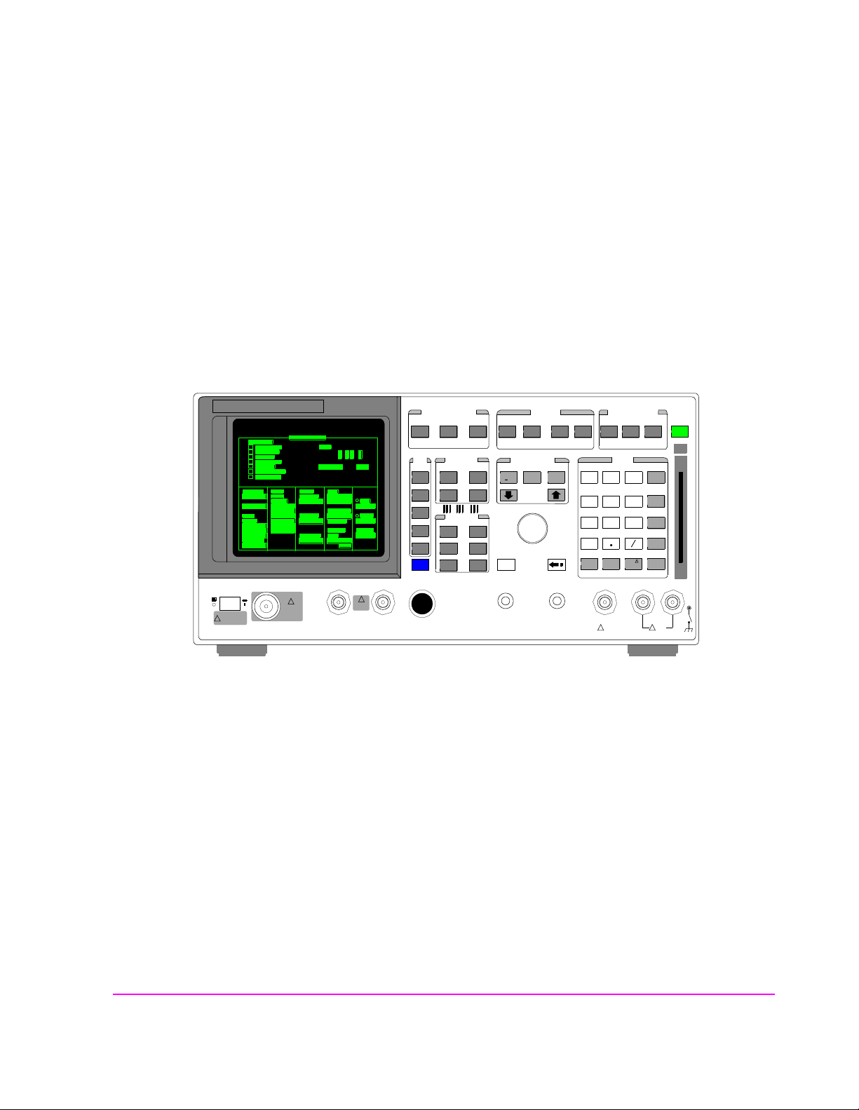
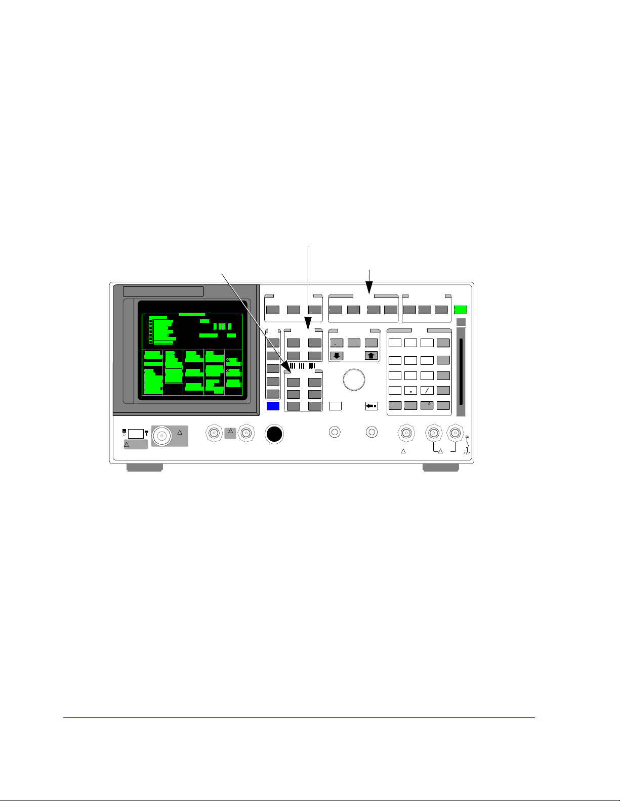
Functions Screens
Screens that control various instrument functions such as configuration, access to
the Tests subsystem, and the PREV (previous screen) key are found under the
front-panel “Functions” bracket.
CDMA Digital Transceiver Measurements
Analog Transceiver Tests
!
POWER
DO NOT APPLY
RF WHEN OFF
RF IN/OUT
MAX PWR
!
6 W
DUPLEX OUT
MAX PWR
200 mW
!
ANTENNA IN
Figure 1 Accessing Test Set Screens
Instrument Functions
CDMA CALL CONTRO L
CDMA SCRNS
CELL
CALL
CTRL
SPECTRUM
GEN
CTRL
ANALOG SCRNS
ENCODER
RF
ANL
AF
ANL
SPEC ANL
RF
GEN
END
CALL
RANGE
RX
TEST
MSRPT
TX
TEST
DECODER
RX
TEST
ACP
TX
TEST
SCOPE
DUPLEX
CALL ANS
USER DATA
k1’
k1
k2’
k2
k3’
k3
ASSIGN
k4
RELEASE
k5
FUNCTIONS
MSG
PRINTER
HELP
PRINT
DATA FUNCTIONS
REF SET
METER
INCR
INCR
: 10
SET
LO LIMIT HI LIMIT
CURSOR
CONTROL
CANCELSH IFT
I/O CONFIG CONFIG
PREV TESTS
AVG
INCR X10
PUSH TO
SELECT
INSTRUMENT STATE
ADRS
LOCAL
789
456
123
0
NO
YES
ppm
ON/OFF
W
AUDIO OUTSQUELCHVOLUMEMIC/ACC
MAX
!
12 v Pk
SAVE
RECALL
+
Ω
%
dBµV
_
HOLD
MEAS
RESET
ENTER
dB
GHz
dBm
%
MHz
V
s
kHz
mV
ms
Hz
µ
V
AUDIO IN
MAX
!
42 v Pk
PRESET
MEMOR
Y CARD
LOHI
28
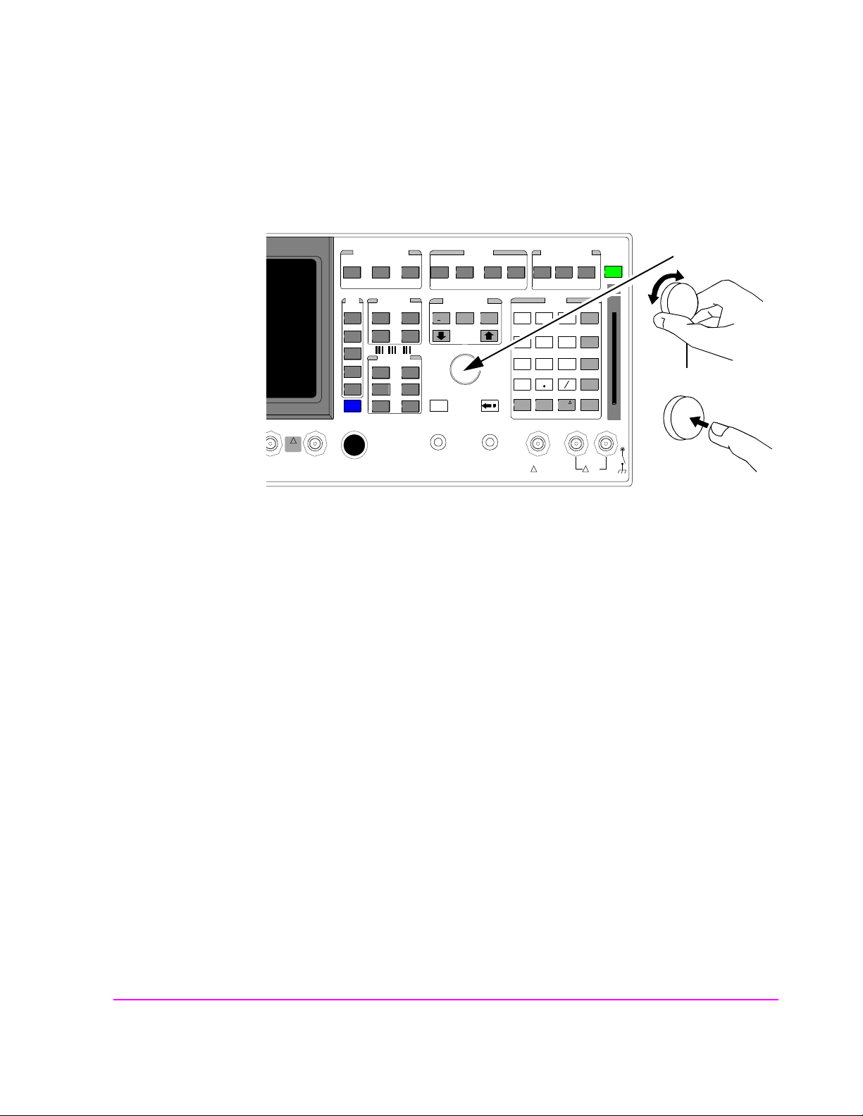
Cursor Control
Chapter 1, Getting Started
Accessing the Test Set’s Screens
INSTRUMENT STATE
ADRS
SAVE
LOCAL
RECALL
789
456
123
+
0
YES
ON/OFF
Ω
NO
%
ppm
dBµV
W
AUDIO OUTSQUELCHVOLUMEMIC/ACC
MAX
!
12 v Pk
_
HOLD
MEAS
RESET
ENTER
dB
GHz
dBm
%
MHz
V
s
kHz
mV
ms
Hz
µ
V
AUDIO IN
MAX
!
42 v Pk
PRESET
1
MEMOR
Y CARD
2
LOHI
MAX PWR
200 mW
!
ANTENNA IN
CDMA CALL CON TROL
CDMA SCRNS
CELL
CALL
CTRL
SPECTRUM
GEN
CTRL
CDMA SCRNS
ENCODER
RF
ANL
AF
ANL
SPEC ANL
RF
GEN
END
CALL
RANGE
RX
TEST
MSRPT
TX
TEST
DECODER
RX
TEST
ACP
TX
TEST
SCOPE
DUPLEX
CALL ANS
USER DATA
k1’
k1
k2’
k2
k3’
k3
ASSIGN
k4
RELEASE
k5
FUNCTIONS
MSG
PRINTER
HELP
PRINT
DATA FUNCTIONS
REF SET
METER
INCR
INCR
: 10
SET
LO LIMIT HI LIMIT
CURSOR
CONTROL
CANCELSHIFT
I/O CONFIG CONFIG
PREV TESTS
AVG
INCR X10
PUSH TO
SELECT
1. Position
To position the cursor, rotate the Cursor Control knob, which moves the cursor from
field to field or from menu item to menu item. Normally the cursor appears as a small
highlighted rectangular box.
2. Select
To select an item, push the Cursor Co ntrol knob . After selection, the background of the
item selected becomes highlighted or the item selected appears in an associated field.
29
Chapter 1, Getting Started
Changing A Field’s Setting
Changing A Field’s Setting
There are several types of CRT display fields in the Test Set. This section
describes some of the different types of fields, and how they are used.
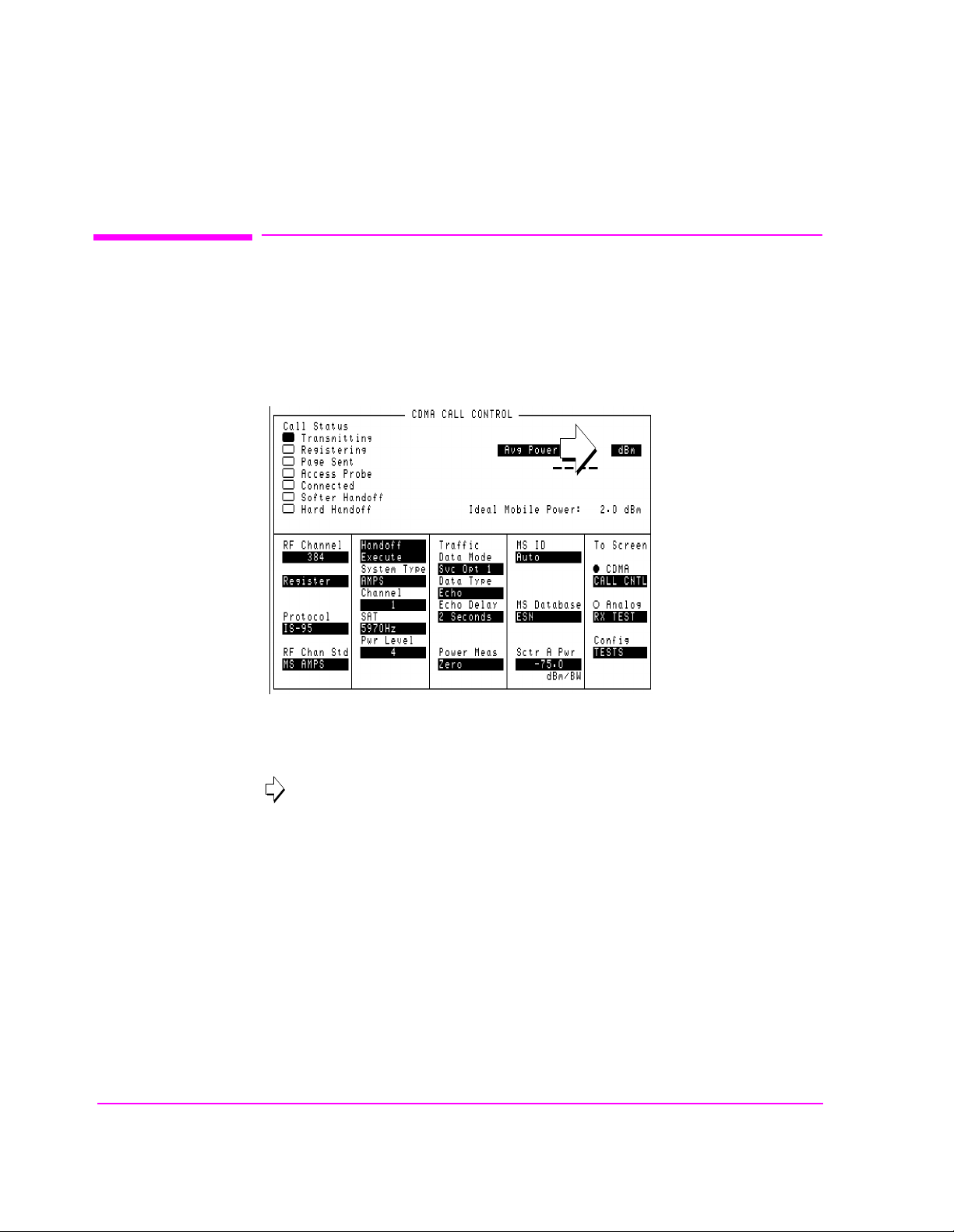
Units-of-Measure Field
Figure 2 Units-of-Measure Field
Units-of-measure fields allow selection of valid units for given measurement. See
figure 2 to see an example of a units-of-measure field.
in
To change a unit-of-measure
1. Position the cursor at the unit field on the display.
2. Press a key labeled with a different unit-of-measure (such as W).
3. If the new units are valid, the measurement valu e will be displayed in the new unit-of-
measure.
30

Underlined Immediate-Action Field
Chapter 1, Getting Started
Changing A Field’s Setting
Figure 3 Underlined Immediate-Action Field
Underlined immediate action fields provide a choice of two settings. See in
figure 3 to see an example of an underlined immediate-action field.
To change an underlined entry
1. Position the cursor at the field.
2. Push the CURSOR CONTROL knob or the ENTER key to underline the desired
choice.
31

Chapter 1, Getting Started
Changing A Field’s Setting
One-of-Many Field
Figure 4 One-of-Many Field
One-of-many fields displ ay a list of ch oic es when sel ected. See in figure 4 to
see an example of a one-of many field.
To make a one-of-many choice
1. Position the cursor at the field.
2. Push the C
3. Move the cursor through the choices by turning the knob.
4. Push the C
URSOR CONTROL knob or the ENTER key to display the choices.
URSOR CONTROL knob or the ENTER key to make the choice.
32

Numeric-Entry Field
Chapter 1, Getting Started
Changing A Field’s Setting
Figure 5 Numeric-Entry Field
Numeric-entry fields contain numeric values. See in figure 5 to see an
example of a numeric-entry field.
To change a value
1. Position the cursor at the field.
2. Key in the desired number using the DATA keys.
3. Press ENTER to select the choice.
OR
1. Position the cursor at the field.
2. Push the C
3. Turn the knob to increment or decrement the value.
4. Push the C
URSOR CONTROL knob to highlight the desired choice.
URSOR CONTROL knob or the ENTER key to select the choice.
33

Chapter 1, Getting Started
Obtaining Measurement Results
Obtaining Measurement Results
Setting Up a Call
To obtain CDMA measurements, the Test Set must have the MSUT (Mobile
Station Under Test) on a call (the Connected annunciator on the CDMA CALL
CONTROL screen is lit when the MSUT is on a call).
The procedure for setting up a call is provided in “Setting Up a Call”, found in the HP
8924E Introduction to Operation
performing CDMA tests.
Triggering and Displaying Measurements
. In this guide, there are also procedures for
When operate d over the front panel (loca l control), Tes t Set measurement results
are obtained by selecting a screen that displays the desired measurement, arming
the measurement if necessary, and observing the displayed value.
When operated remotely, measurement results are obtained via HP-IB by
triggering a measurement if necessary and querying the desired measurement
field.
NOTE: In CDMA mode, transmitter (TX) measu rements and rec eiver (RX) measur ements c an
run concurrently. For example, an Average Power or Channel Power measurement
can be queried while the RX TEST screen is selected and an FER measurement is
running.
For a detailed description of triggering measurements, see
Displaying Measurements" on page 34
.
"Triggering and
34

Control Annunciators
The letters and symbols at the top right corner of the display indicate these conditions:
R indicates the Test Set is in remote mode. The Test Set can be put into the remote mode
by an external controller or by an IBASIC program running on the built-in IBASIC co ntroller.
• L indicates the Test Set has been addressed to listen.
• T indicates the Test Set has been addressed to talk.
• S indicates the Test Set has sent the require service message by setting the service re-
quest (SRQ) bus line true. (See "Status Reporting" on page 117).
• C indicates the Test Set is currently the active controller on the bus.
Chapter 1, Getting Started
Control Annunciators
• * indicates an IBASIC program is running.
• ? indicates an IBASIC program is waiting for a user response.
• - indicates an IBASIC program is paused.
35

Chapter 1, Getting Started
Verifying that the Test Set is Operating Properly
Verifying that the Test Set is Operating Properly
If your Test Set powers-up and displays the CDMA CALL CONTROL screen,
but you suspect an instrument pro blem, the CDMA Mode Quick Check will verify
operation of the instrument’s basic functions.
CDMA Mode Quick Check
NOTE: This procedure assumes that the Test Set is configured for cellular mobile station testing, not
PCS. If necessary, access the CONFIGURE screen and turn PCS Intrfc Control Off
then be necessary to cycle power.
1. Remove any cabling from the front-panel connectors.
2. Turn instrument power on (if it is not already on).
. It will
3. Press the PRESET key.
4. Press and release the SHIFT key then the TESTS key to access the CONFIGURE
screen.
5. Position the cursor in the RF Display field, and press the knob to select Freq. The
RF Offset and (Gen)-(Anl)fields will appear below RF Display.
6. Change the (Gen)-(Anl) value to 0 MHz.
7. Position the cursor in the Output Port field and Select Dupl
8. Press GEN CTRL, +/-, 5, 0 ENTER to adjust Sector A Power to -50 dBm/BW.
9. Press and release the SHIFT key then the GEN CTRL key to access the CDMA
REVERSE CHANNEL SPECTRUM analyzer screen.
10. Position the cursor in the Ref Level field, and press +/-, 1, 0, ENTER to enter a
reference level of -10 dBm.
11. The display should show a CDMA signal, approximately 1.23 MHz wide.
.
If no failure is indicated by this test, but you still suspect a problem, refer to the
performance tests information in the HP 8924E Assembly Level Repair Manual.
36

Analog Mode Quick Check
1. Remove any connected cables (except for line power).
2. Turn instrument power on (if it is not already on).
3. Press the PRESET key.
4. Press and release the SHIFT key, then the TESTS key to access the CONFIGURE
screen.
5. Position the cursor in the RF Display field, and press the knob to select Freq.
6. The RF Offset and RF Offset and (Gen)-(Anl) fields will appear below the
RF Display.
7. Change the(Gen)-(Anl) value to 0 MHz.
8. Press and release the SHIFT key, then k4 to select the ASSIGN function, then press the
ENTER key. This will assign pre-defined settings to th e USER keys.
Chapter 1, Getting Started
Verifying that the Test Set is Operating Properly
9. Press DUPLEX, k3, +/-, 2, 4, ENTER to set the RF Generator’s Amplitude.
10. Press k5, and position the curs or in fr ont of FM Demod at top of t he Choices menu.
11. Press ENTER to select the FM Demodulator for the AF Analyzer’s input.
12. Turn the VOLUME knob clockwise to hear a 1 kHz tone (default for AFGen1 Freq ).
13. The TX Frequency measurement should be about 870 MHz (the same as the RF
Gen Freq setting).
14. FM deviation should be about 2.1 kHz (rms).
15. SINAD should be about 40 dB.
16. Press and release the SHIFT key, then the DUPLEX key to access the
OSCILLOSCOPE screen.
17. Two complete sinewave cycles should be displayed.
18. Deviation should be 3 kHz peak (1.5 units above the center line).
19. Press and release the SHIFT key then the RF GEN key to access the SPECTRUM
ANALYZER.
20. A 100 MHz FM carrier should be displayed.
21. The signal level should be approximately 0 dBm when reading the Lvl display. The
level will vary with the marker’s position.
If no failure is indicated by this test, but you still suspect a problem, refer to the
Performance Tests information in the HP 8924E Assembly Level Repair Manual.
37

Chapter 1, Getting Started
Verifying that the Test Set is Operating Properly
38

2
Configuring Your Test Se t
This chapter will help you prepare the Test Set for making measurements. This
includes:
• Calibration Guidelines
• Setting screen intensity
• Setting time and date
• Setting beeper volume
39

Chapter 2, Configuring Your Test Set
Recommended Calibration Procedures
Recommended Calibration Procedures
Step-by-step calibrat i on proce dur es are located in the HP 8924E Introduction to
Operation, “Calibrate the Test Set”.
Use the table below to determine which calibration procedures need to be
performed.
40

Chapter 2, Configuring Your Test Set
Recommended Calibration Procedures
Table 2 Recommended Calibration Procedures
After 30 minute
warm-up period
After fi rmware is
upgraded
When the "Uncal"
light is flashing
Before making an
Average Power
measurement
If the RF connections to the PCS
interface are
adjusted
If the ambient
temperature
changes more 5
degrees C after 30
minute warm-up
period
CDMA Channel
Levels
Channel Power
Measurements
RF Generator
Levels
Average Power
Measurement
Zeroing
After calibrating
CDMA Channel
levels (also known
as “PCB CAL”.
41

Chapter 2, Configuring Your Test Set
Instrument Display Setup
Instrument Display Setup
The following procedures are related to features available on the CONFIGURE
screen. The Test Set wi ll retain these settings du ring power cycles or instrument
PRESET.
To Set Screen Intensity
1. Access the CONFIGURE screen.
2. Select the Intensity field.
3. Rotate the knob to change the sett ing (1=dim, 8=bright).
To Set the Date and Time
1. Access the CONFIGURE screen.
2. Select the Date field and use the DATA keys to enter the date in the format shown
below the field.
3. Select the Time field and use the DATA keys to enter the time in the format shown
below the field.
The Test Set has a built-in clock that keeps track of the date and time. It is
powered by an internal battery to keep it operating when the instrument is off.
To Change the Beeper’s Volume
1. Access the CONFIGURE screen.
2. Select the Beeper field to display the volume choices.
3. Select the desired choice.
The beeper alerts you to important operating and measurement conditions. It
beeps any time a message is displayed at the top of the screen. These messages
warn you of conditions su ch as ex ceeding th e RF input le vel or try ing to set a f ield
to an unacceptab le value. Therefore, it is recommended t hat you d o not disable the
beeper.
42

3
Operating Overview
43

Chapter 3, Operating Overview
The information in this chapter describes how to use many of the operating
features of the Test Set, including:
• "To Change the Measurement Display" on page 45
• "To Enter and Change Values" on page 51
• "Saving and Recalling Instrument Setups" on page 54
• "Using USER Keys" on page 59
• "Setting an RF Generator/Analyzer Frequency Offset" on page 62
• "Setting an RF Generator/Analyzer Level Offset" on page 63
• "Printing A Screen" on page 64
44

To Change the Measurement Display
To Use the On/Off Function
The on/off function is used for the following operations.
• Measurements that are displayed as numbers, or as meters using the METER f unction,
can be turned on and off.
• The data functions REFerence, METer, HLIMit and LLIMit can be turned on and off.
• Any instrument funct ion that g enerates a s ignal can be tu rned on and off. This includes
the CDMA Sector A Power, Sector B Power, and AWGN.
• Trace displays, such as the CDMA Reverse Channel Spectrum Analyzer, cannot be
turned off.
Chapter 3, Operating Overview
To Change the Measurement Display
The front-panel ON/OFF key is used to turn measurements, instrument functions
and data functions on or off.
Front-Panel Example
The following front-panel operation turns Avg Power off.
1. Move the cursor in front of the unit-of-measure for the Avg Power measurement.
2. Press the ON/OFF key. The Avg Power measurement field displays the word OFF
in place of units
45

Chapter 3, Operating Overview
To Change the Measurement Display
To Use the METER Format
The METER function displays measurements graphically. The METER format is
available for most me asu re ments. To determine if the METER format is provide d
for a measurement, position the cursor in front of the measurement’s units field
and press the knob. If the message “Press ON/OFF, LIMITs, REF, AVG,
METER, or units” is displayed, the METER format is provided.
As a measurement is displayed on the meter, the value is also displayed in small
digits below the meter. You can specify the high and low end points and number
of intervals, or you can use the default meter settings.
1. Position the cursor in front of the measurement’s unit-of-measure.
2. Press and release the SHIFT key, then the INCR SET key to select the METER func-
tion. The default number of average samples is displayed below the measurement.
3. Select On/Off
4. Repeat steps 1 and 2 then select LoEnd, Hi End, or Intervals to enter each meter
end point and the meter intervals.
5. Repeat steps 1, 2, and 3 to cancel the meter function.
from the Meters: field on the CRT display
Front-Panel Example
The following front panel operation turns on the A vg Power measurement meter.
1. Move the cursor in front of the unit-of-measure for the Avg Power measurement).
2. Press and release the SHIFT key, then the INCR SET key to select the METER func-
tion, then press the ENTER key. The meter will appear below the m easurement units
field with default low/high ends and n umbe r of in tervals. To tur n off the measurement
meter, repeat this process.
46

To Set a Measurement Reference
The REF SET function establishes a measurement reference point. This allows
you to make a direct comparison between two measurement results, or between a
measurement standard and the actual measurement results.
Referenced measurements are displayed as either a ratio (dB) or difference
between the measured value and the reference.
1. Position the cursor in front of the unit-of-measure for the measurement you want to set
the reference for.
2. Press and release the SHIFT key, then the INCR ÷10 key to select the REF SET func-
tion.
3. Enter the reference value.
4. Ref appears below the measurement value to indicate that a reference has been set. The
measurement field may display a different unit-of-measur e, and limit choices fo r units.
Front-Panel Example
Chapter 3, Operating Overview
To Change the Measurement Display
The following front-panel operation sets a 10 dBm reference for Avg Power
measurements.
1. Move the cursor in front of the unit-of-measure for the Avg Power measurement).
2. Press and release the SHIFT key, then the INCR ÷10 key.
3. Enter 10 dBm using the DATA keys.
The abbreviation Ref will appear below the Avg Power measurement field and
Avg Power measurements will be expressed in dB. Absolute p ower (mW, W) will
not be selectable.
47

Chapter 3, Operating Overview
To Change the Measurement Display
To Use Measurement Averaging
The AVG (average) function allows you to reduce the effects of a rapidly
changing measurement by displaying the average value of a number of
measurements.
1. Position the cursor in front of the measurement’s unit-of-measure.
2. Press and release the SHIFT key, then the INCR × 10 key to select the AVG function.
The default number of average samples is displayed below the measurement.
• Enter the desired number of measurement samples to be used for calculating the
average, or
• Press the ON/OFF key to use the currently-displayed number of samples.
3. To turn averaging off, position the cursor in front of the unit-of-measure and press re-
lease the SHIFT key, then the INCR × 10 key, then the ON/OFF key to turn averaging
off.
Front-Panel Example
The following front-panel operation averages Avg Power measurements over
10 samples.
1. Move the cursor in front of the unit-of-measure for the Avg Power measurement.
2. Press and release the SHIFT key, then the INCR × 10 key to select the AVG function.
3. Enter 10 using the DATA keys and press the ENTER key. The abbreviation Avg will
appear below the Avg Power measurement field.
48

To Set Measurement Limits
The LO LIMIT and HI LIMIT functions are used to define a measurement
“window” to alert you to measurements that are outside these limits. When limits
are assigned,
A measurement that goes above or below the defined li mi t s cau ses thr ee things to
happen:
1. A message appears at the top of the screen indicating a limit was exceeded.
2. The Lo or Hi indicator by the measurement flashes.
3. The Beeper beeps if it is has not been turned off in the CONFIGURATION screen.
Limits are helpful when you can’t watch the Test Set display while you are
making an adjustment on the equip ment you are test ing or r epairing . They are a lso
a convenient way of alerting you to long-term measurement drift without having
to observe the screen.
Chapter 3, Operating Overview
To Change the Measurement Display
Lo and/or Hi appear by the measurement.
1. Position the cursor in front of the unit-of-measure for the measurement you are setting
limits for.
2. Press and release the SHIFT key, then the down-arrow key to select the LO LIMIT
function.
3. Enter the measurement’s low limit value and unit-of-measure.
4. Press and release the SHIFT key, then the up-arrow key to select the LO LIMIT func-
tion.
5. Enter the measurement’s high limit value and unit-of-measure.
1
1
To reset a limit that has been exceeded:
1. Position the cursor in front of the unit-of-measure for the measurement you assigned
the limit to.
2. Press and release the SHIFT key, then the down-arrow (LO LIMIT) or up-arrow (HI
LIMIT key, or press the MEAS RESET key.
To remove a limit you have set:
1. Position the cursor in front of the unit-of-measure for the measurement you assigned
the limit to.
2. Press and release the SHIFT key, then the down-arrow (LO LIMIT) or up-arrow (HI
LIMIT key, then press the ON/OFF key.
1. The fundamental unit for the LIMITs does not have to be the same as the measurement’s units. For instance, when measuring AC Level in Volts, you can set HI and LO
LIMITs in units of dBm if desired.
49

Chapter 3, Operating Overview
To Change the Measurement Display
Front-Panel Example
This example sets limits for the Avg Power measurement. These limits will
indicate if the power level is between
1. Position the cursor in front of the unit-of-measure for the Avg Power measurement
(the default is dBm).
2. Press and release the SHIFT key, then the down-arrow key to select the LO LIMIT
function.
3. Enter −5 using the DATA keys and press the ENTER key.
4. Press and release the SHIFT key, then the up-arrow key to select the HI LIMIT func-
tion.
5. Enter 5 using the DATA keys and press the ENTER key.
The Hi limit and Lo limit annunciators will appear below the Avg Power
measurement field.
−5 dBm and +5 dBm.
To Specify Units-of-Measure for CRT Display
Most measurements, data functi ons, and instrument functions all ow you to specify
which unit-of-measurement should appear on the CRT display.
1. Position the cursor in front of the present unit-of-measurement.
2. Press the key labeled with the desired unit.
Front-Panel Example
The following front-panel operation causes the Test Set t o dis pla y Avg Power in
units of Watts instead of dBm.
1. Press the PRESET key.
2. Press the CALL CTRL key to access the CDMA CALL CONTROL screen.
3. Move the cursor in front of the unit-of-measure for the Avg Power measurement
(dBm).
4. Press the RATIO W key. The measurement value is changed immediately to display in
Watts.
50

To Enter and Change Val ues
To Enter Decimal Values
Values can be entered and changed using various methods, depending on your
testing needs.
1. Position the cursor in front of the numeric entry field to be changed.
2. Either:
• Enter the number and unit-of-measure directly using the keypad, or
• Press the CURSOR CONTROL knob or the ENTER key to highlight the field, and
use the knob, or
• Use the down-arrow and up-arrow keys to increment or decrement the present
value.
Chapter 3, Operating Overview
To Enter and Change Values
Front-Panel Example
The following front panel operation changes Sector A Power to -73 dBm/BW.
1. Move the cursor in front of the Sector A Power field.
Enter −73 dBm using the DATA keys.
2.
51

Chapter 3, Operating Overview
To Enter and Change Values
To Enter Hexadecimal Values
Hexadecimal (Hex) values are used for entering some signaling parameters, such
as MIN (Mobile Identificat ion Number). No unit-of-measure is associated with
these values.
Hexadecimal values are either entered from the keypad (using the A-F shifted
functions), or by using the
Front-Panel Example
The following front-panel operation enters the Hexadecimal number
#H0D2565F15 into the MIN field.
1. Move the cursor to the field below MS ID.
2. If the field currently says Phone Num press the ENTER key, use the CUR SOR CON-
TROL knob to select MIN, and press the ENTER key again. (If MIN is already selected,
proceed to step 3.)
3. Use the CURSOR CONTROL knob to select the numeric entry field below MIN.
4. Enter 0, then press and release the SHIFT key, then the 3 key (to select D), enter 256 5,
press and release the SHIFT key, then the 5 key (to select F), enter 15, and then press
the ENTER key. This is the hexadecimal code derived from the phone number
321-456-7890.
Choices menu.
To Enter Values With Exponents
Front-Panel Example
The following front-panel operation changes Confidence (limit) to 95.
1. Press the CALL CTRL key.
2. Move the cursor in front of the Confidence field.
3. Enter 9 EEX 1.
The EEX key can be used to enter values in exponential notation. Exponential
notation is only allowed on floating-point entry fields.
52

To Increment/Decrement Values
Incrementing and decr ement ing values on the Test Se t c an b e performed from the
front panel with the CURSOR CONTROL knob or the up/down arrow keys., or
the INCR
÷10 and INCR ×10 keys.
Chapter 3, Operating Overview
To Enter and Change Values
The INCR
÷10, INCR ×10, and INCR SET keys are used to assign a specific
increment value. To change an increment/decrement setting:
1. Move the cursor to the numeric entry field to be changed.
2. To change the current increment/decrement setting by a factor of 10, use the INCR ÷10
or INCR ×10 keys.
3. To set a specific increment/decrement value, press INCR SET, and enter the desired
value.
Front-Panel Example
The following front panel operation sets the increment value on the Sector A
Power
field to 3 dB.
1. Press the CDMA SCRNS, CALL CTRL key.
2. Move the cursor in front of the Sector A Power field.
3. Press INCR SET, 3, ENTER.
4. Turn the knob or press the up/down arrow keys.
53

Chapter 3, Operating Overview
Saving and Recalling Instrument Setups
Saving and Recalling Instrument Setups
The save and recall functions allow you to store different instrument setups and
retrieve them later, eliminating the task of re-configuring the Test Set.
The number of available sa ve regi ster s depends on how many cha nges were made
to the BASE instrument setup for each save. (See
page 58
registers that can be used (typically over 200).
SAVE/RECALL register settings can be saved to several types of mass storage.
This allows you to “back up” the settings in case you need to clear them from
memory (see
when a firmware upgrade is performed.
.) The smaller the number of changes, the greater the number of SAVE
"Memory Considerations" on page 58) for running large programs, or
"To Specify a BASE Setting" on
54

To Save an Instrument Setup
1. Press and release the SHIFT key, then the PREV key to access the I/O CONFIGURE
screen. Select the storage media using the Save/Recall field. (The default storage
media is internal memory.)
2. Make any changes to the instrument that you want to save in a register.
3. Press and release the SHIFT key, then the RECALL key to select the SAVE function.
4. Use the DATA keys or the Save: menu at the bottom right of the screen to enter the
save register name.
Front-Panel Example
This example saves the current instrument settings.
1. Press and release the SHIFT key, then the RECALL key to select the SAVE function.
A prompt appears at the top of the screen asking you to enter a name.
2. Using the DATA keys, enter 123, then press the ENTER key to assign a name.
Chapter 3, Operating Overview
Saving and Recalling Instrument Setups
To Recall an Instrument Setup
1. Press and release the SHIFT key, then the PREV key to access the I/O CONFIGURE
screen and select the media to recall settings from using the Save/Recall field. (The
default is internal memory.)
2. Press the RECALL key.
3. Use the knob to select the desired se tup to be recalled from the Recall menu at the
bottom right of the screen.
Front-Panel Example
This example recalls the current instrument se ttings.
Press RECALL, 1, 2, 3, ENTER. The saved instrument settings are recalled.
55

Chapter 3, Operating Overview
Saving and Recalling Instrument Setups
To Clear All SAVE Registers
1. Press the RECALL key.
2. Use the knob to position the cursor in front of the entry in the Recall menu at the
bottom right of the screen.
3. Press the knob or the ENTER key. A prompt appears at the top of the screen to verify
that you want to clear all registers.
4. Press the ON/OFF key to select YES.
To Remove (Clear) an Individual SAVE Register
1. Specify where the register is stored using the Save/Recall field on the I/O
CONFIGURE screen.
2. Press the RECALL key.
3. Use the knob to position the cursor in front of the register to be removed from the Re-
call menu at the bottom right of the screen. The register name and percentage of
SAVE memory occupied by that register are indicated at the very top of the screen.
4. Press the ON/OFF key. A prompt appears, asking if you want to del ete the save register.
5. Press the ON/OFF key to select YES. (Press the RATIO W key to select NO.)
To Choose a Register Name
You can use any number, letter, or combination of numbers and letters as a name
for storing instrument settings. For instance; if you want to save a setup for testing
a “Vulcan7” radio, you can save the setting as “VULCAN7”.
Two register names are reserved for special purposes: POWERON and BASE.
56

Chapter 3, Operating Overview
Saving and Recalling Instrument Setups
To Specify a POWERON Setting
You can specify the instrument setting at power-on by following the procedure
described in
name POWERON. If a SAVE Register named P OWERON is detected b y the Test
Set during its power-on r outine, the Test Set wil l confi gure itse lf usi ng the s ettings
stored in the POWERON register.
NOTE: If the Test Set does not successfully complete its power-on routine because of the
POWERON settings (e.g., the Test Set displays a message that requires you to cycle power
to recover) you must:
1. Turn off the Test Set.
2. Hold down the PRESET and the Hz/uV keys simultaneously.
3. Turn on power while holding the PRESET and the Hz/uV keys down until the CALL
CONTROL screen appears.
"To Save an Instrument Setup" on page 55, and choosi ng the regi st er
This procedure will clear all SAVE registers, including POWERON.
57

Chapter 3, Operating Overview
Saving and Recalling Instrument Setups
To Specify a BASE Setting
The BASE register con tains any field settings the user has SAVE d that are
different from the in strument PRESET s tate. It e stablishes a referen ce point for all
future SAVEs. (The PRESET state is st ored i n the BASE r egist er unti l you SAVE
another instrument setup.)
When you SAVE an instrument setup, the new setup is compared to the BASE
settings, and any differences are stored under the register name you supply.
Because only differences are stored, a much larger number of instrument setups
can be saved than if the contents of every field was saved.
When you RECALL an instrument setting, every field is reset to the BASE
settings. The S AVED settings are then used to re-establish the desired instrument
setup.
You can define your own BASE setting . If your desire d setti ngs are very dif fere nt
from the PRESET values, you may want to change the BASE register. This will
decrease the amount of memory used to SAVE each setup, and allow you to
SAVE many more setups.
CAUTION: Since each SAVE/RECALL register only contains the differences between the setup being
saved and the present BASE register settings, changing the BASE results in all other saved
setups being ERASED from memory (including the POWERON setting if one has been
saved).
Unless you consistently change the same fields to the same value each time you
use the instrument, you should probably not create your own BASE settings .
Memory Considerations
When the Save/Recall field of the I/O CONFIGURE screen is set to
Internal, instrument setups are saved to the same non-volatile RAM used to
create RAM Disk(s) and run IBASIC programs. By saving a large number of
instrument setups, you reduce the amount of RAM available to run programs. If
you get a “memory overflow” message while trying to load a program, you must
clear one or more SAVE/RECALL registers to free RAM space).
58

Using USER Keys
User keys instantly access instrument settings without using the knob. You can
use USER keys to move quickly between fields on the same scre en, an d to a ccess
field settings that are not normally available on the screen you are using.
Local USER keys are used to move between settings on the screen that is
displayed. When the USER key is pressed, the cursor instantly moves to, and
selects, the assigned field; eliminating the need to turn and push the knob. Five
local USER keys are available for each screen: K1, K2, K3, K4, and K5.
Global USER keys are used to access sett ings th at are no t avail able on t he curre nt
screen. Three global USER keys are available: K1’, K2’, and K3’. (These are
shifted functions of the local USER keys.)
Chapter 3, Operating Overview
Using USER Keys
When defining USER keys, the ASSIGN f unctio n is used to c reate key defini tions;
the RELEASE function removes the definitions. Re-assigning a USER key to a
different field setting automatically Releases it from the setting it was previousl y
associated with.
59

Chapter 3, Operating Overview
Using USER Keys
To Assign Local USER Keys
1. Move the cursor to the field you want to assign a local USER key to.
2. Press and release the SHIFT key, then the K4 key to select the ASSIGN function. Press
a local USER key (K1-K5). The USER key number appears in front of the field you
assigned it to.
Example of Assigning a Local USER Key
Use this example to assign local USER key K1 to the Filter 1 field in the RX
TEST screen.
1. Access the RX TEST screen and position the cursor in front of the Filter 1 field.
2. Press and release the SHIFT key, then the K4 key to select the ASSIGN function.
3. Press K1. A small 1 appears next to the field indicating that USER key K1 has been
assigned to it.
4. Move the cursor to any other field on the screen and press K1. The cursor immediately
returns to the Filter 1 field. The field is also highlighted to change the entry using
the CURSOR CONTROL knob or arrow keys.
To Release Local USER Keys
1. Display the screen containing the USER key assignment to be removed.
2. Press and release the SHIFT key, then the K5 key to select the RELEASE function.
3. Press the USER key (K1-K5) that you want to release.
60

To Assign Global USER Keys
1. Move the cursor to the field you want to assign a global USER key to.
2. Press and release the SHIFT key, then the k4 key to select the ASSIGN function.
3. Press a global USER key (K1’ -K3’). Unlike a l ocal USER key, the USE R key number
does not appear in front of the field you assigned a global USER key to. A prompt appears at the top of the screen confirming the key assignment.
Example of Assigning a Globa l USE R Key
Use this example to assign global USER key K1’ to the AF Anl In field, and
then access this field in the OSCILLOSCOPE screen.
1. Access the AF ANALYZER screen and position the cursor in front of the AF Anl In
field.
2. Press and release the SHIFT key, then the K4 key to select the ASSIGN function.
Chapter 3, Operating Overview
Using USER Keys
3. Press and release the SHIFT key, then the K1’ key. Notice the prompt Global User
key 1 assigned. at the top of the screen.
4. Access the OSCILLOSCOPE screen.
5. Press SHIFT, K1’.
AF Anl Input
present input is set to FM Demod). To change the input, use the arrow keys, or
press the ENTER key to access the
A field that is ac cessed us ing a glob al USER key i s only dis played at the top of the
screen while it is being accessed. Moving the cursor to any other field in the
screen causes the USER key field to disappear until it is accessed again.
To Release Global USER Keys
1. Move the cursor to the field with the global USER key assigned to it.
2. Press SHIFT, K5, SHIFT, and the USER key to be released (K1’-K3’).
, FM Demod is displayed at the top of the screen (assuming the
Choices menu.
61

Chapter 3, Operating Overview
Setting an RF Generator/Analyzer Frequency Offset
Setting an RF G enerator/Ana l yzer Frequency Offset
You can set a fixed frequency offset between the RF Generator and the RF
Analyzer. At power-up and instrument preset this feature is ON with a
transmit/receive frequency offset of 45 MHz.
NOTE: A 45 MHz offset is required for making a call or making measurements in CDMA mode.
To Turn Off RF Frequency Offset
1. Access the CONFIGURE screen.
2. Position the cursor be low the RF Display field and select Freq.
3. Set the RF Offset to Off
To Change the RF Frequency Offset
1. Access the CONFIGURE screen.
2. Position the cursor be low the RF Display field and select Freq.
3. Set the RF Offset to On
4. Enter an offset frequency ((Gen)-(Anl)).
.
.
62

Setting an RF Generator/Analyzer Level Offset
Setting an RF Generator/Analyzer Level Offset
You can correct for path loss by setting up an RF Level Offset on the front-panel
RF connector(s) used in your application. At power-up and instrument preset this
feature is OFF with 0.0 dB loss in all connector fields.
An RF Level Offset is required t o ensure proper powe r levels to the anal yzer when
testing CDMA mobile stations.
Refer to “Calibrate the Test Set” in the HP 8924E Introduction to Operation.
Chapter 3, Operating Overview
63

Chapter 3, Operating Overview
Printing A Screen
Printing A Screen
To Print A Screen’s Contents
1. Connect a printer to the appropriate rear-panel connector.
2. Press and release the SHIFT key, then the PRINT key to access the PRINT CONFIG-
URE screen and set the Printer Port field to the appropriate type of printer connection.
• If HP-IB is selected, enter the HP-IB Printer Address of the printer.
3. Select the type of printer you are us ing i n the Model field. If yo ur pri nter is n ot lis ted,
configure your printer to emulate one that is listed.
4. Enter a Print Title using the knob (optional). The title will appear at the to p of
your printout.
5. Display the screen you want to print and press the PRINT key.
To interrupt printi ng, s el ect the Abort Print field on the PRINT CONFIGURE
screen.
64

Chapter 3, Operating Overview
Triggering Analog Measurements In Local Mode (Front Panel Operation)
Triggering Ana log Measurements In Local Mode (Front Panel Operation)
• Repetitive retriggering is the only trigger mode available from the front panel for
analog measurements. Single trigger mode can be simulated using the Test Set’s
measurement HOLD feature. Selecting the HOLD key causes all currently displayed
measurement results to be held on the screen and stops the current measurem ent cycle.
To resume making measurements press the HOLD key again.
Manual Operation:
1. Press then release the SHIFT key, then press the
MEAS RESET key to HOLD measurement results.
2. Select HOLD again to return to Repetitive mode.
CDMA CALL CONTROL
CDMA SCRNS
CELL
CALL
CTRL
SPECTRUM
GEN
CTRL
ANALOG SCRNS
ENCODER
RF
ANL
AF
ANL
SPEC ANL
RF
GEN
END
CALL
RANGE
RX
TEST
MSRPT
TX
TEST
DECODER
RX
TEST
ACP
TX
TEST
SCOPE
DUPLEX
CALL ANS
USER DATA
k1’
k1
k2’
k2
k3’
k3
ASSIGN
k4
RELEASE
k5
FUNCTIONS
MSG
PRINTER
HELP
PRINT
DATA FUNCTIONS
REF SET
METER
INCR
INCR
: 10
SET
LO LIMIT HI LIMIT
CURSOR
CONTROL
CANCELSHIFT
I/O CONFIG CONFIG
PREV TESTS
AVG
INCR X10
PUSH TO
SELECT
Meas Reset begins a measurement cycle, interrupting any measurement in progress.
INSTRUMENT STATE
ADRS
SAVE
LOCAL
RECALL
789
456
123
+
0
YES
ON/OFF
Ω
NO
%
ppm
dBµV
W
AUDIO OUTSQUELCHVOLUMEMIC/ACC
MAX
!
12 v Pk
_
HOLD
MEAS
RESET
ENTER
dB
GHz
dBm
%
MHz
V
s
kHz
mV
ms
Hz
µ
V
AUDIO IN
MAX
!
42 v Pk
PRESET
MEMOR
Y CARD
LOHI
65

Chapter 3, Operating Overview
Triggering CDMA Measurements In Local Mode (Front Panel Operation)
Triggering CDMA Me asurements In Local Mod e (Front Panel Operat ion)
For FER and Rho Suite of Measurements
• Continuous - Once a measurement has completed, the Test Set is internally re-
triggered and another measurement cycle begins.
• Single - Requires selection of the Arm field to be begin a measurement cycle.
Manual Operation:
1. Position the cursor at the Single/Cont field.
2. Press the knob to underline the desired mode.
3. If you selected Single, select the Arm field to
trigger a measurement.
Test Status
Meas Cntl
Single/Cont
Arm
Disarm
CDMA CELLULAR MOBILE RECEIVER TEST
Connected
Svc Opt 2
Testing
Passed
Failed
Max Frames
Max Frames
On/Off
Confidence
FER Specs
Display
Interim
Results
Yes/No
95.00
3.00
%
%
Traffic
Data Mode
Svc Opt 1
Data Rate
Full
Eb/Nt
FER
Errors Counted
Frames Counted
----
Sector A
Power
-75.0
dBm/BW
Traffic
15.6
AWGN
-75.0
dbm/BW
dB
%
To Screen
CDMA
CALL CNTL
Analog
RX TEST
Cnfig
PRNT CNFG
When Single is selected, the Arm and Disarm fields are displayed. When Continuous is selected the
Arm and Disarm fields will not appear.
66

4
Description of Keys
The keys are listed in alphabetical order.
67

Chapter 4, Description of Keys
!
POWER
DO NOT APPLY
RF WHEN OFF
RF IN/OUT
MAX PWR
!
6 W
MAX PWR
200 mW
!
ANTENNA INDUPLEX OUT
Figure 6 HP 8924E Front Panel
CDMA CALL CONTRO L
CDMA SCRNS
CELL
CALL
CTRL
SPECTRUM
GEN
CTRL
ANALOG SCRNS
CALL
CTRL
CALL CNFG
AUTHEN
RANGE
MS RPT
ANLG
MEAS
CALL
DATA
SCOPESPEC ANL
END
CALL
RX
TEST
TX
TEST
CALL ANS
USER DATA
k1’
k1
k2’
k2
k3’
k3
ASSIGN
k4
RELEASE
k5
FUNCTIONS
MSG
PRINTER
HELP
PRINT
DATA FUNCTIONS
REF SET
METER
INCR
INCR
: 10
SET
LO LIMIT HI LIMIT
CURSOR
CONTROL
CANCELSHIFT
I/O CONFIG CONFIG
PREV TESTS
AVG
INCR
X10
PUSH TO
SELECT
INSTRUMENT STATE
ADRS
LOCAL
789
456
123
0
YES
NO
ppm
ON/OFF
W
AUDIO OUTSQUELCHVOLUMEMIC/ACC
MAX
!
12 v Pk
SAVE
RECALL
+
Ω
%
dBµV
_
HOLD
MEAS
RESET
ENTER
dB
GHz
dBm
%
MHz
V
s
kHz
mV
ms
Hz
µ
AUDIO IN
!
PRESET
MEMOR
Y CARD
V
LOHI
MAX
42 v Pk
68

Keys That Begin with the Letter A
ADRS
Press and release the SHIFT key, then the LOCAL key to display the HP-IB
address of the Test Set. There is no equivalent HP-IB command for the ADRS
key.
See Also
"I/O Configure Screen" on page 129
ANS
Chapter 4, Description of Keys
Keys That Begin with the Letter A
AVG
ASSIGN
This key functions only when Answer Mode is set to Manual.
Pressing this key answers CDMA-mode mobile-station-originated calls by
removing the ring back tone from the mobile station’s audio path and allowing
user conversation or other traffic to be exchanged.
The Test Set will autom atically answer calls if
Answer Mode is set to Auto.
Press and release the SHIFT key, then the INCR x10 key to access the average
function. This enables or disables measurement averaging.
See Also
"To Use Measurement Averaging" on page 48
This key is used to assign the User Keys, K1 through K5, and K1’ through K3’.
Press and release the SHIFT key, then the K4 key to select the ASSIGN function.
See Also
"Using USER Keys" on page 59
69

Chapter 4, Description of Keys
Keys That Begin with the Letter C
Keys That Begin with the Letter C
CALL
When this key is pressed, the Test Set attempts a CDMA-mode page to a mobile
station. The Call Status annunciators on the CDMA CALL CONTROL screen
indicate call flow.
Refer to “Set Up a Call” chapter in the HP 8924E Introduction to Operation.
CANCEL
CANCEL is used to cancel an entry in progress, or to stop a running IBASIC
program. For example, if you press RECALL to recall an instrument setup, and
then decide not to recall a setting, pressing CANCEL exits the recall procedure.
70

Keys That Begin with the Letter E
END CALL
When this key is pressed, the Test Set disconnects any CDMA-mode call that is
currently connected.
ENTER
ENTER is used to select a field or screen, and to enter numbers when the unit-ofmeasure is not specified. This function is identical to pressing the cursor-control
knob.
Chapter 4, Description of Keys
Keys That Begin with the Letter E
EEX
Press and release the SHIFT key, then the +/ - key to access the exponent funct ion.
This function is used for entering numbers using scientific notation.
See Also
"To Enter Values With Exponents" on page 52
71

Chapter 4, Description of Keys
Keys That Begin with the Letter H
Keys That Begin with the Letter H
HOLD
Press and release the SHIFT key, then the MEAS RESET key. This stops all
measurements. Selecting HOLD again resumes measurements.
The HOLD key is used to hold/resume all active measurements. There is no
equivalent HP-IB command for th e HOLD key . Howeve r, t he f unc ti ona li ty o f t he
HOLD key can be implemented remotely by using Single Triggering of
measurements.
See Also
“Measurement Triggering Process” in the Operating Overview chapter of the
HP 8924E User’s Guide.
72

Keys That Begin with the Letter I
INCR ÷ 10, INCR SET, INCR x10
These keys are used to change the increment/decrement value when changing
field values.
The increment divide-by-10 function reduces the increment setting by a factor of
10 (new increment setting = current setting
The increment setting function sets the increment value for real-number numeric
entry field s.
The increment multipl y-by-1 0 funct ion i ncreas es the in crement s etti ng by a f actor
of 10 (new increment setting = current setting
Chapter 4, Description of Keys
Keys That Begin with the Letter I
÷ 10).
× 10).
73

Chapter 4, Description of Keys
Keys That Begin with the Letter K
Keys That Begin with the Letter K
K1 - K5, & K1’- K3’
These keys are used to dis play f ields fr om anoth er scree n, or ac cess f ields wit hout
using the CURSOR CONTROL knob or changing screens.
See Also
"Using USER Keys" on page 59
74

Keys That Begin with the Letter L
LOCAL
LOCAL returns the instrument to manual control after HP-IB control is used,
except when the Test Set is in local-lockout mode. The Test Set returns to Local
operation (full front-panel control) when either the Go To Local (GTL) bus
command is received, the fron t-panel LOCAL key is pr essed or t he REN line goes
false. When th e Test Set returns to local mode the output signals and inte rnal
settings remain unchanged, except that triggering is reset to “repetitive” and
settling is reset to “f ull”. The LOCAL key wi ll not func tion if the Tes t Set is in t he
local lockout mode.
Chapter 4, Description of Keys
Keys That Begin with the Letter L
LO LIMIT, HI LIMIT
Press and release the SHIFT key, t hen t he down-arrow key to a cce ss the low limit
function.Press and release the SHIFT key, then the up-arrow key to access the
high limit function. These functions are used to set measurement endpoints.
Exceeding the end points causes screen prompts to blink until they are reset.
75

Chapter 4, Description of Keys
Keys That Begin with the Letter M
Keys That Begin with the Letter M
MEAS RESET
MEAS RESET clears the measurement history for all of the instrument’s
measurement algorit hms (such as the averaging and peak hold fu nctions) to res tart
all measurements that are in progress.
METER
The METER function displays measurements graphically. The METER format is
available for most me asu re ments . To det er mine if the METER format is provide d
for a measurement, position the cursor in front of the measurement’s units field
and press the knob. If the message “Press ON/OFF, LIMITs, REF, AVG,
METER, or units” is displayed, the METER format is provided.
76

Keys That Begin with the Letter O
ON/OFF
ON/OFF is used to enable and disable measurements, and to turn numeric fields
(such as
See Also
"To Use the On/Off Function" on page 45
Amplitude) on and off.
Chapter 4, Description of Keys
Keys That Begin with the Letter O
77

Chapter 4, Description of Keys
Keys That Begin with the Letter P
Keys That Begin with the Letter P
PRESET
PRESET restores most of the instrument’s settings to their factory default states,
although most CONFIGURE screen changes are not affected. Instrument selfdiagnostics are not run when PRESET is pressed.
PREV
PREV accesses the previous screen.
POWER
Pressing PRINT outputs the entire contents of the displayed screen, the time and
date, and any print title defined in the PRINT CONFIGURE screen. To print
measurement results through HP-IB, the program must query the measurement
and print the result in a format determined b y the programmer.
See Also
"Print Configure Screen" on page 131
"Printing A Screen" on page 64
POWER turns the instrument’s power on and off.
78

Keys That Begin with the Letter R
RECALL
RECALL is used to recall instrument setups saved in SAVE/RECALL registers.
Programming RECALL
The HP-IB commands :REGister:RECall are used to select this function
programmatically. The SAVE/RECALL mass stor age devi ce is selected using t he
SAVE/RECALL field on the I/O CONFIGURE screen.
See Also
"Saving and Recalling Instrument Setups" on page 54
Chapter 4, Description of Keys
Keys That Begin with the Letter R
REF SET
RELEASE
Press and release the SHIFT key, then the INCR÷10 key to access the reference
set function. This function is used to enter or remove a measurement reference for
relative AF and RF measurements.
This key is used to delete the assignment of the User Keys, K1 through K5, and
K1’ through K3’. Press and release the SHIFT key, then the K5 key to select the
RELEASE function.
See Also
"Using USER Keys" on page 59
79

Chapter 4, Description of Keys
Keys That Begin with the Letter S
Keys That Begin with the Letter S
SAVE
Press and release the SHIFT key, then the RECALL key to access the save
function. This stores instrument setups.
SHIFT
SHIFT is used to sele cted t he bl ue-la beled functi ons l isted above some keys ( such
as PRINTER, CONFIG, RELEASE, EEX, and so forth).
80

Keys That Begin with the Letter Y
YES, NO
YES and NO are used to confirm selected operations before they are executed.
Press and release the SHIFT key, then the ON/OFF key to access the YES
function. Press and release the SHIFT key, then the RATIO W key to access the
NO function.
Chapter 4, Description of Keys
Keys That Begin with the Letter Y
81

Chapter 4, Description of Keys
Keys That Begin with a Number
Keys That Begin with a Number
0 to 9, decimal point (.), +/-, and A to F
These keys are for entering and changing values. A through F are shifted
functions. Press and r elease t he SHIFT key, th en the appropr iate key ( 0 through 5 )
to select the letter A through F.
See Also
"To Enter and Change Values" on page 51
82

Symbol Keys
BACKSPACE
The backspace key is used to move the cursor to the left when entering numbers in
a field, such as
to the left, erasing the previous character.
Down-Arrow, Up-Arrow
These keys increment (up-arrow) or decrement (down-arrow) field values. The
increment value is determined by the INCR SET (:INCRement) data
function.These keys are also used to select alternate field entries without
displayi ng the
the cursor in string entry fields (such as the
CONFIGURE screen).
Chapter 4, Description of Keys
Symbol Keys
RF Gen Freq. Each press of this key moves the cursor one place
Choices menu used by some fields. They are also used to move
Print Title field on the PRINT
Programming Increment Up/Down (Arrow Keys)
See Also
"To Increment/Decrement Values" on page 53
Units-of-Measure Keys
The units keys a re for ente ring an d changin g the u nit-of- measure ( such as GHz, V,
dBm, %, mW, and so forth) for measurements or fie ld entr ies. Mill iwatt s (mW) is
a shifted function. Pres s and releas e the SHIFT key, the n the ENTER key to sele ct
mW.
See Also
"To Specify Units-of-Measure for CRT Display" on page 50
83

Chapter 4, Description of Keys
Miscellaneous Hardware
Miscellaneous Hardware
Knobs
CURSOR CONTROL
CURSOR CONTROL has three functions:
• Moving the cursor.
• Selecting fields, screens, and settings from a list of choices.
• Changing numeric field values.
VOLUME
VOLUME controls the speaker volume for monitoring the AF Analyzer's selected input.
The volume is also affected by the Speaker Vol and Speaker ALC fields in the
analog AF ANALYZER screen.
SQUELCH
SQUELCH adjusts the squelch level when demodulati ng AM, FM, or SSB sign al s. The
squelch level is affected by the Squelch field in the analog RF ANALYZER screen.
84

DATA FUNCTIONS Keys
The DATA FUNCTIONS keys can be d ivided int o two grou ps; those whi ch affect
measurements (REF SET, METER, AVG, HI LIMIT and LO LIMIT), and those
which affect numeric entry fields (INCR
down-arrow). For measurements, the data functions enable the programmer to
change the way measurements are calculated and displayed, and provide
measurement limit detection. For numeric entry fields, the data functions enable
the programmer to set, scale, and change the field’s increment value.
Chapter 4, Description of Keys
DATA FUNCTIONS Keys
÷10, INCR SET, INCR×10, up-arrow,
85

Chapter 4, Description of Keys
USER Keys
USER Keys
User keys instantly access instrument settings without using the knob. You can
use user keys to move quickly between fields on the same screen, and to access
field settings that are not normally available on the screen you are using.
Local user keys are used to mo ve between settin gs on the screen th at is dis pla yed.
When the user key is pressed, the cursor instantly moves to, and selects, the
assigned field; eliminating the need to turn and push the knob. Five local user
keys are available for each screen: k1, k2, k3, k4, and k5.
Five factory-assi gne d local user keys ar e available in each s cre en; however, using
these keys removes any other local user keys you may have already set up.
Global user keys are used to access settings that are not available on the current
screen. Three global user keys are available: k1’, k2’, and k3’. (These are shifted
functions of the local user keys.)
When defining user keys, the ASSIGN function is used to create key definitions;
the RELEASE function removes the definitions. Re-assigning a user key to a
different field setting automatically releases it from the setting it was previously
associated with.
86

5
Description of Connectors
The connectors are listed in alphabetical order.
87

Chapter 5, Description of Connectors
!
POWER
DO NOT APPLY
RF WHEN OFF
RF IN/OUT
MAX PWR
!
6 W
DUPLEX OUT
MAX PWR
200 mW
!
ANTENNA IN
Figure 7 HP 8924E Front Panel
CDMA CALL CONTRO L
CDMA SCRNS
CELL
CALL
CTRL
SPECTRUM
GEN
CTRL
ANALOG SCRNS
CALL
CTRL
CALL CNFG
AUTHEN
SPEC ANL
RANGE
MS RPT
ANLG
MEAS
CALL
DATA
SCOPE
END
CALL
RX
TEST
TX
TEST
CALL ANS
USER DATA
k1’
k1
k2’
k2
k3’
k3
ASSIGN
k4
RELEASE
k5
FUNCTIONS
MSG
PRINTER
HELP
PRINT
DATA FUNCTIONS
REF SET
METER
INCR
INCR
: 10
SET
LO LIMIT HI LIMIT
CURSOR
CONTROL
CANCELSHIFT
I/O CONFIG CONFIG
PREV TESTS
AVG
INCR
X10
PUSH TO
SELECT
INSTRUMENT STATE
ADRS
LOCAL
789
456
123
0
NO
YES
ppm
ON/OFF
W
AUDIO OUTSQUELCHVOLUMEMIC/ACC
MAX
!
12 v Pk
SAVE
RECALL
+
Ω
%
dBµV
_
HOLD
MEAS
RESET
ENTER
dB
GHz
dBm
%
MHz
V
s
kHz
mV
ms
Hz
µ
AUDIO IN
!
PRESET
MEMOR
Y CARD
V
LOHI
MAX
42 v Pk
88

Connectors That Begin with the Letter A
ANTENNA IN
The antenna input is used to analyze low-power RF signals (≤ 200 mW), and is
typically used for off-the-air measurements. This port can be selected in the
analog TX TEST, DUPLEX TEST, RF ANALYZER, or SPECTRUM
ANALYZER screens.
Operating Considerations
•BNC
• Input impedance = 50
• TX Power cannot be measured using this port; use the RF IN/OUT port. However, low
power levels can be measured using this port with the spectrum analyzer.
• Additional sensitivity for this port is available using the Sensitivity field in the
analog RF ANALYZER and SPECTRUM ANALYZER screens.
Ω
Chapter 5, Description of Connectors
Connectors That Begin with the Letter A
CAUTION: Connecting a signal of >200 mW to the ANT IN port can cause instrument damage (although
internal protection circuits can typically withstand a short-duration signal of 1 or 2 Watts).
If the over-power circuit is triggered (signified by a warning message at the top of the screen),
remove the signal from the ANT IN port, and press the
MEAS RESET key, or turn the Test Set off and on to reset it.
89

Chapter 5, Description of Connectors
Connectors That Begin with the Letter A
AUDIO IN LO, HI
The audio inputs are used to input audio signals to the AF Analyzer.
• AUDIO IN HI is the main audio signal input connection.
• AUDIO IN LO is used for the audio signal reference. Three choices are available using
the AF ANALYZER screen's Audio In Lo field:
• Gnd - connects the center pin through approximately 100Ω to chassis ground
• Float - provides a floating input.
• 600 To Hi - provides a 600 internal load to match an audio source with an output.
The measured level is the po te ntial bet ween the HI and LO ce nter pins . The sh ells
of both connectors are at chassis ground.
Operating Considerations
•BNC
• Input impedance switchable between
•1 MΩ in parallel with 95 pF,
•600Ω floating.
• This port is selected as the AF Analyzer's input using the AF Anl In field in the
analog TX TEST screen, DUPLEX TEST screen, AF ANALYZER screen, and various
ENCODER screens. This port is always the AF Analyzer's input when the analog RX
TEST screen is displayed.
• Signals input to the AF Analyzer are routed through different filters, am plifiers, and
detectors that affect the displayed measurement.
CAUTION: The maximum level between the HI and LO center pi ns is 42 V pe ak (appr oximate ly 30 Vrms).
Exceeding this value can cause permanent instrument damage.
See Also
AF Anl In
Audio In Lo
90
field description, on page 143
field description, on page 151

AUDIO OUT
The audio output is used to output signals from AF Generators 1 and 2, including
the Encoder functions
Operating Considerations
•BNC
• Output impedance <1
• Maximum output current = 20 mA peak
• Maximum reverse voltage = 12 V peak
• The output level is set by the AF Generators, and it is not affected by the front-panel
VOLUME control.
• AC/DC coupling is selected using the Audio Out field. This field is availab le in the
DUPLEX TEST screen, RF GENERATOR screen, and various ENCODER screens.
AUD MONITOR OUTPUT
Chapter 5, Description of Connectors
Connectors That Begin with the Letter A
Ω
The audio monitor output provides an external output from various tap points in
the AF Analyzer.
Operating Considerations
•BNC
• Output impedance is < 1 k
•The Scope To field in the analog AF ANALYZER screen determines the source of
this signal.
• The level is not affected by the front-panel VOLUME knob.
Ω
91

Chapter 5, Description of Connectors
Connectors That Begin with the Letter C
Connectors That Begin with the Letter C
CELL SITE/TRIGGERS
This is a 37-pin connector. It provi des CDMA triggers and digit al cell diagnosti cs.
Four pins are not used.
A cable adapter is provided for protocol logging. Refer to “Protocol Logging”
chapter in the HP 8924C Application Guide, for a descr iption of usi ng this feature.
The adapter consists of a ribbon cable with 1 sub-miniature type-D, female, 15pin connector and 2 male, 9-pin connectors.
Operating Considerations
• Pin 1 - GND
• Pin 2 - GND
• Pin 3 - 1.25 ms Frame Clock
The 1.25 ms Frame Clock provides a clock output that is aligned with power control
group timeslots.
See also - "CDMA CL OC K MUX OUTPUT" on page 95.
• Pin 4 - 26.667 ms Frame Clock
The 26.667 ms Frame Clock provides a clock that is aligned with the short (Pilot PN)
spreading sequence and the Sync Channel frame structure.
See also - "CDMA CL OC K MUX OUTPUT" on page 95.
• Pin 5 - EVEN_SEC_OUT
The Even Second Clock provides a clock that is aligned with the timing reference for
CDMA frame clocks. The even second reference is input on the rear-panel connector,
EVEN SEC IN.
• Pin 6 - SAT0
• Pin 7 - SAT2
• Pin 8 - PROTO_TRIG2
• Pin 9 - A_RI_2
Part of cell site #2 diagnostic port.
92

Pin 10 - A_CTS_2
Part of cell site #2 diagnostic port.
•Pin 11 - A_RTS_2
Part of cell site #2 diagnostic port.
• Pin 12 - A_DSR_2
Part of cell site #2 diagnostic port.
• Pin 13 - Ground
• Pin 14 - A_DTR_1
Part of cell site #1 diagnostic port.
• Pin 15 - A_TXD_1
Part of cell site #1 diagnostic port.
• Pin 16 - A_RXD_1
Chapter 5, Description of Connectors
Connectors That Begin with the Letter C
Part of cell site #1 diagnostic port.
• Pin 17 - A_SD_1
Part of cell site #1 diagnostic port.
• Pins 18, 19 - Not connected
• Pins 20, 21 - Ground
• Pin 22 - 20 ms Frame Clock
The 20 ms Frame Clock provides a clock output that is aligned with Traffic and
Access Channel frames.
See also - "CDMA CL OC K MUX OUTPUT" on page 95.
• Pin 23 - 80 ms Frame Clock
The 80 ms Frame Clock provides a clock that is aligned with the Pagi ng Channel Slots
(referring to mobile sta tion slot ted mo de operat ion) and th e Sync Channel Superfr ame.
See also - "CDMA CL OC K MUX OUTPUT" on page 95.
93

Chapter 5, Description of Connectors
Connectors That Begin with the Letter C
• Pin 24 - DSP_TRIG_OUT
A true condition on this connector indicates the DSP Analyzer was triggered. The DSP
analyzer can be triggered by a signal on the EXT DSP TRIGGER rear-panel BNC
connector, or by the user arming a measurement.
See Also -
Meas Cntl field description, on page 212
• Pin 25 - SAT1
• Pin 26 - PROTO_TRIG1
• Pin 27 - Ground
•Pin 28- A_DTR_2
Part of cell site #2 diagnostic port.
• Pin 29- A_TXD_2
Part of cell site #2 diagnostic port.
• Pin 30- A_RXD_2
Part of cell site #2 diagnostic port.
• Pin 31- A_SD_2
Part of cell site #2 diagnostic port.
• Pin 32- A_RI_1
Part of cell site #1 diagnostic port.
•Pin 33- A_CTS_1
Part of cell site #1 diagnostic port.
•Pin 34- A_RTS_1
Part of cell site #1 diagnostic port.
•Pin 35- A_DSR_1
Part of cell site #1 diagnostic port.
• Pins 36, 37 - Not Connected
94

CDMA CLOCK MUX OUTPUT
The CDMA frame clocks provid e the CDMA timing refe rences for ge nerating and
demodulating CDMA signals. The CDMA clock MUX output provides the
following CDMA frame clocks on a multiplexed output.
1.25 ms
20.00 ms
26.67 ms
80.00 ms
2.00 s
Each of these CDMA frame clocks is available by selecting from the list of
choices displayed on the CONFIGURE screen.
The CELLSITE/TRIGGERS connector, a rear-panel miniature D-type 15-pin
connector provides all of the above frame clock outputs simultaneously. The
timing of these frame c loc ks may be of fset slightly from t he t imi ng of the CDMA
CLOCK MUX OUTPUT’s frame clocks due to propagation delays.
Chapter 5, Description of Connectors
Connectors That Begin with the Letter C
Operating Considerations
•BNC
• Select which frame clock will be output on the CDMA CLOCK MUX OUTPUT
• Nominal output level is >+5 dBm
• Output impedance is 50
• All frame clocks are locked to the Test Set’s internal 10 MHz reference. Frequency
See Also
Frame Clock
COMPOSITE VIDEO
The composite video output provi des a signal fo r using an external video monitor .
The signal provides a duplicate of the Test Set’s screen.
Operating Considerations
•BNC
• A multi-sync monitor must be used to match the video sync rate of 19.2 kHz. Example
connector by pressing and releasing the SHIFT key, then the TESTS key to select the
CONFIGURE screen, then selecting the Frame Clock field to display the list of
choices.
Ω
stability is the same as the signal applied to the REF INPUT connector.
field description, on page 196
monitors include - Electrohome EC M 1410- DMS 14-inch color moni tor and the EVM
1242-P4VID 12-inch monochrome monitor.
95

Chapter 5, Description of Connectors
Connectors That Begin with the Letter D
Connectors That Begin with the Letter D
DC CURRENT MEAS
The current sen se input is used in ser ies with a dc su pply and load to provide a 0 to
10 amp dc current meter.
Operating Considerations
• Dual-Ban ana Jack
• The dc-current meter is designed to measure positive current (the connector's polarity
is marked on the rear panel). Negative current of ≤10 amps will not damage the
instrument, but will cause inaccurate positive current measurements (due to magnetic
memory within the current-sensing element).
• To re-calibrate the current meter after negative current has been applied
1. Connect a 10-amp positive current.
2. Disconnect the current
3. Access the analog AF ANALYZER screen.
4. Select the DC Current Zero field to zero the meter.
DUPLEX OUT
The duplex output is an output for the RF Generator and Tracking Generator.
When testing CDMA mobile stations, it is important to enter an RF Level Offset
for the selected i nput and output ports. Ref er to “Calibrating the Test Set” chapter
in the HP 8924C Application Guide.
Operating Considerations
•BNC
• Output impedance = 50
• The RF Generator's output is selected in the Output Port field. This field is
available on the CONFIGURE, RX TEST, DUPLEX TEST, RF GENERATOR, and
SPECTRUM ANALYZER screens.
CAUTION: Connecting an RF source of >200 mW to this connector can permanently damage the
instrument.
Ω
96

Connectors That Begin with the Letter E
Chapter 5, Description of Connectors
Connectors That Begin with the Letter E
97

Chapter 5, Description of Connectors
Connectors That Begin with the Letter H
Connectors That Begin with the Letter H
HP-IB
The main HP-IB port allows communication between the Test Set and other
instruments o r computers us ing the Hewlet t-Packard Interface Bus (H P-IB).
Operating Considerations
• 36-pin GPIB
See Also
HP-IB Adrs
field description, on page 201
98

Connectors That Begin with the Letter M
MIC/ACC
The microphone/accessory connector is used for several functions:
Chapter 5, Description of Connectors
Connectors That Begin with the Letter M
Key Out 1
Key In
N.C.
N.C.
• Mic In is used to modulate the RF Generator when the Key In line is grounded. This
signal is summed with the external modulation input signal. The Mod In To field of
the RF GENERATOR screen sets the type of modulation (AM or FM) and sensit ivity
(%AM/Vpk or kHz/Vpk) for this connection.
• Key In provides control of the RF Generator's output state (on or off) and automatic
switching between the TX TEST and RX TEST screens (if the CONFIGURE screen’s
RX/TX Cntl functions are set to Auto
line is grounded.
• Key Out 1 and Key Out 2 pr ovid e a switch p ath t o contro l external eq uipmen t (such as
keying a transmitter). Key Out 1 and Key Out 2 are connected when the Ext TX key
field is set to On
.
GND
Key Out 2
MIC In
N.C.
Ground Tab
and PTT). Screen switching occurs when this
To Use the Microphone
1. Connect the microphone to the MIC/ACC connector.
2. Access the analog RF GENERATOR screen.
3. Enter the carrier frequency in the RF Gen Freq field.
4. Enter the RF Generator Amplitude.
5. Select the Output Port (RF OUT or DUPL).
6. Connect the selected output port to your receiver or antenna.
7. Using the Mod In To field
a. Select the type of modulation: FM (/Vpk)
b. Enter the modulation sensitivity to a 1 V peak signal (usually 1 kHz for microphone
use).
99

Chapter 5, Description of Connectors
Connectors That Begin with the Letter M
Operating Considerations
•8-pin DIN
• Input impedance = 100 k
• Maximum input level = 10 V peak
• Full scale input = 10 mV
• Bandwidth is limited to 3 kHz.
• The MIC IN signal is filtered and amplified to p rovide a stable deviation -limited signal
to the RF Generator.
•750µs microphone pre-emphasis is selected in the analog RF GENERATOR screen.
See Also
"Configure Screen" on page 128
MODULATION INPUT
The modulation input provides an external modulation connection to the RF
Generator.
Ω
Operating Considerations
•BNC
• Input threshold = 2.5 V
• Max input level = 20 V peak
• Input impedance
• 100 kΩ (input < 5.6 V peak)
•5 kΩ (input > 5. 6 V peak)
•The Mod In To field of the analog RF GENERATOR screen sets the type of
modulation (AM or FM) and sensitivity (%AM/Vpk or kHz/Vpk) for this connection.
• This signal is summed with the microphone’s input signal from the MIC/ACC
connector.
•The FM Coupling field in the RF GENERATOR, DUPLEX TEST, and various
ENCODER screens selects AC or DC coupling of this signal for FM operation.
100
 Loading...