

Page 1

Agilent Technologies 8922M/S GSM Test Set
Programming Reference Guide
Agilent Part No. 08922-90212
Printed in UK
January, 1998
Page 2

© Copyright 1998, Agilent Technologies. All rights reserved. Reproduction, adaptation, or translation without prior
written permission is prohibited, except as allowed under the copyright laws.
Station Road, South Queensferry, Scotland, EH30 9TG, UK
Page 3

1 Command Guidelines
Command Names............................................................................................................................................................................ 1-2
Programming Format Conventions................................................................................................................................................. 1-2
If you have Agilent Technologies 8922M/S Option 010................................................................................................................1-3
Units of Measure............................................................................................................................................................................. 1-4
Measurement Subsystems............................................................................................................................................................... 1-5
Syntax Diagrams............................................................................................................................................................................. 1-5
Optional Commands ....................................................................................................................................................................... 1-6
Command Descriptions................................................................................................................................................................... 1-7
Output RF Spectrum Modulation Reference Measurement Averaging..........................................................................................1-8
2 GPIB Tutorial and Examples
GPIB Programming Exercises........................................................................................................................................................ 2-2
Exercise A - Establishing a Link ....................................................................................................................................................2-3
Example B - Controlling the Mobile ..............................................................................................................................................2-4
Example C - Making Measurements .............................................................................................................................................. 2-6
Example D - Adding Robustness.................................................................................................................................................. 2-11
Example E - Faster Testing........................................................................................................................................................... 2-12
GPIB Commands Used in Exercises.............................................................................................................................................2-14
Example Programs........................................................................................................................................................................2-16
Sample Output ..............................................................................................................................................................................2-18
Program 1...................................................................................................................................................................................... 2-19
Program 2...................................................................................................................................................................................... 2-29
Program 3...................................................................................................................................................................................... 2-40
Transient Settling Times ..............................................................................................................................................................2-50
Contents
3 AF Analyzer Subsystem
AIN .................................................................................................................................................................................................3-4
DEMPhasis .....................................................................................................................................................................................3-4
DEMPhasis:GAIN .......................................................................................................................................................................... 3-4
DETector......................................................................................................................................................................................... 3-4
DETector:PKLocation.....................................................................................................................................................................3-5
DETector:SETTling........................................................................................................................................................................ 3-5
ELResistor ...................................................................................................................................................................................... 3-5
FILTer1............................................................................................................................................................................................3-6
FILTer2............................................................................................................................................................................................3-6
GTIMe ............................................................................................................................................................................................ 3-6
INPut...............................................................................................................................................................................................3-7
INPut:GAIN.................................................................................................................................................................................... 3-7
SMPoint .......................................................................................................................................................................................... 3-7
NOTCh:GAIN.................................................................................................................................................................................3-7
RANGing........................................................................................................................................................................................3-8
SPEaker:MODE.............................................................................................................................................................................. 3-8
SPEaker:VOLume...........................................................................................................................................................................3-8
Contents-1
Page 4

Contents
4 AF Generator Subsystem
AMPLitude .....................................................................................................................................................................................4-3
COUPling........................................................................................................................................................................................ 4-3
FREQuency..................................................................................................................................................................................... 4-3
5 Audio Frequency Commands (Measure Subsystem)
ACLevel..........................................................................................................................................................................................5-4
AM..................................................................................................................................................................................................5-4
DCAM.............................................................................................................................................................................................5-4
DCFM............................................................................................................................................................................................. 5-5
DCVolts........................................................................................................................................................................................... 5-5
DISTortion......................................................................................................................................................................................5-5
FM................................................................................................................................................................................................... 5-6
FREQuency..................................................................................................................................................................................... 5-6
SELect............................................................................................................................................................................................. 5-6
SINad .............................................................................................................................................................................................. 5-7
6 Bit Error Test Subsystem
BITS................................................................................................................................................................................................6-3
LOOPback:LDELay .......................................................................................................................................................................6-3
LOOPback:LDELay:MODE...........................................................................................................................................................6-3
TYPE...............................................................................................................................................................................................6-4
7 Bit Error Test Commands (Measure Subsystem)
BESelect.......................................................................................................................................................................................... 7-4
BERRor:COUNt............................................................................................................................................................................. 7-4
BERRor:ICOunt.............................................................................................................................................................................. 7-4
BERRor:IRATio.............................................................................................................................................................................. 7-5
BERRor:RATio...............................................................................................................................................................................7-5
BTESted..........................................................................................................................................................................................7-5
CRC:COUNt...................................................................................................................................................................................7-6
CRC:ICOunt ...................................................................................................................................................................................7-6
CRC:IRATio....................................................................................................................................................................................7-6
CRC:RATio..................................................................................................................................................................................... 7-7
FERasure:COUNt........................................................................................................................................................................... 7-7
FERasure:ICOunt............................................................................................................................................................................ 7-7
FERasure:IRATio............................................................................................................................................................................ 7-8
FERasure:RATio.............................................................................................................................................................................7-8
FLSelect..........................................................................................................................................................................................7-8
FLTYpe........................................................................................................................................................................................... 7-9
IBTested..........................................................................................................................................................................................7-9
SSTatus........................................................................................................................................................................................... 7-9
Contents-2
Page 5

8 Cell Configuration Subsystem
ABCCh............................................................................................................................................................................................ 8-7
ABCCh:BCC .................................................................................................................................................................................. 8-7
CCHannel........................................................................................................................................................................................ 8-7
CCHannel:SDCCH8:ARFCn.......................................................................................................................................................... 8-8
CCHannel:SDCCH8:TSLot............................................................................................................................................................ 8-8
BA...................................................................................................................................................................................................8-8
CA...................................................................................................................................................................................................8-9
MA1................................................................................................................................................................................................8-9
MA1:IOFFset.................................................................................................................................................................................. 8-9
MA2..............................................................................................................................................................................................8-10
MA2:IOFFset................................................................................................................................................................................ 8-10
[:GSM900]:BA..............................................................................................................................................................................8-10
[:GSM900]:CA .............................................................................................................................................................................8-11
[:GSM900]:MA1 .......................................................................................................................................................................... 8-11
[:GSM900]:MA1:IOFFset ............................................................................................................................................................ 8-11
[:GSM900]:MA2 .......................................................................................................................................................................... 8-12
[:GSM900]:MA2:IOFFset ............................................................................................................................................................ 8-12
LAI:MCCode................................................................................................................................................................................8-12
LAI:MNCode................................................................................................................................................................................ 8-13
LAI:LACode.................................................................................................................................................................................8-13
SCELl:ARFCn..............................................................................................................................................................................8-13
SCELl:BCC .................................................................................................................................................................................. 8-13
SCELl:NCC .................................................................................................................................................................................. 8-14
STATe............................................................................................................................................................................................8-14
Contents
9 Cell Control Subsystem
AUDio:DAI:ATESt......................................................................................................................................................................... 9-8
AUDio:DAI:NORMal.....................................................................................................................................................................9-8
AUDio:LOOPback.......................................................................................................................................................................... 9-8
AUDio:LOOPback:FAST............................................................................................................................................................... 9-8
AUDio:LOOPback:FE.................................................................................................................................................................... 9-8
AUDio:LOOPback:OFF................................................................................................................................................................. 9-9
AUDio:LOOPback:NOFE.............................................................................................................................................................. 9-9
AUDio:SPEech:CONFigure........................................................................................................................................................... 9-9
AUDio:SPEech:EDELay.............................................................................................................................................................. 9-10
AUDio:SPEech:GAIN.................................................................................................................................................................. 9-10
AUDio:SPEech:PRBS:PATTern ...................................................................................................................................................9-10
CALL:CONNect...........................................................................................................................................................................9-11
CALL:COUNt:BSYNc.................................................................................................................................................................9-11
CALL:COUNt:DERRor | FERRor ............................................................................................................................................... 9-11
CALL:COUNt:PAGE ................................................................................................................................................................... 9-11
CALL:COUNt:RACH .................................................................................................................................................................. 9-12
CALL:COUNt:RESet................................................................................................................................................................... 9-12
CALL:END................................................................................................................................................................................... 9-12
CALL:LIMit .................................................................................................................................................................................9-12
CALL:ORIGinate .........................................................................................................................................................................9-13
CALL:PAGing.............................................................................................................................................................................. 9-13
CALL:RECeive.............................................................................................................................................................................9-13
CALL:SIGNaling.......................................................................................................................................................................... 9-14
Contents-3
Page 6

Contents
CALL:TCH:ARFCn .....................................................................................................................................................................9-14
CALL:TCH:TSLot........................................................................................................................................................................ 9-14
CALL:STATus:CALLer................................................................................................................................................................9-14
CALL:STATus:CIPHering[:STATe] ............................................................................................................................................. 9-15
CALL:STATus:MM[:STATe]........................................................................................................................................................ 9-15
CALL:STATus:RR[:STATe] ......................................................................................................................................................... 9-16
CALL:STATus:STATe................................................................................................................................................................... 9-16
CALL:STATus:TCH:ARFCn........................................................................................................................................................9-16
CALL:STATus:TCH:MALLocation.............................................................................................................................................9-17
CALL:STATus:TCH:MODE........................................................................................................................................................ 9-17
CALL:STATus:TCH:TSLot.......................................................................................................................................................... 9-17
CALL:STATus:TCH:TYPE..........................................................................................................................................................9-17
CALL:TCHControl....................................................................................................................................................................... 9-18
CALL:TCHControl:EXECute ...................................................................................................................................................... 9-18
MODE........................................................................................................................................................................................... 9-18
MS:DRX[:STATe].........................................................................................................................................................................9-19
MS:DTX[:STATe]......................................................................................................................................................................... 9-19
MS:TADVance..............................................................................................................................................................................9-19
MS:TADVance:MODE................................................................................................................................................................. 9-19
MS:TLEVel...................................................................................................................................................................................9-20
TCH1 or TCH2:ARFCn................................................................................................................................................................ 9-20
TCH1 or TCH2:MALLocation.....................................................................................................................................................9-20
TCH1 or TCH2:MODE ................................................................................................................................................................ 9-20
TCH1 or TCH2:TSLot..................................................................................................................................................................9-21
TCH1 or TCH2:TYPE..................................................................................................................................................................9-21
10 Configure Subsystem
BADDress.....................................................................................................................................................................................10-7
BEEPer.......................................................................................................................................................................................... 10-7
BMODe......................................................................................................................................................................................... 10-7
COMPatible .................................................................................................................................................................................. 10-8
DATE ............................................................................................................................................................................................10-8
INTensity.......................................................................................................................................................................................10-8
OFLevel:MODE............................................................................................................................................................................10-8
OFLevel:AUXin............................................................................................................................................................................ 10-9
OFLevel:AUXout.......................................................................................................................................................................... 10-9
OFLevel:RFINout.........................................................................................................................................................................10-9
OPERation:AUTO......................................................................................................................................................................10-10
OPERation:HOLD......................................................................................................................................................................10-10
PRINt:ADDRess.........................................................................................................................................................................10-10
PRINt:DESTination....................................................................................................................................................................10-11
PRINt:FFENd .............................................................................................................................................................................10-11
PRINt:FFSTart............................................................................................................................................................................10-11
PRINt:LINes............................................................................................................................................................................... 10-11
PRINt:PRINter............................................................................................................................................................................10-12
PRINt:TITle................................................................................................................................................................................10-12
RADio.........................................................................................................................................................................................10-12
RFIMpedance.............................................................................................................................................................................. 10-12
ROSCillator:CALibrate .............................................................................................................................................................. 10-13
ROSCillator[:FREQuency].........................................................................................................................................................10-13
Contents-4
Page 7

ROSCillator:OFFset.................................................................................................................................................................... 10-13
ROSCillator:TUNing..................................................................................................................................................................10-13
ROUT.......................................................................................................................................................................................... 10-14
SPORt:BAUD ............................................................................................................................................................................. 10-14
SPORt:DATA.............................................................................................................................................................................. 10-14
SPORt:IBECho........................................................................................................................................................................... 10-14
SPORt:PARity............................................................................................................................................................................. 10-15
SPORt:RPACe.............................................................................................................................................................................10-15
SPORt:SIN.................................................................................................................................................................................. 10-15
SPORt:STOP...............................................................................................................................................................................10-16
SPORt:XPACe............................................................................................................................................................................ 10-16
TIME........................................................................................................................................................................................... 10-16
11 CW Subsystem
PMZero......................................................................................................................................................................................... 11-2
12 CW Commands (Measure Subsystem)
FREQuency[:ABSolute]............................................................................................................................................................... 12-3
FREQuency:ERRor.......................................................................................................................................................................12-3
FREQuency:SELect...................................................................................................................................................................... 12-3
POWer...........................................................................................................................................................................................12-4
Contents
13 DISPlay Subsystem
[:SCReen]...................................................................................................................................................................................... 13-3
BETest:MNUMber:LEFT............................................................................................................................................................. 13-3
BETest:MNUMber:RIGHt............................................................................................................................................................13-3
CELL:SACCh:ACEL1..................................................................................................................................................................13-3
CELL:TCH[:SELect].................................................................................................................................................................... 13-4
DSPanalyzer:AMPLitude:MASK................................................................................................................................................. 13-4
DSPanalyzer:AMPLitude:MASK:PCS.........................................................................................................................................13-4
DSPanalyzer:VIEW...................................................................................................................................................................... 13-4
FREeze.......................................................................................................................................................................................... 13-5
MSYNc:BURSt:NUMBer ............................................................................................................................................................ 13-5
ORFSpectrum:VIEW.................................................................................................................................................................... 13-5
PULSe:VIEW ...............................................................................................................................................................................13-6
SANalyzer:CONTrol .................................................................................................................................................................... 13-6
14 DSP Analyzer Subsystem
AMPLitude:MARKer:POSition:FALL......................................................................................................................................... 14-3
AMPLitude:MARKer:POSition:MID...........................................................................................................................................14-3
AMPLitude:MARKer:POSition:RISE.......................................................................................................................................... 14-3
AMPLitude:PMZero.....................................................................................................................................................................14-3
AMPLitude:TIME ........................................................................................................................................................................ 14-4
DBITs:TPOLarity......................................................................................................................................................................... 14-4
PHASe:MARKer:POSition...........................................................................................................................................................14-4
PHASe:MIDamble........................................................................................................................................................................ 14-4
Contents-5
Page 8

Contents
15 DSP Analyzer Commands (Measure Subsystem)
[:AMPLitude]:AMPLitude ...........................................................................................................................................................15-4
[:AMPLitude]:MARKer:LEVEL:FALL.......................................................................................................................................15-4
[:AMPLitude]:MARKer:LEVEL:MID......................................................................................................................................... 15-5
[:AMPLitude]:MARKer:LEVEL:RISE........................................................................................................................................15-5
[:AMPLitude]:MARKer:TIME:FALL.......................................................................................................................................... 15-6
[:AMPLitude]:MARKer:TIME:MID............................................................................................................................................ 15-6
[:AMPLitude]:MARKer:TIME:RISE........................................................................................................................................... 15-7
[:AMPLitude]:MSUMmary..........................................................................................................................................................15-7
[:AMPLitude]:NPFLatness...........................................................................................................................................................15-8
[:AMPLitude]:PPFLatness............................................................................................................................................................ 15-8
[:AMPLitude]:PTCPower.............................................................................................................................................................15-8
[:AMPLitude]:TRACe..................................................................................................................................................................15-9
DBITs............................................................................................................................................................................................ 15-9
DBITs:TAGS.................................................................................................................................................................................15-9
FBIT............................................................................................................................................................................................15-10
FMERrors ...................................................................................................................................................................................15-10
PHASe[:ERRor]:FREQuency..................................................................................................................................................... 15-10
PHASe[:ERRor]:PEAK..............................................................................................................................................................15-11
PHASe[:ERRor]:RMS................................................................................................................................................................15-11
PHASe:MARKer:ERRor............................................................................................................................................................15-12
PHASe:MARKer:TIME..............................................................................................................................................................15-12
PHASe:MBURst.........................................................................................................................................................................15-12
PHASe:MBURst:COUNt ...........................................................................................................................................................15-13
PHASe:MBURst:DONE............................................................................................................................................................. 15-13
PHASe:MBURst:ERRors........................................................................................................................................................... 15-13
PHASe:TRACe...........................................................................................................................................................................15-13
SSTatus....................................................................................................................................................................................... 15-14
16 EMMI Subsystem (Agilent 8922M Only)
BRATe...........................................................................................................................................................................................16-3
DATA?...........................................................................................................................................................................................16-3
DATA <data entry>.......................................................................................................................................................................16-4
RESet ............................................................................................................................................................................................ 16-4
TIMEout:MS:XON.......................................................................................................................................................................16-4
TIMEout:MS:RESPonse............................................................................................................................................................... 16-5
17 Fast Bit Error Test
BITS..............................................................................................................................................................................................17-3
LOOPback:LDELay .....................................................................................................................................................................17-3
LOOPback:LDELay:MODE.........................................................................................................................................................17-3
FORMat ........................................................................................................................................................................................ 17-3
RFGenerator:ATSLot.................................................................................................................................................................... 17-4
Contents-6
Page 9

18 Fast Bit Error Test (Measure Subsystem)
BTESted........................................................................................................................................................................................ 18-3
IBTested........................................................................................................................................................................................ 18-3
BERRor:COUNt........................................................................................................................................................................... 18-3
BERRor:ICOUnt........................................................................................................................................................................... 18-3
BERRor:IRATio............................................................................................................................................................................ 18-4
BERRor:RATio.............................................................................................................................................................................18-4
BESelect........................................................................................................................................................................................ 18-4
SSTatus......................................................................................................................................................................................... 18-4
19 Fast TX Carrier Power (Measure Subsystem)
FTCPower[:POWer]...................................................................................................................................................................... 19-2
20 Hop Control Subsystem
ADDRess ...................................................................................................................................................................................... 20-4
ADDRess:NEXT .......................................................................................................................................................................... 20-4
ADDRess:RESet...........................................................................................................................................................................20-4
ADDRess:SOURce.......................................................................................................................................................................20-4
CTENd..........................................................................................................................................................................................20-5
DELete..........................................................................................................................................................................................20-5
INSert............................................................................................................................................................................................ 20-5
RFANalyzer or RFGenerator:CTENd...........................................................................................................................................20-6
RFANalyzer or RFGenerator:DELete...........................................................................................................................................20-6
RFANalyzer or RFGenerator:FREQuency ...................................................................................................................................20-6
RFANalyzer or RFGenerator:INSert............................................................................................................................................ 20-7
RFANalyzer or RFGenerator:MODE...........................................................................................................................................20-7
RFANalyzer or RFGenerator:SETTling.......................................................................................................................................20-7
RFANalyzer or RFGenerator[:TRIGger]:ASTate......................................................................................................................... 20-8
Contents
21 IEEE 488.2 Common Commands
*CLS (Clear Status)......................................................................................................................................................................21-2
*ESE (Event Status Enable) ......................................................................................................................................................... 21-3
*ESR? (Event Status Register) ....................................................................................................................................................21-4
*IDN? (Identification Number) .................................................................................................................................................... 21-5
*OPC (Operation Complete) ....................................................................................................................................................... 21-6
*OPT? .......................................................................................................................................................................................... 21-7
*RCL (Recall) ..............................................................................................................................................................................21-8
*RST (Reset)................................................................................................................................................................................. 21-9
*SAV (Save) ............................................................................................................................................................................... 21-10
*SRE (Service Request Enable) ................................................................................................................................................ 21-11
*STB? (Status Byte) .................................................................................................................................................................. 21-12
*TST? (Test) .............................................................................................................................................................................. 21-13
*WAI (Wait) ...............................................................................................................................................................................21-14
Contents-7
Page 10

Contents
22 LOGGing Subsystem
DATA:FLUSh ...............................................................................................................................................................................22-3
DATA:CLEar.................................................................................................................................................................................22-3
PFILter..........................................................................................................................................................................................22-3
STATe............................................................................................................................................................................................22-4
23 Measurement Sync Subsystem
BURSt:LENGth............................................................................................................................................................................23-3
BURSt:SPSPosition......................................................................................................................................................................23-3
BURSt:TQUalifier ........................................................................................................................................................................ 23-3
BURSt:TYPE................................................................................................................................................................................23-4
BURSt:UDSPattern.......................................................................................................................................................................23-4
SYNC:BSELect ............................................................................................................................................................................ 23-4
SYNC:MODE...............................................................................................................................................................................23-5
24 Mobile Station Commands (Measure Subsystem)
MS:TERRor..................................................................................................................................................................................24-3
MS:TADVance..............................................................................................................................................................................24-3
SACCh:ACEL1:ARFCn...............................................................................................................................................................24-3
SACCh:ACEL1:BCC....................................................................................................................................................................24-3
SACCh:ACEL1:NCC................................................................................................................................................................... 24-3
SACCh:ACEL1:RLEVel...............................................................................................................................................................24-4
SACCh:FULL:RLEVel .................................................................................................................................................................24-4
SACCh:FULL:RQUality .............................................................................................................................................................. 24-4
SACCh:PARTial:RLEVel..............................................................................................................................................................24-4
SACCh:PARTial:RQUality...........................................................................................................................................................24-4
SACCh:RESet............................................................................................................................................................................... 24-5
SACCh:TADVance........................................................................................................................................................................24-5
SACCh:TLEVel ............................................................................................................................................................................24-5
Contents-8
Page 11

25 MS Information Subsystem
CIPHering:AMODe...................................................................................................................................................................... 25-3
CIPHering:KC .............................................................................................................................................................................. 25-3
CIPHering:KI................................................................................................................................................................................ 25-4
CIPHering:RAND......................................................................................................................................................................... 25-4
CIPHering:SRES .......................................................................................................................................................................... 25-4
CIPHering[:STATe].......................................................................................................................................................................25-4
MS:ATTach................................................................................................................................................................................... 25-5
MS:CMARk:PCLass?................................................................................................................................................................... 25-5
MS:CMARk:REVision?............................................................................................................................................................... 25-5
MS:CMARk:BAND?.................................................................................................................................................................... 25-5
MS:IMEI:REQuest .......................................................................................................................................................................25-6
MS:IMEI?..................................................................................................................................................................................... 25-6
MS:IMSI:SPAGing....................................................................................................................................................................... 25-6
MS:IMSI? .....................................................................................................................................................................................25-6
MS:LAI:LACode? ........................................................................................................................................................................ 25-6
MS:LAI:MCCode? .......................................................................................................................................................................25-7
MS:LAI:MNCode?....................................................................................................................................................................... 25-7
MS:ONUMber? ............................................................................................................................................................................ 25-7
MS:PAGPer................................................................................................................................................................................... 25-7
MS:SRES? .................................................................................................................................................................................... 25-7
[:PAGing]:IMSIdentity ................................................................................................................................................................. 25-8
[:PAGing]:TMSI:REALlocation...................................................................................................................................................25-8
[:PAGing]:TMSI:STATe................................................................................................................................................................ 25-8
Contents
26 OSCilloscope Subsystem
CONTrol....................................................................................................................................................................................... 26-3
MARKer:NPEak...........................................................................................................................................................................26-3
MARKer:PPEak............................................................................................................................................................................ 26-3
MARKer:POSition........................................................................................................................................................................ 26-3
SCALe:TIME................................................................................................................................................................................ 26-4
SCALe:VERTical:AM..................................................................................................................................................................26-4
SCALe:VERTical:FM................................................................................................................................................................... 26-4
SCALe:VERTical:OFFSet............................................................................................................................................................26-5
SCALe:VERTical:VOLTs............................................................................................................................................................. 26-5
TRIGger:LEVel............................................................................................................................................................................. 26-5
TRIGger:MODE........................................................................................................................................................................... 26-6
TRIGger:PRETrigger.................................................................................................................................................................... 26-6
TRIGger:RESet............................................................................................................................................................................. 26-6
TRIGger:SENSe ...........................................................................................................................................................................26-7
TRIGger:SOURce......................................................................................................................................................................... 26-7
TRIGger:TYPE.............................................................................................................................................................................26-7
Contents-9
Page 12

Contents
27 Oscilloscope Commands (Measure Subsystem)
MARKer:LEVel:AM.....................................................................................................................................................................27-3
MARKer:LEVel:FM..................................................................................................................................................................... 27-3
MARKer:LEVel:VOLTs ............................................................................................................................................................... 27-3
MARKer:TIME.............................................................................................................................................................................27-4
TRACe..........................................................................................................................................................................................27-4
28 Output RF Spectrum Subsystem
FREQuency:OFFSet..................................................................................................................................................................... 28-3
MARKer:POSition........................................................................................................................................................................ 28-3
MODE........................................................................................................................................................................................... 28-4
SACalibrate................................................................................................................................................................................... 28-4
29 Output RF Spectrum Commands (Measure Subsystem)
FBIT..............................................................................................................................................................................................29-3
FMERrors .....................................................................................................................................................................................29-3
MARKer:LEVel............................................................................................................................................................................29-3
MARKer:TIME.............................................................................................................................................................................29-4
[:POWer]....................................................................................................................................................................................... 29-4
SSTatus......................................................................................................................................................................................... 29-5
TRACe..........................................................................................................................................................................................29-6
30 PULSe On/Off Ratio Subsystem
MARKer[:POSition]:FALL .......................................................................................................................................................... 30-3
MARKer[:POSition]:RISE........................................................................................................................................................... 30-3
MARKer:OPOSition:FALL..........................................................................................................................................................30-3
MARKer:OPOSition:RISE...........................................................................................................................................................30-4
SACalibrate................................................................................................................................................................................... 30-4
31 Pulse On/Off Ratio Commands (Measure Subsystem)
FBIT..............................................................................................................................................................................................31-3
FMERrors .....................................................................................................................................................................................31-3
MARKer:LEVel:FALL ................................................................................................................................................................. 31-3
MARKer:LEVel:RISE .................................................................................................................................................................. 31-4
MARKer:TIME:FALL.................................................................................................................................................................. 31-4
MARKer:TIME:RISE................................................................................................................................................................... 31-5
OORatio:FALL.............................................................................................................................................................................31-5
OORatio:RISE .............................................................................................................................................................................. 31-5
SSTatus......................................................................................................................................................................................... 31-6
TRACe:FALL ...............................................................................................................................................................................31-7
TRACe:RISE ................................................................................................................................................................................ 31-7
Contents-10
Page 13

32 RF Analyzer Subsystem
AGC:CALibrate............................................................................................................................................................................ 32-4
AGC:DVALue...............................................................................................................................................................................32-4
AGC:MODE................................................................................................................................................................................. 32-4
AMPLitude1 .................................................................................................................................................................................32-4
AMPLitude2 .................................................................................................................................................................................32-5
[:AMPLitude]:ACCuracy..............................................................................................................................................................32-5
[:AMPLitude]:CONTrol............................................................................................................................................................... 32-5
FREQuency................................................................................................................................................................................... 32-6
FREQuency:GTIMe...................................................................................................................................................................... 32-6
FREQuency:HMEas .....................................................................................................................................................................32-6
FREQuency:OFFSet..................................................................................................................................................................... 32-7
GTIMe .......................................................................................................................................................................................... 32-7
INPut.............................................................................................................................................................................................32-7
ARFCn..........................................................................................................................................................................................32-7
33 RF Generator Subsystem
AMPLitude1 .................................................................................................................................................................................33-3
AMPLitude1:ATTenuation[:AUTO]............................................................................................................................................. 33-3
AMPLitude2 .................................................................................................................................................................................33-3
AMPLitude2:ATTenuation[:AUTO]............................................................................................................................................. 33-3
FREQuency................................................................................................................................................................................... 33-4
MODulation:DCAM.....................................................................................................................................................................33-4
MODulation:DCAM:DVALue......................................................................................................................................................33-5
MODulation:GMSK .....................................................................................................................................................................33-5
MODulation:PULSe .....................................................................................................................................................................33-5
MODulation:PULSe:MODE ........................................................................................................................................................ 33-6
OUTPut.........................................................................................................................................................................................33-6
Contents
34 SMS Cell Broadcast Subsystem
CONTrol....................................................................................................................................................................................... 34-3
MODE........................................................................................................................................................................................... 34-3
SEND............................................................................................................................................................................................34-3
STATus.......................................................................................................................................................................................... 34-4
MESS1 or MESS2:CODE ............................................................................................................................................................ 34-4
MESS1 or MESS2:UPDate .......................................................................................................................................................... 34-4
MESS1 or MESS2:IDENtifier......................................................................................................................................................34-5
MESS1 or MESS2:LANGuage .................................................................................................................................................... 34-5
Contents-11
Page 14

Contents
35 Spectrum Analyzer Subsystem
ATTenuator................................................................................................................................................................................... 35-4
ATTenuator:MODE.......................................................................................................................................................................35-4
ATTenuator2................................................................................................................................................................................. 35-4
ATTenuator:MODE.......................................................................................................................................................................35-5
CFRequency.................................................................................................................................................................................. 35-5
MARKer:CFRequency..................................................................................................................................................................35-5
MARKer:NPEak...........................................................................................................................................................................35-5
MARKer:PEAK............................................................................................................................................................................35-5
MARKer:POSition........................................................................................................................................................................ 35-6
MARKer:RLEVel..........................................................................................................................................................................35-6
RLEVel1........................................................................................................................................................................................ 35-6
RLEVel2........................................................................................................................................................................................ 35-6
SPAN............................................................................................................................................................................................. 35-7
TRACe:MHOLd........................................................................................................................................................................... 35-7
VBWidth.......................................................................................................................................................................................35-7
36 Spectrum Analyzer Commands (Measure Subsystem)
MARKer:FREQuency...................................................................................................................................................................36-3
MARKer:LEVel............................................................................................................................................................................36-3
TRACe..........................................................................................................................................................................................36-3
37 Status Subsystem
Status Subsystem - Status Byte..................................................................................................................................................... 37-3
CONDition....................................................................................................................................................................................37-7
ENABle......................................................................................................................................................................................... 37-7
[EVENt]........................................................................................................................................................................................37-7
NTRanistion..................................................................................................................................................................................37-7
PTRanistion...................................................................................................................................................................................37-8
PRESet..........................................................................................................................................................................................37-8
38 System Subsystem
SYSTem[:ERRor].........................................................................................................................................................................38-2
Contents-12
Page 15

39 Tests Subsystem
COMMent1.........................................................................................................................................................................................5
COMMent2.........................................................................................................................................................................................5
CONFigure?........................................................................................................................................................................................5
EXECution:DESTination....................................................................................................................................................................6
EXECution:FAILure...........................................................................................................................................................................6
EXECution:HEADing1 ......................................................................................................................................................................7
EXECution:HEADing2 ......................................................................................................................................................................7
EXECution:RESults............................................................................................................................................................................8
EXECution:RUN ................................................................................................................................................................................9
FREQuency?.......................................................................................................................................................................................9
LIBRary? ..........................................................................................................................................................................................10
PARMameter?...................................................................................................................................................................................10
PROCedure:AUTOstart.....................................................................................................................................................................10
PROCedure:LOCation......................................................................................................................................................................11
PROCedure:NAME...........................................................................................................................................................................11
PROCedure:PRINt:CONFigure........................................................................................................................................................11
PROCedure:PRINt:FREQuency.......................................................................................................................................................11
PROCedure:PRINt:PARameter.........................................................................................................................................................12
PROCedure:PRINt:SEQuence..........................................................................................................................................................12
PROCedure:PRINt:SPEC.................................................................................................................................................................12
PROCedure:RUN..............................................................................................................................................................................12
SEQNumber?....................................................................................................................................................................................13
SPEC?...............................................................................................................................................................................................13
Contents
40 Trigger Subsystem
ABORt .......................................................................................................................................................................................... 39-4
ASTate...........................................................................................................................................................................................39-4
BETest...........................................................................................................................................................................................39-4
BETest:MODE.............................................................................................................................................................................. 39-5
DDEMod:ADJMode.....................................................................................................................................................................39-5
DDEMod:ASTate..........................................................................................................................................................................39-5
DDEMod:SOURce .......................................................................................................................................................................39-6
DELay...........................................................................................................................................................................................39-6
HTCH............................................................................................................................................................................................ 39-6
HTCH:ARFCn[:SPECific]............................................................................................................................................................ 39-7
HTCH:ARFCn:AUTO.................................................................................................................................................................. 39-7
[:IMMediate]................................................................................................................................................................................. 39-7
MODE[:DSP]................................................................................................................................................................................ 39-8
MODE:RETRigger....................................................................................................................................................................... 39-8
SOURce ........................................................................................................................................................................................ 39-9
UMEMory:SOURce .....................................................................................................................................................................39-9
UMEMory:STATus.....................................................................................................................................................................39-10
Appendix A - [:INUM] - Integer Numeric Fields
Appendix B - [:FNUM] - Floating Point Numeric Fields
Commands ......................................................................................................................................................................................B-3
Contents-13
Page 16

Contents
Appendix C - [:FNUM-MOD] - Floating Point Numeric (less MODE)
Commands ..................................................................................................................................................................................... C-3
Appendix D - [:MM] - Measurement Fields
Commands ..................................................................................................................................................................................... D-3
Appendix E - [:MM-MOD] - Measurement Fields (less UNITs, DUNits, AUNits)
Commands ......................................................................................................................................................................................E-3
Appendix F - [:AVG] - Measurement Fields Using Averaging
Commands ......................................................................................................................................................................................F-3
Appendix G - [:MET] - Measurement Fields Using Meters
Commands ..................................................................................................................................................................................... G-3
Appendix H - [:MULTI-B] - Measurement Fields Using Multi-Burst
Commands ..................................................................................................................................................................................... H-3
Contents-14
Page 17

1
Command Guidelines
Rules and guidelines for using General Purpose Interface Bus (GPIB)
programming are contained in this chapter. Chapters 3 and onwards outline each
GPIB command subsystem used with the Agilent 8922M/S.
Each subsystem chapter starts with a syntax diagram followed by a simple
explanation of each command within that subsystem.
1-1
Page 18

Command Guidelines
Command Names
Command Names
Generally all commands of greater than four characters havean alternate abbreviatedform
using only the upper case letters and number (if used).
Upper or lower case characters may be used for all commands.
For example, to set the amplitude of RF Generator 1, you could use any of the following
commands:
RFGENERATOR:AMPLITUDE1 -10DBM or
RFGenerator:AMPLitude1 -10DBM
rfgenerator:amplitude1 -10DBM or
rfg:ampl1 -10DBM or
RFG:AMPL1 -10DBM
Programming Format Conventions
Syntax commands and returned data descriptions use the following format conventions.
Upper case
letters
Square
brackets
Vertical bar |,indicatesthatone-and-only-oneitemseparatedbytheverticalbar can be used at any given
Question
mark
Quoted string Fields that accept quoted string parameters will return the active choice in quotes when
Decimal
numeric data
Floating
numeric data
Indicate the shortened acceptable form of a command.
[ ], indicate that enclosed command or command parameters are optional.
time. The verticalbar is read as “or.”For example,‘A’ | ‘B’ indicates that either A or B can
be chosen, but not both.
?, indicates a query command. Most commands accept this command when it is entered
immediately after the command name. The returned information (<value>) varies in format
according to the type of the field.
queried. For example if the RF generator Output was set to the RF IN/OUT parameter
(RFG:OUTP “RF IN/OUT”) and the queried (RFG:OUTP?), the return would be “RF IN/
OUT”.
Fields that accept decimal numeric data will return the current field value as an
exponentiated decimal number.
Fields that accept floating pointnumeric data will return thecurrent field value as a floating
point number in the current
Character
data
GPIB units.
Fields that accept character data (unquoted strings) will return the queried information
without quotes.
1-2
Page 19

Command Guidelines
If you have Agilent Technologies 8922M/S Option 010
Quotation
marks
“ ”, enclose command and string entries. Be sure to follow the correct syntax for using
quotations that are specific to your basic language.
Colons :, are used to separate keywords and show hierarchical relationship.
”RFANalyzer:FREQuency 935 MHz”
A Semicolon
and a Colon
;:, are used to separate two or more root level command statements on the same line.
”RFAN:INP ’RF IN/OUT’;:RFAN:AMPL1 −20 dBm”.
Semicolons ;, can also be used to condense command words on one line if the commands are equal, or
of decreasing hierarchy under the keyword. (The following example is equivalent to the
previous command statement, but the root level keyword :RFAN is removed by using
semicolons.)
”RFAN:INP ’RF IN/OUT’;AMPL1 −20 dBm”
Commas Are used to separate multiple parameter entries.
Angle
< >, enclose variable items that represent user choices (parameters) to be entered.
brackets
If you have Agilent Technologies 8922M/S Option 010
If you have the Agilent 8922M/S Option 010 Multi-Band Test System, you will have
access to some additional GPIB commands.
Refer to the Agilent 8922 Multi-Band User’s Guide for a full description of these
commands. The additional commands are either part of a current subsystem or are part of
the new Dual Band Control subsystem.
The Agilent 8922 Multi-Band User’s Guide gives a programming example of the Dual
Band Control GPIB commands.
1-3
Page 20

Command Guidelines
Units of Measure
Units of Measure
Units for measurements
Units for settings These are implemented such that if a unit is not sent along with the
These are implemented such that a measurement query result will be
returned in the current GPIB unit.
setting value, then a default GPIB unit is used.
• For example, RFGenerator:AMPLitude1 assumes dBm and
RFGenerator:FREQuency assumes Hz. If a unit is sent with the
setting, then this unit will be used. The GPIB unit may be
changed using the units commands described later.
• Each measurement or setting description defines the allowable
units for that field. When units are sent with a command, they
should not be quoted.
The complete allowable set of GPIB units that setting queries or
measurement queries may be returned in are:
• DB (dB), DBM (dBm), DBUV (dB micro-volt),
• DEG (degree), DIV (division),
• HZ (Hz), OHM (ohm), PCT (percent), PPM (parts-per-million),
• S (second), T (bit periods),
• V (volt), W (watts)
The complete allowable set of units that can be sent with setting
commands or units that can be displayed on the front panel are:
• DB (dB), DBM (dBm), DBMW (dB milli-watt), DBUV(dB microvolt),
• HZ (Hz), KHZ (kHz), MHZ (MHz), GHZ (GHz),
• T (bit periods), S (second), MS (milli-second), US (microsecond),
• V (volt), MV (millivolt), UV (microvolt),
• W (watts), MW (milliwatt),
• PCT (percent), PPM (parts-per-million),
• DEG (degree) DIV (division), OHM (ohm)
1-4
Page 21

Measurement Subsystems
Measure Subsystem
Commands
Measure commands are used to control measurements and get back
the value of the displayed measurement. To get a valid measurement,
the instrument must first be set up to access the desired measurement.
In most cases, this means that you must be on the screen (or set of
screens) associated with the measurement. For example, to retrieve
Output RF Spectrum measurement results, you must be on the Output
RF Spectrum ’Main’ screen or ’Trace’ screen. (See the DISPlay
subsystem commands.) The Trigger commands are then used tocause
a measurement to occur. Once a measurement result is available it
may be queried.
Command Guidelines
Measurement Subsystems
Syntax Diagrams
Each GPIB Subsystem chapter starts with a syntax diagram. This diagram uses a graphical
format to represent the hierarchical structure of a subsystem. The diagram also indicates
possible options and references to other command sets.
The following describes two graphical conventions used in the syntax diagrams.
Sp
:
Means a space must be used as part of the command line. For
example;
AFAN:AIN<space>‘GND’
Represents a colon in the command line.
AFAN:AIN ‘GND’
1-5
Page 22

Command Guidelines
Optional Commands
Optional Commands
The following lists the optional command groups that are used with many of the GPIB
Command Subsystems. The list describes the abbreviation used for each optional set and
its corresponding Appendix, that gives more details of the options available.
Optional
Command
Abbreviation
[:INUM] Appendix A Increment integer numeric fields
[:FNUM] Appendix B Floating point numeric field
[:FNUM-MOD] Appendix C Floating point numeric field without INCR:MODE
[:MM] Appendix D Measurement fields
[:MM-MOD] Appendix E Measurement fields without units commands
[:AVG] Appendix F Measurement fields that use averaging
[:MET] Appendix G Measurement fields that use meters
[:MULTI-B] Appendix H Measurement fields that use Multi Burst measure-
Examples;
RFGenerator:AMPLitude1 <real> | [:FNUM]
When this command appears in a program it can be written as follows;
Reference
Appendix
ments
RFG:AMPL1:UNITs? ................or
RFG:AMPL1:INCRement UP ..........or
RFG:AMPL1:INCR:MODE:LINear ......or
RFGENERATOR:AMPLITUDE1 -10DBM ...or
RFG:AMPL1:INCRement:DUNits -1DBM
Description
1-6
Page 23

Command Guidelines
Command Descriptions
Command Descriptions
Each command in this guide is given a description, an example of its syntax and possible
options. These commands are shown as follows;
Command Name
Description This gives a brief description of what the command can be used for.
Some units that can be used with the command, are also listed.
Syntax This gives the syntax for the command. Each command is listed in
full, although the abbreviated version can also be used, as explained
in “Command Names”.
Options These are not strictly optional parts of the command. They also list
necessary parts of the command. Refer to “Programming Format
Conventions” for details on what is optional and what is necessary.
1-7
Page 24

Command Guidelines
Output RF Spectrum Modulation Reference Measurement Averaging
Output RF Spectrum Modulation Reference Measurement
Averaging
The Agilent 8922M/S makes the modulation reference measurement of the Output RF
Spectrum (ORFS) due to modulation test based on a single burst measurement. If you
wish to comply with the GSM Recommendation 11.10, then the following information
will be of interest.
The spectrum due to modulation portion of the GSM ORFS recommendation specifies
maximum levels of power, measured at given frequency offsets from the nominal carrier
frequency, relative to a reference measurement at the carrier frequency. The
recommendation calls for the reference measurement and all other measurements to be
averaged over 200 bursts.
To get averaged ORFS due to modulation measurement results relative to an averaged
reference as in GSM Recommendation 11.10, refer to the following example GPIB script:
!Make a single Modulation Reference measurement.
OUTPUT Gpib;”MEASure:ORFSpectrum:POWer:AVERage:STATe OFF”
OUTPUT Gpib;”MEASure:ORFSpectrum:POWer:REFerence:STATe OFF”
OUTPUT Gpib;”TRIGger:MODE ‘SINGLE’”
OUTPUT Gpib;”DISPlay:SCReen ORFS”
OUTPUT Gpib;”DISPlay:ORFSpectum:VIEW ‘MAIN’”
OUTPUT Gpib;”ORFSpectrum:MODE ‘MOD REF’”
OUTPUT Gpib;”TRIGger:ASTate ‘ARM’”
!Make 200 modulation measurements at 0 kHz offset and average them.
!This result is the correction factor to the single Modulation
!Reference measurement done earlier.
OUTPUT Gpib;”ORFSpectrum:MODE ‘MODULATN’”
OUTPUT Gpib;”ORFSpectrum:FREQuency:OFFSet 0 KHZ”
OUTPUT Gpib;”DISPlay:ORFSpectrum:VIEW ‘TRACE’”
OUTPUT Gpib;”MEASure:ORFSpectrum:POWer:AVERage:VALue 200”
OUTPUT Gpib;”MEASure:ORFSpectrum:POWer:AVERage:STATe ON”
OUTPUT Gpib;”TRIGger:MODE ‘CONT’”
WAIT 150
!The Agilent 8922M/S makes about 2 measurements per second.
!The Agilent 8922S must be allowed about 1600 seconds.
!This wait allows at least the needed 200 measurements
!to occur for averaging per GSM Recommendations.
OUTPUT Gpib;”MEASure:ORFSpectrum:POWer?”
ENTER Gpib;Correction$
OUTPUT Gpib;”TRIGger:MODE ‘SINGLE’”
OUTPUT Gpib;”MEASure:ORFSpectrum:POWer:AVERage:STATe OFF”
!Enter the correction factor as the Reference value ( REF SET ) for the
!following measurements.
OUTPUT Gpib;”MEASure:ORFSpectrum:POWer:REFerence:VALue ”&Correction$
OUTPUT Gpib;”MEASure:ORFSpectrum:POWer:REFerence:STATe ON”
OUTPUT Gpib;”MEASure:RESet”
!The ORFS Modulation measurement is now ready for use.
!Do not forget to use averaging.
1-8
Page 25

2
GPIB Tutorial and Examples
This Chapter introduces the user to automatic GSM mobile phone testing using the
Agilent 8922M and Agilent 8922S GSM Test Set. GPIB (IEEE 488.2) is used in
conjunction with BASIC programming exercises and example programs to illustrate the
most effective techniques for efficient and high speed phone tests.
2-1
Page 26

GPIB Tutorial and Examples
GPIB Programming Exercises
GPIB Programming Exercises
Before Starting
Power-up the Agilent 8922M/S and carry out the following checks before beginning the
exercise:
❒ On the rearpanel, the OPT 001 REF OUT should be connected with ashort BNC cable
to the REF IN connector.
❒ Use the front panel knob to select the CONFIG screen. Check the Compatible field is
set to 8922M or 8922S.
❒ On the CONFIG screen, set the GPIB address to 14 and check the GPIB mode is set to
talk&lstn.
❒ Connect the GPIB cable from your computer to the Agilent 8922M/S.
❒ Load a Test SIM (Subscriber ID Module) in the mobile.
❒ Connect a GSM mobile to the Agilent 8922M/S front panel RF IN/OUT connector.
Carry out the following programming exercises, check your program works after each
exercise.
2-2
Page 27

GPIB Tutorial and Examples
Exercise A - Establishing a Link
Exercise A - Establishing a Link
Originate a Call
Begin the program by setting the GPIB address variable Uut=714, then select commands
from section “GPIB Commands Used in Exercises” to carry out the following actions:
❒ Preset the Agilent 8922M/S and set up the paging IMSI and external cable loss, zero
the power meter.
❒ Page the mobile.
❒ Establish a program loop to wait for the mobile to answer the call.
❒ End the loop when the mobile answers or when too much time has elapsed.
Tips:
The BASIC REPEAT UNTIL loop is useful in this application. The loop can be used to
keep checking the Agilent 8922M/S call status until the returned variable becomes equal
to “CONNECTED” or a time-out counter is exceeded. Place a WAIT 1 statement inside
the loop so that the Agilent 8922M/S call status is checked once per second. For more
help, look at the ‘PAGE THE MOBILE AND ESTABLISH A CALL’ section of example
program 1 in section “Example Programs”.
End the Call
Add additional lines to your program to end the call. Select the GPIB commands from
“GPIB Commands Used in Exercises” and use the same structure as for call set up. This
time, wait for the status to become equal to “INACTIVE”.
Tips:
For help, look at the “END THE CALL” section of example program 1 in section
“Example Programs”.
2-3
Page 28

GPIB Tutorial and Examples
Example B - Controlling the Mobile
Example B - Controlling the Mobile
Mobiles need to be tested on a variety of frequency channels (ARFCN) and transmitter
power levels (TX Level). The Agilent 8922M/S uses over-the-air signalling to command
the mobile to any ARFCN or TX Level. ARFCN changes can be made using channel
assignments, with the signalling taking place over the GSM Fast Associated Control
Channel (FACCH). TX Level changes are signalled using the GSM Slow Associated
Control Channel (SACCH). The choice of FACCH or SACCH has been made by the
GSM specifications.
Before extending your program to control the mobile, press the LOCAL key on the
Agilent 8922M/S and manually establish a call with the mobile. In the MOBILE PHONE
section of the Cell Control screen, use the knob to select TX Level. Using the arrow keys,
quickly change the TX Level from 15, to 14, to 13, to 12, to 10, to 9, to 8, to 7, to 6, to 5
and back down to 15. Notice the mobile’s uplink SACCH reports of TX Level in the
CELL STATUS area of the screen. Notice also the Peak Power measurement in the centre
of the screen. Observe the sequence of events, first you command a new TX Level, about
1 second later, the mobile changes its output power, and shortly after, confirms the new
TX Level on the uplink SACCH, to be displayed on the Agilent 8922M/S.
The sequence for ARFCN changes is similar. Because channel assignments use the
FACCH, the process happens more quickly. There is still a perceptible delay from the
channel change being commanded, by changing the Channel value under MOBILE
PHONE, to the TRAFFIC Channel value being confirmed under CELL STATUS.
TX Level Changing
Extend your program, selecting GPIB commands from section “GPIB Commands Used in
Exercises”, to cycle the mobile’s TX Level from 5 to 15 with the following steps:
❒ Establish call as in exercise A.
❒ Set up a loop to count through the TX Levels.
❒ Command the phone to the new TX Level.
❒ Check the reported TX Level, loop until the reported value matches the programmed
value, or too much time has elapsed.
❒ Repeat for the next TX Level.
❒ End call as in Exercise A.
2-4
Page 29

GPIB Tutorial and Examples
Example B - Controlling the Mobile
Tips:
The BASIC FOR NEXT loop is ideal for controlling the TX Levels. For example, startthe
loop with FOR Txlevel = 5 TO 15 and end with NEXT Txlevel. Use a REPEAT UNTIL
structure to check the reported TX Level. This time, use a delay of WAIT 0.4. For more
help, look at the ‘PERFORM FAST POWER MEASUREMENTS’ section of example
program 1 in section “Example Programs”.
ARFCN Changing
Once your program is working, add another FOR NEXT loop outside the Txlevel loop to
change ARFCN from 1, to 63, to 124. The new program will cycle the mobile from TX
Level5 to 15 at ARFCN 1, then from 5 to 15 on ARFCN 63, then from 5 to 15 on ARFCN
124. Add a PRINT statement to display the ARFCN and TX Level.
The flow of the mobile control part of the program will be as follows:
❒ Establish call as in exercise A.
❒ Set up a loop to count through three ARFCN.
❒ Command the phone to the new ARFCN.
❒ Check the reported ARFCN, loop until the reported value matches the programmed
value, or too much time has elapsed.
❒ Set up a loop to count through the TX Levels.
❒ Command the phone to the new TX Level.
❒ Check the reported TX Level, loop until the reported value matches the programmed
value, or too much time has elapsed.
❒ Print the ARFCN and TX Level.
❒ Repeat for the next TX Level.
❒ Repeat for the next ARFCN.
❒ End call as in Exercise A.
Tips:
Use a REPEAT UNTIL loop as before to check for confirmation of the mobile’s channel
change, this time use a WAIT 0.1 inside the loop. It may be helpful to use an array to hold
the ARFCN. For example Arfcnar(1)=1, Arfcnar(2)=63, Arfcnar(3)=124, then FOR X=1
TO 3 and Arfcn=Arfcnar(X). For more help, look at the ‘PERFORM FAST POWER
MEASUREMENTS’ section of example program 1 in section “Example Programs”.
2-5
Page 30

GPIB Tutorial and Examples
Example C - Making Measurements
Example C - Making Measurements
In this section we first add a TX Power measurement, then modulation accuracy and
receiver sensitivity tests.
TX Power Measurement
TX peak power is measured using the Fast TX Carrier Power measurement. This
measurement can take place in parallel with GSM signalling operations such as ARFCN
or TX Level changes. TX peak power is normally displayed on the Cell Control screen.
The Agilent 8922M/S RF Analyser automatically adjusts its input attenuation and gain to
match the power expected from the mobile. The Expected Input power is displayed at the
bottom of the Cell Control screen. This expected power provides a convenient
comparison with the measured power. For a perfect mobile, the expected and measured
values are the same. Select GPIB commands from section “GPIB Commands Used in
Exercises” to query the measured and expected power and insert them immediately before
the PRINT statement in your program. Modify the PRINT statement to display ARFCN,
TX Level, Expected Power and Measured Power. The program flow should be as follows:
❒ Establish call as in exercise A.
❒ Set up a loop to count through three ARFCN.
❒ Command the phone to the new ARFCN.
❒ Check the reported ARFCN, loop until the reported value matches the programmed
value, or too much time has elapsed.
❒ Set up a loop to count through the TX Levels.
❒ Command the phone to the new TX Level.
❒ Check the reported TX Level, loop until the reported value matches the programmed
value, or too much time has elapsed.
❒ Query the Fast TX Carrier Power (TX Peak Power).
❒ Query the RF Analyser Expected Input.
❒ Print the ARFCN, TX Level, Expected Power, Measured TX Peak Power.
❒ Repeat for the next TX Level.
❒ Repeat for the next ARFCN.
❒ End call as in Exercise A.
2-6
Page 31

GPIB Tutorial and Examples
Example C - Making Measurements
Tips:
For help, look at the “PERFORM FAST POWER MEASUREMENT” section of example
program 1.
DSP Measurements
Modulation accuracy for GSM is determined by measuring the phase and frequency error.
The Agilent 8922M/S uses its DSP analyser for making this measurement. When
triggered, the DSP analyser samples a single GSM TDMA burst and performs several
measurements in parallel namely: peak phase error, rms. phase error, frequency error,
power versus time, data bit display, burst timing and TX peak power. The DSP analyser
shares measurement hardware with the Agilent 8922M/S real-time demodulator. The
hardware can be switched from one mode to another, either making measurements or
demodulating. The demodulator is used to decode the traffic channel and control channel
data being transmitted by the mobile on the up-link. This control information includes the
FACCH and SACCH used for changing ARFCN and TX Level. For this reason, different
techniques are used for ARFCN and TX Level changing while performing DSP
measurements.
TX Level changes are signalled on the down-link SACCH. When the level change is
complete, the mobile signals the new TX Level on the up-link SACCH. The
Agilent 8922M/S does not need to decode this message for the level change to operate
correctly. For TX Level changes, the DSP analyser can remain configured for
measurements and does not need to re-configured for demodulation. However, the up-link
SACCH reports, used in our program to confirm the TX Level change, are not being
demodulated and so are not available to read.
ARFCN changes are signalled using the FACCH. In order for the channel assignment to
work correctly,a two-way exchange of messages has to take place between the mobile and
the Agilent 8922M/S. This requires the DSP analyser to be configured for demodulation.
When an ARFCN change is requested during a DSP measurement, the DSP analyser is
automatically re-configured for demodulation, the channel assignment is performed, once
complete, the DSP analyser is configured for measurements once more.
Single trigger mode is most suitable for DSP measurements over GPIB. ARFCN changes
can be accomplished simply by programming the new ARFCN and triggering the DSP
measurement. The measurement will begin only once the channel change has been
completed. TX Level changes are accomplished by programming the new TX Level then
triggering the DSP measurement. Since the DSP measurement takes 200 to 300
milliseconds to be initialised and sample a TDMA burst, there is a reasonable probability
that in many cases the mobile will have changed level in time for the first measurement.
Checking the measured TX power is close to the expected power provides confirmation
that the TX Level change has been performed. If the measured power is different from the
expected power, the DSP measurement can be performed up to two additional times. The
time taken for three DSP measurements exceeds the time allowed for a mobile to make a
TX Level change.
2-7
Page 32

GPIB Tutorial and Examples
Example C - Making Measurements
Select commands from section “GPIB Commands Used in Exercises” to create the
following program flow:
❒ Select single trigger mode for DSP measurements.
❒ Establish call as in exercise A.
❒ Perform TX peak power test on channels 1, 63, 124, levels 5 to 15 with code from
exercise B and C.
❒ Display the DSP analyser phase and frequency error screen.
❒ Set up a loop to count through three TX Levels: 5, 10 and 15.
❒ Command the phone to the new TX Level.
❒ Set up a loop to count through three ARFCN: 1, 63, 124.
❒ Command the phone to the new ARFCN.
❒ Trigger a DSP measurement.
❒ Query the peak phase error and rms. phase error.
❒ Query the frequency error and TX peak power.
❒ Query the RF analyser expected input.
❒ Compare measured and expected power, loop to trigger DSP measurement if they are
more than 1dB different. Loop a maximum of three times.
❒ Print the ARFCN, TX Level, Peak and Rms. Phase Error and Frequency Error.
❒ Repeat for the next ARFCN.
❒ Repeat for the next TX Level.
❒ Return to the Cell Control screen.
❒ End call as in exercise A.
Tips:
Placing the TX Level changing loop outside the ARFCN changing loop has several
benefits. The process of changing ARFCN is faster, so the program will run more quickly.
The delay associated with the first ARFCN change will go in parallel with the time taken
for the mobile to respond to the SACCH and change TX Level. This increases the
probability of the mobile being settled on the new TX Level when the DSP measurement
is performed, reducing the number of times it will need to be repeated to get a TX peak
power value close to the expected value. Look at the ‘PERFORM DSP
MEASUREMENTS’ section of example program 1 for more help.
2-8
Page 33

GPIB Tutorial and Examples
Example C - Making Measurements
Receiver Sensitivity Test
Bit Error Ratio (BER) is the primary measure of GSM receiver sensitivity. For a handheld mobile, the residual type II BER should be less than 2.4% at -102dBm. For most
mobile testing, the downlink power will be maintained at a relatively high level of around
-80dBm. This level is dropped to -102dBm to perform the BER test, then increased again
to -80dBm once the test is complete. When the mobile’s receiver input level drops from
-80 to -102dBm, its receiver AGC compensates by increasing gain. The AGC time
constant varies from mobile to mobile. It can take several seconds for the receiver to
adjust to the new power level and be ready for BER testing. If the level change is large
and followed by a channel assignment, the mobile will often drop the call because its
receiver is not able to decode the FACCH while adjusting to the reduced input power.
Select GPIB commands from "GPIB Commands Used in Exercises" to extend your
program as follows:
❒ Select single trigger mode for DSP measurements
❒ Select single trigger mode for BER measurements
❒ Establish call as in exercise A
❒ Perform TX peak power test on channels 1, 63, 124, levels 5 to 15 with code from
exercise B and C
❒ Perform DSP measurements with code from exercise C
❒ Display the bit error test screen
❒ Reduce the RF Generator power to -102dBm
❒ Wait 2 seconds for the mobile’s AGC to settle
❒ Set up a loop to count through three ARFCN: 1, 63, 124
❒ Command the phone to the new ARFCN
❒ Trigger a BER measurement
❒ Query the BER
❒ Repeat for the next ARFCN
❒ Increase the RF Generator power to -80dBm
❒ Return to the Cell Control screen
❒ End call as in exercise A
2-9
Page 34

GPIB Tutorial and Examples
Example C - Making Measurements
Tips:
Experiment with shorter AGC settling times, notice the reported BER increase. Try
increasing the RF Generator power to -40dBm at the start of the program and removing
the wait statement. Does the phone drop the call? The required delay depends on the
mobile and the size of the level change. Look at the mobile’s SACCH reports of RXQual
and RXLev. Consider modifying your program to use these reports to decide when the
mobile’s AGC has settled. Look at the “PERFORM BIT ERROR MEASUREMENTS”
section of example program 1 for more help.
2-10
Page 35

GPIB Tutorial and Examples
Example D - Adding Robustness
Example D - Adding Robustness
There are several additions which can be made to your program to increase its robustness:
❒ Check input power falls within +/-3dB specified analyser range
❒ Check DSP measurement status
❒ Check for Agilent 8922M/S error logs
❒ Provide a time-out for any measurements which do not complete
These checks add little value to a program designed to test phones which are known to
meet specification. In many cases the mobile being tested will be out of specification, the
phone may fail toproduce a burst at thecorrect power and frequency forthe DSP analyser.
If the measurement has been triggered, and no input signal is provided, an GPIB time-out
offers a convenient method for dissarming the DSP trigger and continuing the program. If
the mobile’s TX power falls outside +/-3dB of the expected value, measurement results
may not be valid. If the DSP analyser has not been able to find a good signal, or
synchronise to the burst midamble, the status message will warn of the problem. Dropped
calls and other problems are logged by the Agilent 8922M/S in an error message stack.
The messages can be queried to provide an indication of where problems have occurred
during test execution.
Read through example program 1 and look at the way the GPIB commands in "GPIB
Commands Used in Exercises" have been used to add robustness. Look for the “ERROR
AND TIMEOUT HANDLING” part of the program and the sections making DSP
measurements.
2-11
Page 36

GPIB Tutorial and Examples
Example E - Faster Testing
Example E - Faster Testing
Load and run example program 1, thenprogram 2, thenprogram 3, or look at the test times
tabulated in section 4 for the Agilent 8922M. The three programs are configured to
perform an identical list of tests, yet their test times are different. This is achieved using
various techniques.
Example program 1 does use some techniques to improve speed:
❒ The complete set of DSP measurements are performed in parallel.
❒ TX peak power measurements are made in parallel with DSP measurements.
❒ Additional TX peak power measurements are made using the Fast TX Carrier Power
measurement. Points covered during the DSP test are not repeated.
❒ Loops are chosen to minimise the number of mobile TX level changes.
❒ No fixed delays are used.
❒ RXQual, RXLev and TX Timing error are checked in parallel with bit error ratio.
❒ Results are printed after testing is complete.
Example program 2 adds some additional time saving techniques:
❒ A hopped call is used for TX measurements to reduce channel changing time.
❒ Measured power is usedto determine when the mobileTX Level has settled ratherthan
waiting for uplink SACCH report.
2-12
Page 37

GPIB Tutorial and Examples
Example E - Faster Testing
Example program 3 uses the Agilent 8922M/S Aux RF Out port to simulate a mobile
operating in a test mode. Mobiles controlled in test modes react much faster to channel
and TX Level change commands.
❒ Delays associated with the GSM SACCH and FACCH are removed.
❒ Measurements are made with no signalling overhead time.
The time savings made in programs 2 and 3 have been almost completely during the TX
part of the test. Improving the RX bit error ratio test time would speed-up each of the
programs. As TX test times reduce, RX tests appear to take up a larger percentage of the
overall test time. Techniques for improving RX measurement times include:
❒ Take RXQual as a first indication of receiver performance. Perform bit error test only
if RX Qual is poor.
❒ Reduce the number of bits being tested and reduce the signal level from -102dBm to a
lower level. This will increase the number of bit errors in the reduced measurement
period to maintain a statistically valid test.
❒ Look for zero bit errors at -102dBm over a reduced number of bits. Use a longer
measurement only if bit errors are detected.
2-13
Page 38

GPIB Tutorial and Examples
GPIB Commands Used in Exercises
GPIB Commands Used in Exercises
Commands used in exercise A:
Preset the instrument
OUTPUT Uut;”*RST”
Set the paging IMSI
OUTPUT Uut;”MSINFO:PAGING:IMSI ‘001012345678901’”
Enter an external cable loss offset of 1dB
OUTPUT Uut;”CONF:OFL:RFIN “;-1
Set external loss offset mode on
OUTPUT Uut;”CONF:OFL:MODE ‘ON’”
Zero the power meter
OUTPUT Uut;”CW:PMZERO”
Page the mobile
OUTPUT Uut;”CELL:CALL:ORIGINATE”
Query the call status
OUTPUT Uut;”CELL:CALL:STATUS:STATE?”
ENTER Uut;Status$
End the call
OUTPUT Uut;”CELL:CALL:END”
Commands used in exercise B:
Program the mobile TX Level
OUTPUT Uut;”CELL:MS:TLEV”;Txlevel
Query the mobile’s reported TX Lev
OUTPUT Uut;”MEAS:CELL:SACCH:TLEV?”
ENTER Uut;Sacchtxlev
Prgram the mobile’s Traffic Channel ARFCN
OUTPUT Uut;”CELL:CALL:TCH:ARFCN “;Arfcn
Query the reported ARFCN
OUTPUT Uut;”CELL:CALL:STAT:TCH:ARFCN?”
ENTER Uut;Faccharfcn
2-14
Page 39

GPIB Tutorial and Examples
GPIB Commands Used in Exercises
Commands used in exercise C:
Query Fast TX Carrier Power (TX Peak Power)
OUTPUT Uut;”MEAS:FTCP:POW?”
ENTER Uut;Txpkpwr
Query RF Analyzer Expected Input Amplitude
OUTPUT Uut;”RFAN:AMPL1?”
ENTER Uut;Exppwr
Set the DSP Analyzer to single trigger mode
OUTPUT Uut;”TRIG:MODE ‘SINGLE’”
Display the DSP Analyzer (default sub-screen is phase and frequency error)
OUTPUT Uut;”DISP DSP”
Trigger a DSP measurement
OUTPUT Uut;”TRIG:AST ‘ARM’”
Querry the rms phase error
OUTPUT Uut;”MEASURE:DSPANALYZER:PHASE:ERROR:RMS?”
ENTER Uut;Rmsphase
Query peak phase error
OUTPUT Uut;”MEASURE:DSPANALYZER:PHASE:ERROR:PEAK?”
ENTER Uut;Pkphase
Query frequency error
OUTPUT Uut;”MEASURE:DSPANALYZER:PHASE:ERROR:FREQUENCY?”
ENTER Uut;Freqerr
Query TX peak power
OUTPUT Uut;”MEASURE:DSPANALYZER:PTCP?”
ENTER Uut;Txpkpwer
Display the Cell Control screen
OUTPUT Uut;”DISP CELL1”
Set single trigger mode for bit error measurements
OUTPUT Uut;”TRIG:BET ‘SINGLE’”
Display the bit error test screen
OUTPUT Uut;”DISP:SCR BER1”
Program the RF Generator power
OUTPUT Uut;”RFG:AMPL1 “;Berpower
Trigger a bit error measurement
OUTPUT Uut;”TRIG:BET:MODE ‘RUN’”
2-15
Page 40

GPIB Tutorial and Examples
Example Programs
Query the completed bit error test result
OUTPUT Uut;”MEAS:BET:BERR:RATIO1?”
ENTER Uut;Berppm
Reset the SACCH reports
OUTPUT Uut;”MEAS:CELL:SACCH:RESET”
Query the RXQual report (-1 returned if no report yet)
OUTPUT Uut;”MEAS:CELL:SACCH:PARTIAL:RQU?”
ENTER Uut;Rxqual
Commands used in exercise D:
OUTPUT Uut;”MEASURE:DSPANALYZER:SSTATUS?”
ENTER Uut;Sstatus$
Check for logged Agilent 8922M/S system errors
OUTPUT Uut;”SYSTEM:ERROR?”
ENTER Uut;Systemerr$
Example Programs
Speed Comparison
Using the Agilent 8922M GSM MS Test Set
Program 1 Program 2 Program 3
Time for testing 85.5 sec. 42.7 sec.
Time for call clear down 1.1 sec. 1.1 sec. 1.1 sec.
a.Some time overhead was incurred because the Agilent 8922M was being
used to emulate a mobile in test mode. Reduced test times would be possible if the instrument was only performing measurements.
64.6 sec.
a
2-16
Page 41

GPIB Tutorial and Examples
Example Programs
Test List
Tx Tests
ARFCN Tx Levels
Tx Power 1, 65, 124 5, 6, 7, 8, 9, 10, 11, 12, 13,
14, 15
Peak and rms phase error 1, 65, 124 5, 10, 15
Frequency error 1, 65, 124 5, 10, 15
Power versus time 1, 65, 124 5, 10, 15
Rx Tests
ARFCN Downlink Power
Residual Type II BER 10,000
a
bits
Rx Qual Rx Lev 1, 65, 124 -102 dBm
MS Timing 1, 65, 124 -102 dBm
a.Up to four BER measurements can be performed in parallel with no added test
time.
1, 65, 124 -102 dBm
2-17
Page 42

GPIB Tutorial and Examples
Sample Output
Sample Output
Answer call when mobile rings
Results from Fast Power Measurement
ARFCN TXLEV POWER dBm
1 6 31.87
1 7 29.95
1 8 27.77
1 9 25.81
1 11 20.21
1 12 18.21
1 13 16.24
1 14 14.3
65 6 31.51
65 7 29.63
65 8 27.54
65 9 25.59
65 11 20.01
65 12 20.04
65 13 18.05
65 14 16.01
124 6 31.1
124 7 29.32
124 8 27.33
124 9 25.37
124 11 21.5
124 12 19.85
124 13 17.85
124 14 15.77
Results from Power, Power vs Time & Modulation Measurements
ARFCN TXLEV POWER dBm Pk & RMS PHASE FREQ ERROR MASK
1 5 33.69 10.89 4.554 1.8 “Passed”
1 10 23.76 10.14 4.362 36 “Passed”
1 15 14.27 11.84 4.636 .6 “Passed”
65 5 33.35 11.39 4.29 -2.4 “Passed”
65 10 23.57 11.3 4.444 18.3 “Passed”
65 15 14.12 14.22 4.741 -2.3 “Passed”
124 5 32.89 14.68 4.636 30.9 “Passed”
124 10 23.36 14.41 4.911 -18.1 “Passed”
124 15 13.81 11.95 4.905 -20 “Passed”
Results from BER Test
ARFCN Downlink dBm BER1% RxQual RxLev TIMERR
1 -102 .03945 0 8 0
65 -102 .2251 0 8 0
124 -102 .1157 0 9 .25
Time for phone to camp and answer page: 11.21 Seconds.
Time for testing : 46.52 Seconds.
Time for call clear down : 2.05 Seconds.
No Errors
Would you like to test again? (y or n)
2-18
Page 43

GPIB Tutorial and Examples
Program 1
Program 1
10 !RE-STORE “PROG1”
20 !RE-SAVE “PROG1:,1404”
30 !===========================================================================
40 !
50 !Example program 1
60 !
70 !Introductory GPIB techniques for measuring a GSM900 mobile using the
Agilent 8922S and M
80 !GSM MS Test Sets. The program measures Tx power, power vs time, phase and frequency
90 !error, bit error ratio, timing error, Rx Lev and Rx Qual
100 !
110 !(c) Agilent Technologies 1996
120 !
130 !Rev 1.0
140 !I R HP QMD 7.9.94
150 !Slightly modified by C B 24.1.96 - Changed F/H to M/S throughout
160
!=================================================================================
170 !
180 DIM Berpwr(5) !Downlink power levels in dBm for bit error test
190 DIM Berarfcn(125) !ARFCN to perform bit error test on
200 DIM Dsppwr(15) !Mobile Tx power levels for DSP test
210 DIM Dsparfcn(124) !ARFCN to perform DSP test on
220 DIM Fparfcn(124) !ARFCN to perform fast power test on
230 DIM Fppwr(15) !Mobile Tx power levels for fast power test
240 DIM Message$(30)[100] !Output strings
250 DIM Error$(50)[100] !Error message strings
260 DIM Err$[100] !Internally used temporary error string
270 DIM Rmspher(50,50) !Measurement results from rms phase error, dimensions(ARFCN,TXLEVEL)
280 DIM Pkpher(50,50) !Measurement results from peak phase error
290 DIM Frer(50,50) !Measurement results from freq error
300 DIM Slpwr(50,50) !Measurement results from DSP analyzer power measurement
310 DIM Txtim(50,50) !Tx timing error measurement results
320 DIM Fpwrmeas(50,50) !Measurement results from fast power
330 DIM Ber1(50,50) !Bit error test measurement results, dimensions(ARFCN,Downlink Power)
340 DIM Clock(5) !Test Times
350 DIM Mask$(50,50)[10] !Power versus time limit mask specification
360 DIM Rxqual(50,50) !RxQual measurement results, dimensions(ARFCN,Downlink Power)
370 DIM Rxlev(50,50) !RxLev measurement results
380 DIM Null(50,50) !Empty array
390 DIM Nullst$(50,50)[50] !Empty string array
400 !
410 !=======================================================
420 !
430 !GENERAL MEASUREMENT SET UP SPECIFIED
440 !
450 Uut=714 GPIB address of Agilent 8922M/S
460 Extloss=-1 !Loss of cable linking 8922 to mobile (loss=-xdB)
470 Bchpwr=-80 !BCCH power level in dBm
480 Imsi$=”’001012345678901’” !Paging IMSI of mobile’s test SIM
490 Timeouttime=20 !The GPIB timeout in seconds
500 Leveltol=1 !Level threshold to indicate Tx Lev settling for DSP
measurement
510 !
520 !================================================================================
530 !
540 !MEASUREMENT POINTS ARE DEFINED IN THIS SECTION
2-19
Page 44

GPIB Tutorial and Examples
Program 1
550 !
560 !Bit error ratio test
570 !
580 Numberpwr=1 !The number of downlink power levels for bit error
test
590 Berpwr(1)=-102 !The power level in dBm of the first downlink power.
Etc....
600 Bits1=10000 !The number of bits to test at each ARFCN/Power combination
610 Numberarfcn=3 !The number of ARFCN for bit error test
620 Berarfcn(1)=1 !The value of the first ARFCN. Etc....
630 Berarfcn(2)=65
640 Berarfcn(3)=124
650 !
660 !DSP measurememnts
670 !
680 Numdsppwr=3 !The number of mobile TX Levels for DSP test
690 Dsppwr(1)=5 !The value of the first TX Level. Etc...
700 Dsppwr(2)=10
710 Dsppwr(3)=15
720 Numdsparfcn=3 !The number of ARFCN for DSP test
730 Dsparfcn(1)=1 !The value of the first ARFCN. Etc....
740 Dsparfcn(2)=65
750 Dsparfcn(3)=124
760 !
770 !Fast Power measurements
780 !
790 Numfppwr=8 !The number of mobile TX Levels for fast power test
800 Fppwr(1)=6 !The value of the first TX Level. Etc....
810 Fppwr(2)=7
820 Fppwr(3)=8
830 Fppwr(4)=9
840 Fppwr(5)=11
850 Fppwr(6)=12
860 Fppwr(7)=13
870 Fppwr(8)=14
880 Numfparfcn=3 !The number of ARFCN for fast power test
890 Fparfcn(1)=1 !The value of the first ARFCN. Etc...
900 Fparfcn(2)=65
910 Fparfcn(3)=124
920 !
930 !===========================================================================
940 !
950 !PRINT MESSAGES ARE DEFINED BELOW
960 !
970 Message$(1)=”Answer call when mobile rings”
980 Message$(2)=”Would you like to test again? (y or n)”
990 Message$(3)=”Results from Fast Power Measurement”
1000 Message$(4)=”ARFCN TXLEV POWER dBm”
1010 Message$(5)=”Results from Power, Power vs Time & Modulation Measurements”
1020 Message$(6)=”ARFCN TXLEV POWER dBm Pk & RMS PHASE FREQ ERROR MASK”
1030 Message$(7)=”Results from BER Test”
1040 Message$(8)=”ARFCN Downlink dBm BER1% RxQual RxLev TIMERR”
1050 Message$(9)=” Seconds.”
1060 Message$(10)=”Time for phone to camp and answer page: “
1070 Message$(11)=”Time for testing : “
1080 Message$(12)=”Time for call clear down : “
1090 !
1100 Emptyst$=”@”
1110 Empty=-999
1120 Nullst$(1,1)=Emptyst$
1130 Null(1,1)=Empty
1140 !
1150
!====================================================================================
1160 !
1170 !ERROR AND TIMEOUT HANDLING
1180 !
2-20
Page 45

GPIB Tutorial and Examples
Program 1
1190 Busport=INT(Uut/100) !Get the GPIB port code from Uut
address
1200 CLEAR Busport !Clear bus from any aborted previous
commands
1210 Timeinit$=”yes” !Set a flag so timeout code is not
executed first pass
1220 ON TIMEOUT Busport,Timeouttime GOTO Timeflag !Establish goto flag
for HPIB timeouts
1230 Timeflag:IF Timeinit$<>”yes” THEN !After a timeout, execution comes
here
1240 OFF TIMEOUT Busport
1250 CLEAR Busport !Clear any half done commands
1260 OUTPUT Uut;”TRIG:AST ‘disarm’” !Dissarm the DSP trigger
1270 CALL Sub_syserror(Uut,Error$(*),Errcount) !Gather any error message from the
Agilent 8922M/S
1280 PRINT “Measurement Timed Out. Ending Test”
1290 IF Errcount=0 THEN
1300 Errcount=1
1310 Error$(1)=”No errors recorded”
1320 END IF
1330 FOR X=1 TO Errcount !Print error messages
1340 PRINT Error$(X)
1350 NEXT X
1360 STOP !Execution stops here after critical
errors
1370 ELSE
1380 Timeinit$=”no” !Reset flag so next time, it must
be a real timeout
1390 END IF
1400 Errcount=0
1410 CALL Sub_syserror(Uut,Error$(*),Errcount) !Clear any old errors from
Agilent 8922M/S before the
1420 Errcount=0 !test begins
1430 !
1440
!=================================================================================
1450 !
1460 !PRESET THE Agilent 8922M/S AND SET IT TO THE CORRECT COMPATIBILITY MODE (executed once only)
1470 !
1480 !
1490 OUTPUT Uut;”*RST” !Preset the Agilent 8922M/S
1500 OUTPUT Uut;”CONF:COMP?” !Check compatability mode and set
to F or H
1510 ENTER Uut;Product$
1520 IF Product$<>”””8922S””” AND Product$<>”””8922M””” THEN
1530 IF Product$=”””8922E””” THEN OUTPUT Uut;”CONF:COMP ‘8922S’”
1540 IF Product$=”””8922G””” THEN OUTPUT Uut;”CONF:COMP ‘8922M’”
1550 OUTPUT Uut;”*RST” !A preset is needed after compatability change
1560 END IF
1570 CALL Sub_syserror(Uut,Error$(*),Errcount) !Check for any errors logged by
HP 8922M/S
1580 !
1590 !===========================================================================
1600 !
1610 !SET THE Agilent 8922M/S INITIAL CONDITIONS (executed once only)
1620 !
1630 !
1640 OUTPUT Uut;”MSINFO:PAGING:IMSI “&Imsi$ !Set the paging IMSI
1650 OUTPUT Uut;”CONF:OFL:RFIN “;Extloss !Set the external cable loss
1660 OUTPUT Uut;”CELL:CALL:TCH:ARFCN “;Dsparfcn(1) !Set the ARFCN to the first
expected test point
1670 OUTPUT Uut;”CELL:MS:TLEV “;Dsppwr(1) !Set the mobile Tx Level to the
first test point
1680 OUTPUT Uut;”CONF:OFL:MODE ‘ON’” !Turn external offset mode ON to
use cable loss
1690 OUTPUT Uut;”CW:PMZERO” !Zero the power meter
2-21
Page 46

GPIB Tutorial and Examples
Program 1
1700 OUTPUT Uut;”RFG:AMPL1 “;Bchpwr !Set the downlink power for normal
signalling
1710 OUTPUT Uut;”TRIG:MODE ‘SINGLE’” !Set the DSP meas trigger to single
trig mode
1720 OUTPUT Uut;”TRIG:BET ‘SINGLE’” !Set bit error meas trigger to single trig mode
1730 OUTPUT Uut;”BET:BITS1 “;Bits1 !Set the number of bits to be measured for bit error
1740 OUTPUT Uut;”DISP:SCR DSP” !Display the DSP amplitude main
screen to enter limits
1750 OUTPUT Uut;”DISP:SCR:DSP:VIEW ‘AMPL MAIN’” !for power versus time mask
1760 DATA -40,-28,-18,-10,0,180,360,542.769,547.769,552.769,560.769,570.769 !Mask
corner times in us
1770 DATA -36,-30,-6,4,1,1,1,1,1,-6,-30,-36 !Upper
limits in dB
1780 DATA -60,-60,-60,-60,-1,-1,-1,-1,-60,-60,-60,-60 !Lower limits in dB
1790 FOR X=1 TO 12
1800 READ Masktim !Reas corner times
from DATA statement
1810 Masktim=Masktim/1.E+6 !Convert seconds
1820 Num$=VAL$(X) !Convert index to
string for GPIB
1830 OUTPUT Uut;”DSP:AMPL:”&”time”&Num$&” “;Masktim !Output marker times
1840 NEXT X
1850 FOR X=1 TO 12
1860 READ Maskup !Read and output upper
limits
1870 Num$=VAL$(X)
1880 OUTPUT Uut;”MEAS:DSP:AMPL:”&”AMPL”&Num$&”:HLIM “;Maskup
1890 OUTPUT Uut;”MEAS:DSP:AMPL:”&”AMPL”&Num$&”:HLIM:STATE ON”
1900 NEXT X
1910 FOR X=1 TO 12
1920 READ Masklo !Read and output lower
limits
1930 Num$=VAL$(X)
1940 OUTPUT Uut;”MEAS:DSP:AMPL:”&”AMPL”&Num$&”:LLIM “;Masklo
1950 OUTPUT Uut;”MEAS:DSP:AMPL:”&”AMPL”&Num$&”:LLIM:STATE ON”
1960 NEXT X
1970 !
1980
!===============================================================================
1990 !
2000 !ESTABLISH A LOOP TO BE EXECUTED EACH TIME A MOBILE IS TESTED
2010 !
2020 !
2030 Run$=”yes” !Flag for REPEAT loop
2040 REPEAT
2050 Clock(1)=TIMEDATE !Start a test time
clock for call set up
2060 !
2070 !=============================================================================
2080 !
2090 !PAGE THE MOBILE AND ESTABLISH A CALL
2100 !
2110 !
2120 OUTPUT Uut;”DISP:SCR CELL1” !Display the cell
control screen
2130 PRINT Message$(1) !Output answer call
message
2140 OUTPUT Uut;”CELL:CALL:ORIGINATE” !Page mobile
Agilent 8922M/S org call
2150 Time=0 !Set counter for mobile
to answer
2160 Maxtime=100
2170 REPEAT
2180 Time=Time+1
2190 WAIT 1
2-22
Page 47

GPIB Tutorial and Examples
Program 1
2200 OUTPUT Uut;”CELL:CALL:STATUS:STATE?” !Check the call status
for connected
2210 ENTER Uut;Status$
2220 UNTIL Status$=”””CONNECTED””” OR Time>Maxtime
2230 IF Time>Maxtime THEN
2240 Errcount=Errcount+1
2250 Error$(Errcount)=”Call could not be established”
2260 GOTO Timeflag !If wait too long,
goto timeout code
2270 END IF
2280 CALL Sub_syserror(Uut,Error$(*),Errcount) !Check for any errors
logged
2290 !
2300
!====================================================================================
2310 !
2320 Clock(1)=TIMEDATE-Clock(1) !End call set up timer
2330 Clock(2)=TIMEDATE !Start measurement timer
2340 !
2350
!====================================================================================
=
2360 !
2370 !PERFORM DSP MEASUREMENTS
2380 !
2390 OUTPUT Uut;”DISP DSP” !Return to the DSP
amplitude main screen
2400 FOR Txcount=1 TO Numdsppwr !Outer loop for Tx
levels
2410 Txlev=Dsppwr(Txcount) !Get Tx level from array
2420 OUTPUT Uut;”CELL:MS:TLEV”;Txlev !Program mobile’s Tx
level
2430 FOR Arcount=1 TO Numdsparfcn !Inner loop for ARFCN
2440 Arfcn=Dsparfcn(Arcount) !Get ARFCN from array
2450 OUTPUT Uut;”CELL:CALL:TCH:ARFCN “;Arfcn !Program link ARFCN
2460 Count=0 !Establish counter
for repeat measurements
2470 REPEAT !May need to repeat
if mobile not settled
2480 OUTPUT Uut;”TRIG:AST ‘ARM’” !Arm the DSP measurement
2490 OUTPUT Uut;”MEASURE:DSPANALYZER:PHASE:ERROR:RMS?” !Read all the DSP
results: rms phase error
2500 ENTER Uut;Rmspher(Arcount,Txcount)
2510 !Note: program will stick here, waiting for input if mobile fails to provide a
valid signal to trigger
2520 ! the Agilent 8922M/S. The program will timeout. The timeout code dissarms
the Agilent 8922M/S trigger.
2530 OUTPUT Uut;”MEASURE:DSPANALYZER:PHASE:ERROR:PEAK?” !
peak phase error
2540 ENTER Uut;Pkpher(Arcount,Txcount)
2550 OUTPUT Uut;”MEASURE:DSPANALYZER:PHASE:ERROR:FREQUENCY?”! frequency error
2560 ENTER Uut;Frer(Arcount,Txcount)
2570 OUTPUT Uut;”MEASURE:DSPANALYZER:MSUM?” !
power versus time mask
2580 ENTER Uut;Mask$(Arcount,Txcount)
2590 OUTPUT Uut;”MEASURE:DSPANALYZER:PTCP?” !
Tx power
2600 ENTER Uut;Slpwr(Arcount,Txcount)
2610 OUTPUT Uut;”RFAN:AMPL1?” !Read expected power
level to compare with
2620 ENTER Uut;Anlevel !measured and +/-3dB
allowed range
2630 OUTPUT Uut;”MEASURE:DSPANALYZER:SSTATUS?” !Check for any DSP
measurement errors
2640 ENTER Uut;Sstatus$
2-23
Page 48

GPIB Tutorial and Examples
Program 1
2650 Threedb=ABS(Anlevel-Slpwr(Arcount,Txcount)) !Calculate difference
between measured and expected
2660 Count=Count+1
2670 UNTIL Count=3 OR Threedb<Leveltol !Re-do DSP once if
phone fails, the mobile
2680 IF Sstatus$<>”””No Error””” OR Threedb>3 THEN !may still be settling
after Tx Level change
2690 Err$=”DSP Measurement Problem “ !Create an error message string
2700 IF Sstatus$<>”””No Error””” THEN Err$=Err$&Sstatus$
2710 IF Threedb>3 THEN Err$=Err$&” 3dB input range exceeded”
2720 Errcount=Errcount+1
2730 Error$(Errcount)=Err$
2740 END IF
2750 NEXT Arcount
2760 NEXT Txcount
2770 CALL Sub_syserror(Uut,Error$(*),Errcount) !Check for logged
errors after DSP
2780 !
2790
!====================================================================================
2800 !
2810 !PERFORM FAST POWER MEASUREMENTS
2820 !
2830 OUTPUT Uut;”DISP:SCR CELL1” !Display cell control
screen
2840 FOR Txcount=1 TO Numfppwr !Outer loop for mobile
Tx levels
2850 Txlev=Fppwr(Txcount) !Get Tx level from array
2860 OUTPUT Uut;”CELL:MS:TLEV”;Txlev !Program mobile’s Tx
level
2870 Time=0 !Establish a loop to
wait for phone to
2880 Maxtime=10 !confirm over uplink
SACCH that it has
2890 REPEAT !reached commanded Tx
level
2900 OUTPUT Uut;”MEAS:CELL:SACCH:TLEV?” !Read mobile’s SACCH
report of Tx Level
2910 ENTER Uut;Sacchtxlev
2920 WAIT .4 !Pause, SACCH has low
banswidth so reports
2930 Time=Time+1 !update slowly
2940 UNTIL Sacchtxlev=Txlev OR Time=Maxtime !Check for mobile
reaching programmed Tx level
2950 IF Time=Maxtime THEN
2960 Errcount=Errcount+1
2970 Error$(Errcount)=”Mobile failed to change Tx Level” !Error if mobile
doesn’t reach programmed level
2980 END IF
2990 FOR Arcount=1 TO Numfparfcn !Inner loop for measurement ARFCN
3000 Arfcn=Fparfcn(Arcount) !Get ARFCN from array
3010 OUTPUT Uut;”CELL:CALL:TCH:ARFCN “;Arfcn !Request TCH channel
assignement to new ARFCN
3020 Time=0 !Establish a loop to
wait for channel
3030 Maxtime=10 !assignment to complete
3040 REPEAT
3050 OUTPUT Uut;”CELL:CALL:STAT:TCH:ARFCN?” !Check call status
for HP 8922M/S to see if
3060 ENTER Uut;Reparfcn !mobile has reached
new channel
3070 WAIT .1 !Short pause. Channel
changes use FACCH which
3080 Time=Time+1 !is faster than SACCH
for Tx level changes
2-24
Page 49

GPIB Tutorial and Examples
Program 1
3090 UNTIL Reparfcn=Arfcn OR Time=Maxtime !If reported ARFCN
matches programmed ARFCN
3100 IF Time=Maxtime THEN !FACCH handshake is
complete and mobile is on
3110 Errcount=Errcount+1 !new channel.
3120 Error$(Errcount)=”Mobile failed channel assignment” !If mobile fails to
reach new channel, set an error
3130 END IF !Now mobile is stable
on new Tx level and ARFCN
3140 OUTPUT Uut;”MEAS:FTCP:POW?” !read the peak power
meter
3150 ENTER Uut;Fpwrmeas(Arcount,Txcount)
3160 OUTPUT Uut;”RFAN:AMPL1?” !Read the
Agilent 8922M/S analyzer expected input level
3170 ENTER Uut;Anlevel !and compare with the
measured power to check that
3180 Threedb=ABS(Anlevel-Fpwrmeas(Arcount,Txcount)) !the result is within
the allowed +/-3dB window
3190 IF Threedb>3 THEN
3200 Errcount=Errcount+1
3210 Error$(Errcount)=”Fast power meas 3dB input range exceeded”
3220 END IF
3230 NEXT Arcount
3240 NEXT Txcount
3250 CALL Sub_syserror(Uut,Error$(*),Errcount) !Check Agilent 8922M/
S error log
3260 !
3270!================================================================================
====
3280 !
3290 !PERFORM BIT ERROR MEASUREMENTS
3300 !
3310 OUTPUT Uut;”DISP:SCR BER1” !Display single BER
test screen
3320 FOR Rxcount=1 TO Numberpwr !Outer loop for downlink power levels
3330 Berpo=Berpwr(Rxcount) !Get downlink power
level from array
3340 OUTPUT Uut;”RFG:AMPL1 “;Berpo !Program Agilent 8922M/
S Generator to downlink power
3350 Count=0 !Establish a loop to
wait for the mobile’s receiver
3360 Instance=0 !AGC to recover from
downlink level change.
3370 REPEAT !The mobile’s reported
RXQual will indicate when
3380 OUTPUT Uut;”MEAS:CELL:SACCH:RESET” !the AGC has recovered. Start by clearing old SACCH
3390 Count=Count+1 !The inner REPEAT loop
is used to check and wait
3400 Rxqualsettle=-1 !for the next SACCH
report from mobile. When the
3410 Time=0 !Agilent 8922M/S is
waiting for a report, after a SACCH
3420 REPEAT !reset it returns -1
3430 WAIT .3 !Pause. SACCH is a
low bandwidth channel.
3440 Time=Time+1
3450 OUTPUT Uut;”MEAS:CELL:SACCH:PARTIAL:RQU?” !Read the SACCH report
from the mobile
3460 ENTER Uut;Rxqualsettle !-1 is returned if
Agilent 8922M/S is still waiting
3470 UNTIL Time>7 OR Rxqualsettle<>-1 !for the report
3480 IF Rxqualsettle<=4 THEN !If RxQual is less
than 4, it’s good enough to
3490 Instance=Instance+1 !continue. The program
checks for more than
2-25
Page 50

GPIB Tutorial and Examples
Program 1
3500 ELSE !3 consecutive reports
at RxQual 4 or less to
3510 Instance=0 !be be sure the mobile
has stabalized. The
3520 END IF !mobile may return up
to 2 reports at the old
3530 UNTIL Count>20 OR Instance>3 !level, before it
recognizes the input level
3540 IF Count>20 OR Rxqualsettle=-1 THEN !change
3550 Errcount=Errcount+1 !If RxQual does not
stabalize, report an error
3560 Error$(Errcount)=”Mobile receiver AGC did not respond to downlink level
change”
3570 END IF
3580 FOR Arcount=1 TO Numberarfcn !Inner loop for BER
test ARFCN
3590 Arfcn=Berarfcn(Arcount) !Get ARFCN from array
3600 OUTPUT Uut;”CELL:CALL:TCH:ARFCN “;Arfcn !Request channel
assignment. Agilent 8922M/S will hold
3610 OUTPUT Uut;”TRIG:BET:MODE ‘RUN’” !off BER test until
channel change is done. Run test.
3620 OUTPUT Uut;”MEAS:CELL:SACCH:RESET” !While BER test is
running, test SACCH reports
3630 Rxlev(Arcount,Rxcount)=-1 !Clear old reports
3640 Time=0
3650 REPEAT !Loop and wait for
SACCH report. -1 is returned
3660 WAIT .3 !when Agilent 8922M/
S is waiting for report
3670 Time=Time+1
3680 OUTPUT Uut;”MEAS:CELL:SACCH:PARTIAL:RLEV?” !Read RxLev
3690 ENTER Uut;Rxlev(Arcount,Rxcount)
3700 OUTPUT Uut;”MEAS:CELL:SACCH:PARTIAL:RQU?” !Read RxQual
3710 ENTER Uut;Rxqual(Arcount,Rxcount)
3720 OUTPUT Uut;”MEAS:CELL:MS:TERR?” !Also read uplink
timing error
3730 ENTER Uut;Txtim(Arcount,Rxcount)
3740 UNTIL Time>7 OR Rxlev(Arcount,Rxcount)<>-1 !Try again if SACCH
report not ready
3750 OUTPUT Uut;”MEAS:BET:BERR:RATIO1?” !Read bit error test
result
3760 ENTER Uut;Ber1(Arcount,Rxcount)
3770 Ber1(Arcount,Rxcount)=Ber1(Arcount,Rxcount)/10000 !Convert from ppm to
%
3780 NEXT Arcount
3790 NEXT Rxcount
3800 OUTPUT Uut;”RFG:AMPL1 “;Bchpwr !Reset downlink to
normal power
3810 CALL Sub_syserror(Uut,Error$(*),Errcount) !Check for any logged
errors
3820 !
3830 !=========================================================================
3840 !
3850 Clock(2)=TIMEDATE-Clock(2) !Stop measurement timer
3860 Clock(3)=TIMEDATE !Start call clearing
timer
3870 !
3880
!================================================================================
3890 !
3900 !END THE CALL
3910 !
3920 OUTPUT Uut;”DISP CELL1” !Display the cell
control screen
3930 OUTPUT Uut;”CELL:CALL:END” !Request a call termination
3940 Time=0 !Establish a loop to
wait for the mobile
2-26
Page 51

GPIB Tutorial and Examples
Program 1
3950 REPEAT !to clear the call
3960 Time=Time+1
3970 WAIT 1
3980 OUTPUT Uut;”CELL:CALL:STATUS:STATE?” !Check the call status
3990 ENTER Uut;Status$
4000 UNTIL Status$=”””INACTIVE””” OR Time>30 !Call status will go
to inactive when the
4010 IF Time>30 THEN !mobile has cleared
4020 Errcount=Errcount+1
4030 Error$(Errcount)=”Mobile failed to end call” !Log an error if the
mobile fails to clear
4040 GOTO Timeflag !and go to the timeout
code
4050 CALL Sub_syserror(Uut,Error$(*),Errcount) !Check for any
Agilent 8922M/S logged errors
4060 END IF
4070 OUTPUT Uut;”CELL:CALL:TCH:ARFCN “;Dsparfcn(1) !Reset the ARFCN and
mobile Tx level ready
4080 OUTPUT Uut;”CELL:MS:TLEV “;Dsppwr(1) !to begin testing the
next phone
4090
!===================================================================================
4100 !
4110 Clock(3)=TIMEDATE-Clock(3) !Stop the call clearing
timer
4120 !
4130
!====================================================================================
4140 !
4150 !PRINT MEASUREMENT RESULTS
4160 !
4170 CALL
Sub_printit(Fparfcn(*),Fppwr(*),Fpwrmeas(*),Null(*),Null(*),Null(*),Null(*),Nullst$(*
),Numfparfcn,Numfppwr,Message$(3),Message$(4),Emptyst$,Empty)
4180 CALL
Sub_printit(Dsparfcn(*),Dsppwr(*),Slpwr(*),Pkpher(*),Rmspher(*),Frer(*),Null(*),Mask$
(*),Numdsparfcn,Numdsppwr,Message$(5),Message$(6),Emptyst$,Empty)
4190 CALL
Sub_printit(Berarfcn(*),Berpwr(*),Ber1(*),Rxqual(*),Rxlev(*),Txtim(*),Null(*),Nullst$
(*),Numberarfcn,Numberpwr,Message$(7),Message$(8),Emptyst$,Empty)
4200 !
4210
!====================================================================================
4220 !
4230 !PRINT TEST TIMES AND ERROR MESSAGES
4240 !
4250 !
4260 FOR X=1 TO 3
4270 PRINT Message$(X+9);DROUND(Clock(X),4);Message$(9)
4280 NEXT X
4290 PRINT
4300 PRINT
4310 IF Errcount=0 THEN
4320 Errcount=1
4330 Error$(1)=”No Errors”
4340 END IF
4350 FOR X=1 TO Errcount
4360 PRINT Error$(X)
4370 NEXT X
4380 Errcount=0
4390 !
4400
!=================================================================================
4410 !
4420 !LOOP IF ANOTHER PHONE IS TO BE TESTED
4430 !
4440 PRINT Message$(2)
4450 INPUT Answer$
2-27
Page 52

GPIB Tutorial and Examples
Program 1
4460 Run$=”no”
4470 IF Answer$=”Y” OR Answer$=”y” THEN Run$=”yes”
4480 UNTIL Run$<>”yes”
4490 END
4500 !
4510
!====================================================================================
4520 !SUBROUTINES BELOW
4530
!====================================================================================
4540 !
4550 !RESULTS PRINTING SUBROUTINE
4560 !
4570 SUB
Sub_printit(Result1(*),Result2(*),Result3(*),Result4(*),Result5(*),Result6(*),Result7
(*),Result8$(*),Numarfcn,Numpwr,Title$,Heading$,Emptyst$,Empty)
4580 PRINT Title$
4590 PRINT
4600 PRINT Heading$
4610 FOR Arcount=1 TO Numarfcn
4620 FOR Txcount=1 TO Numpwr
4630 PRINT Result1(Arcount),
4640 PRINT Result2(Txcount),
4650 IF Result3(1,1)<>Empty THEN PRINT DROUND(Result3(Arcount,Txcount),4),
4660 IF Result4(1,1)<>Empty THEN PRINT DROUND(Result4(Arcount,Txcount),4),
4670 IF Result5(1,1)<>Empty THEN PRINT DROUND(Result5(Arcount,Txcount),4),
4680 IF Result6(1,1)<>Empty THEN PRINT DROUND(Result6(Arcount,Txcount),4),
4690 IF Result7(1,1)<>Empty THEN PRINT DROUND(Result7(Arcount,Txcount),4),
4700 IF Result8$(1,1)<>Emptyst$ THEN PRINT Result8$(Arcount,Txcount),
4710 PRINT
4720 NEXT Txcount
4730 NEXT Arcount
4740 PRINT
4750 SUBEND
4760 !
4770 !=============================================================================
4780 !
4790 !CHECK FOR Agilent 8922M/S SYSTEM ERRORS
4800 !
4810 SUB Sub_syserror(Uut,Error$(*),Errcount)
4820 DIM Systemerror$[100]
4830 REPEAT !Set up a loop to drain the
Agilent 8922M/S error stack
4840 OUTPUT Uut;”SYSTEM:ERROR?” !Read the last error from the
stack
4850 ENTER Uut;Systemerror$
4860 IF VAL(Systemerror$)<>0 THEN !Code 0 indicates no error
4870 Errcount=Errcount+1 !If not zero, add the error to
the programs error array
4880 Error$(Errcount)=Systemerror$
4890 END IF
4900 UNTIL VAL(Systemerror$)=0 !End when all the errors have
been read
4910 SUBEND
4920 !
4930 !==============================================================================
4940 !end of program
2-28
Page 53

GPIB Tutorial and Examples
Program 2
Program 2
10 !RE-STORE “PROG2”
20 !RE-SAVE “PROG2:,1404”
30 !=========================================================================
40 !
50 !Example program 2
60 !
70 !Advanced GPIB techniques for measuring a GSM900 mobile using the Agilent 8922S
and M
80 !GSM MS Test Sets. The program measures Tx power, power vs time, phase and frequency
90 !error, bit error ratio, timing error, Rx Lev and Rx Qual. A hopping TCH is used
100 !to minimize channel change time. Power measurements are used to indicate when
the mobile
110 !has settled after a Tx Level change
120 !
130 !(c) Agilent Technologies 1996
140 !
150 !Rev 1.0
160 !I R HP QMD 7.9.94
170 !Slightly modified by C B 24.1.96 - Changed F/H to M/S throughout
180 !============================================================================
190 !
200 DIM Berpwr(5) !Downlink power levels in dBm for bit error test
210 DIM Berarfcn(125) !ARFCN to perform bit error test on
220 DIM Dsppwr(15) !Mobile Tx power levels for DSP test
230 DIM Dsparfcn(124) !ARFCN to perform DSP test on
240 DIM Fparfcn(124) !ARFCN to perform fast power test on
250 DIM Fppwr(15) !Mobile Tx power levels for fast power test
260 DIM Message$(30)[100] !Output strings
270 DIM Error$(50)[100] !Error message strings
280 DIM Err$[100] !Internally used temporary error string
290 DIM Rmspher(50,50) !Measurement results from rms phase error, dimensions(ARFCN,TXLEVEL)
300 DIM Pkpher(50,50) !Measurement results from peak phase error
310 DIM Frer(50,50) !Measurement results from freq error
320 DIM Slpwr(50,50) !Measurement results from DSP analyzer power measurement
330 DIM Txtim(50,50) !Tx timing error measurement results
340 DIM Fpwrmeas(50,50) !Measurement results from fast power
350 DIM Ber1(50,50) !Bit error test measurement results, dimensions(ARFCN,Downlink Power)
360 DIM Clock(5) !Test Times
370 DIM Mask$(50,50)[10] !Power versus time limit mask specification
380 DIM Rxqual(50,50) !RxQual measurement results, dimensions(ARFCN,Downlink Power)
390 DIM Rxlev(50,50) !RxLev measurement results
400 DIM Null(50,50) !Empty array
410 DIM Nullst$(50,50)[50] !Empty string array
420 DIM Ca$[124] !String for CA (Cell Allocation) table, used for hopping call
430 DIM Ma$[63] !String for MA (Mobile Allocation) table, used for
hopping call
440 !
450 !====================================================================
460 !
470 !GENERAL MEASUREMENT SET UP SPECIFIED
480 !
490 Uut=714 !GPIB address of Agilent 8922M/S
500 Extloss=-1 !Loss of cable linking 8922 to mobile (loss=-xdB)
510 Bchpwr=-80 !BCCH power level in dBm
520 Imsi$=”’001012345678901’” !Paging IMSI of mobile’s test SIM
530 Timeouttime=30 !The GPIB timeout in seconds
2-29
Page 54

GPIB Tutorial and Examples
Program 2
540 Leveltol=1 !Power tolerence to indicate TX Level has settled
after change (dB)
550 Fpthreshold=.3 !Power tolerence for fast power measurement after analyzer channel change (dB)
560 !
570 !======================================================================
580 !
590 !MEASUREMENT POINTS ARE DEFINED IN THIS SECTION
600 !
610 !Bit error ratio test
620 !
630 Numberpwr=1 !The number of downlink power levels for bit error
test
640 Berpwr(1)=-102 !The power level in dBm of the first downlink power.
Etc....
650 Bits1=10000 !The number of bits to test at each ARFCN/Power combination
660 Numberarfcn=3 !The number of ARFCN for bit error test
670 Berarfcn(1)=1 !The value of the first ARFCN. Etc....
680 Berarfcn(2)=65
690 Berarfcn(3)=124
700 !
710 !
720 !NOTE: with hopping call method used in this program, no two ARFCN in either DSP
or Fast Power
730 ! should be placed too close together. Closely spaced ARFCN will allow
unwanted energy to
740 ! to fall within the Agilent 8922M/S IF bandwidth and RF rise trigger on the
wrong timeslot.
750 ! Expect DSP FM Errors if this happens.
760 !
770 !DSP measurememnts
780 !
790 Numdsppwr=3 !The number of mobile TX Levels for DSP test
800 Dsppwr(1)=5 !The value of the first TX Level. Etc...
810 Dsppwr(2)=10
820 Dsppwr(3)=15
830 Numdsparfcn=3 !The number of ARFCN for DSP test
840 Dsparfcn(1)=1 !The value of the first ARFCN. Etc....
850 Dsparfcn(2)=65
860 Dsparfcn(3)=124
870 !
880 !Fast Power measurements
890 !
900 Numfppwr=8 !The number of mobile TX Levels for fast power test
910 Fppwr(1)=6 !The value of the first TX Level. Etc....
920 Fppwr(2)=7
930 Fppwr(3)=8
940 Fppwr(4)=9
950 Fppwr(5)=11
960 Fppwr(6)=12
970 Fppwr(7)=13
980 Fppwr(8)=14
990 Numfparfcn=3 !The number of ARFCN for fast power test
1000 Fparfcn(1)=1 !The value of the first ARFCN. Etc...
1010 Fparfcn(2)=65
1020 Fparfcn(3)=124
1030 !
1040 !=========================================================================
1050 !
1060 !PRINT MESSAGES ARE DEFINED BELOW
1070 !
1080 Message$(1)=”Answer call when mobile rings”
1090 Message$(2)=”Would you like to test again? (y or n)”
1100 Message$(3)=”Results from Fast Power Measurement”
1110 Message$(4)=”ARFCN TXLEV POWER dBm”
1120 Message$(5)=”Results from Power, Power vs Time & Modulation Measurements”
1130 Message$(6)=”ARFCN TXLEV POWER dBm Pk & RMS PHASE FREQ ERROR MASK”
2-30
Page 55

GPIB Tutorial and Examples
Program 2
1140 Message$(7)=”Results from BER Test”
1150 Message$(8)=”ARFCN Downlink dBm BER1% RxQual RxLev TIMERR”
1160 Message$(9)=” Seconds.”
1170 Message$(10)=”Time for phone to camp and answer page: “
1180 Message$(11)=”Time for testing : “
1190 Message$(12)=”Time for call clear down : “
1200 !
1210 Emptyst$=”@”
1220 Empty=-999
1230 Nullst$(1,1)=Emptyst$
1240 Null(1,1)=Empty
1250 !
1260 !==========================================================================
1270 !
1280 !ERROR AND TIMEOUT HANDLING
1290 !
1300 Busport=INT(Uut/100) !Get the GPIB port code from Uut
address
1310 CLEAR Busport !Clear bus from any aborted previous
commands
1320 Timeinit$=”yes” !Set a flag so timeout code is not
executed first pass
1330 ON TIMEOUT Busport,Timeouttime GOTO Timeflag !Establish goto flag
for HPIB timeouts
1340 Timeflag:IF Timeinit$<>”yes” THEN !After a timeout, execution comes
here
1350 OFF TIMEOUT Busport
1360 CLEAR Busport !Clear any half done commands
1370 OUTPUT Uut;”TRIG:AST ‘disarm’” !Dissarm the DSP trigger
1380 CALL Sub_syserror(Uut,Error$(*),Errcount) !Gather any error message from the
Agilent 8922M/S
1390 PRINT “Measurement Timed Out. Ending Test”
1400 IF Errcount=0 THEN
1410 Errcount=1
1420 Error$(1)=”No errors recorded”
1430 END IF
1440 FOR X=1 TO Errcount !Print error messages
1450 PRINT Error$(X)
1460 NEXT X
1470 STOP !Execution stops here after critical
errors
1480 ELSE
1490 Timeinit$=”no” !Reset flag so next time, it must
be a real timeout
1500 END IF
1510 Errcount=0
1520 CALL Sub_syserror(Uut,Error$(*),Errcount) !Clear any old errors from
Agilent 8922M/S before the
1530 Errcount=0 !test begins
1540 !
1550 !===========================================================================
1560 !
1570 !PRESET THE HP 8922M/S AND SET IT TO THE CORRECT COMPATIBILITY MODE (executed
once only)
1580 !
1590 !
1600 OUTPUT Uut;”*RST” !Preset the Agilent 8922M/S
1610 OUTPUT Uut;”CONF:COMP?” !Check compatability mode and set
to M or S
1620 ENTER Uut;Product$
1630 IF Product$<>”””8922S””” AND Product$<>”””8922M””” THEN
1640 IF Product$=”””8922E””” THEN OUTPUT Uut;”CONF:COMP ‘8922S’”
1650 IF Product$=”””8922G””” THEN OUTPUT Uut;”CONF:COMP ‘8922M’”
1660 OUTPUT Uut;”*RST” !A preset is needed after compatability change
1670 END IF
1680 CALL Sub_syserror(Uut,Error$(*),Errcount) !Check for any errors logged by
Agilent 8922M/S
2-31
Page 56

GPIB Tutorial and Examples
Program 2
1690 !
1700
!================================================================================
1710 !
1720 !CREATE CA AND MA TABLES FOR HOPPED TCH (executed once only)
1730 !
1740 !
1750 OUTPUT Uut;”DISP:SCR CCON” !Display the cell config screen
1760 OUTPUT Uut;”CCON:STATE ‘settable’” !Take the cell down to edit CA and
MA tables
1770 Mano=0 !Count for number of MA entries
1780 Ca$=”” !String will be used for CA table
1790 FOR X=1 TO 124 !Count through 124 possible ARFCN
1800 Bit$=”0” !Set CA table entry initially to zero
1810 FOR Y=1 TO Numfparfcn !Check all fast power ARFCN for
ARFCN X
1820 IF Fparfcn(Y)=X THEN Bit$=”1” !If ARFCN = X make this CA entry
a one
1830 NEXT Y
1840 FOR Y=1 TO Numdsparfcn !Similarly check DSP ARFCN
1850 IF Dsparfcn(Y)=X THEN Bit$=”1”
1860 NEXT Y
1870 Ca$=Ca$&Bit$ !Add this digit to CA string
1880 IF Bit$=”1” THEN Mano=Mano+1 !If the entry is one, there will
need to be an MA entry
1890 NEXT X
1900 FOR X=1 TO 63 !Count through the MA table
1910 Bit$=”0” !Initial value for MA digit X
1920 IF Mano>0 THEN Bit$=”1” !Place the same nomber of 1s in
the MA as in the CA
1930 Mano=Mano-1
1940 Ma$=Ma$&Bit$
1950 NEXT X
1960 OUTPUT Uut;”CCON:CA “&”’”&Ca$&”’” !Output the CA and MA tables
1970 OUTPUT Uut;”CCON:MA1 “&”’”&Ma$&”’”
1980 OUTPUT Uut;”CCON:MA2 “&”’”&Ma$&”’”
1990 OUTPUT Uut;”DISP:SCR CELL1” !Display the cell control screen,
and select +
2000 OUTPUT Uut;”CELL:MODE ‘ACTIVE CELL +’” !mode for hopped call. Mode change
activates cell
2010 !
2020 !
2030 !============================================================================
2040 !
2050 !SET THE Agilent 8922M/S INITIAL CONDITIONS (executed once only)
2060 !
2070 !
2080 OUTPUT Uut;”MSINFO:PAGING:IMSI “&Imsi$ !Set the paging IMSI
2090 OUTPUT Uut;”CONF:OFL:RFIN “;Extloss !Set the external cable loss
2100 OUTPUT Uut;”CELL:CALL:TCH:ARFCN “;Dsparfcn(1) !Set the ARFCN to the first
expected test point
2110 OUTPUT Uut;”CELL:MS:TLEV “;Dsppwr(1) !Set the mobile Tx Level to the
first test point
2120 OUTPUT Uut;”CONF:OFL:MODE ‘ON’” !Turn external offset mode ON to
use cable loss
2130 OUTPUT Uut;”CW:PMZERO” !Zero the power meter
2140 OUTPUT Uut;”RFG:AMPL1 “;Bchpwr !Set the downlink power for normal
signalling
2150 OUTPUT Uut;”TRIG:MODE ‘SINGLE’” !Set the DSP meas trigger to single
trig mode
2160 OUTPUT Uut;”TRIG:BET ‘SINGLE’” !Set bit error meas trigger to single trig mode
2170 OUTPUT Uut;”BET:BITS1 “;Bits1 !Set the number of bits to be measured for bit error
2180 OUTPUT Uut;”DISP:SCR DSP” !Display the DSP amplitude main
screen to enter limits
2190 OUTPUT Uut;”DISP:SCR:DSP:VIEW ‘AMPL MAIN’” !for power versus time mask
2-32
Page 57

GPIB Tutorial and Examples
Program 2
2200 DATA -40,-28,-18,-10,0,180,360,542.769,547.769,552.769,560.769,570.769 !Mask
corner times in us
2210 DATA -36,-30,-6,4,1,1,1,1,1,-6,-30,-36 !Upper
limits in dB
2220 DATA -60,-60,-60,-60,-1,-1,-1,-1,-60,-60,-60,-60 !Lower limits in dB
2230 FOR X=1 TO 12
2240 READ Masktim !Reas corner times
from DATA statement
2250 Masktim=Masktim/1.E+6 !Convert seconds
2260 Num$=VAL$(X) !Convert index to
string for HPIB
2270 OUTPUT Uut;”DSP:AMPL:”&”time”&Num$&” “;Masktim !Output marker times
2280 NEXT X
2290 FOR X=1 TO 12
2300 READ Maskup !Read and output upper
limits
2310 Num$=VAL$(X)
2320 OUTPUT Uut;”MEAS:DSP:AMPL:”&”AMPL”&Num$&”:HLIM “;Maskup
2330 OUTPUT Uut;”MEAS:DSP:AMPL:”&”AMPL”&Num$&”:HLIM:STATE ON”
2340 NEXT X
2350 FOR X=1 TO 12
2360 READ Masklo !Read and output lower
limits
2370 Num$=VAL$(X)
2380 OUTPUT Uut;”MEAS:DSP:AMPL:”&”AMPL”&Num$&”:LLIM “;Masklo
2390 OUTPUT Uut;”MEAS:DSP:AMPL:”&”AMPL”&Num$&”:LLIM:STATE ON”
2400 NEXT X
2410 !
2420
!=================================================================================
2430 !
2440 !ESTABLISH A LOOP TO BE EXECUTED EACH TIME A MOBILE IS TESTED
2450 !
2460 !
2470 Run$=”yes” !Flag for REPEAT loop
2480 REPEAT
2490 Clock(1)=TIMEDATE !Start a test time
clock for call set up
2500 !
2510
!=================================================================================
2520 !
2530 !PAGE THE MOBILE AND ESTABLISH A CALL
2540 !
2550 !
2560 OUTPUT Uut;”DISP:SCR CELL1” !Display the cell
control screen
2570 PRINT Message$(1) !Output answer call
message
2580 OUTPUT Uut;”CELL:TCH1:MODE ‘hopped’” !Set the TCH to hop
mode
2590 OUTPUT Uut;”CELL:CALL:ORIGINATE” !Page mobile
Agilent 8922M/S org call
2600 Time=0 !Set counter for mobile
to answer
2610 Maxtime=100
2620 REPEAT
2630 Time=Time+1
2640 WAIT 1
2650 OUTPUT Uut;”CELL:CALL:STATUS:STATE?” !Check the call status
for connected
2660 ENTER Uut;Status$
2670 UNTIL Status$=”””CONNECTED””” OR Time>Maxtime
2680 IF Time>Maxtime THEN
2690 Errcount=Errcount+1
2700 Error$(Errcount)=”Call could not be established”
2-33
Page 58

GPIB Tutorial and Examples
Program 2
2710 GOTO Timeflag !If wait too long,
goto timeout code
2720 END IF
2730 !
2740
!===================================================================================
2750 !
2760 Clock(1)=TIMEDATE-Clock(1) !End call set up timer
2770 Clock(2)=TIMEDATE !Start measurement timer
2780 !
2790
!===================================================================================
2800 !
2810 !UNCOUPLE Agilent 8922M/S RF ANALYZER FROM GSM BASE STATION EMULATOR
2820 !
2830 OUTPUT Uut;”CELL:MS:TADV:MODE ‘manual’” !Fix timing advance
at 0 so 8922 doesn’t auto adjust
2840 OUTPUT Uut;”TRIG:DDEM:AST ‘disarm’” !Disable the uplink
demodulator
2850 OUTPUT Uut;”HOPC:RFAN:AST ‘disarm’” !Stop the RF Analyzer
from hopping
2860 OUTPUT Uut;”HOPC:RFAN:MODE ‘non-hop’”
2870 OUTPUT Uut;”TRIG:SOUR ‘rf rise’” !Trigger measurements
from RF rise, when the
2880 OUTPUT Uut;”TRIG:DEL 0” !signal falls within
the IF bandwidth
2890 !
2900
!===================================================================================
2910 !
2920 !PERFORM DSP MEASUREMENTS
2930 !
2940 OUTPUT Uut;”DISP DSP” !Return to the DSP
amplitude main screen
2950 FOR Txcount=1 TO Numdsppwr !Outer loop for Tx
levels
2960 Txlev=Dsppwr(Txcount) !Get Tx level from array
2970 OUTPUT Uut;”CELL:MS:TLEV”;Txlev !Program mobile’s Tx
level
2980 Txlevchange$=”true”
2990 FOR Arcount=1 TO Numdsparfcn !Inner loop for ARFCN
3000 Arfcn=Dsparfcn(Arcount) !Get ARFCN from array
3010 Freq=(890+Arfcn*.2)*1000000 !Calculate ARFCN frequency
3020 OUTPUT Uut;”RFAN:FREQ “;Freq !Tune the RF Analyzer
to select individual ARFCN
3030 Count=0 !Establish counter
for repeat measurements
3040 REPEAT !May need to repeat
if mobile not settled
3050 OUTPUT Uut;”TRIG:AST ‘ARM’” !Arm the DSP measurement
3060 OUTPUT Uut;”MEASURE:DSPANALYZER:PHASE:ERROR:RMS?” !Read all the DSP
results: rms phase error
3070 ENTER Uut;Rmspher(Arcount,Txcount)
3080 !Note: program will stick here, waiting for input if mobile fails to provide a
valid signal to trigger
3090 ! the Agilent 8922M/S. The program will timeout. The timeout code dissarms
the Agilent 8922M/S trigger.
3100 OUTPUT Uut;”MEASURE:DSPANALYZER:PHASE:ERROR:PEAK?” !
peak phase error
3110 ENTER Uut;Pkpher(Arcount,Txcount)
3120 OUTPUT Uut;”MEASURE:DSPANALYZER:PHASE:ERROR:FREQUENCY?”! frequency error
3130 ENTER Uut;Frer(Arcount,Txcount)
3140 OUTPUT Uut;”MEASURE:DSPANALYZER:MSUM?” !
power versus time mask
3150 ENTER Uut;Mask$(Arcount,Txcount)
2-34
Page 59

GPIB Tutorial and Examples
Program 2
3160 OUTPUT Uut;”MEASURE:DSPANALYZER:PTCP?” !
Tx power
3170 ENTER Uut;Slpwr(Arcount,Txcount)
3180 OUTPUT Uut;”RFAN:AMPL1?” !Read expected power
level to compare with
3190 ENTER Uut;Anlevel !measured and +/-3dB
allowed range
3200 OUTPUT Uut;”MEASURE:DSPANALYZER:SSTATUS?” !Check for any DSP
measurement errors
3210 ENTER Uut;Sstatus$
3220 Threedb=ABS(Anlevel-Slpwr(Arcount,Txcount)) !Calculate difference
between measured and expected
3230 Count=Count+1
3240 UNTIL Count=3 OR Threedb<Leveltol OR Txlevchange$=”false” !Re-do DSP once
if phone fails, the mobile
3250 IF Sstatus$<>”””No Error””” OR Threedb>3 THEN !may still be settling
after Tx Level change
3260 Err$=”DSP Measurement Problem “ !Create an error message string
3270 IF Sstatus$<>”””No Error””” THEN Err$=Err$&Sstatus$
3280 IF Threedb>3 THEN Err$=Err$&” 3dB input range exceeded”
3290 Errcount=Errcount+1
3300 Error$(Errcount)=Err$
3310 END IF
3320 Txlevchange$=”false”
3330 NEXT Arcount
3340 NEXT Txcount
3350 !
3360
!==================================================================================
3370 !
3380 !PERFORM FAST POWER MEASUREMENTS
3390 !
3400 OUTPUT Uut;”DISP:SCR CELL1” !Display cell control
screen
3410 FOR Txcount=Numfppwr TO 1 STEP -1 !Outer loop for mobile
Tx levels
3420 Txlev=Fppwr(Txcount) !Get Tx level from array
3430 OUTPUT Uut;”CELL:MS:TLEV”;Txlev !Program mobile’s Tx
level
3440 Txlevchange$=”true”
3450 FOR Arcount=1 TO Numfparfcn !Inner loop for ARFCN
3460 Arfcn=Fparfcn(Arcount) !Get ARFCN from array
3470 Freq=(890+Arfcn*.2)*1000000 !Calculate frequency
from ARFCN
3480 OUTPUT Uut;”RFAN:FREQ “;Freq !Tune analyzer frequency
3490 Txlevcount=0 !Count for Tx Level
settling
3500 REPEAT !Loop while mobile Tx
Level settles
3510 Count=0 !Count for inner loop
3520 Fastpower1=0 !Swap variable for
fast power measurement
3530 REPEAT !Loop untill value
stabalizes after analyzer
3540 Fastpower2=Fastpower1 !tuning.
3550 OUTPUT Uut;”MEAS:FTCP:POW?” !read the peak power
meter
3560 ENTER Uut;Fastpower1
3570 Deltapower=ABS(Fastpower1-Fastpower2) !Look for change since
last measurement
3580 Count=Count+1 !Though away 4 old
readings (in Agilent 8922M/S
3590 UNTIL (Count>4 AND Deltapower<Fpthreshold) OR Count>10 !measuremement
pipline) then look for settled
3600 IF Count>10 THEN !value on new measurement ARFCN. If it never
2-35
Page 60

GPIB Tutorial and Examples
Program 2
3610 Errcount=Errcount+1 !settles note an error
3620 Error$(Errcount)=”Mobile’s output power did not settle within
‘Fpthreshold’ limits”
3630 END IF
3640 Fpwrmeas(Arcount,Txcount)=(Fastpower1+Fastpower2)/2 !Average last two
good readings
3650 OUTPUT Uut;”RFAN:AMPL1?” !Read the
Agilent 8922M/S analyzer expected input level
3660 ENTER Uut;Anlevel !and compare with the
measured power to check that
3670 Threedb=ABS(Anlevel-Fpwrmeas(Arcount,Txcount)) !the result is within
the allowed +/-3dB window
3680 Txlevcount=Txlevcount+1
3690 UNTIL Threedb<Leveltol OR Txlevcount>10 OR Txlevchange$=”false”
3700 IF Threedb>3 THEN
3710 Errcount=Errcount+1
3720 Error$(Errcount)=”Fast power meas 3dB input range exceeded”
3730 END IF
3740 Txlevchange$=”false”
3750 NEXT Arcount
3760 NEXT Txcount
3770 !
3780
!==================================================================================
3790 !
3800 !RE-COUPLE Agilent 8922M/S RF ANALYZER TO BASE STATION EMULATOR
3810 !
3820 OUTPUT Uut;”TRIG:DEL 473.4T” !Set approx three
timeslot delay for internal
3830 OUTPUT Uut;”TRIG:SOUR ‘ext demod’” !downlink trigger,
and select downlink trigger
3840 OUTPUT Uut;”HOPC:RFAN:MODE ‘hop’” !Set analyzer back to
hopping mode
3850 OUTPUT Uut;”HOPC:RFAN:AST ‘arm’” !Re-enable hopping
3860 OUTPUT Uut;”TRIG:DDEM:AST ‘arm’” !Re-enable the uplink
demodulator
3870 OUTPUT Uut;”CELL:MS:TADV:MODE ‘auto’” !Return to default
timing advance mode
3880 !
3890
!==================================================================================
3900 !
3910 !PERFORM BIT ERROR MEASUREMENTS
3920 ! !Note: 4 BER measurements
can be made in parallel
3930 OUTPUT Uut;”DISP:SCR BER1” !Display single BER
test screen
3940 OUTPUT Uut;”CELL:TCH1:MODE ‘single’” !Return to non-hop
TCH. Next channel change executes FACCH
3950 FOR Rxcount=1 TO Numberpwr !Outer loop for downlink power levels
3960 Berpo=Berpwr(Rxcount) !Get downlink power
level from array
3970 OUTPUT Uut;”RFG:AMPL1 “;Berpo !Program Agilent 8922M/
S Generator to downlink power
3980 Count=0 !Establish a loop to
wait for the mobile’s receiver
3990 Instance=0 !AGC to recover from
downlink level change.
4000 REPEAT !The mobile’s reported
RXQual will indicate when
4010 OUTPUT Uut;”MEAS:CELL:SACCH:RESET” !the AGC has recovered. Start by clearing old SACCH
4020 Count=Count+1 !The inner REPEAT loop
is used to check and wait
4030 Rxqualsettle=-1 !for the next SACCH
report from mobile. When the
2-36
Page 61

GPIB Tutorial and Examples
Program 2
4040 Time=0 !Agilent 8922M/S is
waiting for a report, after a SACCH
4050 REPEAT !reset it returns -1
4060 WAIT .3 !Pause. SACCH is a
low bandwidth channel.
4070 Time=Time+1
4080 OUTPUT Uut;”MEAS:CELL:SACCH:PARTIAL:RQU?” !Read the SACCH report
from the mobile
4090 ENTER Uut;Rxqualsettle !-1 is returned if
Agilent 8922M/S is still waiting
4100 UNTIL Time>7 OR Rxqualsettle<>-1 !for the report
4110 IF Rxqualsettle<=4 THEN !If RxQual is less
than 4, it’s good enough to
4120 Instance=Instance+1 !continue. The program
checks for more than
4130 ELSE !3 consecutive reports
at RxQual 4 or less to
4140 Instance=0 !be be sure the mobile
has stabalized. The
4150 END IF !mobile may return up
to 2 reports at the old
4160 UNTIL Count>20 OR Instance>3 !level, before it
recognizes the input level
4170 IF Count>20 OR Rxqualsettle=-1 THEN !change
4180 Errcount=Errcount+1 !If RxQual does not
stabalize, report an error
4190 Error$(Errcount)=”Mobile receiver AGC did not respond to downlink level
change”
4200 END IF
4210 FOR Arcount=1 TO Numberarfcn !Inner loop for BER
test ARFCN
4220 Arfcn=Berarfcn(Arcount) !Get ARFCN from array
4230 OUTPUT Uut;”CELL:CALL:TCH:ARFCN “;Arfcn !Request channel
assignment. Agilllent 8922M/S will hold
4240 OUTPUT Uut;”TRIG:BET:MODE ‘RUN’” !off BER test until
channel change is done. Run test.
4250 OUTPUT Uut;”MEAS:CELL:SACCH:RESET” !While BER test is
running, test SACCH reports
4260 Rxlev(Arcount,Rxcount)=-1 !Clear old reports
4270 Time=0
4280 REPEAT !Loop and wait for
SACCH report. -1 is returned
4290 WAIT .3 !when HP 8922M/S is
waiting for report
4300 Time=Time+1
4310 OUTPUT Uut;”MEAS:CELL:SACCH:PARTIAL:RLEV?” !Read RxLev
4320 ENTER Uut;Rxlev(Arcount,Rxcount)
4330 OUTPUT Uut;”MEAS:CELL:SACCH:PARTIAL:RQU?” !Read RxQual
4340 ENTER Uut;Rxqual(Arcount,Rxcount)
4350 OUTPUT Uut;”MEAS:CELL:MS:TERR?” !Also read uplink
timing error
4360 ENTER Uut;Txtim(Arcount,Rxcount)
4370 UNTIL Time>7 OR Rxlev(Arcount,Rxcount)<>-1 !Try again if SACCH
report not ready
4380 OUTPUT Uut;”MEAS:BET:BERR:RATIO1?” !Read bit error test
result
4390 ENTER Uut;Ber1(Arcount,Rxcount)
4400 Ber1(Arcount,Rxcount)=Ber1(Arcount,Rxcount)/10000 !Convert from ppm to
%
4410 NEXT Arcount
4420 NEXT Rxcount
4430 OUTPUT Uut;”RFG:AMPL1 “;Bchpwr !Reset downlink to
normal power
4440 !
4450
!================================================================================
4460 !
4470 Clock(2)=TIMEDATE-Clock(2) !Stop measurement timer
2-37
Page 62

GPIB Tutorial and Examples
Program 2
4480 Clock(3)=TIMEDATE !Start call clearing
timer
4490 !
4500
!================================================================================
4510 !
4520 !END THE CALL
4530 !
4540 OUTPUT Uut;”DISP CELL1” !Display the cell
control screen
4550 OUTPUT Uut;”CELL:CALL:END” !Request a call termination
4560 Time=0 !Establish a loop to
wait for the mobile
4570 REPEAT !to clear the call
4580 Time=Time+1
4590 WAIT 1
4600 OUTPUT Uut;”CELL:CALL:STATUS:STATE?” !Check the call status
4610 ENTER Uut;Status$
4620 UNTIL Status$=”””INACTIVE””” OR Time>30 !Call status will go
to inactive when the
4630 IF Time>30 THEN !mobile has cleared
4640 Errcount=Errcount+1
4650 Error$(Errcount)=”Mobile failed to end call” !Log an error if the
mobile fails to clear
4660 GOTO Timeflag !and go to the timeout
code
4670 CALL Sub_syserror(Uut,Error$(*),Errcount) !Check for any
Agilent 8922M/S logged errors
4680 END IF
4690 OUTPUT Uut;”CELL:CALL:TCH:ARFCN “;Dsparfcn(1) !Reset the ARFCN and
mobile Tx level ready
4700 OUTPUT Uut;”CELL:MS:TLEV “;Dsppwr(1) !to begin testing the
next phone
4710
!===================================================================================
4720 !
4730 Clock(3)=TIMEDATE-Clock(3) !Stop the call clearing
timer
4740 !
4750
!====================================================================================
4760 !
4770 !PRINT MEASUREMENT RESULTS
4780 !
4790 CALL
Sub_printit(Fparfcn(*),Fppwr(*),Fpwrmeas(*),Null(*),Null(*),Null(*),Null(*),Nullst$(*
),Numfparfcn,Numfppwr,Message$(3),Message$(4),Emptyst$,Empty)
4800 CALL
Sub_printit(Dsparfcn(*),Dsppwr(*),Slpwr(*),Pkpher(*),Rmspher(*),Frer(*),Null(*),Mask$
(*),Numdsparfcn,Numdsppwr,Message$(5),Message$(6),Emptyst$,Empty)
4810 CALL
Sub_printit(Berarfcn(*),Berpwr(*),Ber1(*),Rxqual(*),Rxlev(*),Txtim(*),Null(*),Nullst$
(*),Numberarfcn,Numberpwr,Message$(7),Message$(8),Emptyst$,Empty)
4820 !
4830
!====================================================================================
4840 !
4850 !PRINT TEST TIMES AND ERROR MESSAGES
4860 !
4870 !
4880 FOR X=1 TO 3
4890 PRINT Message$(X+9);DROUND(Clock(X),4);Message$(9)
4900 NEXT X
4910 PRINT
4920 PRINT
4930 IF Errcount=0 THEN
4940 Errcount=1
2-38
Page 63

GPIB Tutorial and Examples
Program 2
4950 Error$(1)=”No Errors”
4960 END IF
4970 FOR X=1 TO Errcount
4980 PRINT Error$(X)
4990 NEXT X
5000 Errcount=0
5010 !
5020
!==================================================================================
5030 !
5040 !LOOP IF ANOTHER PHONE IS TO BE TESTED
5050 !
5060 PRINT Message$(2)
5070 INPUT Answer$
5080 Run$=”no”
5090 IF Answer$=”Y” OR Answer$=”y” THEN Run$=”yes”
5100 UNTIL Run$<>”yes”
5110 END
5120 !
5130
!====================================================================================
5140 !SUBROUTINES BELOW
5150
!====================================================================================
5160 !
5170 !RESULTS PRINTING SUBROUTINE
5180 !
5190 SUB
Sub_printit(Result1(*),Result2(*),Result3(*),Result4(*),Result5(*),Result6(*),Result7
(*),Result8$(*),Numarfcn,Numpwr,Title$,Heading$,Emptyst$,Empty)
5200 PRINT Title$
5210 PRINT
5220 PRINT Heading$
5230 FOR Arcount=1 TO Numarfcn
5240 FOR Txcount=1 TO Numpwr
5250 PRINT Result1(Arcount),
5260 PRINT Result2(Txcount),
5270 IF Result3(1,1)<>Empty THEN PRINT DROUND(Result3(Arcount,Txcount),4),
5280 IF Result4(1,1)<>Empty THEN PRINT DROUND(Result4(Arcount,Txcount),4),
5290 IF Result5(1,1)<>Empty THEN PRINT DROUND(Result5(Arcount,Txcount),4),
5300 IF Result6(1,1)<>Empty THEN PRINT DROUND(Result6(Arcount,Txcount),4),
5310 IF Result7(1,1)<>Empty THEN PRINT DROUND(Result7(Arcount,Txcount),4),
5320 IF Result8$(1,1)<>Emptyst$ THEN PRINT Result8$(Arcount,Txcount),
5330 PRINT
5340 NEXT Txcount
5350 NEXT Arcount
5360 PRINT
5370 SUBEND
5380 !
5390 !=============================================================================
5400 !
5410 !CHECK FOR Agilent 8922M/S SYSTEM ERRORS
5420 !
5430 SUB Sub_syserror(Uut,Error$(*),Errcount)
5440 DIM Systemerror$[100]
5450 REPEAT !Set up a loop to drain the
Agilent 8922M/S error stack
5460 OUTPUT Uut;”SYSTEM:ERROR?” !Read the last error from the
stack
5470 ENTER Uut;Systemerror$
5480 IF VAL(Systemerror$)<>0 THEN !Code 0 indicates no error
5490 Errcount=Errcount+1 !If not zero, add the error to
the programs error array
5500 Error$(Errcount)=Systemerror$
5510 END IF
5520 UNTIL VAL(Systemerror$)=0 !End when all the errors have
been read
5530 SUBEND
2-39
Page 64

GPIB Tutorial and Examples
Program 3
5540 !
5550 !==============================================================================
5560 !end of program
Program 3
0 !RE-STORE “PROG3”
20 !RE-SAVE “PROG3:,1404”
30 !=========================================================================
40 !
50 !Example program 3
60 !
70 !GPIB program to demonstrate techniques for measuring a GSM mobile opperating in
test mode using
80 !the Agilent 8922M and S GSM MS Test Sets. The program uses the Agilent 8922M/S
Aux RF Out port to simulate
90 !the test mode mobile. In all other respects, the Agilent 8922M/S is configured
to measure a mobile
100 !without the use of over-the-air signalling. The program measures: Tx power,
power versus time,
110 !phase and frequency error and bit error ratio.
120 !
130 !(c) Agilent Technologies 1996
140 !
150 !Rev 1.0
160 !I R HP QMD 7.9.94
170 !Slightly modified by C B 24.1.96 - Changed F/H to M/S throughout
180 !============================================================================
190 !
200 DIM Berpwr(5) !Downlink power levels in dBm for bit error test
210 DIM Berarfcn(125) !ARFCN to perform bit error test on
220 DIM Dsppwr(15) !Mobile Tx power levels for DSP test
230 DIM Dsparfcn(124) !ARFCN to perform DSP test on
240 DIM Fparfcn(124) !ARFCN to perform fast power test on
250 DIM Fppwr(15) !Mobile Tx power levels for fast power test
260 DIM Message$(30)[100] !Output strings
270 DIM Error$(50)[100] !Error message strings
280 DIM Err$[100] !Internally used temporary error string
290 DIM Rmspher(50,50) !Measurement results from rms phase error, dimensions(ARFCN,TXLEVEL)
300 DIM Pkpher(50,50) !Measurement results from peak phase error
310 DIM Frer(50,50) !Measurement results from freq error
320 DIM Slpwr(50,50) !Measurement results from DSP analyzer power measurement
330 DIM Txtim(50,50) !Tx timing error measurement results
340 DIM Fpwrmeas(50,50) !Measurement results from fast power
350 DIM Ber1(50,50) !Bit error test measurement results, dimensions(ARFCN,Downlink Power)
360 DIM Clock(5) !Test Times
370 DIM Mask$(50,50)[10] !Power versus time limit mask specification
380 DIM Rxqual(50,50) !RxQual measurement results, dimensions(ARFCN,Downlink Power)
390 DIM Rxlev(50,50) !RxLev measurement results
400 DIM Null(50,50) !Empty array
410 DIM Nullst$(50,50)[50] !Empty string array
420 DIM Ca$[124] !String for CA (Cell Allocation) table, used for hopping call
430 DIM Ma$[63] !String for MA (Mobile Allocation) table, used for
hopping call
440 !
450 !====================================================================
460 !
2-40
Page 65

GPIB Tutorial and Examples
Program 3
470 !GENERAL MEASUREMENT SET UP SPECIFIED
480 !
490 Uut=714 !GPIB address of Agilent 8922M/S
500 Extloss=-.5 !Loss of cable linking 8922 to mobile (loss=-xdB)
510 Bchpwr=-80 !BCCH power level in dBm
520 Timeouttime=20 !The GPIB timeout in seconds
530 Leveltol=1 !Power tolerence to indicate TX Level has settled
after change (dB)
540 Fpthreshold=.3 !Power tolerence for fast power measurement after analyzer channel change (dB)
550 !
560 !======================================================================
570 !
580 !MEASUREMENT POINTS ARE DEFINED IN THIS SECTION
590 !
600 !Bit error ratio test
610 !
620 Numberpwr=1 !The number of downlink power levels for bit error
test
630 Berpwr(1)=-102 !The power level in dBm of the first downlink power.
Etc....
640 Bits1=10000 !The number of bits to test at each ARFCN/Power combination
650 Numberarfcn=3 !The number of ARFCN for bit error test
660 Berarfcn(1)=1 !The value of the first ARFCN. Etc....
670 Berarfcn(2)=65
680 Berarfcn(3)=124
690 !
700 !
710 !DSP measurememnts
720 !
730 Numdsppwr=3 !The number of mobile TX Levels for DSP test
740 Dsppwr(1)=5 !The value of the first TX Level. Etc...
750 Dsppwr(2)=10
760 Dsppwr(3)=15
770 Numdsparfcn=3 !The number of ARFCN for DSP test
780 Dsparfcn(1)=1 !The value of the first ARFCN. Etc....
790 Dsparfcn(2)=65
800 Dsparfcn(3)=124
810 !
820 !Fast Power measurements
830 !
840 Numfppwr=8 !The number of mobile TX Levels for fast power test
850 Fppwr(1)=6 !The value of the first TX Level. Etc....
860 Fppwr(2)=7
870 Fppwr(3)=8
880 Fppwr(4)=9
890 Fppwr(5)=11
900 Fppwr(6)=12
910 Fppwr(7)=13
920 Fppwr(8)=14
930 Numfparfcn=3 !The number of ARFCN for fast power test
940 Fparfcn(1)=1 !The value of the first ARFCN. Etc...
950 Fparfcn(2)=65
960 Fparfcn(3)=124
970 !
980 !=========================================================================
990 !
1000 !PRINT MESSAGES ARE DEFINED BELOW
1010 !
1020 Message$(1)=”Answer call when mobile rings”
1030 Message$(2)=”Would you like to test again? (y or n)”
1040 Message$(3)=”Results from Fast Power Measurement”
1050 Message$(4)=”ARFCN TXLEV POWER dBm”
1060 Message$(5)=”Results from Power, Power vs Time & Modulation Measurements”
1070 Message$(6)=”ARFCN TXLEV POWER dBm Pk & RMS PHASE FREQ ERROR MASK”
1080 Message$(7)=”Results from BER Test”
1090 Message$(8)=”ARFCN Downlink dBm BER1% RxQual RxLev TIMERR”
2-41
Page 66

GPIB Tutorial and Examples
Program 3
1100 Message$(9)=” Seconds.”
1110 Message$(10)=”Time for phone to camp and answer page: “
1120 Message$(11)=”Time for testing : “
1130 Message$(12)=”Time for call clear down : “
1140 !
1150 Emptyst$=”@”
1160 Empty=-999
1170 Nullst$(1,1)=Emptyst$
1180 Null(1,1)=Empty
1190 !
1200 !==========================================================================
1210 !
1220 !ERROR AND TIMEOUT HANDLING
1230 !
1240 Busport=INT(Uut/100) !Get the GPIB port code from Uut
address
1250 CLEAR Busport !Clear bus from any aborted previous
commands
1260 Timeinit$=”yes” !Set a flag so timeout code is not
executed first pass
1270 ON TIMEOUT Busport,Timeouttime GOTO Timeflag !Establish goto flag
for GPIB timeouts
1280 Timeflag:IF Timeinit$<>”yes” THEN !After a timeout, execution comes
here
1290 OFF TIMEOUT Busport
1300 CLEAR Busport !Clear any half done commands
1310 OUTPUT Uut;”TRIG:AST ‘disarm’” !Dissarm the DSP trigger
1320 CALL Sub_syserror(Uut,Error$(*),Errcount) !Gather any error message from the
Agilent 8922M/S
1330 PRINT “Measurement Timed Out. Ending Test”
1340 IF Errcount=0 THEN
1350 Errcount=1
1360 Error$(1)=”No errors recorded”
1370 END IF
1380 FOR X=1 TO Errcount !Print error messages
1390 PRINT Error$(X)
1400 NEXT X
1410 STOP !Execution stops here after critical
errors
1420 ELSE
1430 Timeinit$=”no” !Reset flag so next time, it must
be a real timeout
1440 END IF
1450 Errcount=0
1460 CALL Sub_syserror(Uut,Error$(*),Errcount) !Clear any old errors from
Agilent 8922M/S before the
1470 Errcount=0 !test begins
1480 !
1490 !===========================================================================
1500 !
1510 !PRESET THE Agilent 8922M/S AND SET IT TO THE CORRECT COMPATIBILITY MODE (executed once only)
1520 !
1530 !
1540 OUTPUT Uut;”*RST” !Preset the Agilent 8922M/S
1550 OUTPUT Uut;”CONF:COMP?” !Check compatability mode and set
to F or H
1560 ENTER Uut;Product$
1570 IF Product$<>”””8922S””” AND Product$<>”””8922M””” THEN
1580 IF Product$=”””8922E””” THEN OUTPUT Uut;”CONF:COMP ‘8922S’”
1590 IF Product$=”””8922G””” THEN OUTPUT Uut;”CONF:COMP ‘8922M’”
1600 OUTPUT Uut;”*RST” !A preset is needed after compatability change
1610 END IF
1620 CALL Sub_syserror(Uut,Error$(*),Errcount) !Check for any errors logged by
Agilent 8922M/S
1630 !
2-42
Page 67

GPIB Tutorial and Examples
Program 3
1640
!================================================================================
1650 !
1660 !SELECT Agilent 8922M/S OPPERATING MODE TO SUITE MOBILES IN TEST MODE (executed
once only)
1670 !
1680 OUTPUT Uut;”CELL:MODE ‘TEST MODE’” !Select Test Mode opperation
1690 !
1700 !
1710 !============================================================================
1720 !
1730 !SET THE Agilent 8922M/S INITIAL CONDITIONS (executed once only)
1740 !
1750 !
1760 OUTPUT Uut;”CONF:OFL:RFIN “;Extloss !Set the external cable loss
1770 OUTPUT Uut;”CONF:OFL:MODE ‘ON’” !Turn external offset mode ON to
use cable loss
1780 OUTPUT Uut;”CW:PMZERO” !Zero the power meter
1790 OUTPUT Uut;”RFG:AMPL1 “;Bchpwr !Set the downlink power for normal
signalling
1800 OUTPUT Uut;”TRIG:MODE ‘SINGLE’” !Set the DSP meas trigger to single
trig mode
1810 OUTPUT Uut;”TRIG:BET ‘SINGLE’” !Set bit error meas trigger to single trig mode
1820 OUTPUT Uut;”BET:BITS1 “;Bits1 !Set the number of bits to be measured for bit error
1830 OUTPUT Uut;”DISP:SCR DSP” !Display the DSP amplitude main
screen to enter limits
1840 OUTPUT Uut;”DISP:SCR:DSP:VIEW ‘AMPL MAIN’” !for power versus time mask
1850 DATA -40,-28,-18,-10,0,180,360,542.769,547.769,552.769,560.769,570.769 !Mask
corner times in us
1860 DATA -36,-30,-6,4,1,1,1,1,1,-6,-30,-36 !Upper
limits in dB
1870 DATA -60,-60,-60,-60,-1,-1,-1,-1,-60,-60,-60,-60 !Lower limits in dB
1880 FOR X=1 TO 12
1890 READ Masktim !Reas corner times
from DATA statement
1900 Masktim=Masktim/1.E+6 !Convert seconds
1910 Num$=VAL$(X) !Convert index to
string for GPIB
1920 OUTPUT Uut;”DSP:AMPL:”&”time”&Num$&” “;Masktim !Output marker times
1930 NEXT X
1940 FOR X=1 TO 12
1950 READ Maskup !Read and output upper
limits
1960 Num$=VAL$(X)
1970 OUTPUT Uut;”MEAS:DSP:AMPL:”&”AMPL”&Num$&”:HLIM “;Maskup
1980 OUTPUT Uut;”MEAS:DSP:AMPL:”&”AMPL”&Num$&”:HLIM:STATE ON”
1990 NEXT X
2000 FOR X=1 TO 12
2010 READ Masklo !Read and output lower
limits
2020 Num$=VAL$(X)
2030 OUTPUT Uut;”MEAS:DSP:AMPL:”&”AMPL”&Num$&”:LLIM “;Masklo
2040 OUTPUT Uut;”MEAS:DSP:AMPL:”&”AMPL”&Num$&”:LLIM:STATE ON”
2050 NEXT X
2060 !
2070
!=================================================================================
2080 !
2090 !CALL SUBROUTINE ASKING USER TO MAKE APROPRIATE CABLE CONNECTIONS
2100 !
2110 CALL Sub_trickmobile(Uut,”CABLE”,0,0,Trickfreq,0) !Ask user to connect
Agilent 8922M/S ports to
2120 ! !emulate a mobile in
test mode
2130 !
2-43
Page 68

GPIB Tutorial and Examples
Program 3
2140
!=================================================================================
2150 !
2160 !ESTABLISH A LOOP TO BE EXECUTED EACH TIME A MOBILE IS TESTED
2170 !
2180 !
2190 Run$=”yes” !Flag for REPEAT loop
2200 REPEAT
2210 Clock(1)=TIMEDATE !Start a test time
clock for call set up
2220 !
2230
!=================================================================================
2240 !
2250 !ACTIVATE THE MOBILE IN TEST MODE
2260 !
2270 CALL Sub_trickmobile(Uut,”TXON”,Dsparfcn(1),Dsppwr(1),Trickfreq,Extloss)
!Activate the test mode mobile
2280 !
2290
!===================================================================================
2300 !
2310 Clock(1)=TIMEDATE-Clock(1) !End call set up timer
2320 Clock(2)=TIMEDATE !Start measurement timer
2330 !
2340
!===================================================================================
2350 !
2360 !PERFORM DSP MEASUREMENTS
2370 !
2380 OUTPUT Uut;”DISP DSP” !Return to the DSP
amplitude main screen
2390 FOR Txcount=1 TO Numdsppwr !Outer loop for Tx
levels
2400 Txlev=Dsppwr(Txcount) !Get Tx level from array
2410 OUTPUT Uut;”CELL:MS:TLEV”;Txlev !Adjust Analyzer to
correct power for mobile
2420 CALL Sub_trickmobile(Uut,”TXLEV”,0,Txlev,Trickfreq,Extloss) !Command test
mode mobile to new Tx Level
2430 Txlevchange$=”true”
2440 FOR Arcount=1 TO Numdsparfcn !Inner loop for ARFCN
2450 Arfcn=Dsparfcn(Arcount) !Get ARFCN from array
2460 Freq=(890+Arfcn*.2)*1000000 !Calculate ARFCN frequency
2470 CALL Sub_trickmobile(Uut,”ARFCN”,Arfcn,0,Freq,Extloss) !Command test mode
mobile to new ARFCN
2480 OUTPUT Uut;”RFAN:FREQ “;Freq !Tune Analyzer to
correct frequency
2490 Count=0 !Establish counter
for repeat measurements
2500 REPEAT !May need to repeat
if mobile not settled
2510 OUTPUT Uut;”TRIG:AST ‘ARM’” !Arm the DSP measurement
2520 OUTPUT Uut;”MEASURE:DSPANALYZER:PHASE:ERROR:RMS?” !Read all the DSP
results: rms phase error
2530 ENTER Uut;Rmspher(Arcount,Txcount)
2540 !Note: program will stick here, waiting for input if mobile fails to provide a
valid signal to trigger
2550 ! the HP 8922M/S. The program will timeout. The timeout code dissarms the
Agilent 8922M/S trigger.
2560 OUTPUT Uut;”MEASURE:DSPANALYZER:PHASE:ERROR:PEAK?” !
peak phase error
2570 ENTER Uut;Pkpher(Arcount,Txcount)
2580 OUTPUT Uut;”MEASURE:DSPANALYZER:PHASE:ERROR:FREQUENCY?”! frequency error
2590 ENTER Uut;Frer(Arcount,Txcount)
2-44
Page 69

GPIB Tutorial and Examples
Program 3
2600 OUTPUT Uut;”MEASURE:DSPANALYZER:MSUM?” !
power versus time mask
2610 ENTER Uut;Mask$(Arcount,Txcount)
2620 OUTPUT Uut;”MEASURE:DSPANALYZER:PTCP?” !
Tx power
2630 ENTER Uut;Slpwr(Arcount,Txcount)
2640 OUTPUT Uut;”RFAN:AMPL1?” !Read expected power
level to compare with
2650 ENTER Uut;Anlevel !measured and +/-3dB
allowed range
2660 OUTPUT Uut;”MEASURE:DSPANALYZER:SSTATUS?” !Check for any DSP
measurement errors
2670 ENTER Uut;Sstatus$
2680 Threedb=ABS(Anlevel-Slpwr(Arcount,Txcount)) !Calculate difference
between measured and expected
2690 Count=Count+1
2700 UNTIL Count=3 OR Threedb<Leveltol OR Txlevchange$=”false” !Re-do DSP once
if phone fails, the mobile
2710 IF Sstatus$<>”””No Error””” OR Threedb>3 THEN !may still be settling
after Tx Level change
2720 Err$=”DSP Measurement Problem “ !Create an error message string
2730 IF Sstatus$<>”””No Error””” THEN Err$=Err$&Sstatus$
2740 IF Threedb>3 THEN Err$=Err$&” 3dB input range exceeded”
2750 Errcount=Errcount+1
2760 Error$(Errcount)=Err$
2770 END IF
2780 Txlevchange$=”false”
2790 NEXT Arcount
2800 NEXT Txcount
2810 !
2820
!==================================================================================
2830 !
2840 !PERFORM FAST POWER MEASUREMENTS
2850 !
2860 OUTPUT Uut;”DISP:SCR CELL1” !Display cell control
screen
2870 FOR Txcount=Numfppwr TO 1 STEP -1 !Outer loop for mobile
Tx levels@@@@
2880 Txlev=Fppwr(Txcount) !Get Tx level from array
2890 OUTPUT Uut;”CELL:MS:TLEV”;Txlev !Adjust analyzer to
correct expected power
2900 CALL Sub_trickmobile(Uut,”TXLEV”,0,Txlev,Trickfreq,Extloss) !Command test
mode mobile to new T Level
2910 Txlevchange$=”true”
2920 FOR Arcount=1 TO Numfparfcn !Inner loop for ARFCN
2930 Arfcn=Fparfcn(Arcount) !Get ARFCN from array
2940 Freq=(890+Arfcn*.2)*1000000 !Calculate frequency
from ARFCN
2950 CALL Sub_trickmobile(Uut,”ARFCN”,Arfcn,0,Freq,Extloss) !Command test mode
mobile to new ARFCN
2960 OUTPUT Uut;”RFAN:FREQ “;Freq !Tune analyzer frequency
2970 Txlevcount=0 !Count for Tx Level
settling
2980 REPEAT !Loop while mobile Tx
Level settles
2990 Count=0 !Count for inner loop
3000 Fastpower1=0 !Swap variable for
fast power measurement
3010 REPEAT !Loop untill value
stabalizes after analyzer
3020 Fastpower2=Fastpower1 !tuning.
3030 OUTPUT Uut;”MEAS:FTCP:POW?” !read the peak power
meter
3040 ENTER Uut;Fastpower1
2-45
Page 70

GPIB Tutorial and Examples
Program 3
3050 Deltapower=ABS(Fastpower1-Fastpower2) !Look for change since
last measurement
3060 Count=Count+1 !Though away 4 old
readings (in Agilent 8922M/S
3070 UNTIL (Count>4 AND Deltapower<Fpthreshold) OR Count>10 !measuremement
pipline) then look for settled
3080 IF Count>10 THEN !value on new measurement ARFCN. If it never
3090 Errcount=Errcount+1 !settles note an error
3100 Error$(Errcount)=”Mobile’s output power did not settle within
‘Fpthreshold’ limits”
3110 END IF
3120 Fpwrmeas(Arcount,Txcount)=(Fastpower1+Fastpower2)/2 !Average last two
good readings
3130 OUTPUT Uut;”RFAN:AMPL1?” !Read the
Agilent 8922M/S analyzer expected input level
3140 ENTER Uut;Anlevel !and compare with the
measured power to check that
3150 Threedb=ABS(Anlevel-Fpwrmeas(Arcount,Txcount)) !the result is within
the allowed +/-3dB window
3160 Txlevcount=Txlevcount+1
3170 UNTIL Threedb<Leveltol OR Txlevcount>10 OR Txlevchange$=”false”
3180 IF Threedb>3 THEN
3190 Errcount=Errcount+1
3200 Error$(Errcount)=”Fast power meas 3dB input range exceeded”
3210 END IF
3220 Txlevchange$=”false”
3230 NEXT Arcount
3240 NEXT Txcount
3250 !
3260
!==================================================================================
3270 !
3280 !PERFORM BIT ERROR MEASUREMENTS
3290 ! !Note: 4 BER measurements
can be made in parallel
3300 OUTPUT Uut;”DISP:SCR BER1” !Display single BER
test screen
3310 FOR Rxcount=1 TO Numberpwr !Outer loop for downlink power levels
3320 Berpo=Berpwr(Rxcount) !Get downlink power
level from array
3330 OUTPUT Uut;”RFG:AMPL1 “;Berpo !Program Agilent 8922M/
S Generator to downlink power
3340 FOR Arcount=1 TO Numberarfcn !Inner loop for BER
test ARFCN
3350 Arfcn=Berarfcn(Arcount) !Get ARFCN from array
3360 Freq=(890+Arfcn*.2)*1000000 !Calculate frequency
from ARFCN
3370 CALL Sub_trickmobile(Uut,”ARFCN”,Arfcn,0,Freq,Extloss) !Command test mode
mobile to new ARFCN
3380 OUTPUT Uut;”RFAN:FREQ “;Freq !Tune analyzer frequency
3390 OUTPUT Uut;”TRIG:BET:MODE ‘RUN’” !off BER test until
channel change is done. Run test.
3400 OUTPUT Uut;”MEAS:BET:BERR:RATIO1?” !Read bit error test
result
3410 ENTER Uut;Ber1(Arcount,Rxcount)
3420 Ber1(Arcount,Rxcount)=Ber1(Arcount,Rxcount)/10000 !Convert from ppm to
%
3430 NEXT Arcount
3440 NEXT Rxcount
3450 OUTPUT Uut;”RFG:AMPL1 “;Bchpwr !Reset downlink to
normal power
3460 !
3470
!================================================================================
3480 !
2-46
Page 71

GPIB Tutorial and Examples
Program 3
3490 Clock(2)=TIMEDATE-Clock(2) !Stop measurement timer
3500 Clock(3)=TIMEDATE !Start call clearing
timer
3510 !
3520
!================================================================================
3530 !
3540 !END THE CALL
3550 !
3560 CALL Sub_trickmobile(Uut,”TXOFF”,0,0,Trickfreq,0) !Dissable the test
mode mobile
3570 CALL Sub_syserror(Uut,Error$(*),Errcount) !Check for any
Agilent 8922M/S logged errors
3580 !
3590 !
3600
!===================================================================================
3610 !
3620 Clock(3)=TIMEDATE-Clock(3) !Stop the call clearing
timer
3630 !
3640
!====================================================================================
3650 !
3660 !PRINT MEASUREMENT RESULTS
3670 !
3680 CALL
Sub_printit(Fparfcn(*),Fppwr(*),Fpwrmeas(*),Null(*),Null(*),Null(*),Null(*),Nullst$(*
),Numfparfcn,Numfppwr,Message$(3),Message$(4),Emptyst$,Empty)
3690 CALL
Sub_printit(Dsparfcn(*),Dsppwr(*),Slpwr(*),Pkpher(*),Rmspher(*),Frer(*),Null(*),Mask$
(*),Numdsparfcn,Numdsppwr,Message$(5),Message$(6),Emptyst$,Empty)
3700 CALL
Sub_printit(Berarfcn(*),Berpwr(*),Ber1(*),Rxqual(*),Rxlev(*),Txtim(*),Null(*),Nullst$
(*),Numberarfcn,Numberpwr,Message$(7),Message$(8),Emptyst$,Empty)
3710 !
3720
!====================================================================================
3730 !
3740 !PRINT TEST TIMES AND ERROR MESSAGES
3750 !
3760 !
3770 FOR X=1 TO 3
3780 PRINT Message$(X+9);DROUND(Clock(X),4);Message$(9)
3790 NEXT X
3800 PRINT
3810 PRINT
3820 IF Errcount=0 THEN
3830 Errcount=1
3840 Error$(1)=”No Errors”
3850 END IF
3860 FOR X=1 TO Errcount
3870 PRINT Error$(X)
3880 NEXT X
3890 Errcount=0
3900 !
3910
!==================================================================================
3920 !
3930 !LOOP IF ANOTHER PHONE IS TO BE TESTED
3940 !
3950 PRINT Message$(2)
3960 INPUT Answer$
3970 Run$=”no”
3980 IF Answer$=”Y” OR Answer$=”y” THEN Run$=”yes”
3990 UNTIL Run$<>”yes”
4000 END
4010 !
2-47
Page 72

GPIB Tutorial and Examples
Program 3
4020
!====================================================================================
4030 !SUBROUTINES BELOW
4040
!====================================================================================
4050 !
4060 !RESULTS PRINTING SUBROUTINE
4070 !
4080 SUB
Sub_printit(Result1(*),Result2(*),Result3(*),Result4(*),Result5(*),Result6(*),Result7
(*),Result8$(*),Numarfcn,Numpwr,Title$,Heading$,Emptyst$,Empty)
4090 PRINT Title$
4100 PRINT
4110 PRINT Heading$
4120 FOR Arcount=1 TO Numarfcn
4130 FOR Txcount=1 TO Numpwr
4140 PRINT Result1(Arcount),
4150 PRINT Result2(Txcount),
4160 IF Result3(1,1)<>Empty THEN PRINT DROUND(Result3(Arcount,Txcount),4),
4170 IF Result4(1,1)<>Empty THEN PRINT DROUND(Result4(Arcount,Txcount),4),
4180 IF Result5(1,1)<>Empty THEN PRINT DROUND(Result5(Arcount,Txcount),4),
4190 IF Result6(1,1)<>Empty THEN PRINT DROUND(Result6(Arcount,Txcount),4),
4200 IF Result7(1,1)<>Empty THEN PRINT DROUND(Result7(Arcount,Txcount),4),
4210 IF Result8$(1,1)<>Emptyst$ THEN PRINT Result8$(Arcount,Txcount),
4220 PRINT
4230 NEXT Txcount
4240 NEXT Arcount
4250 PRINT
4260 SUBEND
4270 !
4280 !=============================================================================
4290 !
4300 !CHECK FOR Agilent 8922M/S SYSTEM ERRORS
4310 !
4320 SUB Sub_syserror(Uut,Error$(*),Errcount)
4330 DIM Systemerror$[100]
4340 REPEAT !Set up a loop to drain the
Agilent 8922M/S error stack
4350 OUTPUT Uut;”SYSTEM:ERROR?” !Read the last error from the
stack
4360 ENTER Uut;Systemerror$
4370 IF VAL(Systemerror$)<>0 THEN !Code 0 indicates no error
4380 Errcount=Errcount+1 !If not zero, add the error to
the programs error array
4390 Error$(Errcount)=Systemerror$
4400 END IF
4410 UNTIL VAL(Systemerror$)=0 !End when all the errors have
been read
4420 SUBEND
4430 !
4440 !==============================================================================
4450 !
4460 !CONFIGURE THE Agilent 8922M/S AUX RF OUT PORT TO EMULATE A MOBILE IN TEST MODE
4470 !
4480 !This subroutine uses unsupported HP-IB commands to ‘trick’ the Agilent 8922M/S
into opperating as if
4490 !a test mode mobile was connected. The Aux RF Out port is configured to emulate
the mobile.
4500 !Replacing this subroutine with one to control a real GSM mobile would allow the
program to be
4510 !used in a real application
4520 !
4530 SUB Sub_trickmobile(Uut,Func$,Arfcn,Txlev,Trickfreq,Extloss)
4540 Trickfreq=(935+Arfcn*.2)*1000000 !Adjust the uplink frequency
to equal the downlink
4550 Trickloss=Extloss+(2*Txlev)-43+7 !Adjust the ext loss to simulate Tx Level changes
2-48
Page 73

GPIB Tutorial and Examples
Program 3
4560 IF Func$=”TXON” THEN !These commands configure the
generator to begin
4570 OUTPUT Uut;”RFG:AMPL2 7DBM” !emulating the mobile
4580 OUTPUT Uut;”RFG:OUTP ‘AUX RFOUT’”
4590 OUTPUT Uut;”CONF:OFL:RFIN “;Trickloss
4600 OUTPUT Uut;”CELL:CALL:TCH:ARFCN “;Arfcn
4610 OUTPUT Uut;”CELL:CALL:TCH:TSL 2”
4620 OUTPUT Uut;”CELL:CALL:ORIGINATE”
4630 OUTPUT Uut;”SERV:LATCH:SEL ‘g_pulse_start_trig’”
4640 OUTPUT Uut;”SERV:LATCH:VALUE 1431”
4650 OUTPUT Uut;”SERV:LATCH:SEL ‘g_pulse_stop_trig’”
4660 OUTPUT Uut;”SERV:LATCH:VALUE 1281”
4670 OUTPUT Uut;”SERV:LATCH:SEL ‘g_tx_slot’”
4680 OUTPUT Uut;”SERV:LATCH:VALUE 5”
4690 OUTPUT Uut;”SERV:LATCH:SEL ‘g_mux_a_cntl’”
4700 OUTPUT Uut;”SERV:LATCH:VALUE 75”
4710 OUTPUT Uut;”SERV:LATCH:SEL ‘g_hop_to_bch’”
4720 OUTPUT Uut;”SERV:LATCH:VALUE 1536”
4730 OUTPUT Uut;”RFG:MOD:PULS ‘EXT’”
4740 END IF
4750 IF Func$=”ARFCN” THEN !These commands simulate a channel change by
4760 OUTPUT Uut;”CELL:CALL:TCH:ARFCN “;Arfcn !re-tuning the generator
4770 OUTPUT Uut;”SERV:LATCH:SEL ‘g_tx_slot’”
4780 OUTPUT Uut;”SERV:LATCH:VALUE 5”
4790 OUTPUT Uut;”SERV:LATCH:SEL ‘g_mux_a_cntl’”
4800 OUTPUT Uut;”SERV:LATCH:VALUE 75”
4810 OUTPUT Uut;”SERV:LATCH:SEL ‘g_hop_to_bch’”
4820 OUTPUT Uut;”SERV:LATCH:VALUE 1536”
4830 END IF
4840 IF Func$=”TXLEV” THEN !These commands simulate a Tx
Level Change
4850 OUTPUT Uut;”CONF:OFL:RFIN “;Trickloss
4860 END IF
4870 IF Func$=”TXOFF” THEN !Dissable the TCH to simulate
turning the
4880 OUTPUT Uut;”CELL:CALL:END” !mobile off
4890 END IF
4900 IF Func$=”CABLE” THEN
4910 PRINT
4920 PRINT “Connect a short cable from the Agilent 8922M/S AUX RF OUT”
4930 PRINT “to the RF IN/OUT port”
4940 PRINT
4950 PRINT “Cycle instrument power when testing is complete”
4960 PRINT
4970 PRINT “Press Return when ready”
4980 PRINT
4990 INPUT Dummy$
5000 END IF
5010 SUBEND
5020 !
5030 !============================================================
5040 !end of program
2-49
Page 74

GPIB Tutorial and Examples
Transient Settling Times
Transient Settling Times
The following transient settling (wait times) should be considered when executing GPIB
programs from an external controller or using the built-in IBASIC controller to execute
programs.
NOTE During query loops (especially for IBASICapplications),itisrecommendedtouseaWAIT
statement like WAIT Delta_t, where Delta_t is user defined (i.e. WAIT 0.5 ! wait 0.5
seconds).
1 Each of the following operations requireschecking thata certain state has been reached
before continuing with other GPIB commands:
a) Endinga Call. Wait for CELL CONTROL Call Status to be ’INACTIVE’and then
check for Call Status RR to be ’BCCH’.
OUTPUT 714;”CELL:CALL:END”
REPEAT
WAIT Delta_t
OUTPUT 714;”CELL:CALL:STATUS:STATE?” ! Query the Call Status
ENTER 714;Query$
UNTIL Query$=”””INACTIVE”””
IF (Query$=”””INACTIVE”””)
REPEAT
WAIT Delta_t
OUTPUT 714;”CELL:CALL:STAT:RR?” ! Query the RR Call Status
ENTER 714;Query$
UNTIL Query$=”””BCCH”””
END IF
b) Originating a Call. Must wait for CELL CONTROL Call Status to be
’CONNECTED’:
OUTPUT 714;”CELL:CALL:ORIG”
! Answer call when the mobile rings
REPEAT
WAIT Delta_t
OUTPUT 714;”CELL:CALL:STATUS:STATE?” ! Query the Call Status
ENTER 714;Query$
UNTIL Query$=”””CONNECTED”””
2-50
Page 75

GPIB Tutorial and Examples
Transient Settling Times
c) Setting the Agilent 8922M/S to an Activated state. Must wait for the CELL
CONTROL Signaling (RR) Call Status to be ’BCCH’.
OUTPUT 714;”DISP CCON”
OUTPUT 714;”CCON:STAT ’ACTIVATED’”
DISP ”Waiting for HP 8922M/S to provide BCCH. . .”
REPEAT
WAIT Delta_t
OUTPUT 714;”CELL:CALL:STAT:RR?” ! Query the RR Call Status
ENTER 714;Query$
UNTIL Query$=”””BCCH”””
d) Setting the Agilent 8922M/S back to a Settable state. Must wait for the field to
change its state.
OUTPUT 714;”CCON:STAT ’SETTABLE’”
REPEAT
WAIT Delta_t
OUTPUT 714;”CCON:STAT?” ! Query the Cell Configure state
ENTER 714;Query$
UNTIL Query$=”””SETTABLE”””
e) Doing a PRESET (*RST). Must make sure the call is ended (See (a)).
f) Running a Bit Error Test measurement. Must wait for STOP after a RUN is
executed to query any measurement results.
OUTPUT 714;”DISP BET”
OUTPUT 714;”TRIG:BET:MODE ’RUN’”
REPEAT
WAIT Delta_t
OUTPUT 714;”TRIG:BET:MODE?” ! Query the Bit Error Test
Trigger mode
ENTER 714;Query$
UNTIL Query$=”””STOP”””
g) Querying measurements in SINGLE or CONT (continous) mode. Refer to the
section for querying measurements through GPIB.
2-51
Page 76

GPIB Tutorial and Examples
Transient Settling Times
2. The following operations may affect how much wait time is needed between GPIB or
IBASIC commands.
a) IBASIC operation - especially tight query loops
b) Continuous measurements
i. DSP Analyzer - Phase, Amplitude and Data Bits measurements
ii. Output RF Spectrum measurements Option 006 only
iii. Pulse On/Off Ratio measurements Option 006 only
iv. Spectrum Analyzer measurements Option 006 only
v. Oscilloscope measurements
vi. CW measurements
vii. AF Analyzer measurements
c) Signaling operations:
i. SACCH measurements
ii. Intercell Handovers
iii. Intracell Handovers
iv. Trace views are active
3. When performing thefollowing operations, include a wait statement for a maximumof
the period of time given, before issuing the next command.
a) Executing Loopback functions - loopback on and off: 1 second
OUTPUT 714,”CELL:AUD:LOOP:OFF” ! loopback off
WAIT 1
OUTPUT 714,”CELL:AUD:LOOP:FE” ! on with frame erasure
WAIT 1
OUTPUT 714,”CELL:AUD:LOOP:NOFE” ! on without frame erasure
WAIT 1
b) Changing Audio Speech Configurations to ’ECHO’: 0.5 second
OUTPUT 714,”CELL:AUD:SPE:CONF ’ECHO’
WAIT 0.5
c) Changing Audio Speech Configurations to ’PRBS’: 2 seconds
OUTPUT 714,”CELL:AUD:SPE:CONF ’PRBS’
WAIT 2
d) Setting the MS TX power Level: 1 second
OUTPUT 714,”CELL:MS:TLEV 7”
WAIT 1
2-52
Page 77

GPIB Tutorial and Examples
Transient Settling Times
e) Arming DSP Analyzer, Output RF Spectrum or Pulse On/Off measurements in
Single mode from IBASIC - after sendingthe Arm command wait approximately 5
seconds.
OUTPUT 714,”TRIG:ASTate ’ARM’”
WAIT 5
f) IMEI Request: 10 seconds
OUTPUT 714,”MSIN:MS:IMEI:REQ”
- WAIT 10
g) TMSI Reallocation: Query TMSI value (should change within 10 seconds)
i. Read TMSI string OUTPUT 714,”MSIN:PAG:TMSI?”
ii. Send TMSI Reallocation command OUTPUT
714,”MSIN:PAG:TMSI:REAL”
iii. Wait until OUTPUT 714,”MSIN:PAG:TMSI?” returns a new string
1 10 seconds maximum
We expect users, operating remotely, to make measurements in single mode, mainly for
speed reasons. However, if you operate in continuous (CONT) measurement mode and
you change a parameter that affects the measurement result, then (at a maximum) the third
measurement result queried will be an outcome of the new setup and not the previous
setup.
2-53
Page 78

GPIB Tutorial and Examples
Transient Settling Times
2-54
Page 79

3
AF Analyzer Subsystem
3-1
Page 80

AF Analyzer Subsystem
3-2
Continued Over
Page 81

AF Analyzer Subsystem
3-3
Page 82

AF Analyzer Subsystem
AIN
AIN
Description Selects/queries the state of the front panel AUDIO IN LO BNC connector. FLOAT means
AUDIO IN LO will be used to generate floating input signal (that is NOT referenced to a
common ground signal). GND means AUDIO IN LO will be connected to a common
ground signal
Syntax AFANalyzer:AIN?
AFANalyzer:AIN <string>
Options ‘FLOAT’ | ‘GND’
DEMPhasis
Description Selects/queries the AF ANalyzer DE-EMPhasis state.
Syntax AFANalyzer:DEMPhasis?
AFANalyzer:DEMPhasis <string>
Options ’750 US’ | ’OFF’
DEMPhasis:GAIN
Description Selects/queries the DE-EMPhasis GAIN selection. Typically, this is selected
automatically, based on audio level.
Syntax AFANalyzer:DEMPhasis:GAIN?
AFANalyzer:DEMPhasis:GAIN <string>
Options ’0 DB’ | ’10 DB’ | ’20 DB’ | ’30 DB’
DETector
Description Selects/queries the AF Analyzer Detectorwhich isused for all AF Analyzer measurements.
Syntax AFANalyzer:DETector?
AFANalyzer:DETector <string>
Options ’RMS’ | ’PK+’ | ’PK-’ | ’PK+-/2’ | ’PK+-MAX’ |
’PK+ HOLD’ | ’PK- HOLD’ | ’PK+-/2 HD’ | ’PK+-MX HD’
3-4
Page 83

DETector:PKLocation
Description Selects/queries the PeaK DETector Location.
Syntax AFANalyzer:DETector:PKLocation?
AFANalyzer:DETector:PKLocation <string>
Options ’FILTERS’ | ’DE-EMP’
DETector:SETTling
Description Selects/queries the DETector SETTling mode.
Syntax AFANalyzer:DETector:SETTling?
AFANalyzer:DETector:SETTling <string>
AF Analyzer Subsystem
DETector:PKLocation
Options ‘SLOW’ | ‘FAST’
Where;
• SLOW is useful for low frequency audio measurements.
• FAST is useful for higher frequency audio measurements.
ELResistor
Description Sets/queries the External Load Resistor assumed for measuring watts of power into an
external load resistor. Default GPIB and display unit is Ohms.
Syntax AFANalyzer:ELResistor?
AFANalyzer:ELResistor <real [units]> | [:FNUM]
Options Refer Appendix B.
3-5
Page 84

AF Analyzer Subsystem
FILTer1
FILTer1
Description Selects/queries the AF Analyzer Filter 1.
Syntax AFANalyzer:FILTer1?
AFAN:FILT1?
AFANalyzer:FILTer1 <string>
AFAN:FILT1 <string>
Options ‘20HZ HPF’ | ’50HZ HPF’ | ’300HZ HPF’
FILTer2
Description Selects/queries the AF Analyzer Filter 2.
Syntax AFANalyzer:FILTer2?
AFAN:FILT2?
AFAN:FILT2 <string>
AFANalyzer:FILTer2 <string>
Options ’300HZ LPF’ | ’3KHZ LPF’ | ’15KHZ LPF’| ’>99KHZ LP’
GTIMe
Description Sets/queries the AF ANalyzer Gate TIMe (AF Cnt Gate).
Default GPIB unit is seconds (S).
Default display unit is milli-seconds (MS).
Syntax AFANalyzer:GTIMe?
AFANalyzer:GTIMe <real [units]> | [:FNUM]
Options Refer Appendix B.
3-6
Page 85

AF Analyzer Subsystem
INPut
INPut
Description Selects/queries the AF ANalyzer INPut. This selection determines what signal is to be
measured by the AF ANalyzer as well as for the oscilloscope.
Syntax AFANalyzer:INPut?
AFANalyzer:INPut <string>
Options ’SCOPE IN’ | ’FM DEMOD’ | ’PLS DEMOD’ | ’AUDIO IN’ |
’AUDIO OUT’| ’AM MOD IN’ | ’SPEECH IN’ |
’SPEECHOUT’
INPut:GAIN
Description Selects/queries the INPut GAIN. This is typically selected automatically based on audio
level.
Syntax AFANalyzer:INPut:GAIN?
AFANalyzer:INPut:GAIN <string>
Options ’0 DB’ | ’20 DB’ | ’40 DB’
SMPoint
Description Selects/queries the Scope Measurement Point. This selection determines where in the
hardware block diagram the oscilloscope is making the desired measurement.
Syntax AFANalyzer:SMPoint?
AFANalyzer:SMPoint <string>
Options ’DE-EMP’ | ’FILTERS’ | ’INPUT’ | ’NOTCH’
NOTCh:GAIN
Description Selects/queries the NOTCh GAIN. This istypically selected automatically based on audio
level.
Syntax AFANalyzer:NOTCh:GAIN?
AFANalyzer:NOTCh:GAIN <string>
Options ’0 DB’ | ’10 DB’ | ’20 DB’ | ’30 DB’ | ’40 DB’
3-7
Page 86

AF Analyzer Subsystem
RANGing
RANGing
Description Selects/queries the RANGing (Gain Cntl) STATe.
Syntax AFANalyzer:RANGing?
AFANalyzer:RANGing <string>
Options ’AUTO’ | ’HOLD’
Where;
• AUTO results in gain selections being made automatically based on audio level.
• HOLD causes all gain selections to maintain their present state for either manual
selection or until AUTO is selected.
SPEaker:MODE
Description Selects/queries the SPEaker ALC MODE.
Syntax AFANalyzer:SPEaker:MODE?
AFANalyzer:SPEaker:MODE <string>
Options ’ON’ | ’OFF’
NOTE This command is not available for the Agilent 8922S.
SPEaker:VOLume
Description Selects/queries the SPEaker VOLume.
Syntax AFANalyzer:SPEaker:VOLume?
AFANalyzer:SPEaker:VOLume <string>
Options ’POT’ | ’OFF’
Where;
• POT means the SPEaker VOLume is controlled via the front panel VOLUME control.
• OFF means the SPEaker VOLume is turned off, independent of the front panel
VOLUME control.
NOTE This command is not available for the Agilent 8922S.
3-8
Page 87

4
AF Generator Subsystem
4-1
Page 88

AF Generator Subsystem
4-2
Page 89

AF Generator Subsystem
AMPLitude
AMPLitude
Description Sets/queries the AF Generator Audio Output AMPLitude, which willbe present atthe front
panel AUDIO OUT connector.
GPIB unit is Volts.
Display units are V and mV.
Default display unit is mV.
Syntax AFGenerator:AMPLitude?
AFGenerator:AMPLitude <integer [units]> | [:FNUM]
Options Refer to Appendix B.
COUPling
Description Selects/queries the AF Generator Audio Output COUPling
Syntax AFGenerator:COUPling?
AFGenerator:COUPling <string>
Options ‘AC’ | ‘DC’
FREQuency
Description Sets/queries the AF Generator Audio Output, which will be present at the front panel
AUDIO OUT connector.
Default GPIB unit is HZ.
Default display unit is KHZ.
Syntax AFGenerator:FREQuency?
AFGenerator:FREQuency <integer [units]> | [:FNUM]
Options Refer to Appendix B.
4-3
Page 90

AF Generator Subsystem
FREQuency
4-4
Page 91

5
Audio Frequency Commands
(Measure Subsystem)
5-1
Page 92
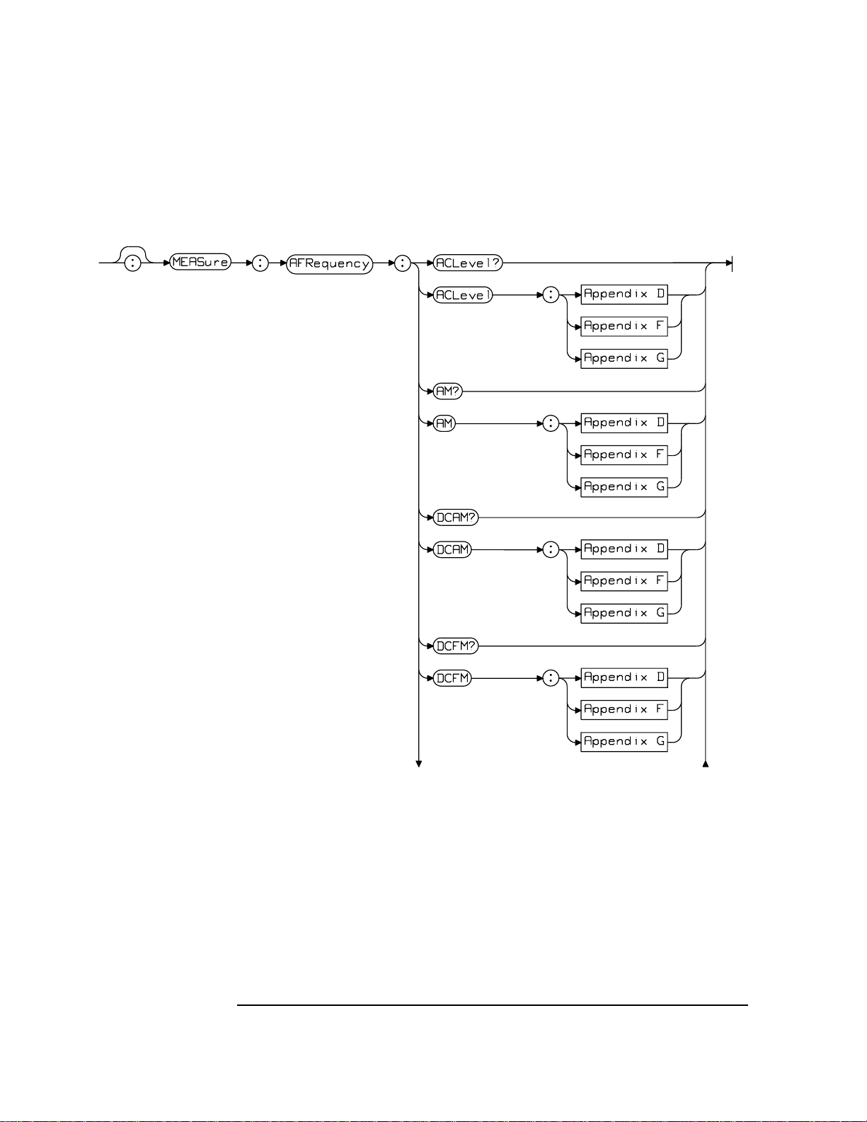
Audio Frequency Commands (Measure Subsystem)
5-2
Continued Over
Page 93

Audio Frequency Commands (Measure Subsystem)
5-3
Page 94

Audio Frequency Commands (Measure Subsystem)
ACLevel
ACLevel
Description Sets the AC Level MEASurement attributes.
GPIB unit is V.
Display units are dBm, V, mV, uV, dBuV, W; default unit is V.
Queries the AC Level MEASurement result for AF Analyzer inputs.
(AFAN:INP) that are in units of AC level.
Syntax MEASure:AFRequency:ACLevel?
MEASure:AFRequency:ACLevel[:MM] | [:AVG] | [:MET]
Options Refer to Appendices D, F and G.
AM
Description Sets the AM Depth MEASurementattributes.Queries the AM Depth MEASurementresult
for AF Analyzer inputs (AFAN:INP) that are units of percent.
GPIB unit is %(PCT).
Display units are %(PCT).
Syntax MEASure:AFRequency:AM?
MEASure:AFRequency:AM[:MM] | [:AVG] | [:MET]
Options Refer to Appendices D, F and G.
DCAM
Description Sets the DC AM Level MEASurement attributes. Queries the DC Level MEASurement
result for AF Analyzer inputs (AFAN:INP) that are units of percent.
GPIB unit is %(PCT).
Display units are %(PCT).
Syntax MEASure:AFRequency:DCAM?
MEASure:AFRequency:DCAM[:MM] | [:AVG] | [:MET]
Options Refer to Appendices D, F and G.
5-4
Page 95

Audio Frequency Commands (Measure Subsystem)
DCFM
DCFM
Description Sets the DC FM Level MEASurement attributes. Queries the DC Level MEASurement
result for AF Analyzer inputs (AFAN:INP) that are units of Hertz.
GPIB unit is HZ.
Display units are KHZ, HZ; default unit is HZ.
Syntax MEASure:AFRequency:DCFM?
MEASure:AFRequency:DCFM[:MM] | [:AVG] | [:MET]
Options Refer to Appendices D, F and G.
DCVolts
Description Sets the DC VoltsMEASurement attributes.Queries the DC VoltsMEASurement result for
AF Analyzer inputs (AFAN:INP) that are units of DC Volts.
GPIB unit is V.
Display units are dBm, V, mV, uV, dBuV, W; default unit is V.
Syntax MEASure:AFRequency:DCVolts?
MEASure:AFRequency:DCVolts[:MM] | [:AVG] | [:MET]
Options Refer to Appendices D, F and G.
DISTortion
Description Sets the DISTortion MEASurement attributes. Queries the DISTortion MEASurement
result.
GPIB and Display units are dB and percent (PCT).
Default HP-IB and display unit is PCT.
Syntax MEASure:AFRequency:DISTortion?
MEASure:AFRequency:DISTortion[:MM] | [:AVG] | [:MET]
Options Refer to Appendices D, F and G.
5-5
Page 96

Audio Frequency Commands (Measure Subsystem)
FM
FM
Description Sets the FM deviation MEASurement attributes.Queries the FM deviation MEASurement
result for FM DEMOD AF Analyzer.
GPIB unit is HZ.
Display units are kHZ, HZ; default unit is HZ.
Syntax MEASure:AFRequency:FM?
MEASure:AFRequency:FM[:MM] | [:AVG] | [:MET]
Options. Refer to Appendices D, F and G
FREQuency
Description Sets the Audio FREQuency MEASurement attributes. Queries the Audio FREQuency
MEASurement result.
GPIB unit is HZ.
Display units are KHZ, HZ; default unit is HZ.
Syntax MEASure:AFRequency:FREQuency?
MEASure:AFRequency:FREQuency[:MM] | [:AVG] | [:MET]
Options Refer to Appendices D, F and G.
SELect
Description Selects/queries the Audio FRequency SELected measurement. NOTE: to get valid
measurements for DC AM, DC FM and DC Volts, this filed must be set to ’DC LEVEL’
and the AF Analyzer Input (AFAN:INP) is set to look at an AM, FM, or voltage source
(respectively).
Syntax MEASure:AFRequency:SELect?
MEASure:AFRequency:SELect <string>
Options ’AF FREQ’ | ’DC LEVEL’ | ’DISTN’ | ’SINAD’
5-6
Page 97

Audio Frequency Commands (Measure Subsystem)
SINad
Description Sets the SINad MEASurement attributes. Queries the SINad MEASurement result.
GPIB and Display units are dB and percent (PCT)
Default GPIB and Display unit is dB
Syntax MEASure:AFRequency:SINad?
MEASure:AFRequency:SINad[:MM] | [:AVG] | [:MET]
Options Refer to Appendices D, F and G.
SINad
5-7
Page 98

Audio Frequency Commands (Measure Subsystem)
SINad
5-8
Page 99

6
Bit Error Test Subsystem
6-1
Page 100

Bit Error Test Subsystem
6-2
 Loading...