

The first choice for GSM mobile service and repair
Troubleshoot and find faults fast with the Agilent
Technologies 8922S GSM MS service test set. Use it
to reduce false failures with a test set that combines versatility with ease-of-use.
Serving the needs of the GSM mobile manufacturer
Maximize production throughput and minimize the
cost per test with the 8922M GSM MS test set. It
offers the highest speed of test in its class
while guaranteeing accurate and repeatable
measurements.
Expand to DCS1800 or PCS1900
Add the 83220A/E test set to test DCS1800 and
PCS1900 mobiles.
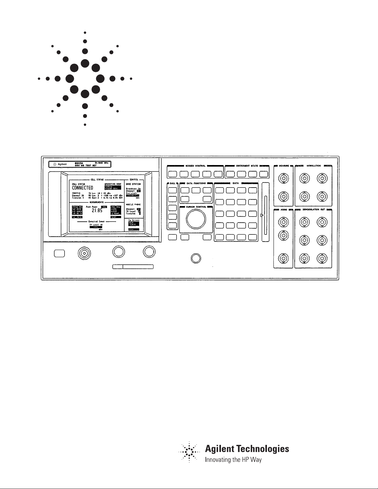
Agilent 8922S, 8922M, 83220E
GSM mobile test solutions
Data Sheet

2
5
5
5
6
9
9
9
10
10
10
10
11
11
11
11
11
11
11
11
11
12
12
12
12
12
14
14
14
15
Agilent 8922S/M test set specifications
GSM functionality
RF generator
RF analyzer
Spectrum analyzer
Audio source
Audio analyzer
Oscilloscope
Remote programming
General
Reference
Product options
High stability timebase
Transit protection
Spectrum analyzer
Test SIM card
Micro test SIM card
Protocol logging
Agilent 83212B GSM/DCS1800 MS test software
Associated equipment
Recommended accessories
Agilent system engineering assistance
Agilent 83220E DCS/PCS test set specifications
RF generator
RF analyzer
General
Reference
Ordering information
Differences between the 8922S/M test sets and
8922F/H test sets
Table of Contents
3
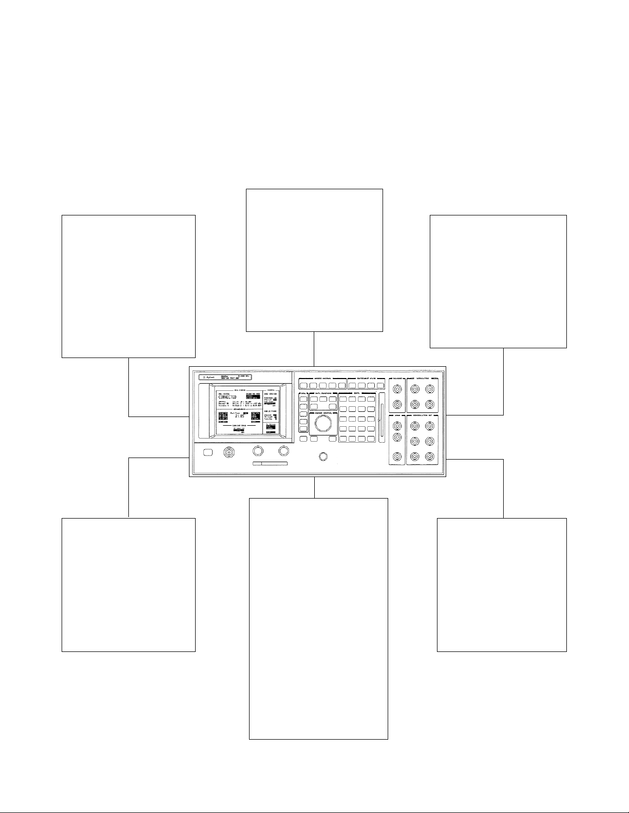
Switch on one of Agilent Technologies’ GSM test
sets and you’ll find your mobile finds service
immediately. Now make a call and you’re up and
running; ready to perform all the key transmitter
and receiver measurements. Built-in to every test
set you’ll find . . .
Transmitter tester
Transmitter measurements such
as power versus time, modulation
phase and frequency error, and
burst timing are made using a
fast DSP analyzer. There’s also
an accurate peak power meter
to perform the GSM average Tx
power measurement, taking samples only during the active part of
the burst.
Receiver tester
Receiver testing is done using an
accurate 0.3 GMSK source. The
wide dynamic range allows for
low-level sensitivity measurements
and high power tests to check for
receiver saturation. Mobile receiver
sensitivity is measured by making
bit-error-rate measurements on
Class Ia, Ib and II bits in either
raw or residual form.
Spectrum analyzer
The optional spectrum analyzer
completes the array of GSM measurements which can be made. It
provides high dynamic range pulse
on/off ratio measurements and
output RF spectrum tests. The
spectrum analyzer also makes an
excellent diagnostic tool for tracing
signals and finding problems.
Toolkit
The full-featured tool-kit includes
a power meter, CW RF synthesizer, audio synthesizer, frequency
vounter, DVM, audio analyzer,
oscilloscope and DSP Analyzer.
These tools can be configured
to measure just about any signal
a GSM phone can produce,
whether on a call or in test-mode.
Base station emulator
The GSM base station emulator
creates a test network to which the
mobile can camp and make calls.
The emulator is capable of causing
a ‘simple camp’ so that receiver
and transmitter functions can be
verified separately. A speech coder
is present to allow functional voice
testing. A variety of basic call processing features test the mobile as
if it were in a real network. These
features include hopped traffic
channels, call origination and
termination (both mobile and base
station), hand-overs, channel
assignments, Tx power control
commands and a choice of control
channel configurations.
Automatic software
The optional automatic test software is easy to use, fast and
simple to configure. With the
flexibility to allow test sequences
to be created and saved in minutes, automatic test software
personalizes the test set for each
part of the incoming inspection
or repair process.

4
Troubleshoot in test mode
What if the mobile is unable to find service and
make a call and you can’t find the source of the
problem? With a single key press, the test set can
be put into a special test mode, allowing un-synchronized mobile operation. The transmit and
receive portion of the mobile can then be measured separately.
Simplify mobile test
SIM (Subscriber Identity Module) cards are available to simplify mobile test by matching the information on the card (IMSI, MCC, MNC) with that on
the test set. They also enable the mobile to be put
into a special loop-back mode to perform the
receiver bit-error-rate test.
Compatibility
If you already own an 8922F/H test set, these can
be upgraded to 8922S/M. Contact your Agilent
Technologies representative for details. You can
take advantage of the higher performance without
re-writing your production test code. Code written
for the 8922G or 8922H test set is compatible with
the 8922M.
To facilitate traceable testing, the 8922S/M test sets generally follow the procedures as outlined in the associated
GSM recommendations, but do not necessarily meet the
exact requirements or cover all ranges, limits or conditions
required for type testing.
Agilent 8922S/M tests Associated
GSM specifications
11.10 tests
Transceiver frequency bands II.2.1.1
Transceiver RF channels and numbering II.2.1.2
Transceiver frequency hopping II.2.1.3
Transceiver spurious emissions
1
II.2.2
Tx peak transmitted power II.3.3
Tx RF spectrum due to switching
2
II.3.4
Tx RF spectrum due to modulation
2
II.3.4
Tx amplitude envelope II.3.3
(top 30 dB, and –70 dBc point)
Tx phase error and frequency error II.3.1
Rx sensitivity II.4.2
Rx usable input level range II.4.3
Rx co-channel rejection
3
II.4.4
Rx adjacent channel rejection II.4.5
(same frequency/different timeslot)
(different frequency/same timeslot)
3
Rx intermodulation rejection
3
II.4.6
Rx blocking and spurious response
4
II.4.7
Timebase tuning range Production test
1 The 8922S/M have limited capability for this measurement (< 1 GHz, and limited
resolution bandwidth and spans).
2 The 8922S/M test set use a 3 pole resolution bandwidth filter to make these
measurements.
3 8922M test set only; an additional RF source, such as the 8657 Option 022 0.3
GMSK signal generator, is required to make this measurement.
4 An additional CW RF source (frequency range of 100 kHz to 12.75 GHz, no modu-
lation needed) is required to make this measurement.

5
Specifications describe the instrument’s warranted performance and apply after a 30 minute warm-up. These
specifications are valid over its operating/environmental
range unless otherwise noted.
Supplemental characteristics (shown in italics) are intended to provide additional information, useful in applying the
instrument by giving typical (expected), but not warranted
performance parameters. These characteristics are shown
in italics or labeled as ‘typical,’ ‘useable to’ or ‘nominal.’
GSM functionality
Bit/frame error rate Class Ia, Ib, and Class II bits
measurements: in both raw and residual form.
MS power output 0 to 15 with RF analyzer auto
level control: adjust.
Broadcast channel BCCH + CCCH or
capability: BCCH + CCCH + SDCCH/4.
Control channels BCCH + CCCH, BCCH + CCCH
(SDCCH, FACCH, SACCH): + SDCCH/4, SDCCH/8 (non-
hopped), SACCH/FACCH.
Call control capabilities: BS originated cell (FS/EFS),
MS originated call (FS/EFS),
MS camp-on, BS call disconnect,
MS call disconnect.
Traffic channels: TCH (FS/EFS)–HSCSD
Timing: Auto, manual, uplink-downlink
and offset measurement.
Hopping: Two independent, user definable
MA tables with offsets.
Speech encoding/decoding: Full rate speech.
Speech echo mode: User selectable delay 0 to 5
seconds.
Measurement coordination: Flexible control of burst type,
ARFCN and timeslot.
SACCH MEAS result: RXLEV, RXQUAL and timing
advance.
RF generator specifications
Frequency
Range: 10 MHz to 1 GHz.
Resolution: 1 Hz.
Accuracy: Reference accuracy ± 0.5 Hz.
Stability: Same as reference.
Supplemental characteristics
Frequency overrange: To 1015 MHz with uncalibrated
output and modulation.
Switching speed: 577 ms over the GSM frequency
bands
1
in hop mode (refer to 0.3
GMSK modulation specs).
Output
RF in/out connector
Level range: –14 to –127 dBm, max overrange
power > -12 dBm max.
Level resolution: 0.1 dB.
Level accuracy
2
GSM bands:
1
±1.0 dB, levels ≥ –127 dBm.
±1.0 dB, typically for levels
≥ –127 dBm while hopping.
50 MHz to 1 GHz:
± 1.5 dB, levels ≥ -107 dBm;
± 2.0 dB, levels ≥ -127 dBm.
10 MHz to 50 MHz:
± 2.0 dB, levels ≥ -107 dBm;
± 2.5 dB, levels ≥ -127 dBm.
Reverse power: 15 W continuous. 100 W for 10
seconds/minute.
SWR: 1.5:1.
Aux RF out connector
Level range: +4 to –127 dBm.
Level resolution: 0.1 dB.
Level accuracy
GSM bands:
5
±1.0 dB, levels ≥ –107 dBm.±1.0
dB, typically for levels ≥ –107
dBm while hopping.
50 MHz to 1 GHz: ± 1.5 dB, levels ≥ -107 dBm;
± 2.0 dB, levels ≥ -127 dBm.
10 MHz to 50 MHz: ± 2.0 dB, levels ≥ -107 dBm;
± 2.5 dB, levels ≥ -127 dBm.
Reverse power: 200 mW.
SWR: 2.0:1, level < –4 dBm.
Spectral purity
Spurious signals: (for ≤ +1 dBm output level at aux
RF out, or ≤ –19 dBm output
level at RF in/out.)
Harmonics: < –25 dBc.
Non-harmonics: < –50 dBc, > 5 kHz offset from
carrier.
Agilent 8922S/M test set specifictions
1 GSM frequency bands are 880 to 915 MHz and 925 to 960 MHz.
2 Level accuracy degrades 0.2 dB when using the RF in/out connector for both
RF generator and RF analyzer. In 30 dB pulse mode, level accuracy specifications
are typical.
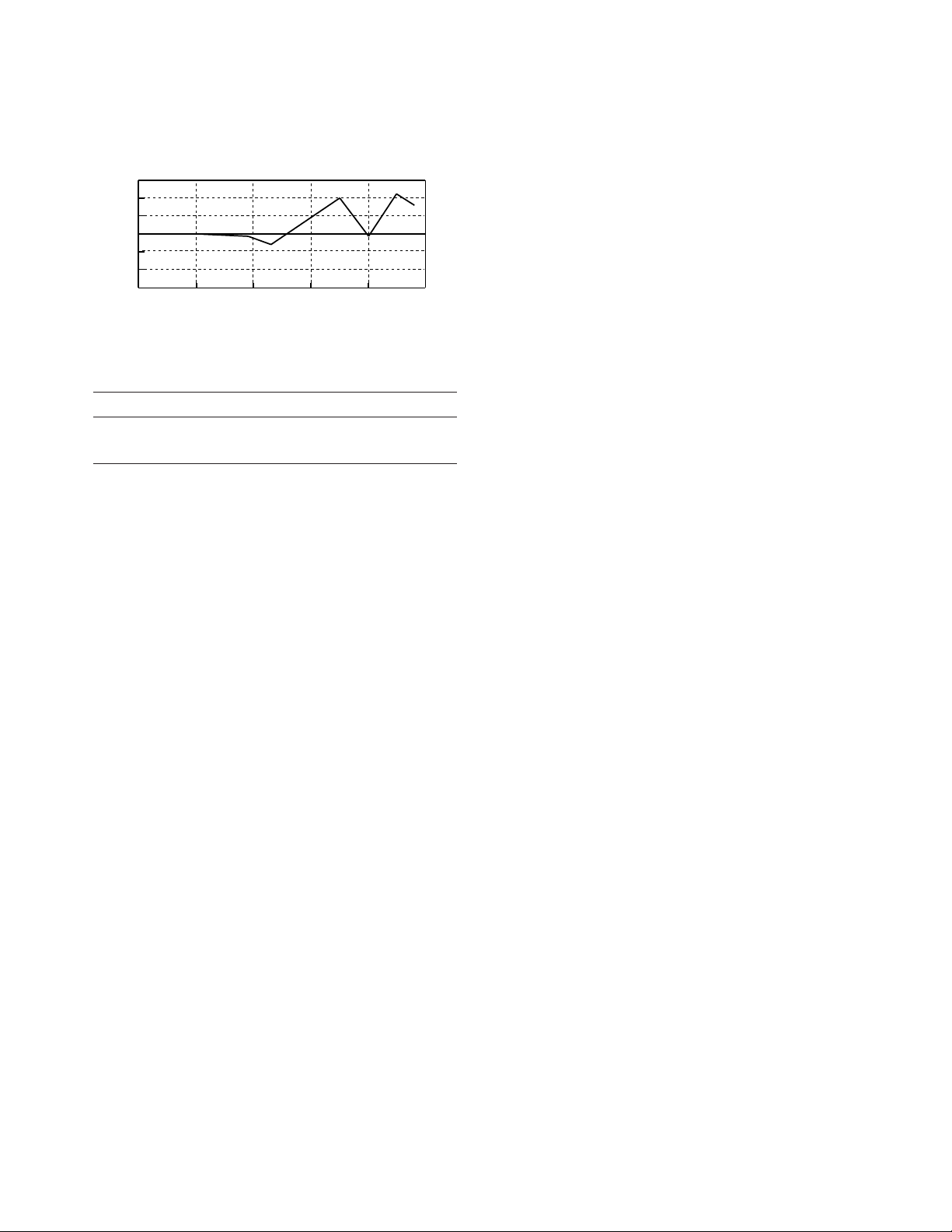
Typical RF generator RF in/out level error at -104 dBm
1
0.5
0
Error (dB)
-0.5
-1
925 930 935 940 945 950 955 960
Frequency (MHz)

6
0.3 GMSK modulation
After one timeslot, 577 ms, from an isolated RF generator trigger
in the GSM frequency bands.
1
Phase error: ≤ 1° rms.
Peak phase error: ≤ 4° peak.
Frequency error: ± [0.02 ppm (18 Hz) + reference
accuracy], for normal bursts.
Typically ± [0.03 ppm (27 Hz) +
reference accuracy], for RACHs.
Amplitude flatness: ± 0.25 dB peak.
Clock input (8922M test set only)
Frequency: 270.833 kHz ± 2 Hz (relative to
reference).
Level: TTL.
Data input (8922M test set only)
Format: Non differentially encoded input.
Level: TTL.
Supplemental characteristics
After three timeslots, 1.73 ms, from an isolated RF generator trigger in the GSM frequency bands.
5
Phase error: ≤ 0.5° rms.
Peak phase error: ≤ 2.0° peak.
Frequency error: ± [0.01 ppm (9 Hz) + reference
accuracy] for normal bursts.
Typically ± [0.02 ppm (18 Hz) +
reference accuracy] for RACH
bursts.
Pulse modulation
Input levels (8922M test set only): TTL.
Rise/fall time (10% to 90%): ≤ 5 µs.
Supplemental characteristics
On/off ratio: > 80 dB.
30 dB pulse modulation (8922M test set only)
All timeslots 30 dB higher than desired/active timeslot, to test
adjacent timeslot rejection.
Input levels: TTL.
Rise/fall time (10 to 90%): ≤ 5 µs.
AM for level control (8922M test set only)
For output levels ≤ +1 dBm at aux RF out or ≤-19 dBm at RF in/out.
Supplemental characteristics
Input
Range: -1.0V to +0.6V.
Impedance: 600 ohm nominal, dc coupled.
Sensitivity: 100% AM per volt, nominal.
Calibration: 0 Vdc input produces calibrated
output from the RF generator.
Rise/fall time (10 to 90%): ≤ 10 µs.
RF analyzer specifications
Frequency
Range: 10 MHz to 1 GHz.
Resolution: 1 Hz.
Hop mode
Resolution: 100 kHz.
Offset frequency: ≤ 50 kHz.
Offset resolution: 1 Hz.
RF in/out SWR: < 1.5:1.
Supplemental characteristics
Frequency overrange: To 1015 MHz.
Offset resolution: 500 Hz for FM demodulation out.
CW RF frequency measurement
Range: 10 MHz to 1 GHz.
Level range
RF in/out: -6 to +41 dBm.
Aux RF in: -36 to +20 dBm.
Input frequency setting range: ± 500 kHz.
Accuracy: ± (1 Hz + reference accuracy).
Supplemental characteristics
Minimum resolution: 1 Hz.
CW RF power measurements (RF in/out only)
Range: 90 MHz to 1 GHz.
Level range: -5 to +41 dBm.
Input frequency setting range: ± 500 kHz.
Accuracy: (+4 to +41 dBm) ± 0.5 dB ±
noise effects (0.2 mW).
Supplemental characteristics
Minimum resolution: 0.01 dB.
Accuracy: (-5 to +4 dBm) ± 0.5 dB ± noise
effects (0.2 mW).
Peak transmitter carrier power measurement
RF in/out only. After one timeslot, 577 µs, from an isolated receiver hop trigger in the GSM bands.
1
Range: 90 MHz to 1 GHz.
Level range: -5 to +41 dBm.
Input frequency setting range: ± 10 kHz.
Input level setting range: ± 3 dB.
Accuracy: (+4 to +41 dBm) ± 0.6 dB ±
noise effects (0.2 mW).
Supplemental characteristics
Minimum resolution: 0.2 dB.
Accuracy: (-5 to +4 dBm) ± 0.6 dB ± noise
effects (0.2 mW).
1. GSM frequency bands are 880 to 915 MHz and 925 to 960 MHz.

7
Typical power measurement accuracy 880 to 915 MHz
Typical power measurement acuracy +41 to -5 dBm
Pulse on/off ratio measurement (requires option 006)
‘On’ power is averaged over the useful part of the burst. ‘Off’ is
averaged over a one bit interval centered at a user specified time.
Non-hopped mode only.
Input frequency setting range: ± 10 kHz.
Input level setting range: ± 3 dB.
Timing accuracy: ± 1.7 µs (± 1.1 ms typical).
Accuracy (on/off ≥ 40 dB, RF in/out only):
Off power (dBm) On/off ratio accuracy
–30 to –1 ± 2.4 dB ± 1.1 dB typically
–37 to –30 ± 2.9 dB ± 1.3 dB typically
–41 to –37 ± 3.7 dB ± 1.7 dB typically
–47 to –42 ± 4.2 dB ± 2.1 dB typically
Amplitude envelope measurement
After one timeslot, 577 µs, from an isolated receiver hop trigger in
the GSM frequency bands.
1
Measurement range
RF in/out: -6 to +41 dBm.
Aux RF in: -36 to +20 dBm.
Input frequency setting range: ± 10 kHz.
Inaccuracy due to noise (for overshoots 1 dB):
Relative Input level setting error
level
± 1 dB ± 3 dB ± 3 dB w/5
averages
0 dB < ± 0.15 dB < ± 0.2 dB < ± 0.2 dB
peak peak peak
–6 dB < ± 0.2 dB < ± 0.3 dB < ± 0.3 dB
–30 dB < +3.0 dB < +4.2 dB < +2.2 dB
–3.8 dB –7.5 dB –2.6 dB
Phase and frequency measurements
After one timeslot, 577 µs, from an isolated receiver hop trigger in
the GSM frequency bands.
1
Range
RF in/out: -6 to +41 dBm.
Aux RF in: -36 to +20 dBm.
Input frequency setting range: ± 10 kHz.
Input level setting eange: ± 3 dB.
RMS phase error accuracy: ≤ 1° rms.
RMS phase error uncertainty versus measured value
Peak phase error accuracy: ≤ 4° peak.
Frequency error accuracy: ± [0.02 ppm (18 Hz) + reference
accuracy], for normal bursts.
Typically ± [0.03 ppm (27 Hz) +
reference accuracy] for RACH
bursts.
Supplemental characteristics
After three timeslots, 1.73 ms, from an isolated receiver hop trigger in the GSM frequency bands.
1
RMS phase error accuracy: ≤ 0.5° rms.
Peak phase error accuracy: ≤2° peak.
Frequency error accuracy: ± [0.01 ppm (9 Hz) + reference
accuracy], for normal bursts.
± [0.02 ppm (18 Hz) + reference
accuracy], for RACH bursts.
0.6
0.4
0.2
0
-0.2
-0.4
Accuracy (dB)
-0.6
870 880 890 900 910 920
Frequency (MHz)
Measurement Power Level is +33 dBm
0.6
0.4
0.2
0
-0.2
-0.4
Accuracy (dB)
-0.6
-1 0 0 10 2 0 3 0 40
Power (dBm)
Measurement Frequency is 975 MHz
0.6
0.5
0.4
0.3
0.2
Uncertainty (Deg rms)
0.1
0
0 0.5 1 1.5 2 2.5 3 3.5 4 4.5 5 5.5
Specified Typical
Measured Result (Deg rms)

8
0.3 GMSK data recovery (8922M test set only)
After one timeslot, 577 ms, from an isolated receiver hop trigger in
the GSM frequency bands.
1
Range
RF in/out: -6 to +41 dBm.
Aux RF in: -36 to +20 dBm.
Input frequency setting error: ± 100 Hz.
Required input phase
accuracy: ≤5° rms, ≤20° peak.
Demodulation duty cycle: 1 timeslot per frame.
Outputs: Data, clock, and data valid.
Data output clock: Clocked at 1 MHz rate.
Delay, data: ≤ 1 frame (4.62 ms).
Output level: TTL.
FM demodulation output (Agilent 8922M test set only)
Range
RF in/out: -6 to +41 dBm.
Aux RF in: -36 to +20 dBm.
Sensitivity: 20 µV/Hz ± 5% (into an open cir-
cuit).
Input frequency setting range: ± 50 kHz, with ≤100 kHz
peak deviation
Input level setting range: ±3 dB.
Supplemental characteristics
3 dB bandwidth: DC to 270 kHz.
Output impedance: 600 ohm.
DC offset: ≤5 mV.
Pulse demodulation output (8922M test set only)
Range
RF in/out: -6 to +41 dBm.
Aux RF in: -36 to +20 dBm.
Input frequency setting range: ± 50 kHz.
Input level setting range: ±3 dB.
Rise time (10 to 90%): ≤ 2.5 µs.
Fall time (90 to 10%): ≤2.5 µs.
Supplemental characteristics
Output impedance: 600 ohm, dc coupled.
Output level: 2 Vpeak into an open circuit.
Output RF spectrum measurement (requires option 006)
After one timeslot, 577 ms, from an isolated receiver hop trigger in
the GSM frequency bands.
1
Range
RF in/out: -6 to +41 dBm.
Aux RF in: -36 to +20 dBm.
Input levels for optimum dynamic range
RF in/out: +7, +17, +27, +37 dBm.
Aux RF in: -23, -13, -3, +7 dBm.
Input frequency setting range: ± 10 kHz.
Input level setting range: ± 3 dB.
Supplemental characteristics
Log linearity: ± 0.4 dB.
Amplitude flatness: ± 1.0 dB.
Amplitude resolution: 0.4 dB.
Dynamic range (dB): This describes the spectrum analyzer resolu-
tion bandwidth filter used when measuring output RF spectrum. The
dynamic range of the measurement will be a combination of this filter response and the modulation spectrum of the incoming signal.
Offset (kHz)
100 200 300 400 600 800 to 1800
Range (dB) 24 42 53 60 63 64
When using output RF spectrum due to the ramping measurement,
the dynamic range is decreased by 12 dB (due to peak hold).
Spectrum analyzer specifications (option 006)
Frequency range: 10 MHz to 1 GHz.
Frequency span/resolution
Bandwidth (coupled):
Span Bandwidth
< 50 kHz 300 Hz
< 200 kHz 1 kHz
< 1.5 MHz 3 kHz
≤ 4 MHz 30 kHz
Display: Log, 10 dB/div.
Display range: 80 dB.
Log linearity: ± 1.1 dB.
Reference level
RF in/out: +44 to -24 dBm.
Aux RF in: +23 to -55 dBm.
Non-harmonic -50 dBc max, for inputs
spurious responses: ≤ 30 dBm.
Residual responses: < -70 dBm (no input signal,
0 dB attenuation).
Image rejection: > 50 dB.
Supplemental characteristics
Level accuracy: ±2.5 dB.
Frequency overrange: To 1015 MHz.
Displayed average noise level: <-116 dBm (0 dB attenuation,
< 50 kHz spans).
1. GSM frequency bands are 880 to 915 MHz and 925 to 960 MHz.

9
Frequency span/resolution Bandwidth (coupled):
Span Bandwidth
≤ 50 MHz 30 kHz
Audio source specifications
Frequency
Range: DC to 25 kHz.
Accuracy: 0.025% of setting.
Supplemental characteristics
Minimum resolution: 0.1 Hz.
Output level
Range: 0.1 mV to 4 V
rms
.
Maximum output current: 20 mA peak.
Output impedance: < 1 ohm.
Accuracy: ± (2% of setting + resolution).
Residual distortion (THD + noise, 0.1%, 20 Hz to 25 kHz in 80
amplitude > 200 mVrms): kHz BW.
Supplemental characteristics
Minimum resolution: Level ≤ 0.01 V: 50 µV.
Level ≤ 0.1 V: 0.5 mV.
Level ≤ 1 V: 5 mV.
Level > 1 V: 50 mV.
DC coupled offset: < 50 mV.
Audio analyzer specifications
Frequency measurement
Range: 20 Hz to 400 kHz.
Accuracy: ±(0.02% + 1 count + reference
accuracy).
External input: 20 mV
rms
to 30 V
rms
.
Supplemental characteristics
Minimum resolution: f < 10 kHz: 0.01 Hz.
f < 100 kHz: 0.1 Hz.
f ≥ 100 kHz: 1 Hz.
AC voltage measurement
Voltage range: 0 V to 30 V
rms
.
Accuracy (20 Hz to 15 kHz),
input > 1 mV
rms
: ±3% of reading.
Residual noise + THD 175 µV.
(15 kHz BW):
Supplemental characteristics
3 dB bandwidth: 2 Hz to 100 kHz.
Input impedance: 1 Mohm, 145 pF at audio in.
Minimum resolution: 4 digits for inputs ≥ 100 mV.
3 digits for inputs < 100 mV.
DC voltage measurement
Voltage range: 100 mV to 42 V.
Accuracy: ± (1.0% of reading + DC Offset).
DC offset: ± 45 mV.
Supplemental characteristics
Minimum resolution: 1.0 mV.
Distortion measurement
Fundamental frequency: 1 kHz ± 5 Hz.
Input level range: 30 mV
rms
to 30 V
rms
.
Display range: 0.1% to 100%.
Accuracy: ±1 dB (0.5 to 100% distortion).
Residual THD + noise The greater of -60 dB or
(15 kHz BW): +175 µV.
Supplemental characteristics
Minimum resolution: 0.01% distortion.
Audio filters
There are seven filters used in the 8922 test set. 50 Hz HPF,
300 Hz HPF, 300 Hz LPF, 3 kHz LPF, 15 kHz LPF, 750 µs de-emphasis,
1 kHz notch.

10
Audio detectors
The audio detectors available in the 8922 are: Pk+, pk-, pk + hold,
pk - hold, pk ±/2, pk ±/2 hold, pk ± max, pk ± max hold, RMS.
Oscilloscope specifications
Frequency range (3 dB): 2 Hz to 50 kHz.
Scale/division: 10 mV to 10 V in 1, 2, 5
and 10 steps.
Amplitude accuracy ± 1.5% of reading ±
(20 Hz to 10 kHz): 0.1 division.
Time/division: 10 µs to 100 µs in 1, 2, 5
and 10 steps.
External trigger level: TTL.
Maximum voltage
Scope in: 5 V peak.
Audio in: 30 V
rms
.
Supplemental characteristics
3 dB bandwidth: Typically > 100 kHz.
Internal DC offset: ≤ 0.1 division for ≥
50 µV/div sensitivity.
Remote programming
GPIB: Agilent’s implementation of IEEE
Standard 488.2.
Functions implemented: SH1, AH1, T6, L4, SR1, RL1, LE0,
TE0, PP0, DC1, DT1, C4, C11, E2.
RS-232: 3 wire RJ-11 connector used for
serial data in and out.
Baud rates: 1200, 2400, 4800, 960, and 19200
selectable.
Printer support
RS-232: 3 wire RJ-11 connector used for
serial data in and out.
Centronics parallel interface.
General specifications
Size: 177 H x 426 W x 574 D mm
(7 x 16.75 x 23 inch).
Weight: 32 kg, 70 lbs.
Operating temperature: 0° to +55°C.
Storage temperature: -40° to +70°C.
Power: 100, 120, 220, 240 Vac, 48 to 440
Hz, ± 10% of line voltage, maximum 450 VA.
EMI: Meets the requirements of the
European, EMC directive
89/336/EEC.
Safety: Certified to IEC 348:1978 and
CSA-22.2, No. 231.
Video output: The video out connector on the
rear panel outputs a 15 kHz PAL
CVBS underscanning compatible
signal.
Supplemental characteristics
Leakage: At RF generator output levels
< -40 dBm, typical leakage is
< 1 µV induced in a resonant
dipole antenna one inch away
from any surface except the
rear panel.
Reference specifications
The accuracy needs for testing GSM radios require the unit to be
operated with the high stability reference (option 001) or an external high stability reference.
Accuracy (after warm up): ± [(Time since calibration x
aging rate) + temperature effects
+ accuracy of calibration].
External reference input
Frequency: 13, 10, 5, 2 or 1 MHz, ± 30 ppm.
Level: 0 to +10 dBm.
Supplemental characteristics
Nominal impedance: 50 ohm.
10 MHz out (rear panel BNC)
Level: > +8.0 dBm nominal.
Impedance: 50 ohm nominal.
13 MHz out (rear panel BNC)
Level: > +8.0 dBm nominal.
Impedance: 50 ohm nominal.
Fixed reference mode
Aging: < 2 ppm/year.
Temperature stability: ± 1 ppm (0° to 55°C).
Warm-up time: < 30 minutes, ± 2 ppm of final
frequency.
Tunable reference mode
Allows offsetting the internal reference by a selected amount relative
to the high stability reference (option 001) or an external reference.
Required external ± 0.5 ppm.
reference accuracy:
Tune range: ± 30 ppm.
Reference accuracy: ± 1 ppm + accuracy of external
reference or high stability (option
001).
Temperature stability: ≤ 4 ppm, for selected offsets of
up to ± 30 ppm.

11
High stability timebase (option 001)
Option 001 adds a high stability timebase with the following specifications.
Aging: < 5 x 10
-4
ppm/day after 24 hour
warm-up.
< 0.1 ppm/year for
continuous operation.
Temperature stability: < 2.5 x 10
-3
ppm/°C
(0° to +55°C).
Warm-up time: Within 5 x 10
-4
ppm of final value
10 minutes after turn on, at 25°C.
Supplemental characteristics
Opt 001 ref out (rear panel BNC to be connected to ref in).
Frequency: 10 MHz nominally.
Level: +7.5 dBm nominally.
Transit protection (option 002)
Option 002 adds accessories which protect the Agilent 8922S/M
test set during handling and transport. This option adds a rugged
front panel cover, extended rear feet, and accessory pouch. The
snap-on front cover protects the CRT and front panel from impact
damage. The extended rear feet allow the unit to stand vertically
with cables attached to the rear panel.
Spectrum analyzer (option 006)
Option 006 adds a 10 to 1000 MHz spectrum analyzer to the
8922S/M test set. This provides output RF spectrum (due to modulation or switching) and pulse on/off measurements as well as
general purpose capabilities.
Test SIM card (option 007)
Option 007 adds a credit-card size test SIM (subscriber identity
module).
Micro test SIM card (option 008)
Option 008 adds a micro-size test SIM (subscriber identity module).
Protocol logging (special option H03)
Special option H03 provides software and a connecting cable that
enables GSM layer 2 and 3 messages to be logged to an ASCII
file. The software runs on an MS-DOS
®
compatible PC.
Protocol monitoring (option 003)
Option 003 provides an interface for connecting the 8922M test
set to the 37900D protocol analyzer.
The 37900D protocol analyzer may be used to continuously monitor
the protocol link in real time between the mobile and 8922 base station simulator.
Agilent 83212D GSM/DCS1800/PCS1900 MS
test software (option 012)
Option 012 includes a copy of the 83212B
GSM/DCS1800/PCS1900/MS test software with the 8922S/M
test set. This software runs on the 8922S/M I-BASIC controller to
provide automatic testing of mobiles. For DCS1800/PCS1900 testing, the 83220A/E DCS/PCS test set is also needed.
Associated equipment
83210A service kit: Includes extender boards, cables and service
manual (08922-90108).
85700A: 32 kbyte static RAM memory card.
85702A: 128 kbyte static RAM memory card.
85704A: 256 kbyte static RAM memory card.
85705A: 512 kbyte static RAM memory card.
85701A:128 kbyte OTP ROM memory card.
85703A: 256 kbyte OTP ROM memory card.
08922-61062: High stability reference (option 001) retrofit kit.
08922-61070: Transit protection (option 002) retrofit kit.
08922-61845: Spectrum analyzer (option 006) retrofit kit.
9211-2661: Transit case for the 83220E test set.
9211-2662: Transit case for the 8922S/M test set.
8657A/B: Synthesized signal generator
(Option 022): 0.3 GMSK modulator.
11759C: RF channel simulator.
8590E-Series: Spectrum analyzers.
85715B: GSM900 transmitter measurements personality.
85722B: DCS1800 transmitter measurements personality.
Recommended accessories
10438A: Miniature oscilloscope probe (high impedance/40 pF 1:1
probe).
54006A: 6 GHz resistive divider probe kit.
34118B: Test lead kit.
1250-1263: BNC (male) to single banana plug.
08920-61060: Antenna.
Agilent systems engineering assistance
Extra assistance from Agilent Technologies in the form of system
installation, productivity assistance, programmer or user training,
or solution consulting are available. Call for a quote.
The 83220E test set extends the 8922S/M test set to test DCS1800
and PCS1900 mobiles. Specifications are identical to the 8922S/M
test set with the following exceptions:
Product options
MS-DOS is a US registered trademark of Microsoft Corporation.

12
RF generator specifications
Frequency
Range: 1805 to 1990 MHz. 1710 to 1785
MHz (83220A test set only)
Output
RF in/out connector
Level range: -19 to -127 dBm.
Level accuracy: ± 1.0 dB, levels ≥-127 dBm.
± 1.0 dB, typically for levels ≥
-127 dBm while hopping.
Reverse power: 2 W continuous.
SWR: <1.5:1.
Aux RF output connector (83220A test set only)
Level Range: +5 to -127 dBm
Level Resolution: 0.1dB.
Level Accuracy: ±1.0 dB, levels≥-127 dBm.
±1.0 dB, typically for levels ≥
-127 dBm while hopping.
Reverse power: 200 milliwatts.
SWR: 2.0:1.
0.3 GMSK modulation
Frequency error: ± (0.01 ppm (22 Hz) + reference
accuracy), for normal bursts.
Typically ± (0.02 ppm (32 Hz) +
reference accuracy), for RACHs.
Supplemental characteristics
Frequency error: ± (0.005 ppm (9 Hz) + reference
accuracy), for normal bursts.
±(0.01 ppm (18 Hz) + reference
accuracy), for RACH bursts.
AM for level control (8922M test set only)
For output levels ≤ -25 dBm at RF in/out.
Rise/fall time (10 to 90%): < 20 µs.
RF analyzer specifications
Frequency
Range: 1710 to 1990 MHz.
CW RF frequency measurement
Range: 1710 to 1990 MHz.
Level Range
RF in/out: -13 to +32 dBm.
Aux/RF in: - 23 to +20dBm (83220A test set
only).
CW RF power measurement
Range: -5 to +32 dBm.
Accuracy: (≥ 0 dBm, 1710 to 1880 MHz) ±
0.5 dB ± noise effects (0.015 mW).
Supplemental characteristics
Accuracy (-5 to 0 dBm, 1880 to 1990 MHz): ± 0.5 dB ± noise
effects (0.015 mW).
Accuracy (-5 to +32 dBm, 1710 to 1990 MHz): See graph.
Minimum resolution (> 0 dBm): 0.01 dB.
Peak transmitter carrier power measurement
(RF in/out only)
Range: -5 to +32 dBm.
Accuracy: (≥ 0 dBm, 1710 to 1880 MHz)
± 0.6 dB ± noise effects (0.015
mW).
Supplemental characteristics
Accuracy (-5 to 0 dBm, 1880 to 1990 MHz): ± 0.6 dB ± noise
effects (0.015 mW).
Accuracy (-5 to +32 dBm, 1710 to 1990 MHz): See graph.
Minimum resolution 0.2 dB.
( ≥ 0 dBm):
Power measurement accuracy 1710 to 1990 MHz
Power measurement accuracy +32 to -5 dBm
83220E DCS/PCS test set specifications
0.6
0.4
0.2
0
-0.2
-0.4
Accuracy (dB)
-0.6
1600 1700 1800 1900 2000 2100
Measurement Power Level is 0 dBm
Frequency (MHz)
0.6
0.4
0.2
0
-0.2
-0.4
Accuracy (dB)
-0.6
-10 0 10 20 3 0 40
Power (dBm)
Measurement Frequency is 1880 MHz
13
RF generator level accuracy 1710 to 1990 MHz
Pulse on/off ratio measurements
Off power (dBm) On/off ratio accuracy
-48 to -19 ± 2.4 dB (± 1.1 dB typically)
-55 to -48 ± 2.9 dB (± 1.3 dB typically)
Amplitude envelope measurement
Measurement range
RF in/out: -13 to +32 dBm.
AUX/RF in: -23 to +23 (83220A test set only).
Phase and frequency measurement
Measurement range
RF in/out: -13 to +32 dBm.
AUX/RF in: -23 to +23 (83220A test set only).
Frequency error accuracy: ± (0.01 ppm (22 Hz) + reference
accuracy), for normal bursts.
Typically ± (0.02 ppm (32 Hz) +
reference accuracy ), for RACHs.
Supplemental characteristics
Frequency error accuracy: ± (0.005 ppm (9 Hz) + reference
accuracy), for normal bursts.
± (0.01 ppm (18 Hz) + reference
accuracy ), for RACH bursts.
0.3 GMSK data recovery
Range
RF in/out: -13 to +32 dBm.
AUX/RF in: -23 to +23 (83220A test set only).
FM demodulation output (8922M test set only)
Range
RF in/out: 13 to +32 dBm.
AUX/RF in: -23 to +23 (83220A test set only).
Pulse demodulation output (8922M test set only)
Range
RF in/out: -13 to +32 dBm.
AUX/RF in: -23 to +23 (83220A test set only).
Output RF spectrum measurement
Range
RF in/out: -13 to +32 dBm.
AUX/RF in: -23 to +23 (83220A test set only).
Input levels for optimum dynamic range
RF In/Out: -3, +2, +7, +12, +17, +22, +27,
+32 dBm.
AUX/RF in: -23 to +23 (83220A test set only).
Spectrum analyzer specifications
Frequency range: 1710 to 1990 MHz.
Reference level range
RF in/out: +35 to -45 dBm.
AUX/RF in: -23 to +23 (83220A test set only).
General specifications
Size
83220E: 133 H x 426 W x 574 D mm
(5.25 x 16.75 x 23 inch).
83220A/E + 8922: 310 H x 426 W x 574 D mm
(12.25 x 16.75 x 23 inch).
Weight
83220E: 16.3 kg, 36 lbs.
83220A/E + 8922S/M: 48.3 kg, 106 lbs.
Safety: Meets IEC 348 and CSA 556B.
Power: 100, 120, 220, 240 Vac, 48 to 440 Hz, ± 12% of line voltage,
approximately 200 VA (83220A/E test set) or 640 VA (83220A/E +
8922 test sets).
Reference specifications
External reference input
Supplemental characteristics
10 MHz out (rear panel BNC)
Level: > +9.0 dBm nominal.
13 MHz out (rear panel BNC)
Level: > +9.0 dBm nominal.
0.6
0.4
0.2
0
-0.2
-0.4
Accuracy (dB)
-0.6
1750 1800 1850 1900 1950 2000
Frequency (MHz)
Measurement Power Level is -127 dBm

14
8922S GSM MS service test set
Option 001: High stability timebase.
Option 002: Transit protection (provides front panel cover, and
extended rear feet).
Option 006: Spectrum analyzer.
Option 007: Test SIM card.
Option 008: Micro test SIM card.
Option 012: Mobile station test software.
Option 0B1: Provides a total of two sets of user’s guides (08922-
90211), service manuals (08922-90213) and programmers reference guide (08922-90212).
Option 0B3: Adds service manual (08922-90213).
Option AX4: Rack mount flange kit (5062-4072).
8922M GSM MS test set
Option 001: High stability timebase.
Option 002: Transit protection (provides front panel cover, and
extended rear feet).
Option 006: Spectrum analyzer.
Option 007: Test SIM card.
Option 008: Micro test SIM card.
Option 012: Mobile station test software.
Option 0B1: Provides a total of two sets of user’s guides (08922-
90211), service manuals (08922-90213) and programmers reference guide (08922-90212).
Option 0B3: Adds service manual (08922-90213).
Option AX4: Rack mount flange kit (5062-4072).
83220E DCS1800 MS test set
Option 022: Bundle discount when ordered with 8922S/M test
set.
Option 0B1: Provides one additional user’s guide, part number
83220-90027 (83220A/E test set)
Option AX4: Rack mount flange kit (5062-4071).
Supported printers and printer accessories
HP DeskJet 500, 500C, 550C and 560C.
GPIB, RS-232 and Centronics* interfaces are supported.
*Operation with Centronics printers requires the following accessories:
ITEL–45CHVE: MicroPrint GPIB/Centronics bus converter.
F1011A: AC/DC adapter.
C2912B: 3m centronics cable.
10833D: 0.5m GPIB cable.
8922S/M test set (Special option K06).
Serial printer connector and cable (RJ11 to D-type RS-232).
For more information on GSM test solutions from Agilent
Technologies, see the 8922S/M test set photocards (p/n 59646587E and 5964-6585E), 83212B test set product overview (p/n
5962-0196E) and the 8590E-Series technical data sheet (p/n 50919025E).
Ordering Information

15
8922F/H to 8922S/M test sets upgrades
Keeping in line with our policy to offer continual
enhancements for our instruments, customers who
already have an 8922F or 8922H may upgrade
them to the functionality of the 8922S or 8922M
respectively. The electronic attenuator is not
included in the upgrade.
The upgrades are in the form of retrofit kits which
must be installed at an Agilent service center.
The upgrades are structured as options on an
8922U product. The 8922U does not exist as a
product in its own right, only the options may be
ordered.
Ordering information
8922U option 101: Upgrade 8922H test set to 8922M
test set excluding electronic attenuator. For the
8922G option R10, 8922G option R72, 8922H (all
options).
8922U option 102: Upgrade the 8922F test set to the
8922S test set excluding electronic attenuator. For
the 8922E option R12 8922E option R71, 8922E
option R73 and 8922F (all options).
Differences between the 8922S/M test sets and 8922F/H test sets
Agilent 8922S and 8922F test set differences
Feature 8922S test set 8922F test set
Measurement speed Approx 10% increase in throughput n/a
Multi-burst measurement capability Yes No
GSM phase II power levels Yes No
E-GSM frequency bands Yes No
Electronic attenuator Yes No
SMS cell broadcast Yes No
Peak carrier power meter range -5 to +41 dBm +4 to +41 dBm
RF generator power level range -14 to -127 dBm -13 to -127 dBm
Burst-by-burst BER measurement Yes No
Screen freeze facility Yes No
IMSI attach/detach function Yes No
Agilent 8922M and 8922H test set differences
Feature 8922M test set 8922H test set
Measurement speed 10 to 20% increase in throughput n/a
Multi-burst measurement capability Yes No
GSM phase II power levels Yes Yes with FW > B.06.00
E-GSM frequency bands Yes No
Electronic attenuator Yes No
SMS cell broadcast Yes Yes with FW > B.06.00
Peak carrier power meter range -5 to +41 dBm +4 to +41 dBm
RF generator power level range -14 to -127 dBm -13 to -127 dBm
Burst-by-burst BER measurement Yes No
Screen freeze facility Yes No
Flash firmware upgrades by GPIB Yes No
IMSI attach/detach function Yes Yes with FW > B.06.00
General comments
The 8922S/M are software compatible with the 8922F/H test set. There will still be an 8922G compatibility
mode for backwards compatibility with existing test software.

Agilent Technologies’ Test and Measurement
Support, Services, and Assistance
Agilent Technologies aims to maximize the value you receive,
while minimizing your risk and problems. We strive to ensure
that you get the test and measurement capabilities you paid
for and obtain the support you need. Our extensive support
resources and services can help you choose the right Agilent
products for your applications and apply them successfully.
Every instrument and system we sell has a global warranty.
Support is available for at least five years beyond the production life of the product. Two concepts underlie Agilent’s
overall support policy: “Our Promise” and “Your Advantage.”
Our Promise
“Our Promise” means your Agilent test and measurement equipment will meet its advertised performance and functionality.
When you are choosing new equipment, we will help you with
product information, including realistic performance specifications and practical recommendations from experienced test
engineers. When you use Agilent equipment, we can verify that
it works properly, help with product operation, and provide
basic measurement assistance for the use of specified capabilities, at no extra cost upon request. Many self-help tools are
available.
Your Advantage
“Your Advantage” means that Agilent offers a wide range of
additional expert test and measurement services, which you
can purchase according to your unique technical and business
needs. Solve problems efficiently and gain a competitive edge
by contracting with us for calibration, extra-cost upgrades, outof-warranty repairs, and on-site education and training, as well
as design, system integration, project management, and other
professional services. Experienced Agilent engineers and technicians worldwide can help you maximize your productivity,
optimize the return on investment of your Agilent instruments
and systems, and obtain dependable measurement accuracy
for the life of those products.
By internet, phone, or fax, get assistance with all your
test and measurement needs.
Online Assistance
www.agilent.com/find/assist
Phone or Fax
United States:
(tel) 1 800 452 4844
Canada:
(tel) 1 877 894 4414
(fax) (905) 206 4120
Europe:
(tel) (31 20) 547 2323
(fax) (31 20) 547 2390
Japan:
(tel) (81) 426 56 7832
(fax) (81) 426 56 7840
Latin America:
(tel) (305) 269 7500
(fax) (305) 269 7599
Australia:
(tel) 1 800 629 485
(fax) (61 3) 9272 0749
New Zealand:
(tel) 0 800 738 378
(fax) (64 4) 495 8950
Asia Pacific:
(tel) (852) 3197 7777
(fax) (852) 2506 9284
Product specifications and descriptions in this
document subject to change without notice.
Copyright © 1996, 2000 Agilent Technologies
Printed in U.S.A. 5/00
5964-6586E
 Loading...