

Page 1

North American FM Tests
HP 11807A,E Option 001
Reference Guide
for the HP 8920A,B,D
HP Part No. 11807-90116
Printed in U. S. A.
March 1999
Rev C
1
Page 2

Copyright © Hewlett-Packard Company 1995
RESTRICTED
RIGHTS LEGEND
Use, duplication or dis closure by the U. S. Government is subje ct to restr ictions as
set forth in s ubparagra ph (c) ( 1) (ii) of the Rights in Technica l Data and Computer
Software clause in DFARS 252.227-7013.
Hewlett-Packard Company
3000 Hanover Street
Palo Alto, CA 94304. U.S.A.
Rights for non-DOD U.S. Gover nment Depa rtment s and Age ncies are a s set fort h
in FAR 52.227-19 (c) (1,2).
2
Page 3

Contents
Table of Contents
1 Product Description
HP 11807A,E Software 16
Finding the Information You Need 20
Additional Services Available 21
3
Page 4

Contents
A.14.00
2 Using the Software/HP 8920B or HP 8920A FW Above Rev.
Testing Overview 26
Customizing Testing 32
4
Page 5

Contents
3 Using the Software/HP 8920A FW Rev. Below A.14.00
Testing Overview 60
Customizing Testing 66
5
Page 6

Contents
4 Test, Parameter, and Pass/Fail Limit Descriptions
Introduction 90
TEST_01. TX and RX Stand-by Current Drain 91
TEST_02. TX Frequency Error 92
TEST_03. TX Output Power 93
TEST_04. TX Modulation Limiting 94
TEST_05. TX Audio Frequency Response 95
TEST_06. TX Audio Distortion 96
TEST_07. TX Microphone Sensitivity 97
TEST_08. TX FM Hum and Noise 98
TEST_09. TX Residual AM Hum and Noise 99
TEST_10. TX CTCSS/CDCSS Deviation, Freq/Code 100
TEST_11. RX Hum and Noise 101
TEST_12. RX Audio Distortion 102
TEST_13. RX Audio Frequency Response 103
TEST_14. RX Usable Sensitivity 104
TEST_15. RX Audio Squelch Sensitivity 105
TEST_16. RX Squelch Blocking 106
TEST_17. RX CTCSS/CDCSS Opening 107
TEST_18. RX Audio Sensitivity 108
6
Page 7

Contents
TEST_19. RX Variation of Sens with Freq 109
TEST_20. RX Quick Test 110
TEST_21. TX Quick Test 111
Test Parameter Descriptions 112
Parameter 1, RT External Pad and Cable Loss 113
Parameter 2, RT Full Rated System Deviation 114
Parameter 3, RT High Supply Voltage 115
Parameter 4, RT Low Supply Voltage 116
Parameter 5, RT Nominal Supply Voltage 117
Parameter 6, RX Audio Freq Response Step Frequency 118
Parameter 7, RX Audio Load Impedance 119
Parameter 8, RX CT/CDCSS Available 120
Parameter 9, RX CT/CDCSS Control 121
Parameter 10, RX CT/CDCSS Deviation 122
Parameter 11, RX Maximum Audio Power 123
Parameter 12, RX Set Radio Volume 124
Parameter 13, RX Squelch Blocking Step Frequency 125
Parameter 14, RX Squelch Control 126
Parameter 15, RX Squelch Preset Only 127
Parameter 16, RX Standard RF Input Level 128
7
Page 8

Contents
Parameter 17, RX Tolerance for Setting Volume 129
Parameter 18, RX Usable Sens Set and Measure 130
Parameter 19, RX Usable Sensitivity SINAD Level 131
Parameter 20, TX Audio Distn % Full Rated System Dev 132
Parameters 21-23, TX Audio Freq Response Start, Step, and Stop
Frequency 133
Parameter 24, TX CD/CTCSS Available 134
Parameter 25, TX CD/CTCSS Control 135
Parameter 26, TX CD/CTCSS Filter 1 Opt 136
Parameter 27, TX De-emphasis 137
Parameter 28, TX Dekey Between TX Tests 138
Parameter 29, TX Mic Sens Set and Measure 139
Parameter 30, TX Modulation Limiting Sweep Step Freq 140
Parameter 31, TX Output Power @Low Switch 141
Parameter 32, TX User/System Key UUT 142
Parameter 33, XX Secure Frequency Info 143
Pass/Fail Limit Descriptions (specifications) 144
Pass/Fail Limit 1, RX Audio Distn 17 dB Below Rated Power 145
Pass/Fail Limit 2, RX Audio Distortion 146
Pass/Fail Limit 3, RX Audio Freq Resp Delta from 6 dB/Oct 147
8
Page 9

Contents
Pass/Fail Limit 4, RX Audio Frequency Response Roll <0.5
kHz 148
Pass/Fail Limit 5, TX Audio Frequency Response Roll >2.5
kHz 149
Pass/Fail Limit 6, RX Audio Output @40% of Full Rated Dev 150
Pass/Fail Limit 7, RX CDCSS SINAD at Opening 151
Pass/Fail Limit 8, RX CT/CDCSS FM Hum and Noise 152
Pass/Fail Limit 9, RX CT/CDCSS Opening Level 153
Pass/Fail Limit 10, RX CTCSS SINAD at Opening 154
Pass/Fail Limit 11, RX Hum and Noise Squelched 155
Pass/Fail Limit 12, RX Hum and Noise Unsquelched 156
Pass/Fail Limit 13, RX Squelch Blocking 157
Pass/Fail Limit 14, RX Stand-by Current Drain 158
Pass/Fail Limit 15, RX Threshold Squelch Sensitivity 159
Pass/Fail Limit 16, RX Tight Squelch Sensitivity 160
Pass/Fail Limit 17, RX Usable Sensitivity 161
Pass/Fail Limit 18, RX Variation of Sens Delta Frequency 162
Pass/Fail Limit 19, TX Audio Distortion 163
Pass/Fail Limit 20, TX Audio Response Delta From 6 dB/oct 164
Pass/Fail Limit 21, TX Audio Frequency Response Roll <0.5
kHz 165
9
Page 10

Contents
Pass/Fail Limit 22, TX Audio Frequency Response Roll >2.3 kHz
for 896-940M 166
Pass/Fail Limit 23, TX Audio Response Roll >2.5 kHz 167
Pass/Fail Limit 24, TX Audio Frequency Response Roll >2.7 kHz
for 896-940M 168
Pass/Fail Limit 25, TX CT/CDCSS Deviation 169
Pass/Fail Limit 26, TX CTCSS Frequency Error 170
Pass/Fail Limit 27, TX Current Drain 171
Pass/Fail Limit 28, TX Deviation If Set an d Meas ur e Mic Se ns 172
Pass/Fail Limit 29, TX FM Hum and Noise 173
Pass/Fail Limit 30, TX Frequency Error 174
Pass/Fail Limit 31, TX Microphone Sensitivity 175
Pass/Fail Limit 32, TX Modulation Limiting 176
Pass/Fail Limit 33, TX Output Power 177
Pass/Fail Limit 34, TX Output Power at High Supply 178
Pass/Fail Limit 35, TX Output Power at Hi gh Sup ply Low SW 179
Pass/Fail Limit 36, Output Power at Low Supply 180
Pass/Fail Limit 37, TX Output Power at Low Supply Low SW 181
Pass/Fail Limit 38, TX Output Power at L ow Switch Setting 182
Pass/Fail Limit 39, TX Residual AM Hum and Noise 183
10
Page 11

Contents
5 Reference (Alphabetical)
Conventions Used 186
Copying Files 187
Data Collection (Saving and Retrieving Test Results) 189
Disks 198
Exiting a Program 200
HP-IB Control Annunciators 201
Memory Cards 202
Parameters 209
Pass/Fail Limits (specifications) 210
Pausing or Stopping a TEST 211
Printing 212
Procedures 225
RAM 230
Saving Te sts Results 232
Serial Port 233
Test Execution Conditions 234
USER Keys 236
11
Page 12

Contents
6 Problem Solving
If you have a problem testing your radio 240
If the test procedure doesn’t run on an test set 241
If the HP 11807A,E program was incorrectly loaded 242
If the printer does not pri nt the test resu lts 243
If the FM radio fails the audio tests 245
If radio volume can’t be set on the test set’s meter screen 246
If your radio fails CTCSS/CDCSS tests or the tests don’t run 247
If you can’t get the data-collection function to work 251
12
Page 13

Contents
Glossary 253
13
Page 14

Contents
Index 257
14
Page 15

1
Product Description
Chapter 1
Product Description
15
Page 16

Chapter 1, Product Description
HP 11807A,E Software
HP 11807A,E Software
The HP 11807A,E Option 001 Software performs fast, accurate, automated tests
that determine the RF and audio performance of FM radios. The measurement
methods and specifications used for these tests are based on methods and values
derived from the following industry standards:
EIA/TIA-603
EIA/TIA-204-D (TEST_19)
Materials Included in This Package
This package contains the following materials. Verify that all the materials are
present and inspect them for damage. If a part is missing or appears to be
damaged, contact your nearest Hewlett-Packard sales or service office.
• HP 11807A Option 001 Test Software (part number 11807-10001) or HP 11807E
Option 001 Test Software (part number 11807-10020)
• SRAM memory card (uninitialized), for saving your own test procedures and results.
• For 11807A, 32 Kbyte SRAM (part number 85700A).
• For 11807E, 64 Kbyte SRAM (part number 83230A).
• HP 11807A,E Option 001 Software Reference Guide (part number 11807-90116)
• HP software product license agreement
Additional Equipment Required
• HP 8920A (B or D) RF Communications Test Set
• HP 8920A Option 005: 512 Kbyte RAM Memo ry extension
16 S:\hp11807a\OPT001\USRGUIDE\BOOK\chapters\product.fb
Page 17

Recommended Equipment
• HP 8920 Option 001: High-Stability Timebase
• HP 8920 Option 004: Tone/Digital Signa ling
• HP 8920A Option 010: 400 Hz High-Pass Filter
• HP 8920A Option 013: C MESSAGE Weighting Filter
• External power supply An external power supply for the FM radio can be configured to
the HP 8920A in one of three ways:
1. A power supply or battery can be connected directly to the FM radio.
2. A power supply can be connected to the rear-panel DC CURRENT MEASUREMENT
banana-plug connectors. (This requires the HP 8920A Option 003, HP-IB/RS-232/
Current Measurement.)
3. A power supply can be controlled by the HP 8920A when it’s connected to the HP-
IB connector. (This re quires the HP 8920A Option 003, HP-IB/RS-232/D C Current
Measurement.)
Chapter 1, Product Description
HP 11807A,E Software
HP-IB programmable power supplies from the following series are supported for
external control:
HP 664xA
HP 665xA
HP 667xA
HP 668xA
NOTE: HP 662xA and HP 663xA series DC power supplies are not supported.
S:\hp11807a\OPT001\USRGUIDE\BOOK\chapters\product.fb
17
Page 18

Chapter 1, Product Description
HP 11807A,E Software
Ordering Upgrades
If your test set does not contain all of the required options you must update your
instrument accordingly. Order the necessary upgrade kit(s) from your local
Hewlett-Packard sales office. Regional sales offices are listed at the front of this
manual.
Required Upgrades
• HP 8920A Option R05: 512 Kbyte RAM expansion re trof it kit
Recommended Upgrades
• HP 8920A,B Option R01: High-Stability Timebase retrofit kit
• HP 8920A,B Option R04: Tone/Digital Signaling retro fit kit
• HP 8920A,B Option R10: 400 Hz High-Pass Filter (HPF) retrofit kit (A maximum of
two optional filters can be installed in your test set. If you already have two optional
filters installed, one of them must be removed before installing this kit.)
Available Tests:
• HP 8920A,B Option R13: C MESSAGE Weighting Filter retrofit kit (A maximum of
two optional filters can be installed in your test set. If you already have two optional
filters installed, one of them must be removed before installing this kit.)
The following tests can be performed with this software.
• TX and RX stand-by current drain
• TX frequency error
• TX output power
• TX modulation limiting
• TX audio frequency response
• TX audio distortion
• TX microphone sensitivity
• TX FM hum and noise
• TX residual AM hum and noise
• TX CTCSS/CDCSS deviation , freq/code
• RX hum and noise
• RX audio di stortion
• RX frequency response
18 S:\hp11807a\OPT001\USRGUIDE\BOOK\chapters\product.fb
Page 19

Software Features
Chapter 1, Product Description
HP 11807A,E Software
• RX usable sensitivity
• RX audio squelch sensitivity
• RX squelch blocking
• RX CTCSS/CDCSS opening
• RX audio sensitivity
• RX variation of sensitivity with frequency
• RX quick test
•TX quick test
For test, parameter, and specification descriptions, see chapter 4, "Test,
Parameter, and Pass/Fail Limit Descriptions" on page 89
.
The followin g features si mplify testing:
• While adjustments are being made, a large meter display and auditory feedback are
provided.
• Results of tests and pass/fail indications are displayed on the test set’s CRT, and can be
printed, or collected in a disk drive, memory card, PC, or HP palmtop computer.
• The software allows the operator to change the order of tests, pass/fail limits, test
parameters, and equipment configurations.
S:\hp11807a\OPT001\USRGUIDE\BOOK\chapters\product.fb
19
Page 20

Chapter 1, Product Description
Finding the Information You Need
Finding the Information You Need
This manual describes the setup and use of the HP 11807A,E Software with the
HP 8920A,B,D Test Set. The book is arranged in self-contained chapters to
provide the following information:
5
20 S:\hp11807a\OPT001\USRGUIDE\BOOK\chapters\product.fb
4
6
Page 21

Additional Services Available
Chapter 1, Product Description
Additional Services Available
Consult the HP 8920 User’s Guide or call the HP 8920 Hotline 1-800-922-8920
(in the USA and Canada only) and give your software model number.
S:\hp11807a\OPT001\USRGUIDE\BOOK\chapters\product.fb
21
Page 22

Chapter 1, Product Description
Additional Services Available
22 S:\hp11807a\OPT001\USRGUIDE\BOOK\chapters\product.fb
Page 23

2
Using the Software/HP 8920B or HP
8920A FW Above Rev. A.14.00
Using the Software Above FW
Rev. A.14.00
Chapter 2
23
Page 24

Chapter 2, Using the Software/HP 8920B or HP 8920A FW Above Rev. A.14.00
NOTE: The firmware revision A.14.00 in the HP 8920A,D had several enhancements, which are
standard in the HP 8920B. This chapter applies to users with:
• HP 8920A test sets with firmware revision above A.14.00
• All HP 8920B test sets.
The test set’s firmware revision is displayed on the top right corner of the
configuration screen.
• Press SHIFT CONFIG to display the configuration screen and read the firmware
revision.
If you have an HP 8920A test set with firmware revision below A.14.00, refer to
chapter 3, "Using the Software/HP 8920A FW Rev. Below A.14.00," on page
57. Contact Hewlett-Packard at 1-80 0-922-8920 for details on upgrading your
firmware if desired.
24 S:\hp11807a\OPT001\USRGUIDE\BOOK\chapters\softav14.fb
Page 25

Chapter 2, Using the Software/HP 8920B or HP 8920A FW Above Rev. A.14.00
The software can be run on the factory default settings or customized to your
individual needs and specific requirements. This chapter provides detailed
information on how to load, run, and customize the software.
The test set has two methods of accessing on-line help. In each of the screens in
the test environment, k4 (
Help) accesses specific information about how to set
up/use the current screen. SHIFT HELP accesses the master help file, with an
alphabetical listing of help topics.
25
S:\hp11807a\OPT001\USRGUIDE\ BOOK\chapters\softav14.fb
Page 26

Chapter 2, Using the Software/HP 8920B or HP 8920A FW Above Rev. A.14.00
Testing Overview
Testing Overview
Pressing TESTS will display what is called the TESTS (Main Menu) screen. To
begin testing, you must first load the software and make connections. From this
screen you have the option to:
Begin running tests:
• The factory default settings are acceptable for your application or
• The software has already been customized and saved to a memory card
Customize the software:
• Decide which te sts you desire to run (Order of Tests)
• you may want to run all, some, or just one of the tests.
• Specify which channels to test (Channel Information)
• you may want to test one, some, or all of the channels on your radio.
• Change the pass/fail limits for specific measurements (Pass/Fail Limits)
• you may want the pass/fail limits to have tighter or looser specifications than the
default settings.
• Change the test environment and conditions (Test Parameters)
• decide output format.
• enter specific information about radio equipment and/or environment.
• Save any or all of the above customized changes to a memory card (Save/Delete
Procedure)
Set Up Test Set:
• Print test results or ce rtain screens.
• Decide when and where test results are displayed (Execution Conditions/
Printer Setup)
26 S:\hp11807a\OPT001\USRGUIDE\BOOK\chapters\softav14.fb
Page 27

Chapter 2, Using the Software/HP 8920B or HP 8920A FW Above Rev. A.14.00
Testing Overview
5
27
S:\hp11807a\OPT001\USRGUIDE\ BOOK\chapters\softav14.fb
Page 28
Chapter 2, Using the Software/HP 8920B or HP 8920A FW Above Rev. A.14.00
Testing Overview
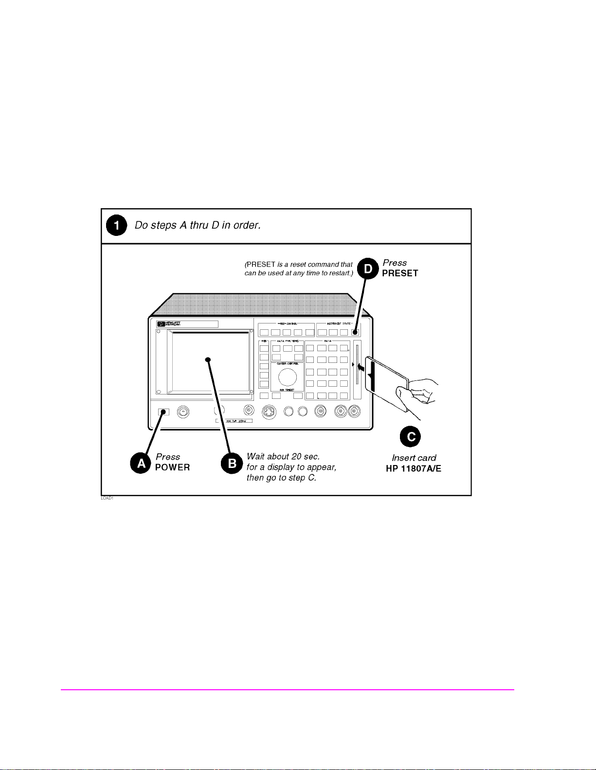
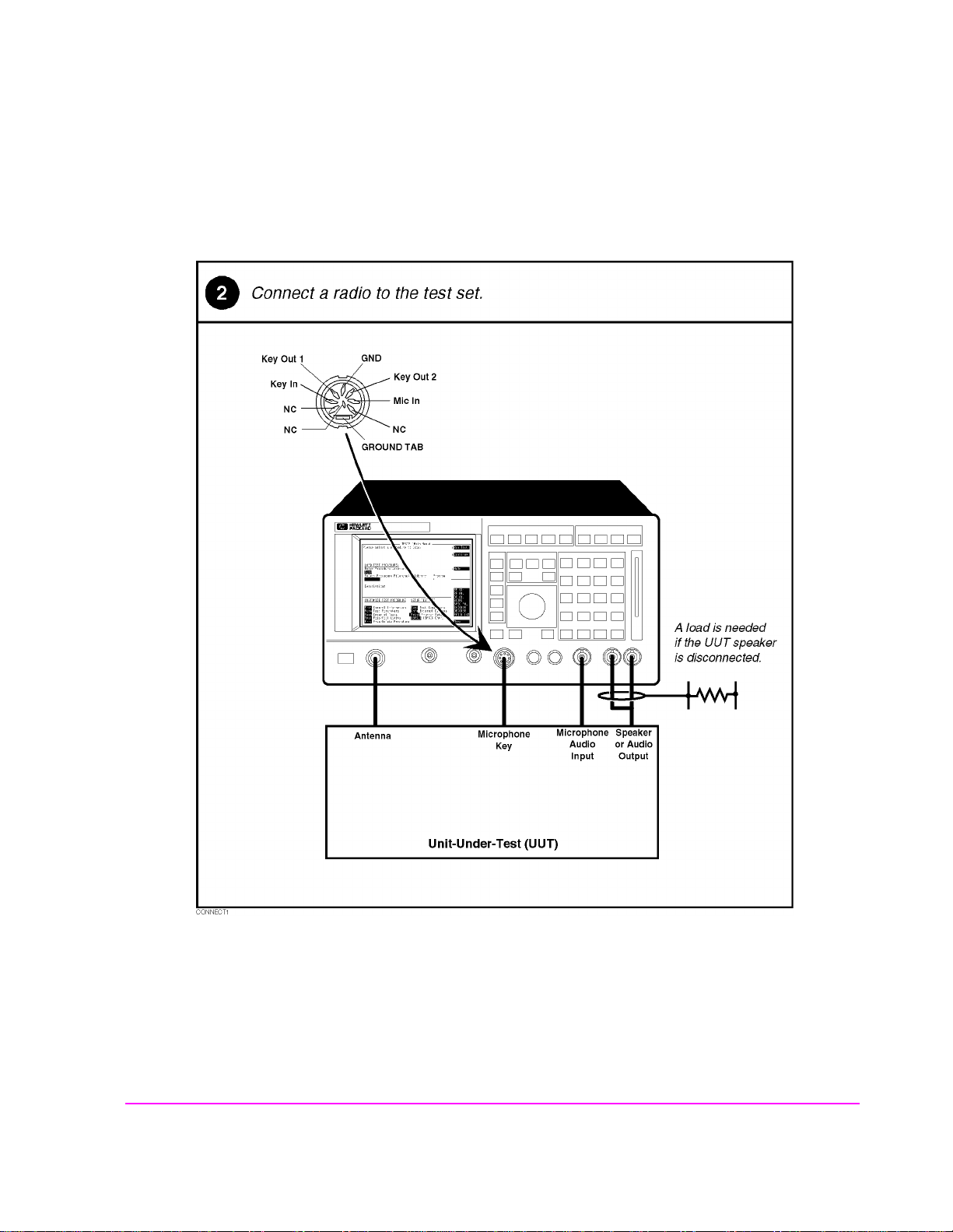
Setting Up the Test Set and Making Connections
Before you begin testing, you must set up the test set and make the appropriate
hardware connections.
28 S:\hp11807a\OPT001\USRGUIDE\BOOK\chapters\softav14.fb
Page 29
Chapter 2, Using the Software/HP 8920B or HP 8920A FW Above Rev. A.14.00
Testing Overview
Making a Connection
29
S:\hp11807a\OPT001\USRGUIDE\ BOOK\chapters\softav14.fb
Page 30

Chapter 2, Using the Software/HP 8920B or HP 8920A FW Above Rev. A.14.00
Testing Overview
Selecting a Test Procedure
To load the software , you must f irst se lect the location to load fr om (in th is case, i t
will be
Card) and a procedure filename. Your card comes pre-programmed with
at least one procedure. The actual software program does not get loaded into the
test set’s m emory until k1 (
Run Test) is selected. It will take approximately 15
seconds to load the software in an HP 8920B, and approximately two minutes in
an HP 8920A,D.
The software memory car d can be removed after the program is loaded into the
test set’s memory. The program will remain in memory after a power-down/
power-up cycle, unless it is manually deleted or a new program is loaded.
When tests begin to run, they are execute d in the order in whi ch they were entered
into the Test Procedure.
Pressing CANCEL will pause the current test (press k2 to continue the test.)
30 S:\hp11807a\OPT001\USRGUIDE\BOOK\chapters\softav14.fb
Page 31

Chapter 2, Using the Software/HP 8920B or HP 8920A FW Above Rev. A.14.00
Testing Overview
Selecting A Test Procedure
31
S:\hp11807a\OPT001\USRGUIDE\ BOOK\chapters\softav14.fb
Page 32

Chapter 2, Using the Software/HP 8920B or HP 8920A FW Above Rev. A.14.00
Customizing Testing
Customizing Testing
Because of the diversity of individual testing needs, the software has been
designed so that changes may be easily made from the test set’s front panel. You
may store these changes on a memory card so tha t you may skip the se steps in the
future. See
Because your needs change, the software allows changes to its default settings
whenever you need to make them. For example, tests may be inserted or deleted,
and later after runnin g the tes ts you ca n chang e the pas s/fail limits or decide to test
different channels.
Most testing customization is accomplished through the customization screens.
These customization screens are accessed from the main TESTS (Main Menu)
screen as shown in the following figure. Customizing procedures is explained
later in this chapter.
"Saving a Test Procedure" o n page 50.
NOTE: External Devices, Printer Setup, and IBASIC will not be explained in this customizin g
section.
• External Devices and Printer Setup are used when setting up printers and external disk
drives which is explained in "Disks" on page 198 and "Printing" on pag e 212 in
chapter 5.
• IBASIC is used when writing your own programs and is not explained in this manual.
If you need to write your own IBASIC programs you may acquire the following
manuals:
•8920A,D
• HP Instrument Basic User’s Handbook HP part number E2083-90000.
• HP 8920A Programming Manual HP part number 08920-90220.
•8920B
• HP Instrument Basic User’s Handbook Version 2.0
HP part number E2083-90005.
• HP 8920B Programming Manual HP part number 08920-90222.
32 S:\hp11807a\OPT001\USRGUIDE\BOOK\chapters\softav14.fb
Page 33

Chapter 2, Using the Software/HP 8920B or HP 8920A FW Above Rev. A.14.00
Customizing Testing
How to Customize Testing
33
S:\hp11807a\OPT001\USRGUIDE\ BOOK\chapters\softav14.fb
Page 34

Chapter 2, Using the Software/HP 8920B or HP 8920A FW Above Rev. A.14.00
Customizing Testing
Changing the Order of Tests
You may define the order of tests to include all, some, or just one of the tests
available. When the first test is finished, the next will run. The test sequence will
remain in the test set’s ba ttery backed-up memory until another test sequen ce is
loaded or set up. For information on saving a customized test sequence, see
"Saving a Test Procedure" on page 50.
Defining the order of tests is accomplished by inserting or deleting tests from the
list of tests that come with th e software package.
and Pass/Fail Limit Descriptions" on page 89
See chapter 4, "Test, Parameter,
, for descriptions of tests included in
this package.
All Chans? field allows the user to decide to run the test on all channels
The
entered in the
selected as
Channel Information table, or just the channels which are
Prime in the Channel Information screen. This feature allows the
user the flexi bil it y to use channels th a t a re sel ected as
sequence, and those indicated as non-prime in a subset of tests (those tests with a
Yes response in All Chans). For more informa tion, see "Spe cifying Channel
Information" on page 38
.
Prime in all the tests in the
The following descri bes how to creat e a n ew t est s equence and e nter a resp onse to
All Chans? field.
the
34 S:\hp11807a\OPT001\USRGUIDE\BOOK\chapters\softav14.fb
Page 35

Chapter 2, Using the Software/HP 8920B or HP 8920A FW Above Rev. A.14.00
Customizing Testing
How to Change the Order of Tests
35
S:\hp11807a\OPT001\USRGUIDE\ BOOK\chapters\softav14.fb
Page 36

Chapter 2, Using the Software/HP 8920B or HP 8920A FW Above Rev. A.14.00
Customizing Testing
36 S:\hp11807a\OPT001\USRGUIDE\BOOK\chapters\softav14.fb
Page 37

Chapter 2, Using the Software/HP 8920B or HP 8920A FW Above Rev. A.14.00
Customizing Testing
37
S:\hp11807a\OPT001\USRGUIDE\ BOOK\chapters\softav14.fb
Page 38

Chapter 2, Using the Software/HP 8920B or HP 8920A FW Above Rev. A.14.00
Customizing Testing
Specifying Channel Information
For each channel that you wish to specify, you must enter the following
information into the
• RX Freq (MHz)
• Enter the receive frequency of your radio in (MHz).
• TX Freq (MHz)
• Enter the transmit frequency of your radio in (MHz).
NOTE: Enter a −1 in the RX or TX test frequency fields to have all subsequent frequencies ignored
when testing is started.
• Sq Freq/Code (for RX Freq)
• If you are testing receiver CTCSS or CDCSS (test param eter 8 is set=1), yo u mu st
enter the receive squelch frequency or code. Otherwise, leave this field empty.
1. Enter a CTCSS frequency, for example, 91.5 Hz as “CT FR91.5”, or
2. Enter a CTCSS tone code, for example, “ZZ” for 91.5 Hz as “CT ZZ”. The tone
codes supported by the software are shown in table 17, "CTCSS Tone Codes"
on page 248, or
3. Enter a CDCSS code word, for example “CD 023” (octal). The code words
supported by the software are shown in table 18, "CDCSS Code Words" on
page 249.
• Sq Freq/Code (for TX Freq)
• If you are testing transmitter CTCSS or CDCSS (test parame ter 23 is set=1 ) , you
must enter the transmit squelch frequency or code. Otherwise, leave this field
empty.
1. Enter a CTCSS frequency, for example, 91.5 Hz as “CT FR91.5”, or
1. Enter a CTCSS tone code, for example, “ZZ” for 91.5 Hz as “CT ZZ”. The tone
codes supported by the software are shown in table 17, "CTCSS Tone Codes"
on page 248, or
2. Enter a CDCSS code word, for example “CD 023” (octal). The code words
supported by the software are shown in table 18, "CDCSS Code Words" on
page 249.
Channel Information screen:
38 S:\hp11807a\OPT001\USRGUIDE\BOOK\chapters\softav14.fb
Page 39

Chapter 2, Using the Software/HP 8920B or HP 8920A FW Above Rev. A.14.00
Customizing Testing
• Test? (yes/no) specifies whether you want to test the UUT at this channel. If set to
“No” then the UUT will not be tested at that channel, but you may retain the channel
information in the table for later use. If set to “Yes” then the channel will be used as
defined by settings of Prime? and All Chans? fields.
• Prime? (yes/no) specifies which channels are “prime”. Select “Yes” if you want to
test the UUT at this channel on all the tests in the procedure. Select No if you want to
test the UUT at this channel on just a subset of tests, which are design ated by s electing
Yes in the All Chans field of the Order of Tests screen. See All Chans?
in "Changing the Order of Tests " on page 34 for more information.
For information on saving the channel information table, see "Saving a Test
Procedure" on page 50
All Chans field in the Order of Tests screen interacts closely with the
The
Prime? field on the Channel Information screen. When the software runs, it
begins by retrieving the first channel entered into the
screen. It then checks the response in the
should be tested at that cha nne l at this ti me. If there is a
field, the software will go to the next channel in the table. If there is a
response in the
.
Channel Information
Test? field to determine if the UUT
No response in the Test?
Yes
Test? field, the software will check if the channel is Prime.
Yes response in the Prime? field indicates to test the UUT at that channel on
A
the entire sequence of tests in the procedure. A
No response in the Prime? field
indicates to te st t he UUT at t ha t c hannel on a subset of test s i n t he p roc edure. The
subset of tests is determined by a
Therefore, tests with a
No response in the All Chans? field will be run on prime
Yes response in the All Chans? field.
channels only.
39
S:\hp11807a\OPT001\USRGUIDE\ BOOK\chapters\softav14.fb
Page 40

Chapter 2, Using the Software/HP 8920B or HP 8920A FW Above Rev. A.14.00
Customizing Testing
Below is an exampl e o f how t he software would ru n i f you had a procedure set up
as follows:
Table 1
Chan # Test? Prime?
Chan 01 Yes Yes
Chan 02 Yes No
Chan 03 No No
Table 2
Test Number
Test 01 No
Test 02 Yes
Test 03 Yes
Test 04 No
All Chan?
Setting
The result would be:
• Chan 01 is used in Test 01, Test 02, Test 03, and Test 04.
• Chan 02 is used in Test 02, and Test 03 only.
• Chan 03 is not used.
40 S:\hp11807a\OPT001\USRGUIDE\BOOK\chapters\softav14.fb
Page 41

Table 3
Chapter 2, Using the Software/HP 8920B or HP 8920A FW Above Rev. A.14.00
Customizing Testing
The following table 3 shows how to properly confi gure these se ttings acc ording to
your testing needs.
Necessary Field Settings
Testing Need
Test? Prime? All Chan?
Test channel on all
tests in sequence
Test channel on a
subset of tes t s i n
sequence
Do not test this
channel now, but
retain information
for later use
Yes Yes Don’t Care
Yes No Yes on tests
you want
included in
the testing
subset
No Don’t Care Don’t Care
41
S:\hp11807a\OPT001\USRGUIDE\ BOOK\chapters\softav14.fb
Page 42

Chapter 2, Using the Software/HP 8920B or HP 8920A FW Above Rev. A.14.00
Customizing Testing
How to Specify Channel Information
42 S:\hp11807a\OPT001\USRGUIDE\BOOK\chapters\softav14.fb
Page 43

Chapter 2, Using the Software/HP 8920B or HP 8920A FW Above Rev. A.14.00
Customizing Testing
43
S:\hp11807a\OPT001\USRGUIDE\ BOOK\chapters\softav14.fb
Page 44

Chapter 2, Using the Software/HP 8920B or HP 8920A FW Above Rev. A.14.00
Customizing Testing
44 S:\hp11807a\OPT001\USRGUIDE\BOOK\chapters\softav14.fb
Page 45

Chapter 2, Using the Software/HP 8920B or HP 8920A FW Above Rev. A.14.00
Customizing Testing
Changing Pass/Fail Limits
Pass/Fail limits define the values a measurement’s result is compared against to
determine if the UUT meets its specified standards. Default values are set in the
test software. These default values may be changed to suit your particular
requirements.
The followin g describes h ow to change the pass/fail ( upper and lowe r) limits.
"Pass/Fail Limit Descriptions (specifications)," in chapter 4, on page 144
for
descriptions of each pass/fail limit. For information on saving customized pass/
fail limits, s ee
"Saving a Test Procedure" on page 50.
How to Change Pass/Fail Limits
See
45
S:\hp11807a\OPT001\USRGUIDE\ BOOK\chapters\softav14.fb
Page 46

Chapter 2, Using the Software/HP 8920B or HP 8920A FW Above Rev. A.14.00
Customizing Testing
46 S:\hp11807a\OPT001\USRGUIDE\BOOK\chapters\softav14.fb
Page 47

Chapter 2, Using the Software/HP 8920B or HP 8920A FW Above Rev. A.14.00
Customizing Testing
47
S:\hp11807a\OPT001\USRGUIDE\ BOOK\chapters\softav14.fb
Page 48

Chapter 2, Using the Software/HP 8920B or HP 8920A FW Above Rev. A.14.00
Customizing Testing
Changing the Test Parameters
The software uses parameter s to opt i mize the te st envi ronme nt and conditions for
your testing situation. Many of the test parameters are determined by examining
your test needs. The software comes with default settings for test parameters.
Review the defaults for your particular needs.
in chapter 4, on page 112
for descriptions of each test parameter. For information
on saving c ustomized test parameters, see
See "Test Parameter Descriptions,"
"Saving a Test Procedure" on page 50.
The following describes how you can change test parameters through the Test
Parameter screen to optimize your testing conditions.
How to Change the Test Environment and Conditions
48 S:\hp11807a\OPT001\USRGUIDE\BOOK\chapters\softav14.fb
Page 49

Chapter 2, Using the Software/HP 8920B or HP 8920A FW Above Rev. A.14.00
Customizing Testing
49
S:\hp11807a\OPT001\USRGUIDE\ BOOK\chapters\softav14.fb
Page 50

Chapter 2, Using the Software/HP 8920B or HP 8920A FW Above Rev. A.14.00
Customizing Testing
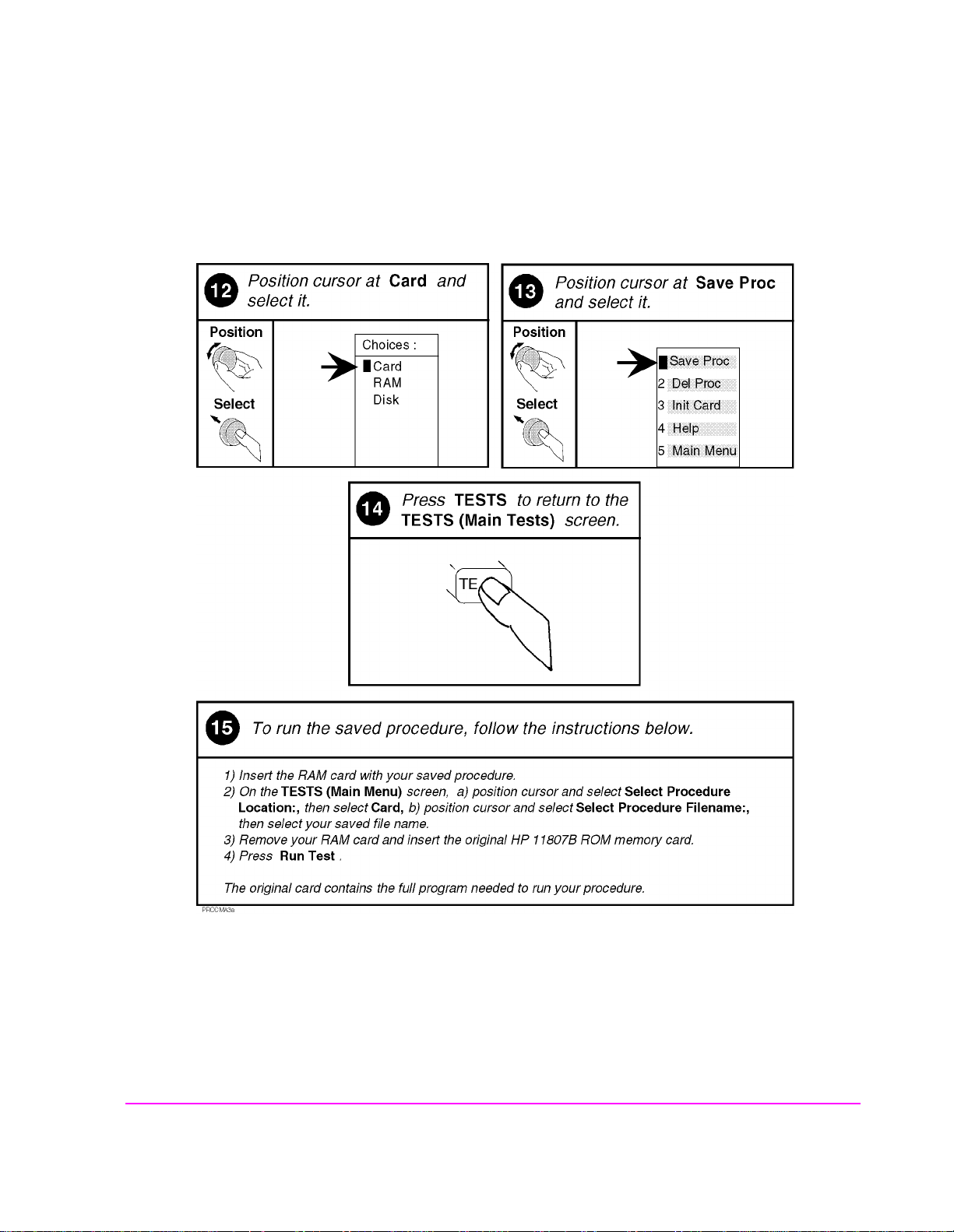
Saving a Test Procedure
A Test Procedure is a collection of channel information, test parameters, testing
order, and pass/fail limits saved in a file that customizes the test software to a
specific application. You may save the file to a memory card or disk.
When you save a procedure you will be saving channel information, test
parameters, pass/fail limits, and testing order, plus a library that contains the
names of all test parameters, pass/fail limits, and tests that are resident in the
software. The library file comes from the software and cannot be modified. The
library file will be automatically saved on the card or disk that is being used to
store the new test procedure.
The following example shows how to save a new procedure to a memory card.
For more information concerning procedures,
page 225
.
see "Procedures," in chapter 5, on
50 S:\hp11807a\OPT001\USRGUIDE\BOOK\chapters\softav14.fb
Page 51

Chapter 2, Using the Software/HP 8920B or HP 8920A FW Above Rev. A.14.00
Customizing Testing
How to Save a Test Procedure
5
5
51
S:\hp11807a\OPT001\USRGUIDE\ BOOK\chapters\softav14.fb
Page 52

Chapter 2, Using the Software/HP 8920B or HP 8920A FW Above Rev. A.14.00
Customizing Testing
52 S:\hp11807a\OPT001\USRGUIDE\BOOK\chapters\softav14.fb
Page 53
Chapter 2, Using the Software/HP 8920B or HP 8920A FW Above Rev. A.14.00
Customizing Testing
53
S:\hp11807a\OPT001\USRGUIDE\ BOOK\chapters\softav14.fb
Page 54

Chapter 2, Using the Software/HP 8920B or HP 8920A FW Above Rev. A.14.00
Customizing Testing
Changing Test Execution Conditions
Test Execution Conditions define where and when test output occurs . You
may decide to:
• Display output on CRT only, or display on CRT and print hardcopy (Output
Results To).
NOTE: If printing test results is desired, after selecti ng Printer, additional steps are necessary to
connect and configure the printer. See "Printing," in chapter 5, on page 212.
• Display (or print) only measurements that fail, or display (or print) all measuremen ts
that pass or fail (Output Results For).
• Enter a title for an output heading for the displayed or printed results (Output
Heading).
• Stop testing when a measurement fails or continue through all of the tests wit hout
stopping (If Unit-Under-Test-Fails).
• Pause between each measurement, or run through entire test (Test Procedure
Run Mode).
• Start the program automatically when the Test System is powered on. (Autostart
Test Procedure on Power-up)
Test Execution Conditions
is accessed from the SETUP TEST SET: list.
To change a default setting, position the cursor to the desired field. Pressing the
knob (”selecting”) will toggle the underlined selection.
Test Execution Conditions settings are not retained after a power-down/
power-up cycle, and will return to their default settings.
54 S:\hp11807a\OPT001\USRGUIDE\BOOK\chapters\softav14.fb
Page 55

Chapter 2, Using the Software/HP 8920B or HP 8920A FW Above Rev. A.14.00
Customizing Testing
How to Change Test Execution Conditions
Printing and Saving Test Results
Printing and saving test results are features of the software which require
additional equipment and configuration.
See "Printing," in chapter 5, on page 212
for detailed descriptions and instructions for these features.
S:\hp11807a\OPT001\USRGUIDE\ BOOK\chapters\softav14.fb
55
Page 56

Chapter 2, Using the Software/HP 8920B or HP 8920A FW Above Rev. A.14.00
Customizing Testing
56 S:\hp11807a\OPT001\USRGUIDE\BOOK\chapters\softav14.fb
Page 57

3
Using the Software/HP 8920A FW Rev.
Below A.14.00
57
Rev. A.14.00
Using the Software Below FW
Chapter 3
Page 58

Chapter 3, Using the Software/HP 8920A FW Rev. Below A.14.00
NOTE: The firmware revision A.14.00 in the HP 8920A,D had several enhancements, which are
standard in the HP 8920B. This chapter applies to users with:
• HP 8920A test sets with firmware revision below A.14.00
The test set’s firmware revision is displayed on the top right corner of the
configuration screen.
• Press SHIFT CONFIG to display the configuration screen and read the firmware
revision.
If you have an HP 8 920B or an HP 8920A with fir mware revis ion above A .14.00,
refer to chapter 2, "Using the Software/HP 8920B or HP 8920A FW Above
Rev. A.14.00," on page 23. Contact Hewlett-Packard at 1-800-922-8920 for
details on upgrading your firmware if desired.
58
S:\hp11807a\OPT001\USRGUIDE\BOOK\chapters\softbw14.fb
Page 59

Chapter 3, Using the Software/HP 8920A FW Rev. Below A.14.00
The HP 11807A software can be run on the factory default set tings or customize d
to your individual needs and the specific requirements. This chapter provides
detailed information on how to load, run, and customize the software.
S:\hp11807a\OPT001\USRGUIDE\BOOK\chapters\softbw14.fb
59
Page 60

Chapter 3, Using the Software/HP 8920A FW Rev. Below A.14.00
Testing Overview
Testing Overview
Pressing TESTS will display what is called the TESTS screen. To begin testing,
you must first load the softwar e and make connecti ons. From this scr een you have
the option to:
Begin running tests:
• The factory default settings are acceptable for your application or
• The software has already been customized and saved to a memory card
Customize the software:
• Decide which tests you desire to run (Edit Seqn)
• you may want to run all, some, or just one of the tests.
• Specify which channels to test (Edit Freq)
• you may want to test one, some, or all of the channels on your radio.
• Change the pass/fail limits for specific measurements (Edit Spec)
• you may want the pass/fail limits to have tighter or looser specifications than the
default settings.
• Change the test environment and conditions (Edit Parm)
• decide output format.
• enter specific information about radio equipment and/or environment.
• Save any or all of the above customized changes to a memory card (Proc Mngr)
Set Up Test Set:
• Print test results or ce rtain screens.
• Decide when and where test results are displayed (Edit Cnfg)
60
S:\hp11807a\OPT001\USRGUIDE\BOOK\chapters\softbw14.fb
Page 61

Chapter 3, Using the Software/HP 8920A FW Rev. Below A.14.00
Testing Overview
5
61
S:\hp11807a\OPT001\USRGUIDE\BOOK\chapters\softbw14.fb
Page 62

Chapter 3, Using the Software/HP 8920A FW Rev. Below A.14.00
Testing Overview
Setting Up the Test Set and Making Connections
Before you begin testing, you must set up the test set and make the appropriate
hardware connections.
62
S:\hp11807a\OPT001\USRGUIDE\BOOK\chapters\softbw14.fb
Page 63

Chapter 3, Using the Software/HP 8920A FW Rev. Below A.14.00
Making a Connection
Testing Overview
S:\hp11807a\OPT001\USRGUIDE\BOOK\chapters\softbw14.fb
63
Page 64

Chapter 3, Using the Software/HP 8920A FW Rev. Below A.14.00
Testing Overview
Selecting a Test Procedure
To load the software , you must f irst se lect the location to load fr om (in th is case, i t
will be
at least one procedure. The actual software program does not get loaded into the
test set’s m emory until k1 (
minutes to load the software in an HP 8920A,D.
The software memory car d can be removed after the program is loaded into the
test set’s memory. The program will remain in memory after a power-down/
power-up cycle, unless it is manually deleted or a new program is loaded.
When tests begin to run, they are execute d in the order in whi ch they were entered
into the Test Procedure.
Pressing CANCEL will pause the current test (press k2 to continue the test.)
Card) and a procedure filename. Your card comes pre-programmed with
Run Test) is selected. It will take approximately 2
64
S:\hp11807a\OPT001\USRGUIDE\BOOK\chapters\softbw14.fb
Page 65

Selecting A Test Procedure
Chapter 3, Using the Software/HP 8920A FW Rev. Below A.14.00
Testing Overview
S:\hp11807a\OPT001\USRGUIDE\BOOK\chapters\softbw14.fb
65
Page 66

Chapter 3, Using the Software/HP 8920A FW Rev. Below A.14.00
Customizing Testing
Customizing Testing
Because of the diversity of individual testing needs, the software has been
designed so that changes may be easily made from the test set’s front panel. You
may store these changes on an SRAM card so tha t you may skip the se steps in the
future.
on page 83
You may customize your software at any time. Because your needs change, the
software allows cha nges to i ts defa ult set tings when you need t o make them and i n
any order that you choose. For ex ample, tests may be inserted or del eted, and lat er
after running t he test s you can change th e pass /fail limits or decide to te st diff erent
channels.
Most testing customization is accomplished through the test set’s Test Function
screens. These Test Functi on scr eens a re acc ess ed fro m the main
shown in the following figur e. All Tes t Func ti ons are e xpl ained in this chapter by
function.
See "Saving a Test Procedure Using the Procedure Manager," in chapter 3,
.
TESTS screen as
NOTE: Edit Cnfg and IBASIC will not be explained in this customizing secti on.
• Edit Cnfg is used when setting up printers and external disk drives which is explained
in "Disks" on page 198and "Printing" on page 212 in chapter 5.
• IBASIC is used when writing your own programs and is not explained in this manual.
If you need to write your own IBASIC programs you may acquire the following
manuals:
• HP 8920A,D
• HP Instrument Basic User’s Handbook HP part number E2083-90000.
• HP 8920A Programming Manual HP part number 08920-90220.
• HP 8920B
• HP Instrument Basic User’s Handbook Version 2.0 HP
part number E2083-90005.
• HP 8920B Programming Manual HP part number 08920-90222.
66
S:\hp11807a\OPT001\USRGUIDE\BOOK\chapters\softbw14.fb
Page 67

Beginning Software Customization
All software customization begins by accessing the TESTS screen first and then
selecting the
TESTS screen, press TESTS on the front panel of the test set.
Test Function which will open the Choices menu. To acces s the
Chapter 3, Using the Software/HP 8920A FW Rev. Below A.14.00
Customizing Testing
S:\hp11807a\OPT001\USRGUIDE\BOOK\chapters\softbw14.fb
67
Page 68

Chapter 3, Using the Software/HP 8920A FW Rev. Below A.14.00
Customizing Testing
Changing the Order of Tests (Edit Sequence)
You may define a test sequence to include all, some, or just one of the tests
available. When the first test is finished, the next will run. The test sequence will
remain in the Test System’s battery backed-up memory until another test
sequence is loaded or set up. For information on saving a customized test
sequence,
Creation of a test sequence is accomplished by inserting or del eting tests from th e
list of tests that c ome with the HP 1180 7A software pa ckage.
Parameter, and Pass/Fail Limit Descriptions" on page 89
The
entered in the f requen cy tab le, or ju st the ch annels which a re sel ecte d as
the
that are selected as
non-prime in a subset of tests (those with a
more information,
.
72
see "Changing the Order of Tests (E dit Sequence)" on page 68.
All Chans? field allows the user to decide to run the test on all channels
Edit Freq screen. This feature allows th e user th e flexi bili ty to use cha nne ls
Prime in all the tests in the sequence, and those selected as
see "Specifying Channel Information (Edit Frequency)" on page
See chapter 4, "Test,
, for test descriptions.
Prime in
Yes response in All Chans). For
The following descri bes how to creat e a n ew t est s equence and e nter a resp onse to
All Chans.
68
S:\hp11807a\OPT001\USRGUIDE\BOOK\chapters\softbw14.fb
Page 69

Chapter 3, Using the Software/HP 8920A FW Rev. Below A.14.00
How to Change a Sequence of Tests
Customizing Testing
S:\hp11807a\OPT001\USRGUIDE\BOOK\chapters\softbw14.fb
69
Page 70

Chapter 3, Using the Software/HP 8920A FW Rev. Below A.14.00
Customizing Testing
70
S:\hp11807a\OPT001\USRGUIDE\BOOK\chapters\softbw14.fb
Page 71

Chapter 3, Using the Software/HP 8920A FW Rev. Below A.14.00
Customizing Testing
S:\hp11807a\OPT001\USRGUIDE\BOOK\chapters\softbw14.fb
71
Page 72

Chapter 3, Using the Software/HP 8920A FW Rev. Below A.14.00
Customizing Testing
Specifying Channel Information (Edit Frequency)
For each channel that you wish to specify, you must enter the following
information into the
• RX Freq (MHz)
• Enter the receive frequency of your radio in (MHz).
• TX Freq (MHz)
• Enter the transmit frequency of your radio in (MHz).
NOTE: Enter a −1 in the RX or TX test frequency fields to have all subsequent frequencies ignored
when testing is started.
• RX Chan Info
• If you are testing receiver CTCSS or CDCSS (test param eter 8 is set=1), yo u mu st
enter the receive squelch frequency or code. Otherwise, leave this field empty.
•TX Chan Info
• If you are testing transmitter CTCSS or CDCSS (test parame ter 23 is set=1 ) , you
must enter the transmit squelch frequency or code. Otherwise, leave this field
empty.
• Test? (yes/no) specifies whether you want to test the UUT at this channel. If set to
“No” then the UUT will not be tested at that channel, but you may retain the channel
information in the table for later use. If set to “Yes” then the channel will be used as
defined by settings of Prime? and All Chans? fields.
• Prime? (yes/no) specifies which channels are “prime”. Select “Yes” if you want to
test the UUT at this channel on all the tests in the procedure. Select No if you want to
test the UUT at this channel on just a subset of tests, which are design ated by se lecting
Yes in the All Chans field of the Edit Seqn screen. See All Chans? in
"Changing the Order of Tests (Edit Seq uence) " on page 68 for more information.
Edit Frequency screen:
For information on s aving the freq uency t able, see "Saving a Test Procedure Using
the Procedure Manager" on page 83
All Chans field in the Edit Seqn scree n interac ts clo sely with t he Prime?
The
field on the
Edit Freq screen. When the software runs, it begins by retrieving
the first channel entered into the
Test? field to determine if the UUT shou ld be tested at that chan nel at this
in the
time. If there is a
No response in the Test? field, the software will go to the next
channel in t he table. If there is a
will check if the channel is
Yes response in the Prime? field indicates to test the UUT at that channel on
A
Prime.
.
Edit Freq screen. It then checks the response
Yes response in the Test? field, the software
the entire sequence of tests in the procedure. A
indicates to te st the UUT at t hat channel on a subset of tests in the proc edu re. The
subset of tests is determined by a
Therefore, test s wi th a
No response in the All Chans? field will be run on prime
Yes response in the All Chans? field.
channels only.
72
S:\hp11807a\OPT001\USRGUIDE\BOOK\chapters\softbw14.fb
No response in the Prime? field
Page 73

Table 4
Table 5
Chapter 3, Using the Software/HP 8920A FW Rev. Below A.14.00
Customizing Testing
Below is an exampl e o f how t he software would ru n i f you had a procedure set up
as follows:
Chan # Test? Prime?
Chan 01 Yes Yes
Chan 02 Yes No
Chan 03 No No
Test Number
All Chan?
Setting
Test 01 No
Test 02 Yes
Test 03 Yes
Test 04 No
The result would be:
• Chan 01 is used in Test 01, Test 02, Test 03, and Test 04.
• Chan 02 is used in 02, and Test 03 only.
• Chan 03 is not used.
S:\hp11807a\OPT001\USRGUIDE\BOOK\chapters\softbw14.fb
73
Page 74

Chapter 3, Using the Software/HP 8920A FW Rev. Below A.14.00
Customizing Testing
The following table shows how to properly configure these settings according to
your testing needs.
Table 6
Necessary Field Settings
Testing Need
Test? Prime? All Chan?
Test channel
on all tests in
sequence
Test channel
on a subset of
tests in
sequence
Do not test
this channel
now, but retain
information
for later use
Yes Yes Don’t Care
Yes No Yes on tests
you want
included in
the testing
subset
No Don’t Care Don’t Care
74
S:\hp11807a\OPT001\USRGUIDE\BOOK\chapters\softbw14.fb
Page 75

Chapter 3, Using the Software/HP 8920A FW Rev. Below A.14.00
How to Specify Channel Information
Customizing Testing
S:\hp11807a\OPT001\USRGUIDE\BOOK\chapters\softbw14.fb
75
Page 76

Chapter 3, Using the Software/HP 8920A FW Rev. Below A.14.00
Customizing Testing
76
S:\hp11807a\OPT001\USRGUIDE\BOOK\chapters\softbw14.fb
Page 77

Chapter 3, Using the Software/HP 8920A FW Rev. Below A.14.00
Customizing Testing
S:\hp11807a\OPT001\USRGUIDE\BOOK\chapters\softbw14.fb
77
Page 78

Chapter 3, Using the Software/HP 8920A FW Rev. Below A.14.00
Customizing Testing
Changing Pass/Fail Limits (Edit Specifications)
Specifications are values that set pass/fail limits for tests. Default values are
available in the test software. These default values may be changed to suit your
particular requir em en ts.
The following describes how to change the pass/fail (upper and lower) limits in
the HP 8920A,D
Descriptions (specifications)," in chapter 4, on page 144
specification. For information on saving customized specifications,
Test Procedure Using the Procedure Manager" on page 83
How to Change Pass/Fail Limits
Edit Specification screen. See "Pass/Fail Limit
for descriptions for each
see "Saving a
.
78
S:\hp11807a\OPT001\USRGUIDE\BOOK\chapters\softbw14.fb
Page 79

Chapter 3, Using the Software/HP 8920A FW Rev. Below A.14.00
Customizing Testing
S:\hp11807a\OPT001\USRGUIDE\BOOK\chapters\softbw14.fb
79
Page 80

Chapter 3, Using the Software/HP 8920A FW Rev. Below A.14.00
Customizing Testing
80
S:\hp11807a\OPT001\USRGUIDE\BOOK\chapters\softbw14.fb
Page 81

Chapter 3, Using the Software/HP 8920A FW Rev. Below A.14.00
Changing the Test Environment and Conditions (Edit Parameters)
The software uses parameter s to opt i mize the te st envi ronme nt and conditions for
your testing situation. Many of the parameters are determined by examining your
test needs. Other parameters are determined by performing measurements to
calibrate items in your system. Examples of par ameters in clude cable losses, rat ed
system deviation, and t he audio test tone frequ ency your system require s. Th e HP
11807A software comes with default settings for parameters. The defaults should
be reviewed for your particular needs.
chapter 4, on page 112
for descriptions and default values for each parameter. For
information on saving customized parameters, see
the Procedure Manager" on page 83
The following describes how you can change parameters through the Edit
Parameter screen to optimize your testing conditions.
See "Test Parameter Descriptions," in
"Saving a Test Procedure Using
.
Customizing Testing
How to Change the Test Environment and Conditions
S:\hp11807a\OPT001\USRGUIDE\BOOK\chapters\softbw14.fb
81
Page 82

Chapter 3, Using the Software/HP 8920A FW Rev. Below A.14.00
Customizing Testing
82
S:\hp11807a\OPT001\USRGUIDE\BOOK\chapters\softbw14.fb
Page 83

Chapter 3, Using the Software/HP 8920A FW Rev. Below A.14.00
Saving a Test Procedure Using the Procedure Manager
A Test Procedure is a collection of pass/fail limits (specifications), the test
environment and conditions (parameters), and a TEST sequence, saved in a file
that customizes the te st soft ware to a specif ic appl ication . You may save th e file to
a memory card or disk.
When you save a Procedure you will be saving parameters, specifications, and a
test sequence, plus a library that contains the names of all parameters,
specifications, and tests that are resident in the HP 11807A software. The library
file comes from the HP 1 1807A software and cannot be modified. Th e l i bra ry file
will be automatically saved on the card or disk that is being used to store the new
test procedure.
The following example shows how to save a new procedure to a memory card.
For more information concerning procedures,
page 225
.
Customizing Testing
see "Procedures," in chapter 5, on
S:\hp11807a\OPT001\USRGUIDE\BOOK\chapters\softbw14.fb
83
Page 84

Chapter 3, Using the Software/HP 8920A FW Rev. Below A.14.00
Customizing Testing
How to Save a Test Procedure
5
84
S:\hp11807a\OPT001\USRGUIDE\BOOK\chapters\softbw14.fb
Page 85

Chapter 3, Using the Software/HP 8920A FW Rev. Below A.14.00
Customizing Testing
S:\hp11807a\OPT001\USRGUIDE\BOOK\chapters\softbw14.fb
85
Page 86

Chapter 3, Using the Software/HP 8920A FW Rev. Below A.14.00
Customizing Testing
86
S:\hp11807a\OPT001\USRGUIDE\BOOK\chapters\softbw14.fb
Page 87

Chapter 3, Using the Software/HP 8920A FW Rev. Below A.14.00
Customizing Testing
Changing Test Execution Conditions
Test Execution Conditions define how your testing program starts and
where and when test output occurs. You may decide to:
• Start the program automatically when the Test System is powered on. (Autostart)
• Stop testing when a measurement fails or continue through all of the tests without
stopping. (On UUT Failure)
• Display (or print) only measurements that fail, or display (or print) all measuremen ts
that pass or fail. (Output Results)
• Pause between each measurement, or run through the entire test sequence. (Run
Mode)
• Display output on CRT only, or display on CRT and print hardcopy. (Output
Destination)
NOTE: If printing test results is desired, after selecting Printer additional steps are necessary to
connect and configure the printer. See "Printing," in chapter 5, on page 212.
• Enter a title for an output heading for the displayed or printed results. (Output
Heading). Select the field with the knob and enter the output heading by selecting the
appropriate letters and the select Done.
Test Execution Conditions
is located o n the TESTS screen. Press TESTS to
display them. To change a default setting, position the cursor to the desired field.
Pressing the knob (”selecting”) will toggle the underlined selection.
Test Execution Conditions settings (except for Autostart) are not
retained af ter a power-d own/ power-up cycle, and will return to their default
settings. They are not stored on the memory card when a test procedure is saved.
S:\hp11807a\OPT001\USRGUIDE\BOOK\chapters\softbw14.fb
87
Page 88

Chapter 3, Using the Software/HP 8920A FW Rev. Below A.14.00
Customizing Testing
How to Change Test Execution Conditions
Printing and Saving Test Results
Printing and saving test results are features of the HP 11807A software which
require additional equipment and configuration.
page 212
88
S:\hp11807a\OPT001\USRGUIDE\BOOK\chapters\softbw14.fb
for detailed descriptions and instructions for these features.
See "Printing," in chapter 5, on
Page 89

4
Test, Parameter, and Pass/Fail Limit
Descriptions
89
Test, Parameter, and Pass/Fail
Limit Descriptions
Chapter 4
Page 90

Chapter 4, Test, Parameter, and Pass/Fail Limit Descriptions
Introduction
Introduction
Tests are a series of measurements, and one or more tests make up a procedure
(
see chapter 2, "Using the Software/HP 8920B or HP 8920A FW Above Rev.
A.14.00"
change the measurements the test wi ll perform. Generally, the order in which the
tests are run is not important.
This chapter describes each test and the associated test parameters, pass/fail
limits, and external equipment that are required. When you first load a test
procedure or create a new test sequence, refer to this section to understand what
test parameters and pass/fail limits are required for each test.
Tests are derived from the following industry standards:
). While you may change the tests that make up a procedure, you may not
• EIA – Electronic Ind ustry Association, FM te st pass/fail limits,
EIA/TIA-603
EIA/TIA-204-D (TEST_19. RX Variation of Sens with Freq)
NOTE: Refer to chapter 2 in this manual for details about customizing a Test Procedure for testing
your FM radio.
90 S:\hp11807a\OPT001\USRGUIDE\BOOK\chapters\descrptn.fb
Page 91

Chapter 4, Test, Parameter, and Pass/Fail Limit Descriptions
TEST_01. TX and RX Stand-by Current Drain
TEST_01. TX and RX Stand-by Current Drain
This test measur es the p ower-suppl y curren t requir ed by the FM radio while it ’s in
both the transmit and receive modes. While transmitting, current drain is
measured without modulation, and while receiving, stand-by current drain is
measured after the squelch control is set to maximum.
This test requires that the test set has the optional current-measuring circuit,
Option 003, or that an external power supply is configured to the test set. If an
external power supply is configured, this test reads current from the external
supply.
NOTE: The HP 11807A software does not zero the test set’s current-measuring circuit. Zeroing this
circuit should be done periodically.
The transmitter and receiver stand-by current drain is measured in Amps.
Pass/Fail Limits Used
Pass/Fail Limit 14, RX Stand-by Current Drain
Pass/Fail Limit 27, TX Current Drain
S:\hp11807a\OPT001\USRGUIDE\BOOK \chapters\descrptn.fb
91
Page 92

Chapter 4, Test, Parameter, and Pass/Fail Limit Descriptions
TEST_02. TX Frequency Error
TEST_02. TX Frequency Error
This test measures the difference between the unmodulated carrier frequency and
the assigned carrier frequency. The frequency error is measured in parts-permillion (ppm).
Pass/Fail Limits Used
Pass/Fail Limit 30, TX Frequency Error
92 S:\hp11807a\OPT001\USRGUIDE\BOOK\chapters\descrptn.fb
Page 93

TEST_03. TX Output Power
This test measures the power available at the output terminals of the transmitter
when connected to a 50
Testing is performed at the nominal supply voltage and can also be performed
with high and low supply voltages for extreme measurements if a programmable
power supply is configured to the test set. Refer to
Description," on page 15
Pass/Fail Limits Used
Chapter 4, Test, Parameter, and Pass/Fail Limit Descriptions
TEST_03. TX Output Power
Ω load.
chapter 1, "Product
for a list of programmable power supplies.
Pass/Fail Limit 33, TX Output Power
Pass/Fail Limit 34, TX Output Power at High Supply
1
Pass/Fail Limit 35, TX Output Power at High Supply Low SW
Pass/Fail Limit 36, Output Power at Low Supply
1
Pass/Fail Limit 37, TX Output Po wer at Low Supply Low SW
Pass/Fail Limit 38, TX Output Power at Low Switch Setting
Test Parameters Used
Parameter 3, RT High Supply Voltage
Parameter 4, RT Low Supply Voltage
1
1
Parameter 5, RT Nominal Supply Voltage
Parameter 31, TX Output Power @Low Switch
2
1
1
2
1. These pass/fail limits and test parameters are used only when an external power
supply is configured to the test set.
2. This specification and the test parameter is used only if the power supply has a low
switch setting.
S:\hp11807a\OPT001\USRGUIDE\BOOK \chapters\descrptn.fb
93
Page 94

Chapter 4, Test, Parameter, and Pass/Fail Limit Descriptions
TEST_04. TX Modulation Limiting
TEST_04. TX Modulation Limiting
This test measures t he abilit y of the trans mitter’s ci rcuits to pre vent the t ransmitter
from producing deviations in excess of a rated system deviation. During testing,
the audio input is over driven at a constant level while the modulation rate is
stepped from 300 Hz to 3 kHz (step size is determined by
Modulation Limiting Sweep Step Freq
frequency deviation is measured and reported, along with the steady-state
frequency deviation measured at each step.
Modulation limiting is measured in kHz. Audio connections from the radio to the
test set are required for this test.
If your radio has Continuous Digital-Controlled Squelch System (CDCSS), the
added signal can cause this test to fail. In this case, disable the CDCSS circuitry.
Parameter 30, TX
). The instantaneous peak+ and peak−
Pass/Fail Limits Used
Pass/Fail Limit 32, TX Modulation Limi tin g
Test Parameters Used
Parameter 2, RT Full Rated System Deviation
Parameter 30, TX Modulation Limiting Sweep Step Freq
Testing Conditions Defined by the Software
• Audio input level is increased 20 dB above the level required to produce 60% of rated
system deviation.
• The instantaneous peak+ and peak− frequency deviation is measured at a 1 kHz rate.
• The steady-state for peak+ and peak− deviation is measured with:
• The start frequency set to 300 Hz.
• The stop frequency set to 3 kHz.
• If test 29 is set to “0”, then the steady-state deviation is only measured at a 1 kHz rate.
94 S:\hp11807a\OPT001\USRGUIDE\BOOK\chapters\descrptn.fb
Page 95

Chapter 4, Test, Parameter, and Pass/Fail Limit Descriptions
TEST_05. TX Audio Frequency Response
This test compares the audio frequency response of your transmitter to a 6 dB/
octave pre-emphasis curve from 0.5 kHz to 2.5 kHz. Variation from that preemphasis curve is measured separately for frequencies <0.5 kHz and >2.7 kHz.
An additional roll-off is allowed from 2.3 kHz to 2.7 kHz, and from 2.7 kHz to 3
kHz in equipment operating in the 896 MHz to 940 MHz range. Audio
connections from the radio to the test set are required for this test.
The test results indicate the flatness of the audio output as frequency is varied.
Audio frequency response is measured in “dB error” from the 6 dB/octave preemphasis slope.
If your radio has Continuous Digital-Controlled Squelch System (CDCSS) or
Continuous Tone-Controlled Squelch System (CTCSS), the added signal can
cause this test to fail. In this case, disable the CDCSS circuitry.
TEST_05. TX Audio Frequency Response
Pass/Fail Limits Used
Pass/Fail Limit 20, TX Audio Response Delta From 6 dB/oct
Pass/Fail Limit 21, TX Audio Frequency Response Roll <0.5 kHz
Pass/Fail Limit 22, TX Audio Frequency Response Roll >2.3 kHz for 896-940M
Pass/Fail Limit 23, TX Audio Response Roll >2.5 kHz
Pass/Fail Limit 24, TX Audio Frequency Response Roll >2.7 kHz for 896-940M
Test Parameters Used
Parameter 2, RT Full Rated System Deviation
Parameters 21-23, TX Audio Freq Respon se St art, Step, and Stop Frequency
Testing Conditions Defined by the Software
• Audio frequency response is measured at 20% of the rated system deviation and the
reference is taken at 1 kHz rate.
• The rms detector is used when the 20% reference is set.
S:\hp11807a\OPT001\USRGUIDE\BOOK \chapters\descrptn.fb
95
Page 96

Chapter 4, Test, Parameter, and Pass/Fail Limit Descriptions
TEST_06. TX Audio Distortion
TEST_06. TX Audio Distortion
This test measures the audio-frequency harmonic distortion, which is the change
in harmonic conte nt of th e input s ignal as a resul t of pas sing t hrough the audio an d
RF circuits of the transmit ter . Audi o conne ctions from the radio to the test se t are
required for this test.
The 400 Hz High-Pass Filter is used by this test if Option 010 is installed in the
test set.
Transmitter audio distortion is measured in percent.
If your radio has Continuous Digital-Controlled Squelch System (CDCSS), the
added signal can cause this test to fail. In this case, disable the CDCSS circuitry.
If your radio has Continuous Tone-Controlled Squelch System (CTCSS) or
Continuous Digital-Controlled Squelch System (CDCSS) available but is not
controllable, an al tern ate fil ter may be s elected , if avai lable, to reduc e the effect of
the tone or code on t he result. A 400 Hz HPF, C MESSAGE, or CCITT filter may
be selected.
Pass/Fail Limits Used
Pass/Fail Limit 19, TX Audio Distortion
Test Parameters Used
Parameter 2, RT Full Rated System Deviation
Parameter 20, TX Audio Distn % Full Rated System Dev
Parameter 27, TX De-emphasis
Testing Conditions Defined by the Software
• Audio distortion is measured at 40% of the rated system deviation and at a 1 kHz rate.
96 S:\hp11807a\OPT001\USRGUIDE\BOOK\chapters\descrptn.fb
Page 97

Chapter 4, Test, Parameter, and Pass/Fail Limit Descriptions
TEST_07. TX Microphone Sensitivity
This test measures the level of the audio-input signal required to produce 60% of
rated system deviation. The 400 Hz High-Pass Filter is used by this test if Option
010 is installed in the test set.
This test can be run in two different ways:
• The first method is the “iterative” test where Parameter 29, TX Mic Sens Set and
Measure is set to “0”. In this case, microphone sensitivity is measured by varying the
microphone voltage until 60% of rated system deviation is obtained. The required
voltage is reported in the test results and compared to Pass/Fail Limit 24, TX Audio
Frequency Response Roll >2.7 kHz for 896-940M to determine if the test passed or
failed.
• The second (and faster) method is the “set and measure” test where test 28 is set to “1”.
In this case, microphone sensitivity is measured by setting the microphone voltage halfway between the limits set by Pass/Fail Limit 24, TX Audio Frequency Response
Roll >2.7 kHz for 896-940M . The measured system deviation is reported in the test
results and compared to Pass/Fail Limit 22, TX Audio Frequency Response Roll
>2.3 kHz for 896-940M to determine if the test passed or failed.
TEST_07. TX Microphone Sensitivity
Pass/Fail Limits Used
Pass/Fail Limit 28, TX Deviation I f Set and Measure Mic Sens
Pass/Fail Limit 31, TX Microphone Sensitivity
Test Parameters Used
Parameter 2, RT Full Rated System Deviation
Parameter 29, TX Mic Sens Set and Measure
S:\hp11807a\OPT001\USRGUIDE\BOOK \chapters\descrptn.fb
97
Page 98

Chapter 4, Test, Parameter, and Pass/Fail Limit Descriptions
TEST_08. TX FM Hum and Noise
TEST_08. TX FM Hum and Noise
This test measures the ratio of residual frequency modulation to the reference
taken at 60% of rated system deviation. Audio connections from the radio to the
test set are required for this test.
The 400 Hz High-Pass Filter is used if Option 010 is installed in the test set.
FM hum and noise is measured in dB, from the formula:
−20×Log(Reference Deviation÷Present Deviation)
If your radio has Continuous Tone-Controlled Squelch System (CTCSS) or
Continuous Digital-Controlled Squelch System (CDCSS) available but is not
controllable, an al tern ate fil ter may be s elected , if avai lable, to reduc e the effect of
the tone or code on t he result. A 400 Hz HPF, C MESSAGE, or CCITT filter may
be selected.
Pass/Fail Limits Used
Pass/Fail Limit 29, TX FM Hum and Noise
Test Parameters Used
Parameter 2, RT Full Rated System Deviation
Parameter 27, TX De-emphasis
98 S:\hp11807a\OPT001\USRGUIDE\BOOK\chapters\descrptn.fb
Page 99

Chapter 4, Test, Parameter, and Pass/Fail Limit Descriptions
TEST_09. TX Residual AM Hum and Noise
This test measures the AM hum and noise level whi ch i s t he a mount of amplitude
modulation present on the carrier at the output of the receiver in the absence of
any audio-input signal.
The 400 Hz High-Pass Filter is used if Option 010 is installed in the test set.
Residual AM hum and noise is mea sured in per cent when th e transmit ter is key ed.
Pass/Fail Limits Used
Pass/Fail Limit 39, TX Residual AM Hum and Noise
TEST_09. TX Residual AM Hum and Noise
S:\hp11807a\OPT001\USRGUIDE\BOOK \chapters\descrptn.fb
99
Page 100

Chapter 4, Test, Parameter, and Pass/Fail Limit Descriptions
TEST_10. TX CTCSS/CDCSS Deviation, Freq/Code
TEST_10. TX CTCSS/CDCSS Deviation, Freq/Code
This test measures the peak+ deviation, and frequency error of the transmitted
CTCSS (Continuous Tone-Controlled Squelch System) and the CDCSS
(Continuous Digital-Controlled Squelch System).
Pass/Fail Limits Used
Pass/Fail Limit 25, TX CT/CDCSS Deviation
Pass/Fail Limit 26, TX CTCSS Frequency Error
Test Parameters Used
Parameter 24, TX CD/CTCSS Available
100 S:\hp11807a\OPT001\USRGUIDE\BOOK\chapters\descrptn.fb
 Loading...