


HP 8920B RF Communications
Test Set
H
Technical Specifications
NEW Test Features
• New, intuitive call processing and on-call
parametric test interface.
• High-level HP-IB commands simplify call
processing programmability.
• DCCH (IS-136) phone test with new HP 83206A
TDMA cellular adapter.
• More accurate digital power measurements, with
true-average TDMA power measurements and
10 W to 50 mW power measurement range.
• HP VEE support with new HP 8920B drivers.
• PCS (1850 to 1990 MHz) phone test upgrade path
with the new HP 83236A PCS interface.
Improve throughput
and quality
The HP 8920B is a fullfunction RF test set with
accuracy, speed, and
flexibility for testing land
mobile radios, cellular
telephones, and other
communications systems
while improving throughput and quality in
manufacturing.
HP 8920B with
HP 83206A
TDMA Cellular
Adapter
HP 83236A
PCS Interface
HP 83206A* (800 to 900 MHz)
* Supercedes the HP 83201B TDMA cellular adapter for DAMPS
(IS-54) test, adding DCCH (IS-136) measurement capability.
HP 8920B (400 kHz to 1GHz)
TDMA Cellular Adapter for DAMPS
(IS-54) and DCCH (IS-136) Test
• p/4 DQPSK signal generator
• p/4 DQPSK modulation analyzer
• Data source
• BER analyzer
RF Communications Test Set
• RF/AF signal generators
• AM/FM modulation analyzer
• RF/AF power meter
• Spectrum analyzer
• Tracking generator
• Adjacent channel power meter
• Oscilloscope
• IBASIC controller
• Signaling encoder/decoder
• Function generator
• AC/DC voltmeter
• SINAD/SNR meters
• DC current meter
• High stability reference
• IEEE 488.2/RS-232 interface
• Centronics port
HP 83236A (1850 to 1990 MHz)
• Accuracy as good as stand
alone instruments
• Test speed that lowers your
cost per test
• Flexibility to meet more of
your testing needs
• Front-panel upgrades and
built-in-test to simplify
upgrades and maintenance
2
PCS Interface
• Frequency translator for PCS-band
measurements
• For more information, refer to HP 83236A
literature, part number 5964-9655E.
For additional information, refer to the following:
• Brochure: literature number ........................ 5965-1571E
• Configuration Guide: literature number .... 5965-1572E
• Price List: literature number ....................... 5965-1574EUS

HP 8920B Specifications
Specifications describe the instrument's warranted performance and are valid over the entire operating/environmental range unless otherwise noted.
Supplemental Characteristics are intended to provide
additional information useful in applying the instrument
by giving typical, but non-warranted performance parameters. These characteristics are shown in italics or
labeled as "typical", "usable to", or "nominal".
Duplex Out Connector
Level Accuracy: ±1 dB
Level Range: -127 to +7 dBm into 50 V
Reverse Power: 200 mW max.
SWR
RF In/Out: <1.5:1
Duplex Out: <2.0:1 (level <-4 dBm)
Supplemental Characteristics
Resolution: 0.1 dB
Signal Generator Specifications
RF Frequency
Range: 250 kHz to 1 GHz
Accuracy and Stability: Same as reference
oscillator ±0.015 Hz
Reference Oscillator Specifications
TCXO (HP 8920B Standard)
Temperature: 1 ppm (0 to +55°C)
Aging: <2 ppm/year
Warm-up Time: <30s to be within ±2 ppm of final
frequency. For higher stability reference, see Opt. 001.
Supplemental Characteristics
Switching Speed: <150 ms to be within 100 Hz
of carrier frequency.
Resolution: 1 Hz
Output
RF In/Out Connector
Level Accuracy: ±1.2 dB (level >-127 dBm)
If RF analyzer is also connected add ±0.1 dB
Typically ±1.0 dB for all levels.
Standard:
Level Range: -137 to -19 dBm into 50 V
Reverse Power: 60 watts continuous,
100 watts for 10 seconds/minute.
Option 006 (cellular power option):
Level Range: -137 to -21 dBm into 50 V
Reverse Power: 9.5 watts continuous,
15.8 watts for 10 seconds per minute.
Option 007 (low power option):
Level Range: -137 to -5 dBm into 50 V
Reverse Power: 2.4 watts continuous,
4.0 watts for 10 seconds/minute.
Option H08 (high power option):
Level Range: -137 to -21 dBm into 50 V
Reverse Power: 100 watts continuous,
125 watts for 10 seconds per minute.
Spectral Purity
Spurious Signals (for <1 dBm output level at
Duplex Out or <-25 dBm output level at RF In/Out).
Harmonics: <-30 dBc
Non-Harmonic Spurious: <-60 dBc
(at >5 kHz from carrier)
Residual FM (rms, CCITT):
250 kHz < fc <249 MHz <7 Hz
249 MHz < fc <501 MHz <4 Hz
501 MHz < fc <1000 MHz <7 Hz
Supplemental Characteristics
SSB Phase Noise:
(for >20 kHz offsets at 1 GHz) <-116 dB/Hz
FM
FM Deviation Maximum (For rates >25 Hz)
100 kHz: for fc from 0.25 to <249 MHz
50 kHz: for fc from 249 to <501 MHz
100 kHz: for fc from 501 to 1000 MHz
(FM not specified for (fc minus FM dev.) <250 kHz)
FM Rate (1 kHz reference)
Internal: DC to 25 kHz (1 dB BW)
External:
AC Coupled: 20 Hz to 75 kHz (typical 3 dB BW)
DC Coupled: DC to 75 kHz (typical 3 dB BW)
FM Accuracy (1 kHz rate)
<10 kHz dev: ±3.5% of setting ±50 Hz
>10 kHz dev: ±3.5% of setting ±500 Hz
FM Distortion
(THD + Noise, in a 0.3 to 3 kHz BW):
<0.5% at >4 kHz deviation and 1 kHz rate.
Center Frequency Accuracy in DC FM Mode
(External source impedance <1 kV): ±500 Hz (after DC
FM zero), typically ±50 Hz.
Supplemental Characteristics
Ext. Mod. Input Impedance: 600 V nominal
Resolution: 50 Hz for <10 kHz deviation
500 Hz for >10 kHz deviation.
3

AM
Frequency Range: 1.5 to 1000 MHz (usable to 250 kHz)
AM Depth: 0 to 90% (usable to 99%) for Duplex Out
level <+1 dBm or RF In/Out level <-25 dBm; 0 to 70%
(usable to 90%) with HP 8920B Option 051, rear panel
connectors for TDMA testing.
AM Rate: 20 Hz to 25 kHz (3 dB BW)
AM Accuracy: (1 kHz rate)
<10% AM: ±5% of setting, ±1.0% AM
>10% AM: ±5% of setting, ±1.5% AM
AM Distortion (THD+Noise 0.3 to 3 kHz BW):
<2% at 1 kHz rate, <30% AM
<3% at 1 kHz rate, <90% AM
Supplemental Characteristics
Ext. Mod. Input Impedance: 600 V nominal
Residual AM: <0.1% in a 50 Hz to 15 kHz BW
Resolution: 0.05% AM for 0 to 10% AM,
0.5% AM for 10 to 100% AM
TDMA Signal Generator Specifications
HP 8920B Opt. 001, 004, 051, 800 (HP 8920B + HP 83206A)
HP 8920B Opt. 001, 004, 051, 500 (HP 8920B + HP 83201B)
Frequency Range: 824 MHz to 894 MHz
Output Level Range:
RF In/Out: -22 dBm to -127 dBm
Duplex Out: +4 dBm to -127 dBm
Residual Error Vector Magnitude: <3.0%
Residual Phase Error: <2.6
Residual Magnitude Error: <2.6%
IQ Origin Offset: <-30 dBc within 15° C of last
calibration
Frequency Error: ±4 Hz plus reference error
o
Output Level
Range: 0.1 mV to 4 Vrms
Maximum Output Current: 20 mA peak
Output Impedance: <1 V (1 kHz)
Accuracy: ±2% of setting plus resolution
Residual Distortion: 0.125%
(THD plus noise, for amplitudes >200 mVrms), for tones
20 Hz to 25 kHz measured in an 80 kHz BW.
Supplemental Characteristics
Resolution: Level <0.01 V: ±50 mV
Level <0.1 V: ±0.5 mV
Level <1 V: ±5 mV
Level >1 V: ±50 mV
Offset in DC Coupled Mode: <50 mV
RF Analyzer Specifications
RF Frequency Measurements
Measurement Range: 400 kHz to 1 GHz
Level Range:
RF In/Out:
Standard: 1 mW to 60 W continuous
100 W for 10 seconds per minute
Option 006 (cellular power option): 50 mW to
10 W continuous, 15 W for 10 seconds per minute
Option 007 (low power option): 40 mW to 2.4 W
continuous, 4 W for 10 seconds per minute
Option H08 (high power option): 1.6 mW to 100 W
continuous, 125 W for 10 seconds per minute
ANT IN: -36 dBm to +20 dBm in auto-tune mode
Accuracy: ±1 Hz plus timebase accuracy
Supplemental Characteristics
Frequency Resolution: 1 Hz
Audio Source Specifications
(Applicable to both internal sources)
Frequency
Range: dc to 25 kHz
Accuracy: 0.025% of setting
Supplemental Characteristics
Resolution: 0.1 Hz
4
RF Power Measurements
Frequency Range: 400 kHz to 1 GHz
SWR: RF In/Out port <1.5:1
RF In/Out Measurement Range:
To achieve the specified accuracy when measuring
power at the RF in/out port, the internal signal generator
level must be 60 dB below the measured power or less
than -20 dBm at the duplex port.
Standard: 1 mW to 60 W continuous
or to 100 W for 10 seconds per minute
Accuracy: ±5% of reading ±0.01 mW ±1 count for
temperature range of 25 ±10o C. Accuracy: ±10% of
reading for operating temperature range.

Option 006 (cellular power option): 50 mW to 10 W
continuous, 15 W for 10 seconds per minute.
Frequency Range: 30 MHz to 1 GHz
Accuracy: ±5% of reading ±0.5 mW ±1 count for
temperature range of 25 ±10o C. Accuracy: ±10% of
reading for operating temperature range.
Option 007 (low power option): 40 mW to 2.4 W
continuous, 4.0 W for 10 seconds per minute.
Accuracy: ±5% of reading ±400 nW ±1 count for
temperature range of 25 ±10o C. Accuracy: ±10% of
reading for operating temperature range.
Option H08 (high power option): 1.6 mW to 100 W
continuous, 125 W for 10 seconds per minute.
Accuracy: ±5% of reading ±0.01 mW ±1 count for
temperature range of 25 ±10o C. Accuracy: ±10%
of reading for operating temperature range.
Supplemental Characteristics
Resolution: P >10W: 10 mW, P <10W: 1 mW,
P <100 mW: 0.1 mW, P <10 mW: 0.01 mW
FM Measurement
Frequency Range: 5 MHz to 1 GHz (Usable to 400 kHz)
Deviation: 20 Hz to 75 kHz
Sensitivity: 2 mV (15 kHz IF BW, high sensitivity mode,
0.3 to 3 kHz BW) typically: <1 mV (12 SINAD, fc
>10 MHz).
Accuracy: ±4% of reading plus residual FM and noise
contribution (20 Hz to 25 kHz rates, deviation <25 kHz).
Bandwidth (3 dB): 2 Hz to 70 kHz (DC FM measurements also available).
THD+Noise: <1% rms (for deviation >5 kHz and at a
rate of 1 kHz in a 0.3 to 3 kHz BW)
Input Level Range for Specified Accuracy:
Standard:
-18 to +50 dBm at RF In/Out (0.016 mW to 100 W)
-50 to +14 dBm at Ant In
Option 006 (cellular power option): -26 to +42 dBm at
RF In/Out (2.5 mW to 15.8 W)
Option 007 (low power option):
-32 to +36 dBm at RF In/Out (0.63 mW to 4.0 W)
Option H08 (high power option): -16 to +50 dBm
at RF In/Out (0.025 mW to 100 W)
Residual FM and Noise: <7 Hz (0.3 to 3 kHz, rms)
Supplemental Characteristics
Resolution: 1 Hz, f <10 kHz; 10 Hz, f >10 kHz
AM Measurement
Frequency Range: 10 MHz to 1 GHz (usable to 400 kHz)
Depth: 0 to 95%
Accuracy: ±5% of reading ±1.5% AM (50 Hz to 10 kHz
rates, modulation <80%)
THD+Noise: <2% rms for modulation <80% AM (at
1 kHz rate in a 0.3 to 3 kHz BW)
Input Level for Specified Accuracy (levels in PEP):
Standard:
-18 to +50 dBm at RF In/Out (0.016 mW to 100 W)
-50 to +14 dBm at Ant In
Option 006 (cellular power option): -26 to +42 dBm at
RF In/Out (2.5 mW to 15.8 W)
Option 007 (low power option):
-32 to +36 dBm at RF In/Out (0.63 mW to 4.0 W)
Option H08 (high power option): -16 to +50 dBm
at RF In/Out (0.025 mW to 100 W)
Residual AM: <0.2% in a 0.3 to 3 kHz BW
Supplemental Characteristics
Resolution: 0.1%
SSB Measurement
Frequency Range: 400 kHz to 1 GHz
Bandwidth (3 dB): 20 Hz to 70 kHz
Distortion and Noise: <3% (at 1 kHz rate in a 0.3 to
3 kHz BW)
TDMA Analyzer Specifications
HP 8920B Opt. 001, 004, 051, 800 (HP 8920B + HP 83206A)
HP 8920B Opt. 001, 004, 051, 500 (HP 8920B + HP 83201B)
Frequency Range: 824 MHz to 894 MHz
Input Level Range:
RF In/Out: 1 mW to 60 W (0 to +47.8 dBm)
Antenna In: -36 to +16 dBm
Input Frequency Setting Error: 1 kHz
RX DSP Level Setting Range: -23 to 0 dB full scale
Residual Error Vector Magnitude: <1.3%
Error Vector Magnitude Measurement Accuracy:
±0.4% plus 2% of reading
Residual Phase Error: <1.0°
Residual Magnitude Error: <0.9%
I/Q Origin Offset Accuracy: ±0.5 dB for values to
-40 dBc
Frequency Error Accuracy: ±2.5 Hz plus reference
accuracy
5

AF Analyzer Specifications
Frequency Measurement
Measurement Range: 20 Hz to 400 kHz
Accuracy: ±0.02% plus resolution plus reference
accuracy
External Input: 20 mV to 30 Vrms
Supplemental Characteristics
Resolution: 0.01 Hz, f <10 kHz; 0.1 Hz, f <100 kHz;
and 1 Hz for f >100 kHz
AC Voltage Measurement
Measurement Range: 0 to 30 Vrms
Accuracy: ±3% of reading (20 Hz to 15 kHz, inputs
>1 mV)
Residual Noise: 150 µV (15 kHz BW)
Supplemental Characteristics
3 dB Bandwidth: Typically 2 Hz to 100 kHz
Nominal Input Impedance: Switchable between
1 MV in parallel with 95 pF or 600 V floating
Resolution: 4 digits for inputs >100 mV;
3 digits for inputs <100 mV
SINAD Measurement
Frequency Range: 300 Hz to 10 kHz ±5%
Input Level Range: 30 mV to 30 Vrms
Display Range: 0 to 60 dB
Accuracy: ±1 dB (0 to 46 dB SINAD) for tones from
300 to 1500 Hz measured with the 15 kHz LPF.
±1.5 dB (0 to 36 dB SINAD) for tones from 300 Hz to
10 kHz measured with >99 kHz LPF).
Residual THD+Noise: -60 dB or 150 mV, whichever is
greater, for tones from 300 to 1500 Hz measured with
the 15 kHz LPF.
-57 dB or 450 µV, whichever is greater, for tones from
300 Hz to 10 kHz measured with >99 kHz LPF.
Supplemental Characteristics
Resolution: 0.01 dB
Audio Filters
Standard: <20 Hz HPF, 50 Hz HPF, 300 Hz HPF, 300 Hz
LPF, 3 kHz LPF, 15 kHz LPF, >99 kHz LPF, 750 µsec
de-emphasis.
Optional: C-Message, CCITT, 400 Hz HPF, 4 kHz BPF,
6 kHz BPF.
DC Voltage Measurement
Voltage Range: 100 mV to 42 V
Accuracy: ±1.0% of reading plus DC offset
DC Offset: ±45 mV
Supplemental Characteristics
Resolution: 1 mV
Distortion Measurement
Frequency Range: 300 Hz to 10 kHz ±5%
Input Level Range: 30 mV to 30 Vrms
Display Range: 0.1% to 100%
Accuracy: ±1 dB (0.5 to 100% distortion) for tones from
300 to 1500 Hz measured with the 15 kHz LPF.
±1.5 dB (1.5 to 100% distortion) for tones from 300 Hz to
10 kHz measured with >99 kHz LPF).
Residual THD+Noise: -60 dB or 150 mV, whichever is
greater, for tones from 300 to 1500 Hz measured with the
15 kHz LPF.
-57 dB or 450 µV, whichever is greater, for tones from
300 Hz to 10 kHz measured with >99 kHz LPF.
Supplemental Characteristics
Resolution: 0.1% Distortion
Variable Frequency Notch Filter
Frequency Range: 300 Hz to 10 kHz
Notch Depth: >60 dB
Notch Width: Typically ±5%
Audio Detectors
RMS, RMS*SQRT2, Pk+, Pk-, Pk+hold, Pk-hold,
Pk±/2, Pk±/2 hold, Pk±max, Pk±maxhold
Oscilloscope Specifications
Frequency Range: 2 Hz to 50 kHz (3 dB BW)
Scale/Division: 10 mV to 10 V
Amplitude Accuracy: ±1.5% of reading ±0.1 div. (20 Hz
to 10 kHz)
Time/Division: 1 µsec to 200 msec
Trigger Delay Range: 20 msec to 3.2 seconds
Supplemental Characteristics
3 dB Bandwidth: Typically >100 kHz
Internal DC Offset: <0.1 div. (>50 mV/div. sensitivity)
Standard User Memory, RAM
Approximately 928 Kbytes of RAM are available for nonvolatile save/recall of settings. This typically will allow
you to save greater than 500 sets of instrument settings;
depending on the type of information saved.
6

Standard Rear Panel Interfaces
Current Sensing and I/O: HP-IB/RS-232/ Parallel
(Centronics)
DC Current Meter
Measurement Range: 0 to 10 A (usable to 20 A)
Accuracy: The greater of ±10% of reading after zeroing
or 30 mA (levels >100 mA)
Remote Programming
HP-IB: Hewlett-Packard’s implementation of IEEE
Standard 488.2
Functions Implemented: SH1, AH1, T6, L4,
SR1, RL1, LE0, TE0, PP0, DC1, DT1, C4, C11, E2
RS-232: Two serial ports through RJ-11 connector used
for serial data in and out.
Baud Rates: 150, 300, 600, 1200, 2400, 4800, 9600, and
19200 Hz
Memory Card Specifications:
Card Compatibility: Single industry standard PCMCIA
slot accepts Type I or Type II SRAM and ROM memory
cards.
Storage Capability: Allows for the storage and retrieval of IBASIC program parameter and results data,
input of new calibration data, and long-term storage of
Store/Recall information.
Firmware Upgrades: Accepts PCMCIA flash memory
cards (4 Mbytes) to allow automatic loading of new firmware for the host CPU from the front panel. Upgrade
time is about two minutes.
Option 004, Tone/Digital Signalling
Capability for generating and analyzing the formats listed here: CDCSS, DTMF, 1-TONE, 2-TONE,
5/6 TONE SEQUENTIAL, RPC1, (POCSAG), EIA, CCITT,
CCIR, ZVEI, DZVEI, GOLAY, EEA, NMT-450, NMT-900,
LTR, AMPS/EAMPS/NAMPS, TACS/ETACS, JTACS/
NTACS, EDACS, MPT 1327, and TDMA dual-mode.
A general purpose function generator with: Sine,
square, triangle, ramp, dc, Gaussian white noise, uniform
white noise.
Frequency range/ level: Same as audio source
Option 006, 10 W to 50
mm
mW Power
mm
Measurement Range
Option 006 was designed to optimize the measurement
range for cellular mobile station test. It increases the
dynamic range of the instrument by 5 dB and enables
true-average power measurements on TDMA signals
using the HP 83206A (HP 8920B Option 800). Option 006
is recommended for IS -136 testing. The RF frequency
range for Option 006 power measurement is 30 MHz to
1 GHz.
Option 007, Low-level RF Power
Measurements
Option 007 removes a 14 dB attenuator at the RF In/Out
port allowing lower-level, higher sensitivity measurements. This option reduces the maximum continuous
input power of the HP 8920B from 60 watts to 2.4 watts.
Option 010, 400 Hz High Pass Filter
Option 011, CCITT Weighting Filter
HP 8920B Options
Option 001, High Stability Timebase
OCXO: (Oven controlled crystal oscillator)
Temperature: 0.05 ppm (0 to +55o C)
Aging: <0.5 ppm/year (<1 ppm in first year)
Warm-up Time: <15 minutes to be within ±0.1 ppm of
final frequency
Supplemental Characteristics
Rear Panel BNC connectors:
Input Frequency: 1, 2, 5, and 10 MHz
Input Level: >0.15 Vrms
Output Frequency: 10 MHz
Output Level: >0.5 Vrms
Option 012, 4 kHz Bandpass Filter
Option 013, C-Message Weighted Filter
Option 014, 6 kHz Bandpass Filter
Option H08, High Level RF Power
Measurements to 100 W Continuous
Option H08 tests high power transmitters (up to 100 W
continuous, 125 W intermittently with a 10 seconds per
minute duty cycle).
7

Option 020, Radio Interface Card
Tracking Generator (In Option 102)
The Option 020 for the HP 8920B is a built-in radio interface card for automating module and radio test. It contains 16 parallel data lines, two interrupts, and brings the
audio in/out lines and a relay closure out from the MIC/
ACC connector on the front panel. These are controlled
by the HP 8920B I-BASIC control language.
Option 031, Delete Handle and Cover
Option 031 deletes the handle and the protective
front cover from the instrument.
Option 051, Rear Panel Connectors
for TDMA Measurements for TDMA
Option 500, 800
This option provides the necessary rear panel
connectors to work with the HP 83201B Option 003
TDMA cellular adapter (HP 8920B Option 500) and
the HP 83206A TDMA cellular adapter (HP 8920B
Option 800).
Option 102, Spectrum Analyzer with
Tracking Generator and ACP
Frequency Range: 400 kHz to 1 GHz
Frequency Span/Resolution Bandwidth: (coupled)
Span Bandwidth
<50 kHz 300 Hz
<200 kHz 1 kHz
<1.5 MHz 3 kHz
<18 MHz 30 kHz
>18 MHz 300 kHz, plus full span capability
Display: Log with 1, 2, and 10 dB/div.
Display Range: 80 dB
Reference Level Range: +50 to -50 dBm
Residual Responses: <-70 dBm (no input signal, 0 dB
attenuation)
Image Rejection: >50 dBm
Frequency Range: 400 kHz to 1 GHz
Frequency Offset: Frequency span endpoints ±
frequency offset cannot be <400 kHz or >1 GHz
Output Level Range: Same as signal generator
Sweep Modes: Normal and inverted
Adjacent Channel Power (in Option 102)
Relative Measurements:
Level Range:
Antenna In: -40 dBm to +20 dBm
RF In/Out:
Standard: 1 mW to 60 W continuous
or to 100 W for 10 seconds per minute
Option 006 (cellular power option): 50 mW to
10 W continuous, 15 W for 10 seconds per minute
Option 007 (low power option): 40 mW to 2.4 W
continuous, 4.0 W for 10 seconds per minute
Option H08 (high power option): 1.6 mW to 100 W
continuous, 125 W for 10 seconds per minute
Dynamic Range: Typical values for channel
offsets
Channel offset Channel BW Dynamic range
12.5 kHz 8.5 kHz -65 dBc
20 kHz 14 kHz -68 dBc
25 kHz 16 kHz -68 dBc
30 kHz 16 kHz -68 dBc
60 kHz 30 kHz -65 dBc
Relative Accuracy: ±2.0 dB
Supplemental Characteristics
Non-harmonic Spurious Responses: >70 dB down
(for input signals <-30 dBm)
Level Accuracy: ±2.5 dB
Displayed Average Noise Level: <-114 dBm
for <50 kHz spans
Log Scale Linearity: ±2 dB (for input levels
<-30 dBm and/or 60 dB range)
8

Absolute Level Measurements:
Level: Results of absolute power in watts or dBm are
met by adding the ACP ratio from the spectrum analyzer to the carrier power from the input section RF
power detector.
Level Range:
Antenna In: N/A
RF In/Out:
Standard: 1 mW to 60 W continuous
or to 100 W for 10 seconds per minute.
Option 006 (cellular power option): 50 mW to
10 W continuous, 15 W for 10 seconds per minute.
Option 007 (low power option): 40 mW to 2.4 W
continuous, 4.0 W for 10 seconds per minute.
Option H08 (high power option): 1.6 mW to 100 W
continuous, 125 W for 10 seconds per minute.
Dynamic Range: Typical values for channel offsets
Channel Offset Channel BW Dynamic Range
12.5 kHz 8.5 kHz -65 dBc
20 kHz 14 kHz -68 dBc
25 kHz 16 kHz -68 dBc
30 kHz 16 kHz -68 dBc
60 kHz 30 kHz -65 dBc
Absolute Accuracy: Equals the sum of RF power
measurement accuracy found in the RF analyzer
section and the ACP relative accuracy of ±2.0 dB.
General Specifications
Dimensions H x W x D in inches (mm)
HP 8920B: 7.5"H x 13"W x 19"D (188x330x456 mm)
HP 8920B Option 500 (HP 83201B/Opt. 003
attached): 9.8"H x 13"W x19"D (250x330x456 mm)
HP 8920B Option 800 (HP 83206A attached):
9.8"H x 13"W x19"D (250x330x456 mm)
Weight (fully optioned)
HP 8920B: 37 lbs. net (16.8 kgs.)
Shipping Weight: 61 lbs. net (27.7 kgs.)
HP 8920B with Option 500 (HP 83201B Option 003
attached): 50 lbs. net (22.7 kgs.)
Shipping Weight: 80 lbs. net (36.3 kgs.)
HP 8920B Option 800 (HP 83206A attached):
50 lbs. net (22.7 kgs.)
Shipping Weight: 80 lbs. net (36.3 kgs.)
Power
HP 8920B:
AC: 100 V to 240 V ±10%, 48 to 440 Hz, nominally 100 watts
DC: 11 V to 28 V, nominally 120 watts
HP 8920B with Option 500:
AC: 100 V to 240 V ±10%, 48 to 440 Hz, nominally 120 watts
Option 500, Dual-mode TDMA Cellular
Adapter - EIA/TIA IS-54 DAMPS
The HP 8920B Option 500 includes the HP 83201B Option 003 TDMA cellular adapter attached, tested, and
calibrated with the HP 8920B communications test set.
Option 800, Dual-mode TDMA Cellular
Adapter - EIA/TIA, IS-54 DAMPS, and
IS-136 DCCH
The HP 8920B Option 800 includes the HP 83206A
TDMA cellular adapter attached, tested, and calibrated
with the HP 8920B communications test set.
HP 8920B Option 800 (HP 83206A attached):
AC: 100 V to 240 V ±10%, 48 to 440 Hz, nominally 140 watts
General
CRT Size: 7 x 10 cm
Operating Temperature: 0 to +55o C
Storage Temperature: -55 to +75o C
Calibration Interval: Two years
Supplemental Characteristics
Leakage: At signal generator output frequency and
level <-40 dBm, typical HP 8920B leakage is <1.0 mV
(2.0 mV for HP 8920B Option 500 or 800) induced in
a resonant dipole antenna one inch from any surface
except the rear panel. Spurious leakage levels are
typically <1 mV in a resonant dipole antenna.
9

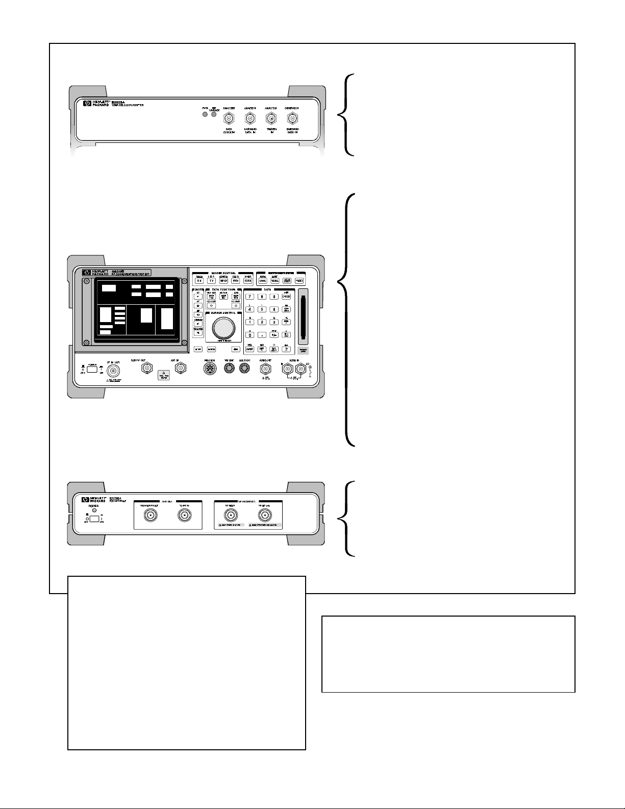
HP 8920B front and rear panels
10
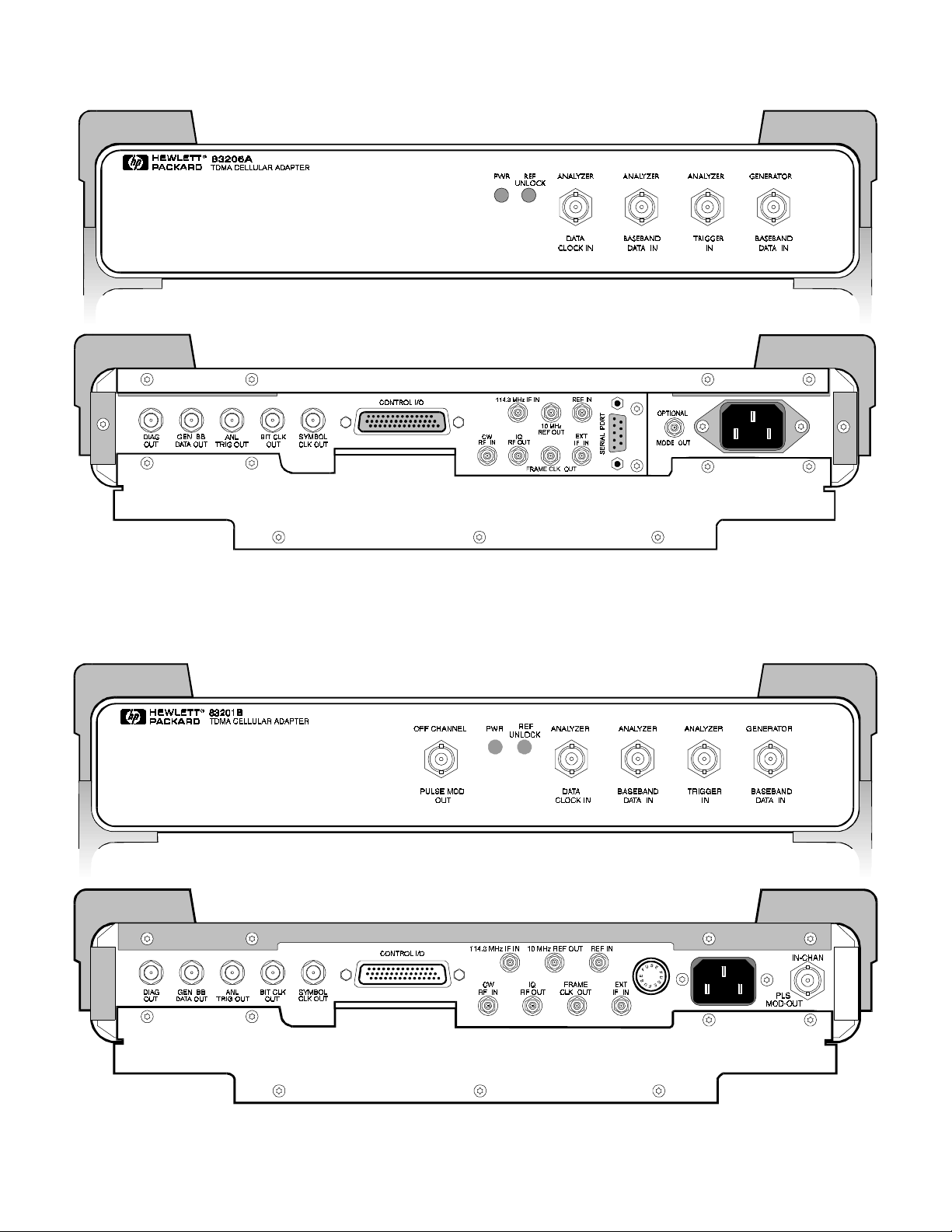
HP 83206A front and rear panels
HP 83201B front and rear panels
11

HP 83236A front and rear panels
H
For additional information, refer to the following literature:
• Brochure: literature number ........................ 5965-1571E
• Configuration Guide: literature number .... 5965-1572E
• Price List: literature number ....................... 5965-1574EUS
For more information call 1-800-452-4844
or 1-303-452-4844 or via the Web through
Access HP at http:/www.hp.com
ãã
ã 1996 Hewlett-Packard Co.
ãã
Data subject to change
Printed in U.S.A. 6/96
5965-1573E
 Loading...