


HP 8920B RF Communications Test Set
HP-IB Programmer’s Guide
SCREEN CONT ROL
POWE
OF O
!
MAX POWER
!
ANT INDUPLEX OUTRF IN/O U T
MAX POWER 200
USER
ASSIG
RELEA
SHIFT
k1’
REF
INCR
k1
k2’
k2
k3’
k3
k4
k5
CANC E
MIC/
CONFIHELPMSSG HOLD PRINT
DUPLETXRX PREV TESTS
DATA FUNCTIONS
METER
INCR
LO HI
CURSOR CON-
PUSH TO
AVG
INCR
ON/OFF
ADRS
LOCAL
789
456
123
0
YES
NO
AUDIO SQUELCVOL-
MAX
!
Firmware Versions: HP 8920B B.05.00 and above
INSTRUMENT STATE
SAVE
MEAS
RECAL
DATA
ENTER
dB
GHz
%
MHz
s
kHz
_
+
Hzms% Ωppm
AUDIO IN
!
PRESE
MEMO
LOHI
MAX
HP Part No. 08920-90222
Printed in U. S. A.
September 1997
Rev. B
1

Copyright © Hewlett-Packard Company 1995
Notice Information containe d in this document is subject to change without notic e .
All Rights Reserved. Reproduction, adaptation, or translation without prior
written permission is pr ohibited, except as allowed under the copyright laws.
This material may be reproduced by or for the U.S. Gover nment pursuant to
the Copyright License under the cla use at DFARS 52.227-7013 (APR 1988).
Hewlet t-Packard Company
Learning Products Department
24001 E. Mission
Liberty Lake, WA 99019-9599
U.S.A.
2

Manufacturer’s
Declaration
This statement is provide d to comply with the requirements of
the German Sound Emission Directive, from 18 January 1991.
This product has a sound pressure emission (at the operator
position) < 70 dB(A).
• Sound Pressure Lp < 70 dB(A).
• At Operator Position.
• Normal Operation.
• According to ISO 7779:1988/EN 27779:1991 (Type Test).
Herstellerbescheinigu
ng
Diese Information ste ht im Zusammenh ang mit den Anforderungen der
Maschinenlärminformationsverordnung vom 18 Januar 1991.
• Schalldruckpegel Lp < 70 dB(A).
• Am Arbeitsplatz.
• Normaler Betrieb.
• Nach ISO 7779:1988/EN 27779: 1991 (Typprüfung).
3

Safety Considerations GENERAL
This product and related document at ion must be reviewed for familiarizat ion
with safety markings and instr uctions before operation.
This product is a Safety Class I instrument (provided with a protective earth
terminal).
SAFETY EARTH GROUND
A uninterruptible safety earth ground must be provided from the main power
source to the product input wiring terminals, power cord, or supplied power
cord set.
CHASSIS GROUND TERMINAL
To prevent a potential shock hazard, always connect the rear-panel chassis
ground terminal to earth ground when operating this instrument from a dc
power source.
SAFETY SYMBOLS
WARNING
CAUTION
!
Indicates inst rument damage can occur if indicated operating limits are
exceeded.
Indicates hazar dous voltages.
Indicates earth (g rou nd) terminal
A WARNING note denotes a hazard. It calls atte ntion to a proc edure, practice, or
the like, which, if not correctly performed or adhered to, could result in personal
injury. Do not proceed beyond a WARNING sign until the indicated conditions
are fully understood and met.
A CAUTION note denotes a hazard. It calls attention to an operation
procedure, practice, or the like, which, if not correctly performed or
adhered to, could result in damage to or destruction of part or all of the
product. Do not proceed beyond an CAUTION note until the indicated
conditions are fully unde rstood and met.
4

Safety Considerations for this Instrument
WARNING: This product is a Safety Class 1 instrument (provided with a protective earthing ground
incorporate d in the power cord) The mains plug shall only be inserted in a socket outlet
provided with a protective earth contact. Any interruption of the protective conductor
inside or outside of the product is likely to make the product dangerous. Intentional
interruption is prohibited.
Whenever it is li kely that the protection has been impaired, the instrument must
be made inoperati ve and be secured against an y unintended operation.
If this instru ment is to be energized via an au totransformer (for voltage
reduction), make sure the common terminal is connected to the earth term inal of
the power source.
If this product is not used as specified, the protection provided by the equipm ent
could be impaired. This product must be used in a norm al condition (in which al l
means for proctection are intact) only.
No operator service able parts in this product. Refer servicing to qua lified
personnel. To pre vent electrical shock, do not remove covers.
Servicing instructions are for use by quali fied personnel only. To a void electrical
shock, do not perform any servicing unless you are qualified to do so.
The opening of covers or removal of parts is likely to expose dangerous
voltages. Dis connect the product from all voltage sources while it is being
opened.
Adjustments described in the manual are performed with power supplied to the
instrument whil e protec tive c overs ar e removed. Energy avai la ble at many points
may, if contacted, result in personal injury.
The power cord is connecte d to internal capac itors that my remain live for
5 seconds after disconnecting the plug from its power supply.
For continued protection against fire hazard, replace th e line fuse(s) only with
250 V fuse(s) or the same current rating and type (for example, normal blow or
time delay). Do not use repa ired fuses or short circuited fuseholders .
CAUTION: Always use the three-prong ac power cord supplied with this product. Failure to
ensure adequat e earth grounding by not using this cord may cause product
damage.
This product has autoranging line vol tage input, be sure th e s upply voltage is
within th e s p ec if ied rang e .
5

CERTIFICATION Hewlett-Packard Company certifies that this product met its published
specifications at the time of shipment from the factory. Hewlett-Packard
further certif ies that i ts c alibration measu rements are traceable to the Unite d
States National Institute of Standards and Technology, to the extent allowed
by the Institute’s ca libration facility, and to the calibration facilities of other
International Standards Organization members
WARRANTY This Hewlett-Packar d instr ument product in warranted against defects in
material and workmanship for a period of one year from date of shipment.
During the warranty peri od, Hewlett-Packard Company will at its option,
either repair or replace products which prove to be defective.
For warranty service or repair , this product must be returned to a service
facility desi gnated by HP. Buyer shal l prepay shippi ng charges to HP and HP
shall pay s hipping c harges, dut ies, and taxe s for pr oducts returne d t o HP fro m
another country.
HP warrants that it s software and firmware designa te d by HP for use with an
instrument will exec ute its progr amming instr uctio ns when properly inst all ed
on that instrument. HP does not warrant tha t the operation of the instrument,
or software, or fir mw ar e w ill be un int er ru pte d or erro r fre e.
LIMITATION OF
WARRANTY
EXCLUSIVE
REMEDIES
The foregoing warranty shall not apply to defects resulting from improper or
inadequate maintena nce by Buyer, Buyer-supplied software or inte rfacing,
unauthorized modification or misuse, operation outside of the environmental
specifications for the product, or improper site preparation or maintenance.
NO OTHER WARRANTY IS EXPRESSED OR IMPLIED. HP
SPECIFICALLY DISCLAIMS THE IMPLIED WARRANTIES OF
MERCHANTABILITY AND FITNESS FOR A PARTIDCULAR
PURPOSE.
THE REMEDIES PROVIDED HEREIN ARE BUYER’S SOLE AND
EXCLUSIVE REMEDIES. HP SHALL NOT BE LIABLE FOR ANY
DIRECT, INDIRECT, SPECIAL, INCIDENTAL, OR CONSEQUENTIAL
DAMAGES, WHETHER BASE ON CONTRACT, TORT, OR ANY
OTHER LEGAL THEORY.
ASSISTANCE Product maintenance agreements and other customer assistanc e agreements
are available for Hewle tt-Packard products. For any assistanc e, contact your
nearest Hewlett-Packard Sales and Service Office.
6

DECLARATION OF CO NF ORMITY
Manuf ac tu r er ’ s N a m e : Hewl ett-Pack ar d Co mpany
Manufacturer’s Address: Spokane Division
24001 E. Mission Ave.
Liberty Lake, WA 99019-9599
Declares that the product(s):
Product Name: RF Communications Test Set
Model Number(s): HP 8920A, 8920B
Product Options: All
Conforms to the following product specifications.
Safety: HD 401/IEC 348
EMC: EN 55011 (1991) /CISPR 11 (1990): ‘Group 1, Class A
EMC: EN 50082-1 (1992) /IEC 801-2 (1991): 4 kV CD, 8 kv AD
/IEC 801-3 (1991): 3 V/m
/IEC 801-4 (1991): 1k V Power Lines
0.5 kV Signal Lines
Supplementary Information:
The product herewith complies with the re quirements of the Low Voltage Directive
73/23/EEC an d EMC Directive 89/336/EEC.
Spokane,
Washington
Date Vince Roland, SKD Quality Manager
Europe an Co n t ac t: Yo u r local Hewlet t- P a ck a r d S al e s and S er v i ce Of fice or HewlettPackard GmbH. Dept. ZQ/S tandards Europe, Herrenberger StarBe 130, D- 7030
Boblingen (Fax: +49-7031-14-3143).
7

In this Book Chapter 1, Using HP-IB, describes the general guidelines for using HP-IB and how
to prepare the Test Set for HP-IB usage. This chapter includes example programs for
controlling the basic functions of the Test Set.
Chapter 2, HP-IB Command Guidelines, conta ins information about se quential
and overlapped commands, command syntax, units of measure, and measurement
stat es. A shor t exampl e program is also presented to familiarize the user with remo te
operation of the Test Set.
Chapter 3, HP-IB Commands, contains command syntax diagrams, equivalent
front-pane l key commands, IEEE 488.2 Common Commands and triggering
commands.
Chapter 4, Advanced Operations, includes information abou t increasing
measurement throughput, status report ing, error reporting, servi ce requests,
instrument initializati on, and passing control .
Chapter 5, Memory Cards/Mass Storage, describes the types of mass storage
(RAM disk, ROM disk, ext ernal disk drives, SRAM cards, and ROM ca rds) and the
file system formats (DOS, LIF) available in the Test Set.
Chapter 6, IBASIC Controller, describes how to develop Instrument BASIC
(IBASIC) progr am s for use on the Test Set’s built -in IBAS IC Controller. Topics
discus sed are: interfacing to the IBASIC Con troller u sing the serial p o rts, over view
of the three program development methods, entering and editing IBASIC programs,
program control usi ng the PROGram Subsystem, and an introduction to writ ing
programs for the TESTS subsystem.
Chapter 7, Programming the Call Proce ssing Subsystem, describes how to
control the Te st Set’s Call Proces sing Subsystem usi ng the Call Processi ng
Subsys tem’s remo t e us er in te r f ac e . Top i cs d iscussed ar e : ac ce s si ng th e C all
Processing Subs yst em screens, handling error messa ges, controlling program flow
using the Call Pr oce ssing Status Register Group, and how to query data messages
received from the mobile station. Example programs are provide d sho wing how to
control the Cal l P rocessing Subsystem using service request s and register polling.
Error Messages describes the Text Only HP-IB Errors and the Numbered HP-IB
Errors. This section als o descr ibe s other type s of error messag es tha t the Test Set
displays and where to find more information about those types of error messages.
8

Trademark
Acknowledgements
Microsoft ®, Microsoft® Windows, and MS-DOS® are registered
trademarks of Microsoft Co rpo ration.
ProComm® is a registered tra demark of DATASTORM TECHNOLOGIES,
INC.
Conventions Used In
This Manual
The generic abbreviation "PC" is used to represent computers compatible with the
IBM personal computer (PC) running the MS-DOS operating system.
The term "workstation" is used to represent HP 9000 Series 200/300 System
Controllers.
The acronym IBASI C is u sed throug hout thi s manual t o re fer to Ins trument B ASIC, a
subset of the Hewlett-Pack ard Rocky Mounta in BASIC programming language. The
term IBASIC Controller refers to the Test Set’s built-in IBASIC Controlle r.
A field on the Test Set’s display is repre se nted in the following manner:
AF Anl In.
A front-panel keycap is represented in the following manner: [TESTS].
When keys are pressed one-at-a-time, they are separated by commas. For
example, [SHIFT], [TESTS] means to press and rele ase the [SHIFT] key, then
press and release the [TESTS] key.
When keys are pressed simultaneously, they are connected by a plus sign, +.
For example, [Alt]+[ P ] means to hold down the [Alt] key and press [ P ].
Definition of Test Set The generic term "Test Set" is used inte rcha ngeably in the manual for the
HP 8920B.
9

10

Contents
1 Using HP-IB
Overview of the Test Set 18
Getting Started 26
Remote Operation 39
Addressing 41
IEEE 488.1 Remote Interface Messag e Capabilities 42
Remote/Local Modes 45
2 Methods For Reading Measurement Results
Background 50
HP BASIC ‘ON TIMEOUT’ Example Program 52
HP BASIC ‘MAV’ Example Program 56
3 HP-IB Command Guidelines
Sequential and Overlapped Commands 62
Guidelines for Operation 63
4 HP-IB Commands
HP-IB Syntax Diagrams 86
Adjacent Channel Power (ACP) 89
AF Analyzer 91
11

Contents
AF Generator 1 94
AF Generator 2 Pre-Modulation Filt ers 95
AF Generator 2/Encoder 96
Configure, I/O Configure 111
Call Processing 117
Decoder 157
Display 161
Measure 163
Oscilloscope 170
Program 175
Save/Rec al l Reg ist ers 176
RF Analyzer 177
RF Generator 179
Radio Interface 180
Spectrum Analyzer 181
HP-IB Only Co m ma n ds 183
Status 184
System 185
Tests 186
Trigger 189
12

Contents
Integer Number Setting Synt ax 190
Real Number Setting Syntax 191
Multiple Real Number Setting Syntax 192
Number Measurement Syntax 193
Multiple Number Measurement Synta x 195
Equivalent Front-Panel Key Commands 196
IEEE 488.2 Common Commands 224
Common Command Descriptions 225
Triggering Measuremen ts 243
5 Advanced Operation s
Increasing Measurement Throughput 252
Status Reporting 260
HP-IB Service Requests 311
Instrument Initialization 321
Passing Control 334
6 Memory Cards/Mass Storage
Default File System 346
Mass Storage Device Overview 348
13

Contents
Default Mass Storage Locations 355
Mass Storage Access 357
DOS and LIF File System Considerations 358
Using the ROM Disk 364
Using Memo ry Cards 365
Backing Up Procedure and Library Files 371
Copying Files Using IBASIC Commands 372
Using RAM Disk 374
Using External Disk Drives 376
7 IBASIC Controller
Introduction 378
The IBASIC Controller Screen 379
Important Notes for Program Development 381
Program Development 382
Interfacing to the IBASIC Controller using Serial Ports 384
Choosing Your Development Method 398
Method #1. Progr am Devel opment on a n External BASIC Language
Computer 400
Method #2. Developing Progr ams on th e Test Set Using the IBASIC
EDIT Mode 408
14

Contents
Method #3. Developing Programs Using Word Processor on a PC
(Least Preferred) 4 1 3
Uploading Programs from the Test Set to a PC 420
Serial I/O from IBASIC Programs 421
PROGram Subsystem 424
The TESTS Subsystem 452
8 Programming The Call Processing Subsystem
Description of the Call Proc ess ing Subsystem’s Remote User
Interface 460
Using the Call Processing Subsystem’s Remote User Interface 464
Programming The CALL CONTROL Screen 474
Programming The AUTHENTICATION Screen 510
Programming The CALL DATA Screen 519
CALL DATA Screen Message Field Descriptions 525
Programming The CALL BIT Screen 546
CALL BIT Screen Message Field Descriptions 561
Programming The ANALOG MEAS Screen 612
Programming The CALL CONFIGURE Screen 620
Example Programs 624
15

Contents
9 Error Messages
Index 673
16

1
Using HP-IB
17

Chapter 1, Using HP-IB
Overview of the Test Set
Overview of the Test Set
The Test Set combines up to 22 separate test instruments and an Instrument
BASIC (IBASIC) Controller into one pac kag e. All of the Test Set’s functions can
be automatically contr olled through application programs running on the built-in
IBASIC Controller or on an external controller connected through HP-IB.
Developing programs for the Test Set is simplified if the programmer has a basic
understanding of how the Test Set operates. An overview of the Test Set’s
operation is best presented in terms of how information flows through the unit.
The simplified block di agrams shown in
depict how instrument cont rol information and measurement result inf ormat ion
are routed among the Test Se t’s ins truments, ins trument contr ol hardware, built- in
IBASIC controller, and other components.
figure 1 on page 2 4 and figure 2 on page 25
The Test Set has two operating modes: Manual Control mode and Automatic
Control mode. In Manual Control mode the Test Set’ s operation is controlled
through the front panel keypa d/r otary knob. There are two Automatic Control
modes: Internal and External. In Internal Automatic Control mode the Test Set’s
operation is cont rolled by an application pro gram running on the built-in IBASIC
Controller. In External Automatic Control mode the Test Set’s operation is
controlled by an external controller connected to the Test Set through the HP-IB
interface.
18

Manual Control Mode
The Test Set’s primary instr uments a re shown on the left side of figure 1 . There
are two classes of instruments in the Test Set: signal analyzers (RF Analyzer , AF
Analyzer, Oscilloscope, Spectrum Analyzer, Signaling Decoder) and signal
sources (RF Generator, AF Generator #1, AF Genera tor #2/Signaling Encoder).
The Test Set’s measurement capability can be extended by adding application
specific “top boxes” such as the HP 83201A Dual Mode Cellular Adapter.
Since so many instruments are integrated into the Test Set, it is not feasible to
have an actual “front panel” for each instrument. Therefore, each instrument’s
front panel is maintained in firmware and is displayed on the CRT whenever the
instrument is select ed. Only one instrument front panel can be displaye d on the
CRT at any given time (up to four measurement results can be displa yed
simultaneously if desired). Just as with stand alone instruments, instrument front
panels in the Test Set can contain instrument setting information, measurement
result(s), or data input from the DUT.
Chapter 1, Using HP-IB
Overview of the Test Set
Using the Test Set in Manual Control mode is very analogous to using a set of
bench or rack-mounted test equipme nt. To obta in a measurement result with a
bench or racked system, the des ired measurement must be “active. ” For exa mple,
if an RF power meter is in the bench or racked system and the user wishes to
measure the power of an R F carrie r they m ust turn the po wer met er on, a nd l ook at
the front panel to see the measurement result. Other instruments in the system
may be turned off but this would not prevent the operator from measuring the RF
power.
Conceptually, the same is tr ue for the Test Set. In orde r to make a measur ement or
input data from a DUT, the desired measurement field or data field must be
“active.” This is done by using the front panel keypad/rotary knob to select the
instrument whose front panel contains the desired measurement or data field and
making sure that the desired measurement or data field is turned ON.
Figure 1 shows that instrument selection is handled by the To Screen control
hardware which routes the selected instrument’s front panel to the CRT for
display. Once an instrument’s front panel is displayed on the CRT, the user can
manipulate the in strument set tings, s uch as turning a specif ic measur ement or da ta
field on or off, using the keypad/rotary knob.
Figure 1 also shows that instrument
setup is handled by the Instrument Control hardware which routes setup
information from the front panel to the individual instruments .
An HP-IB/RS-232/Par allel Printer interface capability is available in the Test Set.
In Manual Control mode this provides the capability of connecting an external
HP-IB, serial, or parallel printer to the Test Set so that display screens can be
printed.
19

Chapter 1, Using HP-IB
Overview of the Test Set
Internal Automatic Control Mode
In Internal Automatic Control mode the Test Set’s operation is controlled by an
application program running on the built-in Instrument BASIC (IBASIC)
Controller. The built-in controller runs programs written in IBASIC, a subset of
the Hewlett-Packard BASI C programming la nguage used on the HP 9000 Series
200/300 System Controlle rs. IBASIC is the only programming language
supported on the built-in IBASIC Controller.
Similarities Between the Test Set’s IBASIC Controller and Other Single-Tasking
Controllers
The architect ure of the I BASIC Contr oller is s imila r to tha t of oth er sin gle-tas king
instrumentati on controllers. Only one program can be run on the IBASIC
Controller at any given time. The program is loaded into RAM memory from
some type of ma ss storage device. Fiv e types of mass sto rage d ev ices are
available to the Test Set: SRAM memory cards, ROM memory cards, exter nal
disk drives con nect e d to th e HP -IB int erfa ce, internal RAM disc, and internal
ROM disc. Three types of interfaces are available for connecting to external
instruments and equipment: HP-IB, RS-232, and 16-bit parallel (available as Opt
020 Radio Int erfa ce Card).
Figure 2 shows how infor mati on is routed in side the Test S et when i t is in Int ernal
Automatic Control mode. In Manual Control mode certain Test Set resources are
dedicated to manual operation. These resources are switched to the IBASIC
Controller when an IBASIC program i s running. These incl ude the serial i nterface
at select code 9, the HP-IB interfac e at select cod e 7, the p aral lel pr inter i n terface
at select code 15, and the CRT. In Manual Control mode, fron t panel inf ormation
(instrument settings, measurement results, data input from the DUT) is routed to
the CRT through the To Screen control hardware. In Internal Automatic Control
mode the measurement results and data input from the DUT are routed to the
IBASIC Co ntr oll er thr o ugh a de d icat ed HP-IB interface. Also, in Internal
Automatic Control mode, the CRT is dedicat ed to the IBASIC Controller for
program and graphics displ ay. This mean s instrument front panels cannot be
displayed on the CRT when an IBASIC program is running.
20

Chapter 1, Using HP-IB
Overview of the Test Set
Differences Between the Test Set’s IBASIC Controller and Other Single-Tasking
Controllers
The IBASIC Controller is unlike othe r single tasking instrumentation co ntrollers
in several ways. First, it does not have a keyboard. This imposes some limitati ons
on creating and editing IBASIC programs directly on the Test Set. In Internal
Automatic Control mode a “virtual” key board is available in firmware which
allows the operator to ente r alpha numeric data into a dedicated input fiel d using
the rotary knob. This is not the recommended pr ogramming mode for the IBASIC
Controller. This feature is provided to allow user access to IBASIC programs for
short edits or troubleshooting. Several programming modes for developing
IBASIC programs to run on the internal IBASIC Controller are discussed in this
manual.
Secondly, the I BASIC Contr oller ha s a dedic ate d HP-IB interface, select code 8 in
figure 2 , for communicating with the internal instrumen ts of the Tes t Set. This
HP-IB interface is only available to the IBASIC Controller. There is no external
connector for this HP-IB int erface. No external instruments may be added to this
HP-IB interface. The HP-IB interface, select code 7 in
figure 2 , is used to
interface the Test Set to external instruments or to an external controller. The
dedicated HP-IB interface at select code 8 conforms to the IEEE 488.2 Standard
in all respects bu t one. T he difference being that each instrumen t on the bus does
not have a unique address. The Instrument Co ntrol Hardware determines which
instrument is being addressed through the command syntax. Refer to
"HP-IB Commands"
for a listing of the HP-IB command syntax for the Test Set.
chapte r 4 ,
21

Chapter 1, Using HP-IB
Overview of the Test Set
External Automatic Control Mode
In External Automatic Control mode the Test Set’s oper ation is controlled by an
external contr oller c onnec ted t o the Te st Set thr ough the HP-IB interface. When in
External Automati c Control mode t he Tes t Set’s int ernal conf iguratio n is the sa me
as in Manual Control Mode with two exceptions:
1. Configura ti on and setup comm ands are rec eived th rough the ext ernal HP-IB int erfac e,
select code 7, rather than from the front-panel keypad/ro tary knob.
2. The MEASure command is used to obtain measurement results and DUT data t hrough
the external HP-IB interface.
Figure 1 on page 24
shows how information i s routed insi de t he Test Set in Manua l
Control mode. F igure 1 also shows t hat certain Te st Set re sources are dedicated to
the IBASIC Controller (Memory Card, ROM disk, Serial Interface #10) and are
not directly accessible to the user in Manual Control Mode. In addition, figure 1
shows that Serial Interface #9 and Parallel Printer Interfa ce #15 are accessible as
write-only inte rfaces for print ing in Manual Control mode. These sa me condit ions
are true when in External Automatic Control mode. If the user wished to access
these resources from an exter nal control ler, an IBASIC progra m would have to be
run on the Test Set from the external controller.
22

Writing programs for the Test Set
One of the design goals for automatic control of the Test Set was that it operate
the same way programmatically as it does manually. This is a key point to
remember when developing progr ams for the Test Set. The benefit of this
approach is that to automate a part ic ular task, one need only figure out how to do
the task manually and then duplic at e the same process in software. This has
several implications when designing and writing programs for the Test Set:
1. In Manu al Co ntrol mod e a me asurement must be “a cti ve ” in or d er to ob t ain a meas ur e-
ment result or input data from the DUT. From a programming perspective this means
that before attemptin g to read a m easurement res ult or to input data from the DUT, the
desired screen for the measurement result or data field mu st be s elected using the DISPlay command and the field must be in the ON state.
2. In Manual Con trol mode instrument configu ration informat ion is not routed throu gh the
To Screen control hardware block. From a programming perspective this mea ns that
configuration in form ation c an be sent to a ny desired i nstrum ent with out having to firs t
select th e in st r u ment’s fron t p an el wi t h th e DI SP l ay co m m an d .
Chapter 1, Using HP-IB
Overview of the Test Set
Keeping these points in mind durin g program development will minimize
program development time and reduc e proble ms encountered when running the
program.
23

Chapter 1, Using HP-IB
Overview of the Test Set
#9
CRT
FRONT PANEL
CONTROL
TO SCREEN
HARDWARE
KEYPAD/
ROTARY KNOB
FRONT
PANEL
INFORMATION
MEMORY CARD
IBASIC
INST RUMENT CON-
HP - IB
ROM DISK
CONTROLLER
#8
TROL HARDWARE
INSTRUMENT
#10
SERIAL I/F
SERIAL I/F
PARALLEL
SETUP
INFORMATION
#7
#15
HP - IB
PRINTER
RF GEN
AF GEN #1
MEASUREMENT RESULTS AND DUT DATA
GEN
AF GEN #2
FUNCTION
ENCODER
SIGNALING
AF ANALYZER
SPECTRUM
ANALYZER
OSCILLOSCOPE
RF ANALYZER
Figure 1 Manual Control Mode
24
TOP
BOXES
DECODER
SIGNALING

Chapter 1, Using HP-IB
Overview of the Test Set
#9
CRT
KEYPAD/
FRONT PANEL
CONTROL
TO SCREEN
HARDWARE
ROTARY KNOB
FRONT
PANEL
INFORMATION
MEMORY CARD
IBASIC
INSTRU M ENT CON-
CONTROLLER
HP - IB
TROL HARDWARE
ROM DISK
#8
INSTRUMENT
#10
SERIAL I/F
SETUP
INFORMATION
PARALLEL
SERIAL I/F
#7
#15
HP - IB
PRINTER
RF GEN
AF GEN #1
MEASUREMENT RESULTS AND DUT DATA
GEN
AF GEN #2
FUNCTION
ENCODER
SIGNALING
AF ANALYZER
Figure 2 Internal Automatic Cont rol Mode
TOP
BOXES
SPEC TRUM
ANALYZER
OSCILLOSCOPE
DECODER
SIGNALING
RF ANALYZER
25

Chapter 1, Using HP-IB
Getting Started
Getting Started
What is HP-IB?
The Hewlett-Packa rd Inte rface B us (HP-IB) i s Hewlet t-Pac kard’s i mplement ation
of the IEEE 488.1-1987 Standard Digital Interface for Programmable
Instrumentation. Incorporation of the HP-IB into the Test Set pr ovides several
valuable capabil ities:
• Programs running in the Test Set’s IBASIC Controller can control all the Test Set’s
functions using its internal HP-IB. This capability provides a single-instrument automated test system. (Th e HP 11807 Radio Test Software utilizes this capability.)
• Programs running in the Test Set’s IBASIC Controller can control other instruments
connected to the external HP- I B.
• An external controller, connected to the external HP-IB, can re motely cont r ol the Test
Set.
• An HP-IB prin te r, conn ec ted to the e xte rnal HP -IB , can be used to print t est resul ts and
full screen images.
26

HP-IB Information Provided in This Man ual
What Is Explained
How to configure the Test Set for HP-IB ope ration
• How to make an instrument sett ing over HP-IB
• How to read-back instrument settings over HP-IB
• How to make measurements over HP-IB
• How to co n nect exte r na l P C s , te r m i n als or contr o llers to the Test Set
• HP-IB command syntax for the Test Set
• IBASIC program development
• IBASIC program transfer over HP-IB
Chapter 1, Using HP-IB
Getting Started
• Various advance d f unction s s uch as, i ncreasi ng me asure ment throughpu t, sta tus reporting, error reporting, pass control, and so forth
What Is Not Explained
• HP-IB (IEEE 488.1, 488.2) theory of operation
• HP-IB electrical specifications
• HP-IB connector pin functions
1
1
1
• IBASIC programming (oth er than general guidel ines related to HP-IB)2
1. Refer to the Tutor i a l D e scripti on of the Hewlett- P ackard I n terfac e Bu s
(HP P/N 5952-0156) for detaile d information on HP-IB theory and operat ion.
2. Refer to the HP Instrument BASIC Users Handbook Version 2.0 (HP P/N E2083-
90005) for more information on the IBASIC Version 2.0 language.
27

Chapter 1, Using HP-IB
Getting Started
General HP-IB Programming Guidelines
The following guidelines should be consider ed when de veloping programs which
control the Test Set through HP-I B:
• Guideline #1. Avoid using the TX TEST and RX TEST screens.
The RX TEST and TX TEST screens are specifi cally designed for manual testing of
land mobile FM radios and , when displayed, automat ica lly configure six “priority”
fields in th e Test Set for this purpose. The pr iority fields and their preset values ar e
listed in table 1 on page 29. When the TX TEST screen or the RX TEST screen is dis-
played, certain priorit y fields are hidden and are not settable. The priority field s which
are hidden are listed in table 1 on page 29.
When the TX TEST screen or the RX TEST screen is displayed, any HP-IB commands
sent to the Test Set to change the value of a hidden pri ority field are ignored. Hidden priority fields on the TX TEST or RX TEST screens are not settable manually or programmatically.
Displaying eith er of the se scree ns aut omati call y re-conf igur es the 6 “prio rit y” fiel ds as
follows:
1. When ente rin g th e R X TEST screen,
a. the RF Generator’s Amplitude field, the AFGen1 To field and the AF An-
alyzer’s measurement fi eld (measurement displayed in upper, right portion of
CRT display) are
• set to their preset values upon entering the screen for the first time since
power-up, OR
• set to their preset values if the PRESET key is selected, OR
• set to th e la s t set t in g m ad e w h il e in the screen
b. the RF Generator Amplitude field and the AFGen1 To field are
• set to their preset values whenever entering the screen, OR
• set to th ei r pr ese t v al u es if th e PR ES ET key is sel ected
28

Chapter 1, Using HP-IB
Getting Started
2. When ente rin g th e TX TEST screen ,
a. The AF Anl In field, the De-Emphasis field, the Detector field a nd the
AF Analyzer Measuremen t field (measurement di splayed in upper, right portion
of CRT display) are,
• set to their preset values upon entering the screen for the first time since
power-up, OR
• set to their preset values if the PRESET key is selected, OR
• set to th e la s t set t in g m ad e w h il e in the screen
b. The AF Analyzer AF Anl In, De-Emphasis and Detector fields are,
• set to their preset values whenever entering the screen, OR
• set to th ei r pr ese t v al u es if th e PR ES ET key is sel ected
Table 1 RX TEST Screen and TX TEST Screen Priority Field Preset Values
Priority
Field
RF Gen
RX TEST
Screen Preset
Value
−80 dBm No Off Yes
Field Hidden
On RX TEST
Screen
TX TEST
Screen Preset
Value
Amplitude
AFGen1 To FM No Audio Out Yes
AF Anl In Audio In Yes FM Demod No
Detector RMS Yes Pk ± Max No
De-emphasis Off Yes 750 µsNo
AF Analyzer
SINAD No Audio Freq No
Measurement
Field
Hidden On
TX TEST
Screen
29

Chapter 1, Using HP-IB
Getting Started
• Guideline #2. When developing programs to make measurements always follow this
recommended sequence:
1. Bring t he Test Set to it s prese t stat e usi ng the front -pan el PRESET key. Th is ini tial
step allows you to s t art dev eloping the m easurem ent se quen ce wit h most fi elds in a
known state.
2. Make the measurement manually using the front-panel con trols of the Test Set.
Record, in sequential order, the screens select ed and the se ttings made wi thin each
scree n. The rec ord of the scr eens sele cted an d setting s made in eac h screen bec omes
the measurement procedure.
3. Record the measurement result(s).
In addition to the DISPlay com mand, the signa li ng ENCode r and DECod er requi re
further commands to display the correc t fields for ea ch signaling mode. For example, DISP ENC;:ENC:MODE 'DTMF'.
4. Develop the program using the measurement proced ure ge nerated in step 2. Be sure
to start the prog rammatic measurem ent sequenc e by bringing the Test Set to its pre set
state using the *RST Common Command. As the measurement procedure requires
changing screens, us e the DISPlay command to s elect t he des ired scr een fol lowed by
the cor re c t co mmands to set the de s ired field(s) .
When IBASIC programs are running the CRT is dedicated to the IBASIC Controller for
program and gr aphics di spla y. This means ins trume nt front p anels ar e not di spla yed on th e
CRT when an IBASIC program is running. However, the DISPlay <scre en> command
causes all setting and measurement fie lds in the <screen> to be access ible programmatically. Attempting to read from a screen that has not been made accessible by the DISPlay
comman d wil l cause
HP-IB Error:-420 Query UNTERMINATED, or
HP-IB Error: -113 Undefined header
Make sure the desired measurement is in the ON state. This is the preset state for most
measurements. However, if a previous program has set the state to OFF, the measurement
will not be available. Attempting to read from a measurement field that is not in the ON
state wil l ca us e HP-IB Error:-420 Query UNTERMINATED.
5. If the trigger mode has been changed, trigger a reading.
Triggering is se t to F ULL SETTling and REPetitive RETRiggering after receipt of the
*RST Common Command. These settings cause the Test Set to trigger itself and a sepa rate trigger command is not necessary.
30

Chapter 1, Using HP-IB
Getting Started
6. Send the MEASure query com m and to initiate a reading. This will place the mea-
sured value into the Test Set’ s Output Queue.
When making AF Analyzer SINAD, Dis tortio n, Sig nal to Noi se Ratio, AF Fr equenc y, DC
Level, or Current me as urements, the me as urement type must firs t be selected using the
SELect co mmand.
For example, MEAS:AFR:SEL'SINAD' followed by MEAS:AFR:SINAD?
7. Use the ENTER statement to transfer the measured value to a variable within the
context of the program.
The following example program illustr ates how to make settings and then take a
reading from the Test Set. This setup takes a reading from the spectrum analyzer
marker after tuning it to the RF generator’s output frequency.
Example
10 Addr=714
20 OUTPUT Addr;"*RST" !Preset to known state
30 OUTPUT Addr;"TRIG:MODE:RETR SING" !Sets single trigger
40 OUTPUT Addr;"DISP RFG" !Selects the RF Gen screen
50 OUTPUT Addr;"AFG1:FM:STAT OFF" !Turns FM OFF
60 OUTPUT Addr;"RFG:AMPL -66 DBM" !Sets RF Gen ampl to -66 dBm
70 OUTPUT Addr;"RFG:FREQ 500 MHZ" !Sets RF Gen freq to 500 MHz
80 OUTPUT Addr;"RFG:AMPL:STAT ON" !Turns RF Gen output ON
90 OUTPUT Addr;"DISP SAN"!Selects Spectrum Analyzer’s screen
100 OUTPUT Addr;"SAN:CRF 500 MHZ" !Center Frequency 500 MHz
110 ! -------------------MEASUREMENT SEQUENCE------------------120 OUTPUT Addr;"TRIG" !Triggers reading
130 OUTPUT Addr;"MEAS:SAN:MARK:LEV?" !Query of Spectrum
140 !Analyzer’s marker level
150 ENTER Addr;Lvl !Places measured value in variable Lvl
160 DISP Lvl!Displays value of Lvl
170 END
The RF Generator’s output por t and the Spectrum Analyz er’s input port are pres et
to the RF IN/OUT port. This allows the Spectrum Analyzer to measure the RF
Generator with no e xternal conne ction s. The Spectr um Analy zer marker is a lways
tuned to the center frequency of the Spectrum Analyzer after preset. With the RF
Generator’s o utput port and Spectrum Analyzer input port both directed to the RF
IN/OUT port, the two will internally couple with 46 dB of gain, giving a measured
value of approximate ly -20 dBm. While not a nor mal mode of ope ration th is setup
is convenient for demonstr ation since no external cables are required. This also
illustrates the value of starting from the preset state sinc e fewer programming
commands are required.
31

Chapter 1, Using HP-IB
Getting Started
• Guideline #3. Avoid program hangs.
If the program stops or “ hangs up” whe n trying t o ENTER a mea sured value , it i s most
likely that the desired measurement field is not available. There are several reasons
that can happen:
1. The screen where the measurement field is located has not been DISPlayed before
querying the measurement field.
2. The measurement is no t turned ON.
3. The squelc h control is set too high. If a measure ment is turned ON but is n ot avail-
able due to the Squelch setting, the m easurement field contains four dashes
(- - - -). Thi s is a val id state. The Test Set is waiting for a sign al of suff icient str ength
to unsqu e lch the recei v er be f o re m ak i n g a measurem en t . If a m ea s u rement fiel d
which is squelched is queried the Test Set will wait indefinitely for the receiver to
unsquelch and return a measured value.
4. The RF Anal yzer’s In put Port i s set t o ANT (an tenna) whil e tryin g to read T X pow-
er. TX powe r i s not measu rable with the Input Port set t o ANT. The T X power m easurement field will display four dashes (- - - -) indicating the measurement is
unavailable.
5. The inpu t signal to the Tes t Set i s very unsta ble causin g the Tes t Set to c ontinuou sly
autorange. This condition will be apparent if an attempt is made to make the measurement manually.
6. Trigger mode has been set to single trigger (TRIG:MODE:RETRig SINGle) and a
new measurement cycle has not been triggered before attempting to read the measured value.
7. The program is att em pting to make an FM deviation or AM depth meas urem ent
while in the RX TEST screen. FM or AM measurements are not available in the RX
TEST screen. FM or AM measurements are made from the AF Analyzer screen by
setting the AF Anl In field to FM or AM Demod.
32

Chapter 1, Using HP-IB
Getting Started
• Guideline #4. Use single quotes and spaces properly.
The syntax diagr a ms in chapter 4, "HP-IB Commands," show where single quotes
are need e d an d whe r e sp aces are need ed .
Example
OUTPU T 714 ;" DI SP<space >A FAN"
OUTPU T 714 ;" AF AN:DEMP< sp ace>’Off’ "
Improper use of single quotes and spaces will cause,
HP-IB Error:-103 Invalid Separator
• Guideline #5. Ensure th at sett ab le fie lds ar e ac tiv e b y us ing the STAT e ON com man d.
When making settings to fields that can be turned OF F with the STATe ON/OF F com-
mand (refer to the Chapter 4, "HP-IB Commands"), make sure the STATe is ON if
the program uses that field. Note that if the STATe is OFF, just setting a numeric value
in the field will not change the STATe to ON. This is different than front-panel operation whereby the pr ocess of selecting the field and entering a value automatica lly sets
the STATe to ON. Programmatically, fields must be explicitly set to the ON state if
they are in the OFF state.
For example, the fol lowing comm and line would set a new AMPS ENCoder SAT t one
deviation and then turn on the SAT tone (note the use of the ; to back up one level in
the command hier archy so that more than one command can b e ex ecuted in a sing l e
line):
Example
OUTPUT 714;"ENC:AMPS:SAT:FM 2.1 KHZ;FM:STAT ON"
To just turn on the SAT tone witho ut changing the current setting the following commands would be used:
OUTPU T 714 ;" EN C:AMPS:S AT :FM:STAT ON "
33

Chapter 1, Using HP-IB
Getting Started
• Guideline #6. Numeric values are returned in HP-IB Units or Attribute Units only.
When querying measurements or se ttings through HP-IB, the Test Set always returns
numeric values in HP-IB Units or Attribute Units, regardless of the current Display
Units setting. HP-IB Units, Attribute Units and Display Units determine the units-ofmeasure u sed for a measurement or sett in g , for exa mple, Hz, Volts, Wat ts, Amper es,
Ohms. Refer to "Specifying Units-of-Measure for Settings and Measurement
Results" on page 67 for further information.
For example, if the Test Set’ s front panel is displaying T X Frequency as 835.02 MHz,
and the field is que ried through HP-IB, the value returned will be 835020000 since the
HP-IB Units for frequency are Hz. Note that changing Displ ay Units will not change
HP-IB Units or Attribute Units. Note also that setting the value of a numeric field
through HP-IB can be done using a variety of units-of-measure. The HP-IB Units or
Attribute Units for a queried value can always be determined using the :UNITs? command or :AUNits? c ommand respectively (refer to "Number Measurement Syntax"
on page 193 or "Multiple Number Measurement Syntax" on page 195, for com-
mand syntax).
Control Annunciators
The letters and symbols at the top right c orn er of the display indicate these
conditions:
• R indicates the Test Set is in remote mode. The Test Set can be put into the remote mode
by an external con troller or by an IBAS IC program runni ng on the buil t-in IBASIC c ontroller.
• L indicates th at the Test Set has been addressed to Listen.
• T indicates th at the Test Set has been addressed to Talk.
• S indicat es that the Tes t Set has sent the Require Servic e messa ge by sett ing the Servic e
Request (SRQ) bus line true. (See "Status Reporting" on page 260.)
• C indicates that the Test Set is currently the Active Controller on the bus.
• * indicates that a n IBASIC program is running.
• ? indicates that an IBASIC program is waiting for a user response.
• - indicates that an IBASIC program is paused.
34

Preparing the Test Set For HP-IB Use
1. If other HP-IB devices are in the system, attach an HP-IB c able from the Test Set’s rear-
panel HP-IB connector to any one of the other devices in the test system.
2. Access the I/O CONFIGURE screen and perform the following steps:
a. Set the Test Set’s HP-IB address using the HP-IB Adrs field.
b. S et the Test Set’ s HP-IB Contro ller capab ility using the Mode field.
• Talk&Listen configures the Tes t S et to not be the System Controller. The Test Set
has Active Controller capability (take control/pass con trol) in this mode. Use thi s setting if the Test Set will be controlled through HP-IB from an external controller.
• Control configures the Test Set to be the System Controller. Use this setting if the
Test Set will be the only controll er on the HP-IB. Selecting the Control mode automatically make s the Test Set th e Active Contro ller.
Chapter 1, Using HP-IB
Getting Started
NOTE: Only one System Controller can be configured in an HP-IB system. Refer to "Passing
Control" on page 334 for furthe r information.
3. If an HP-IB prin ter is or wil l be c onnect ed to the Test S et’s re ar panel HP-IB c onne ctor
then,
a. access the P R I N T CO N FIGURE scr een.
b. select one of the supported HP-IB printer models using the Model field.
c. set the Printer Port field to HP-IB.
d. s et the printer address using the Printer Address field.
35

Chapter 1, Using HP-IB
Getting Started
Using the HP-IB with the Test Set’s built-in IBASIC Controller
The Test Set has two HP-IB interfaces, an internal-only HP-IB at select code 8
and an external HP-IB at select code 7. The HP-IB at select code 8 is only
available to the built- in IBASIC Controller and is used exclusively f or
communication between the IBASIC Controller and the Test Set. The HP-IB at
select code 7 serves three pur pose s:
1. It al lows the Test Set to be controlled by an external controller
2. It al lows the Test Set to print to an external HP-IB printer
3. It al lows the built-in IBASIC Controller to control external HP-IB devices
IBASIC programs running on the Test Set’s IBASIC Controller must use the
internal-only HP-IB at select code 8 to control the Test Set. IBASIC programs
would use the external HP-IB at select c ode 7 to control HP-IB devices connected
to the rear panel HP-IB connector.
NOTE: Refer to "Overview of the Test Set" on page 18 for a deta il ed ex p l an at io n o f th e Te s t S et ’ s
architecture.
When using a BASIC language Workstation with an HP-IB int erf ace at select
code 7 to control the Test Set, HP-IB commands would look like this:
Example
! This command is sent to the Test Set at address 14.
OUTPU T 714 ;" *R ST"
! This command is sent to another instrument whose address is 19.
OUTPU T 719 ;" *R ST"
When executing the same commands on the Test Set’s IBASIC Controller, the
commands would look like this:
Example
OUTPU T 814 ;" *R ST"
! Command sent to internal-only HP-IB at select code 8,
! Test Set’s address does not change
OUTPU T 719 ;" *R ST"
! Command sent to external HP-IB at select code 7,
! other instrument’s address does not change.
36

Basic Programming Examples
The following simple examples illustrate the basic approach to controlling the
Test Set through the HP-IB. The punctuation and command syntax used for these
examples is given in Chapter 4, "HP-IB Commands".
The bus address 714 used in the following BASIC language examples assumes an
HP-IB interface at select code 7, and a Test Set HP-IB address of 14. All examples
assume an external controller is being used.
To Change a Field’s Setting over HP-IB
1. Use the DI SPlay comman d to acce ss th e screen c ontain ing th e field whos e sett ing is to
be changed.
2. Make the desired setting using the proper command syntax (refer to Chapter 4, "HP-
IB Commands" for proper syntax).
The following example makes several instrument setting changes:
Chapter 1, Using HP-IB
Getting Started
Example
OUTPUT 714;"DISP RFG" !Display the RF Generator screen.
OUTPUT 714;"RFG:FREQ 850 MHZ" !Set the RF Gen Freq to 850 MHz.
OUTPUT 714;"RFG:OUTP ’DUPL’"!Set the Output Port to Duplex.
OUTPUT 714;"DISP AFAN"!Display the AF Analyzer screen.
OUTPUT 714;"AFAN:INP ’FM DEMOD’"!Set the AF Anl In to FM Demod.
To Read a Field’s Setting over HP-IB37
1. Use the DI SPlay c ommand to acce ss th e screen c ontain ing th e field whos e sett ing is to
be read.
2. Use th e Query form o f the syntax f o r that field to place the setting value into the Test
Set’s output buffer.
3. Enter the val ue into the corr ect varia ble ty pe within the progr am context ( refer to Chap-
ter 4, "HP-IB Commands", for proper variable type).
37

Chapter 1, Using HP-IB
Getting Started
The following example reads sev era l fields.
Example
OUTPUT 714;"DISP AFAN"!Display the AF Analyzer screen.
OUTPUT 714;"AFAN:INP?"!Query the AF Anl In field
ENTER 714;Af_input$ !Enter returned value into a string ariable.
OUTPUT 714;"DISP RFG"!Display the RF Generator screen
OUTPUT 714;"RFG:FREQ?"!Query the RF Gen Frequency field.
ENTER 714;Freq !Enter the returned value into a numeric variable
NOTE: When querying measure ments or se ttings throug h HP-IB, the Test Set al ways returns
numeric values in HP-IB Units or Attribute Units, re gardless of the current Display
Units setting. Refer to "HP-IB Units (UNIT s)" on page 70 and "Attribute Units
(AUNits)" on page 73 for further information.
To Make a Simple Measurement
The basic m ethod for makin g a measurement is very similar to t he method used to
read a field setting.
1. Use the DISP l ay co m ma n d to ac cess the scre en co n ta in i n g th e desired me asu r e m en t .
2. Use the MEASure form of the syntax for that measurement to place the measured value
into the Test Set’s output buffer.
3. Enter the va lue in to t he corr ec t va ria ble t ype with in t he progra m con tex t (re fe r to chap -
ter 4, "HP-IB Commands" for proper variable type).
The following example measures the power of an RF signal .
Example
!Display the RF Analyzer screen.
OUTPUT 714;"DISP RFAN"
!Measure the RF power and place result in output buffer.
OUTPU T 714 ;" ME AS:RFR:P OW? "
!Enter the measured value into a numeric variable.
ENTER 714;Tx_power
The above example i s ver y simple and i s designe d to de monstr ate the fundamenta l
procedure for obtain ing a measurement result. Many other factors must be
considered when designing a measuremen t proced ure, suc h as inst rument sett ings,
signal routing, settling time, filtering, triggering and measurement speed.
38

Remote Operation
Chapter 1, Using HP-IB
Remote Operation
The Test Set can be operated remotely through the Hewlet t-Packard I nterface Bus
(HP-IB). Except as otherwis e noted, the Test Set complies with the IEEE
488.1-1987 and IEEE 488.2-1987 Standa rds. Bus compatibility, prog ramming
and data formats are describe d in the following sections.
All front-panel f unctio ns, excep t those li sted in
table 2, are programmable thr ough
HP-IB.
Table 2 Non-Programmable Front Pa n el F unc tions
Function Comment
ON/OFF Power Switch
Volume Control Knob
Squelch Control Knob The position of the Squelch Control knob cannot be programm ed. How-
ever squelch can be programmed to either the Open or Fixed position.
Refer to the Test Set’s User’s Guide for more information.
Cursor Control Knob
SHIFT Key
CANCEL Key
YES Key
NO Key
ENTER Key
Backspace (lef t-arrow) K ey
PREV Key
HOLD ( SHIFT, PREV Keys)
PRINT ( SHIFT, TESTS Keys)
ADRS ( SHIFT, LOCAL Keys)
ASSIGN ( SHIFT, k4 Keys)
RELEASE ( SHIFT, k5 Keys)
39

Chapter 1, Using HP-IB
Remote Operation
Remote Capabilities
Conformance to the IEEE 488.1- 1987 Standard
For all IEEE 488.1 functions implemented, the Test Set adheres to the rules and
procedures as outlin ed in that Standard.
Conformance to the IEEE 488.2- 1987 Standard
For all IEEE 488.2 functions implemented, the Test Set adheres to the rules and
procedures as outlin ed in that Standard with the exception of the *OPC Common
Command. Refer to the *OPC Common Command description.
IEEE 488.1 Interface Functions
The interface functions that the Test Set implements are listed in table 3.
Table 3 Test Set IEEE 488.1 Interface Function Capabilities
Function Capability
Talker T6: No Talk Only Mode
Extended Talker T0: No Extended T alker Capability
Listener L4: No Lis te n On ly M od e
Extended Listener LE0: No Extended Listener Capability
Source Handshake SH1: Complete Capability
Acceptor Handshake AH1: Complete Capability
Remote/Local RL1: Complete Capability
Service Request SR1: Complete Capability
Parallel Poll PP0: No Parallel Poll Capability
Device Clear DC1: Complete Capability
Device Trigge r DT1: Complete Capability
Controlle r C1: System Controller
C3: Send REN
C4: Respo nd to S RQ
C11:No Pass Control to Self, No Parallel Poll
Drivers E2: Tri-S tate Drivers
40

Addressing
Factory Set Address
Extended Addressing
Chapter 1, Using HP-IB
Addressing
The Test Set’s HP-IB address is set to decimal 14 at the factory. The address can be
changed by following the instru ctions in "Setting the Test Set’ s Bus Address" on page
41
.
Extended addressi ng (se condary command) capabili ty i s not imple mented i n the Test
Set.
Multiple Addressing
Multiple addressing c apability is not implemented in the Test Set.
Setting the Test Set’s Bus Address
The Test Set’s HP-IB bus address is set using the HP-IB Adrs field which is located
on the I/O CONFIGURE screen. To set the HP-IB bus address; select the I/ O
CONFIGURE screen and position the cursor ne xt to the
address can be set from decimal 0 to 30 using the numeric DATA keys, or by
pushing and then rotating the Cursor Cont rol knob. There are no DIP switches for
setting the HP-IB bus address in the Test Set. The new setting is retained when the
Test Set is turned off.
Displayi ng t he Bus Add ress
The Test Set’s HP-IB bus address can be displayed by pressing and releasing the
SHIFT key, then the LOCAL key. The address is displayed in the upper left-hand
corner of the display screen.
HP-IB Adrs field. The
41

Chapter 1, Using HP-IB
IEEE 488.1 Remote Interface Message Capabilities
IEEE 488.1 Remote Interface Message Capabilities
The remote interface message capabili tie s of the Test Set and the associated IEEE
488.1 messages and control lines are listed in table 4.
Table 4 Test Set IEEE 488.1 Interface Message Capability
Message Type Implemented Response
IEEE
488.1
Message
Data Yes All front- panel functio ns , except thos e listed in table 2 on
page 39, are programmable. The Test Set can send status
byte, mes sa g e and setting i nf o r mation. All measuremen t
results (except dashed “- - - -” displays) and error messages are availa ble through the bus.
Remote Yes R emote programming mode is entered when the Remote
Enable (REN) bus control line is true and the Test Set is
addressed to listen. The R annuncia tor will appear in the
upper-right corner of the displ ay s creen when the Test Set
is in remote mode. All front-panel keys are disabled
(except for the LOCAL key, POWER switch, Volume
control and Squelch control knobs). When the Test Set
enters re mote m ode the o utpu t si gnal s a nd i nter nal sett ing s
remain unchanged, except that triggering is reset to the
state it was last set to in remote mode (Refer to "Trigger-
ing Measurements" on page 243).
Local Yes The Test Set returns to local mode (full front-panel con-
trol) when either the Go To Local (GTL) b u s command is
received, the fr ont-pa n el LOCAL key is pressed or the
REN line goes false. When the Test Set returns to local
mode the output signals and internal settings remain
unchanged, exce pt that triggering is reset to
TRIG:MODE:SETT FULL;RETR REP. The LOCAL key
will not funct ion if the Test Set is in the local lockout
mode.
DAB
END
MTA
MLA
OTA
REN
MLA
GTL
MLA
Local Lockout Yes Local Lockout disables all front-panel keys including the
LOCAL key. Only the System Controller or the POWER
switch can return the Test Set to local mode (front-pa nel
control).
42
LLO

IEEE 488.1 Remote Interface Message Capabilities
Table 4 Test Set IEEE 488.1 Interface Message Capability (Continued)
Message Type Implemented Response
Chapter 1, Using HP-IB
IEEE
488.1
Message
Clear Lockout/
Set Local
Yes The Test Set returns to local mode (front-pane l co ntrol)
and local lockout is clea red when the REN bus control line
goes false. When the Test S et returns to local mode the
output signals and internal settings remain unchanged,
except that triggering is set to TRIG:MODE:SETT
FULL;RETR REP.
Service Request Yes The Test Set sets t he Service Request (SRQ) bus line true
if any of the enable d conditions in the St atus Byte Register, as define d by the Se rvice Re ques t Enabl e Regist er, are
true.
Status Byte Yes The Test Set responds to a Seria l Po ll Enable (SPE) bus
command by sending an 8-bi t status byte when address ed
to talk. Bit 6 will be true, logic 1, if the Te st Set has sent
the SRQ message
Status Bit No The Test Set does not ha ve the capability to respond to a
Parallel Poll.
Clear Yes This message clears the Input Buffer and Output Queue,
clears any commands in process , puts the Test Set into the
Opera tio n Compl et e idl e stat e an d prepar es the Te s t Set to
receive new commands. The Device Clear (DC L) or
Selected Device Cle ar (SDC) bus commands
REN
SRQ
SPE
SPD
STB
MTA
PPE
PPD
PPU
PPC
IDY
DCL
SDC
MLA
• do not change any settings or stored data (except as
noted previously)
• do not interrupt front panel I/O or any Test Set
operation in progre ss (except as noted previously)
• do not change the c ontents of the Status Byte Register
(other than clea r i n g the MAV bit as a consequence of
clearin g the Output Queue).
The Test Set responds equally to DCL or SDC bus commands.
43

Chapter 1, Using HP-IB
IEEE 488.1 Remote Interface Message Capabilities
Table 4 Test Set IEEE 488.1 Interface Message Capability (Continued)
Message Type Implemented Response
IEEE
488.1
Message
Trigger Yes If in remote programming mode and addressed to listen,
the Test Set makes a triggered meas urement fol lowi ng the
GET
MLA
trigger conditions currently in effect in the instrument.
The Test Set responds equally to the Group Execute Trigger (GET) bus command or the *TRG Common Command.
Take Control Yes The Test Set begins to act as the Active Controller on the
bus.
TCT
MTA
Abort Yes The Test Set stops talking and listening IFC
44

Remote/Local Modes
Remote Mode
In Remote mode all front-panel key s are disabled (except for the LOCAL key,
POWER switch, Volume control and Squelch control). The LOCAL key is only
disabled by the Local Lockout bus command. When in Remote mode and
addressed to Listen the Test Set r espo nds to the Data, Remote, Local, Clear
(SDC), and Trigger messages. When the Test Set is in Remote mode, the
annunciator will be displayed in the upper right corner of the display screen and
triggering is set to the state it was last set to in Remote mode (if no previous
setting, the default is FULL SETTling and REPetitive RETRiggering). When the
Test Set is being addressed to List en or Talk the L or T annunciators will be
displayed in the upper-right corner of the display screen.
Chapter 1, Using HP-IB
Remote/Local Modes
R
Local Mode
In Local mode the Test Set’s front-panel controls are fully operational. The Test
Set uses FULL SETTling and REPetitive RETRiggering in Local mode. When the
Test Set is being addressed to List en or Talk the L or T annunciators will be
displayed in the upper-right corner of the display screen.
Remote or Local Mode
When addressed to Talk i n Remote or Local mode, the Test Set can issue the Data
and Status Byte messages and respond to the Take Control message. In addition
the Test Set can issue the Service Request Messa ge (SRQ). Regardless of whether
it is addressed t o talk or liste n, the Test Set will respond to the Clear (DCL), Local
Lockout, Clear Lockout/Set Local, and Abort messages.
45

Chapter 1, Using HP-IB
Remote/Local Modes
Local To Remote Tran si t i on s
The Test Set switches from Local to Remote mode upon receipt of the Remote
message (REN bus line true and Test Set is addressed to li sten). No instrument
settings are changed by the tra nsition from Local to Remote mode, but triggering
is set to the state it was last set to in Remote mode (if no previous setting, the
default is FULL SETTling and REPetitive RETRigge ring). The
the upper-right corner of the display is turned on.
When the Test Set makes a transition from loca l to remot e mode, all currently
active measurements are fla gged as invalid causing any currently availa ble
measurement results to becom e unava ilable. If the HP-IB trigger mode is
:RETR REP then a new measurement cycle is started and measurement results
will be available for all active measurements when valid results have been
obtained. If the HP-IB trigge r mode is :RETR SING then a measurement cy cl e
must be start ed by issuing a tr igger event. Ref er to
page 243
R annunciator in
"Triggering M easurements" on
for more information.
Remote To Local Tran sitions
The Test Set switches from Remote to Local mode upon receipt of the Local
message (Go To Local bus message is sent and Test Set is addressed to listen) or
receipt of the Clear Lockout/S e t Local message (REN bus line false). No
instrument se ttings are changed by the trans ition from Remote to Local mode, but
triggering is reset to FULL SETTling and REPetitive RETRiggering. The
annunciator in the upper ri ght corne r of the display is turned off.
If it is not in Local Lockout mode the Test Set switches from Remote to Local
mode whenever the front-pane l LOCAL key is presse d.
If the Tes t Set was in Loca l Lockout mode when the Local message was received,
front-panel c ontrol is returned, but Local Lockout mode is not cleared. Unless the
Test Set receives the Clear Lockout/Set Local message, the Test Set will sti ll be in
Local Lockout mode the next time it goes to the Remote mode.
R
46

Chapter 1, Using HP-IB
Remote/Local Modes
Local Lockout
The Local Lockout mode disables the front- panel LOCAL key and allows return
to Local mode only by commands from the System Contr oller (Clear Lockout/Set
Local message).
When a data transmission to the Test Set is interrupted, which can happen if the
LOCAL key is pressed, the data being transmitted may be lost. This can leave the
Test Set in an unknown state. The Local Lockout mode prevents loss of data or
system control due to someone unint ent ionally pressing front-panel keys.
NOTE: Return to Local mode can also be accomplished by setting the POWER switch to OFF and
back to ON. However, return ing to Local mode in this way has the following disadvantages:
1. It defeats the purpose of the Local Lockout mode in that the Active Controller will lose
control of the test set.
2. Instrument configuration is reset to the power up condition thereby losing the
instrument configuration set by the Active Controller.
Clear Lockout/Set Local
The Test Set returns to Local mode when it receives the Clear Lockout/Set Local
message. No instrument settings are changed by the transit ion from Remote mode
with Local Lockout to Local mode but trigger ing is r eset to FULL SETTling and
REPetitive RETRiggering.
47

Chapter 1, Using HP-IB
Remote/Local Modes
48

2
Methods For Reading Measurement Results
49

Chapter 2, Methods For Reading Measurement Results
Background
Background
One of the most com mo n rem o te user i nte rface operations pe rfo rm ed o n an
Test Set is to query and read a measurement result. Generally, this operati on is
accomplished by sending the que ry command to the Test Set, f ollowed
immediately by a request to read the requested measurement result. Using
Hewlett-Packar d Rocky Mountain BASIC (RMB) language, this operation would
be written using the OUTPUT and ENTER command as follows:
OUTPUT 714;"MEAS:RFR:POW?"
ENTER 714 ;P ow er
Using this programming structure, the control program will stay on the ENTER
statement unt il it is sat isfied - that is - until the Test Set has returned the requested
measurement result. This structure works correctl y as long as the Test Set r eturns
a valid measurement result. If, for some reason, the Test Set does not return a
measurement result, the control program becomes “hung” on the ENTER
statement and program execution effectively stops.
In order to prevent the contro l progra m from becoming “hung” programmers
usually enclose the oper ation wi th some form of tim eout f unction. The for m of the
timeout will of course depend upon the programming language being used. The
purpose of the timeout is to specify a fixed amount of time that the control
program will wait for the Test Set to return the requested result. After this time
has expired the control program will abandon the ENTER statement and try to
take some corrective action to regain control of the Test Set.
If the cont rol program does not send the proper commands in the proper sequence
when trying to regain control of the Test Set, unexpected operation will result.
When this condition is encount ered, power must be cycled on the Test Set to
regain control.
50

Chapter 2, Methods For Reading Measurement Results
Background
This situation can be avoided entirely by:
1. sending a Selected Device Clear (SDC) int erface message to put the Test Set ’ s HP-IB
subsystem into a known state.
2. sending a command to terminate the requested measurement cycle.
These commands issued in this order will all ow the control program to regain
control of the Test Set. Any other sequence of commands will result in
unexpected operation.
The following programs demonst rate a recommended technique for querying and
entering data from the Test Set. This technique will prevent the Test Set from
getting into a ‘hung’ st ate su ch tha t power must be cy cled on the Test S et to re gain
manual or programmatic control.
There are a variety of programming constructs which can be used to implement
this technique. In the programming examples presented, a function call is
implemented which returns a numeric meas urement result. The function call has
two pass parameters; the query command (passed as a quoted string) and a timeout value (passed as a integer number).
The time-out value represents how long you want to wait, in seconds, f or the Test
Set to return a valid measurement result. If a valid measurement result is not
returned by the Test Set within the time-out value, the function returns a very
large number. The calling progr am can check the value and take appropriate
action.
The program examples are writte n so as to be self-explanatory. In practice, the
length of: variable names, line labels, function names, etc., will be
implementation dependent.
51

Chapter 2, Methods For Reading Measurement Results
HP BASIC ‘ON TIMEOUT’ Example Pr ogram
HP BASIC ‘ON TIMEOUT’ Example Program
The following example program demonstrates a recommended technique which
can be utilized in situat ions where a measurement result timeout value of 32.76 7
seconds or less is adequate . In the HP RMB language, the timeout parameter for
the ON TIMEOUT command has a maximum value of 32.767 seconds. If a
timeout value of greater than 32.767 seconds is required refer to the HP BASIC
‘MAV’ Bit Example Program.
The measurement result time out val ue is defined to mean the amount of time the
control program is willi ng to wait for the Test Set to return a valid measurement
result to the control pro gram.
Lines 10 thru 230 in this example set up a measurement situation to demonstrate
the use of the recommended technique. The recommended technique is exampled
in the Measure Function.
NOTE: Lines 50 and 60 should be included in the beginning of all control program. These lines are
required to ensure that the Test Set is properly reset. This covers the case where the program
was previously run and was stopped with the Test Set in an error condition.
52

Chapter 2, Methods For Reading Measurement Results
HP BASIC ‘ON TIMEOUT’ Example Program
10 COM /Io_names/ INTEGER Inst_addr,Bus_addr
20 CLEAR SCREEN
30 Inst_addr=714
40 Bus_addr=7
50 CLEAR Inst_addr
60 OUTPUT Inst_addr;"TRIG:ABORT"
70 OUTPUT Inst_addr;"*RST"
80 OUTPUT Inst_addr;"DISP RFAN"
90 !
100 ! Execute a call to the Measure function with a request to measure RF
110 ! power. The time out value is specified as 10 seconds. The value
120 ! returned by the function is assigned to the variable Measure_result.
130 !
140 Measu re _r es ult=FNMe asu re("MEAS :R FR :POW?",10 )
150 !
160 ! Check the result of the function call.
170 !
180 IF Measure_result=9.E+99 THEN
190 PRINT "Measurement failed."
200 ELSE
210 PRINT "Power = ";Measure_result
220 END IF
230 END
240 !**** ** ** ** ******** *** ******** ** ** ********* ** ** ********* ** **
250 ! Recommended Technique:
260 !**** ** ** ** ******** *** ******** ** ** ********* ** ** ********* ** **
270 DEF FNMeasure(Query_command$,Time_out_value)
280 COM /Io_names/ INTEGER Inst_addr,Bus_addr
290 DISABLE
300 ON TIMEOUT Bu s_ ad dr,Time_o ut _v alue RECOVE R Ti med_out
310 OUTPUT Inst_addr;"TRIG:MODE:RETR SING;:TRIG:IMM"
320 OUTPUT Inst _a dd r;Query_c om ma nd$
330 ENTER Inst_addr;Result
340 OUTPUT Inst_addr;"TRIG:MODE:RETR REP"
350 ENABLE
360 RETURN Result
370 Timed _o ut :!
380 ON TIMEOUT Bus_addr,Time_out_value GOTO Cannot_recover
390 CLEAR Inst_addr
400 OUTPUT Inst _a dd r;"TRIG:A BO RT ;MODE:RET R RE P"
410 ENABLE
420 RETURN 9.E+99
430 Canno t_ re co ver:!
440 DISP "Cannot regain control of Test Set."
450 STOP
460 FNEND
53

Chapter 2, Methods For Reading Measurement Results
HP BASIC ‘ON TIMEOUT’ Example Pr ogram
Comments for Recommended Routine
Table 5 Comments for Measure Function from ON TIMEOUT
Example Program
Program Line
Number
50
60
290
300
310
Comments
Send a Selected Device Clear (SDC) to the Test Set to put the HP-IB subsystem
into a known state. This allows the control program to regain programmatic
control of the Test Set if it is in an error state when the program begins to run.
Command the Test Set to abort the currently executing meas urement cycle. This
will force th e Test Set to stop waiting for any measurement results to be available
from measurements which may be in a n invalid state when the program begins to
run.
Turn event initiated branches off (except ON END, ON ERROR and ON
TIMEOUT) to ensure that the Measure function will not be exited until it is
finished.
Set up a timeout for any I/O activ ity on t he HP-IB. This wil l al low the func tion t o
recover if the bus hangs for any reason.
Set the triggering mode to singl e followed by a trigger immediate command. This
ensures that a new measurement cycle will be start ed when the TRIG:IMM
command is sent. This sequence, that is: se t to single trigger and then send a
trigger command, guarantees that the measurement result returned to the ENTER
statement will accurate ly reflect the state of the DUT when the TRIG:IMM
command was sent. The ’IMM’ keyword is optional.
320
330
340
Send the query command passed to the Measure function to the Test Set.
Read the measurement result.
Set the trigger mode to repetitive retr iggering. Setting the trigge r mode to
repetitive will be implementa tion dependent.
350
Re-enable event initiate d branching. If any event initiated branches were logged
while the Measure function was executing the y will be executed when system
priority permits.
54

Chapter 2, Methods For Reading Measurement Results
HP BASIC ‘ON TIMEOUT’ Example Program
Table 5 Comments for Measure Function from ON TIMEOUT
Example Program (Continued)
Program Line
Number
360
370
380
390
400
410
Comments
Exit the Measure function and return the result value.
The following lines of code handle the case where the request for a measurement
result has timed out.
Set up a timeout for any I/O activity on the HP-IB while the control prog ram is
trying to regain control of the Test Set. This will allow the function to gracefully
stop program execution if the control pr ogr am cannot regain control of the Test
Set. This timeout should only occur if there is some type of hardware failure,
either in the Test Set or the external controller, which prevents them from
communicating via HP-IB.
Send a Selected Device Clear (SDC) to the Test Set to put the HP-IB subsystem
into a known state. This allows the control program to regain programmatic
control of the Test Set.
Command the Test Set to abort the currently executing meas urement cycle. Set
the trigger mode back to repetitive retriggering. Setting the Test Set back to
repetitive retriggering will be implementation dependent.
Re-enable event initiate d branching. If any event initiated branches were logged
while the Measure function was executing the y will be executed when system
priority permits.
420
Exit the Measure function and return a result value of 9.E+99.
430 The following lines of code handle the case where the control program cannot
regain control of the Test Set. The actions taken in this section of the code will be
implementation dependent. For the example case a message is displayed to the
operator and the program is stopped.
440 Display a message to the operator that the control program cannot regain control
of the Test Set.
450 Stop execution of the control progr am.
55

Chapter 2, Methods For Reading Measurement Results
HP BASIC ‘MAV’ Example Program
HP BASIC ‘MAV’ Example Program
The following HP RMB example progr am demonstrate s a techni que which ca n be
used in situations where a 32.767 measu rement result timeout value is not
adequate.
Measurement result timeout value is defined to mean the amount of time the
control program is willi ng to wait for the Test Set to return a valid measurement
result to the control pro gram.
The technique uses the MAV (Message Available) bit in the Test Set’s HP-IB
Status Byte to dete rmine when the re is data in the Output Queue. A pol ling l oop is
used to query the Status byte. The timeout duratio n for ret urning the measu rement
result is handled by the polling loop. An HP-IB interface activity timeout is also
set up to handle time-outs resu lting from problems with the HP-IB interface.
Lines 10 thru 230 in this example set up a measurement situation to demonstrate
the use of the recommended technique. The recommended technique is exampled
in the Measure Function.
NOTE: Lines 50 and 60 should be included in the beginning of all control program. These lines are
required to ensure that the Test Set is properly reset. This covers the case where the program
was previously run and was stopped with the Test Set in an error condition.
56

Chapter 2, Methods For Reading Measurement Results
HP BASIC ‘MAV ’ Ex a mple Progra m
10 COM /Io_names/ INTEGER Inst_addr,Bus_addr
20 CLEAR SCREEN
30 Inst_addr=714
40 Bus_addr=7
50 CLEAR Inst_addr
60 OUTPUT Inst_addr;"TRIG:ABORT"
70 OUTPUT Inst_addr;"*RST"
80 OUTPUT Inst_addr;"DISP RFAN"
90 !
100 ! Execute a call to the Measure function with a request to measure RF
110 ! power. The time out value is specified as 50 seconds. The value
120 ! returned by the function is assigned to the variable Measure_result.
130 !
140 Measu re _r es ult=FNMe asu re("MEAS :R FR :POW?",50 )
150 !
160 ! Check the result of the function call.
170 !
180 IF Measure_result=9.E+99 THEN
190 PRINT "Measurement failed."
200 ELSE
210 PRINT "Power = ";Measure_result
220 END IF
230 END
240 !**** ** ** ** ******** *** ******** ** ** ********* ** ** ********* ** **
250 ! Recommended Technique:
260 !**** ** ** ** ******** *** ******** ** ** ********* ** ** ********* ** **
270 DEF FNMeasure(Query_command$,Time_out_value)
280 COM /Io_names/ INTEGER Inst_addr,Bus_addr
290 DISAB LE
300 ON TIMEOUT Bus_addr,5 GOTO Timed_out
310 OUTPUT Inst_addr;"TRIG:MODE:RETR SING;:TRIG:IMM"
320 OUTPU T In st _a ddr;Query _c ommand$
330 Start_time=TI ME DATE
340 REPEA T
350 WAIT .1
360 Statu s_ by te =SPOLL(I nst _addr)
370 IF BIT(Status_byte,4) THEN
380 ENTER Inst_addr;Result
390 OUTPUT Inst_addr;"TRIG:MODE:RETR REP"
400 ENABLE
410 RETURN Result
420 END IF
430 UNTIL TIMEDATE-Start_time>=Time_out_value
440 Timed _o ut :!
450 ON TIMEOUT Bus_addr,5 GOTO Cannot_recover
460 CLEAR Inst_addr
470 OUTPU T In st _a ddr;"TRIG :A BORT;MOD E: RET R REP"
480 RETUR N 9. E+ 99
490 Cannot_recover: !
500 DISP "Cannot regain control of Test Set."
510 STOP
520 FNEND
57

Chapter 2, Methods For Reading Measurement Results
HP BASIC ‘MAV’ Example Program
Comments for Recommended Routine
Table 6 Comments for Measure Function from MAV Example Program
Program Line
Number
50
60
290
300
310
Comments
Send a Selected Device Clear (SDC) to the Test Set to put the HP-IB subsystem
into a known state. This allows the control program to regain programmatic
control of the Test Set if it is in an error state when the program begins to run.
Command the Test Set to abort the currently executing meas urement cycle. This
will force th e Test Set to stop waiting for any measurement results to be available
from measurements which may be in a n invalid state when the program begins to
run.
Turn event initiated branches off (except ON END, ON ERROR and ON
TIMEOUT) to ensure that the Measure function will not be exited until it is
finished.
Set up a 5 second timeout for any I/O activity on the HP-IB. This will allow the
function to recove r if the bus hangs f or any reason. T he length of the tim eout will
be implementation dependent.
Set the triggering mode to singl e followed by a trigger immediate command. This
ensures that a new measurement cycle will be start ed when the TRIG:IMM
command is sent. This sequence, that is: se t to single trigge r and then send tri gger
command, guarantees that the measurement r esult returned to the ENTER
statement will accurate ly reflect the state of the DUT when the TRIG:IMM
command was sent. The ’IMM’ keyword is optional.
320
330
Send the query command passed to the Measure function to the Test Set.
Establish a start time against which to compar e the measu rement result timeout
value passed to the Measure function.
340
350
Start the status byte polling loop.
Allow the Test Set some time (100 milliseconds) to process the measurement.
When polling the Test Set the polling loop must give the Test Set tim e to process
the requested measurement. Since HP-IB command processing has a higher system priority within the Test Set than measurement functions, constantly se nding
HP-IB commands will result in longer measurement times.
58

Chapter 2, Methods For Reading Measurement Results
HP BASIC ‘MAV ’ Ex a mple Progra m
Table 6 Comments for Measure Function from MAV Example Program (Continued)
Program Line
Number
360
370
380
390
400
410
430
440
Comments
Perform a serial poll to read the Status Byte from the Test Set. A serial poll is
used because the *STB Common Command cannot be processed by the Test Set
while a query is pending. Sending the *STB command will cause an
’HP-IB Error: -410 Query INTERRUPTED’ error.
Check bit 4, the Message Avai lable bit (MAV), to see if i t is set t o ’1’. If it is, then
the requested measurement result is ready.
Read the measurement result.
Set the trigger mode to repetitive retr iggering. Setting the trigge r mode to
repetitive will be implementa tion dependent.
Re-enable event initiate d branching. If any event initiated branches were logged
while the Measure function was executing the y will be executed when system
priority permits.
Exit the Measure function and return the result value.
Check to see if the measurement result time out value has been equa led or
exceeded. If it has the polling loop will be exited .
The following lines of code handle the case where the request for a measurement
result has timed out because the polling loop has completed with no result
available.
450
460
470
Set up a timeout for any I/O activity on the HP-IB while the control prog ram is
trying to regain control of the Test Set. This will allow the function to gracefully
stop program execution if the control pr ogr am cannot regain control of the Test
Set. This timeout should only occur if there is some type of hardware failure,
either in the Test Set or the external controller, which prevents them from
communicating via HP-IB.
Send a Selected Device Clear (SDC) to the Test Set to put the HP-IB subsystem
into a known state. This allows the control program to regain programmatic
control of the Test Set.
Command the Test Set to abort the currently executing meas urement cycle. Set
the trigger mode back to repetitive retriggering. Setting the Test Set back to
repetitive retriggering will be implementation dependent.
59

Chapter 2, Methods For Reading Measurement Results
HP BASIC ‘MAV’ Example Program
Table 6 Comments for Measure Function from MAV Example Program (Continued)
Program Line
Number
480
Exit the Measure function and return a result value of 9.E+99.
Comments
490 The following lines of code handle the case where the control program cannot
regain control of the Test Set. The actions taken in this section of the code will be
implementation dependent. For the example case a message is displayed to the
operator and the program is stopped.
500 Display a message to the operator that the control program cannot regain control
of the Test Set.
510 Stop execution of the control progr am.
60

3
HP-IB Command Guidelines
61

Chapter 3, HP-IB Command Guidelines
Sequential and Overlapped Commands
Sequential and Overlapp e d Comm ands
IEEE 488.2 makes the distinction between sequential and overlappe d commands.
Sequential commands complete the ir task before execution of the next command
can begin. Overlapped commands can run concur rently, that is, a command
following an overlapped command may begin execution while the overlapped
command is still in progress. All commands in the Test Set are sequential.
The processing archite cture of the Test Set allows it to acce pt commands thr ough
the HP-IB while it is executing commands already parsed into its command
buffer. While this may appear to be overlapped, commands are always executed
sequentially in the order received.
The process of executing a command can be divided into three steps:
1. Command is ac cepted from HP-IB and checked for proper structure and parameters.
2. Commands is sent to instrument hardware.
3. Instru ment hardware fully responds a fter some time, ∆t.
For example, in programming the Test Set’s RF Signal Ge nerator it takes
< 150 ms after receipt of the frequency setting command for the output signal to
be within 100 Hz of the desired frequency. In the Test Set, commands are
considered to have “completed their task” at the end of step 2. In manual
operation all displ ayed measurement results take into account the instrument
hardware’s respons e time. When progr amming measurements through HP-IB the
Triggering mode select ed will determine whether the instrument’s response time
is accounted for automatically or if the control program must account for it. Refer
to
"Triggering Measur ements" on p age 243 for a dis cussion of the di fferent Trigger
modes available in the Test Set and their affect on measurement results.
62

Guidelines for Operation
The following topics discuss rules and guidelines for controlling the Test Set
through HP-IB.
Command Names
All command names of more than four characters have an alt ernate abbreviated
form using only upper case letters and, in some cases, a single numeral. The
commands are not case sensiti ve. Uppe r and lower case cha racters can be used for
all commands.
For example, to set the destination of AF Generator 1 to Audio Out, any of the
following command string s are valid:
Chapter 3, HP-IB Command Guidelines
Guidelines for Operation
AFGENERATOR1:DESTINATION ’AUDIO OUT’
or
afgenerator1:destination ’audio out’
or
afg1:dest ’audio out’
or
AFG1:DEST ’AUDIO OUT’
or
Afg1:Dest ’Audio oUT’
63

Chapter 3, HP-IB Command Guidelines
Guidelines for Operation
Command Punctuation
NOTE: Programming Language Considerations. The punctuation r u les for th e T es t S et’s HP -
IB commands conform to the IEEE 488.2 standard. It is possible that some programming
languages used on external controllers may not accept some of the punctuation
requirements. It i s the ref ore neces sar y that the eq uivale nt form of t he cor rec t punct uation ,
as defined by the language, be used for HP-IB operation. Improper punctuation will
results in HP-IB Error: -102 Syntax Error.
Using Quotes for String Entries
Quotation marks ’ and " a re used to select a non-numer ic fi eld setting. The va lue is
entered into the command line as a quoted alphanumeric string.
Quotes are used with all Underlined (toggling) and One-of-many (menu choice)
fields. (See “Changing A Field’s Setting” in chapter 1 of the User’s Guide for
field type descript ions.)
For example, to set the RF Generator’s
Output Port field to Dupl (duplex), the
Dupl would be entered into the command string.
RFG:OU TP ’D up l’
or
RFG:OU TP "D up l"
Using Spaces
When changing a field’s setting, a space must always precede the setting value in
the command string, regardless of the field type (command<space>value).
RFG:FREQ<space>850MHZ
RFG:ATT<space>’OFF’
64

Chapter 3, HP-IB Command Guidelines
Guidelines for Operation
Using Colons to Separate Commands
The HP-IB command syntax is structure d using a contr ol hierarch y th at is
analogous to manual operation.
The control hierarch y for making a manual instr ument setting using the frontpanel controls is as foll ows: fi rst the screen is accessed, then the desired field is
selected, then the appropriate setting is made. HP-IB commands use the same
hierarchy. The colon (:) is used to separate the different levels of the command
hierarchy.
For example, to set the AF Analyzer input gain to 40 dB, t he following command
syntax would be used:
DISP AFAN
AFAN:INP:GAIN ’40 dB’
Using the Semicolon to Output Multiple Commands
Multiple commands can be output from one program line by separating the
commands with a semicolon (;). The semicolon tells the Test Set’s HP-IB
command p arser to back up one level of hie rarc h y and acc ep t the ne xt co mm an d
at the same level as the previous command.
For example, on one command line, it is possible to
1. access the AF ANALYZER screen,
2. set the AF Analyzer’ s Input to AM Demod
3. set Filter 1 to 300 Hz HPF
4. set Filter 2 to 3kHz LPF
DISP AFAN;AFAN:INP ’AM DEMOD’;FILT1 ’300Hz HPF’;FILT2 ’3kHz LPF’
The semicolon after the “DISP AFAN” command tells the Test Set’s HP-IB
command parser that the next command is at the same level in the command
hierarchy as the display command. Similarly, the semicolon after the INP 'AM
DEMOD' command tells the command parser that the next command (FILT1
'300Hz HPF') is at the same command level as the INP 'AM DEMOD' command.
65

Chapter 3, HP-IB Command Guidelines
Guidelines for Operation
Using the Semicolon and Colon to Output Multiple Commands
A semicolon fo llowed by a c olon (; :) tells the HP-IB c ommand pa rser that t he nex t
command is at the top le ve l of the command hierar ch y. T his al lows commands
from different inst ruments to be output on one command line. The following
example sets the RF Analyzer’s tune fre quency to 850 MHz, and then se ts the AF
Analyzer’s input to FM Demod.
RFAN:F RE Q 85 0M HZ;:AFAN: IN P ’FM DEMOD’
Using Question Marks to Query Setting or Measurement Fields
The question mark (?) is used to query (read-back) an instrument setting or
measurement value. To gene rat e the query form of a command, place the question
mark immediately after the command. Queried information must be read into the
proper variable type within the program context before it can be displayed,
printed, or used as a numeric value in the program.
Queried information is r etu rned in the same format used to set the value: queried
numeric fields return numer ic data; quoted string fields ret ur n quoted string
information.
For example, the following BASIC language program statements query the
current setting of the
!Query the AFGen1 To field
OUTPUT 714;"AFG1:DEST?"
!Enter queried value into a string variable.
ENTER 71 4; Af g1 _to$
AFGen 1 To field:
66

Chapter 3, HP-IB Command Guidelines
Guidelines for Operation
Specifying Units-of-Measu re for Settin gs and Measur eme nt Resul ts
Numeric settings and measur ement results in the Test Set can be displayed using
one or more units-of-measur e (V, mV, mV, Hz, kHz, MHz…). When operating
the Test Set manually, the units-of-measure can be easily changed to display
measurement results an d field se ttings in the most convenient format. HP-IB
operation is similar to manual oper ation in that the units-of-measu re used to
display numeric data can be progr ammatic ally changed to the most convenient
form.
NOTE: When querying measure ments or set tings through HP -IB, the Test Set a lways ret urns numeri c
values in HP-IB Units or Attribut e Units, regardl ess of the current Display Unit s setting. Ref er
to "HP-IB Units (UNITs)" on page 70 and "Attribute Units (AUNits)" on page 73 for
further information.
There are three sets of units-of-measure used in the Test Set: Display Units,
HP-IB Units, and Attribute Units. Writing correct HP-IB pro grams requires an
understanding of how the Test Set deals with these different sets of units-ofmeasure.
Display Units (DUNits)
Display Units are the units-of-measure used by the Test Set to display numeric
data (field setti ngs and measurement results) on the front-p anel CRT display. For
example, the RF Generator’s freque ncy can be displayed in Hz, kHz, MHz and
GHz. Similarly, the measure d TX Frequenc y can be displayed in Hz, kHz, MHz
and GHz.
When evaluating an entered value for a numeric field, the Test Set interprets the
data it receives in terms of the Display Units currently set. For example, if the
Display Units f or the
RF Gen Freq field are set to GHz and the operator tries to
enter 500 into the field, an Input value out of range error is generated
since the Test Set interpreted the value as 500 GHz which is outside the valid
frequency range of the Test Set.
67

Chapter 3, HP-IB Command Guidelines
Guidelines for Operation
Changing Display Units.
Use the DUNits command to change the units-ofmeasure used by the Test Set to display any field setting or measurement result.
For example, to change the Display Units setting for the TX Power measurement
field from W to dBm, the following command would be used:
MEAS:RFR:POW:DUN DBM
Display Units DUNits Command Example
GHz :MEAS:RFR:FREQ:ABS:DUN GHZ
MHz :MEAS:RFR:FREQ:ABS:DUN MHZ
kHz :MEAS:RFR:FREQ:ABS:DUN KHZ
Hz :MEAS:RFR:FREQ:ABS:DUN HZ
ppm :MEAS:RFR:FREQ:ERR:DUN PPM
%D :MEAS:RFR:FREQ:ERR:DUN PCTDIFF
V :MEAS:RFR:POW:DUN V
mV :MEAS:RFR:POW:DUN MV
mV :RFG:AMPL:DUN UV
dBmV :RFG:AMPL:DUN DBUV
W :MEAS:RFR:POW:DUN W
mW :MEAS:RFR:POW:DUN MW
dBm :MEAS:RFR:POW:DUN DBM
db :MEAS:AFR:DISTN:DUN DB
% :MEAS:AFR:DISTN:DUN PCT
s :DEC:FGEN:GATE:DUN S
ms :DEC:FGEN:GATE:DUN MS
68

Chapter 3, HP-IB Command Guidelines
Guidelines for Operation
Reading Back Display Units Setting. Use the Display Units query command,
DUNits?, to read back the current Display Units setting. For example, the
following BASIC language progr am stat ements query the current Display Units
setting for the TX Power measurement:
!Query Display Units setting for TX Power measurement.
OUTPUT 714;"MEAS:RFR:POW:DUNits?"
!Enter the returned value into a string variable.
ENTER 71 4; A$
The returned units-of- measure will be whatever is shown on the Test Set’s frontpanel display for the TX Power measurement: dBm, V, mV, dBuV, or W. All
returned characters are in upper case. For example, if dBuV is displayed, DBUV
is returned.
Guidelines for Display Units
• When querying a field’s setting or measurement result through HP-IB, the Tes t S et always returns num eric valu es in HP-IB Uni ts or Attri bute Unit s, regard less of th e field ’s
current Display Units setting.
• The Display Units for a fiel d’s setting or measurement result can be set to any vali d
unit-of-measure, regardless of the field’s HP-I B Units or Attribute Units.
• The Display Units set ting for a fiel d’s sett ing is not aff ecte d when changi ng the fiel d’s
value through HP-IB.
For example, if the AFGen1 Freq Di splay Units are set to kHz, and the command
AFG1:FREQ 10 HZ is sent to change AFGen1’s f requency to 10 Hz, the Test Set dis plays 0.0100 kHz; not 10 Hz.
69

Chapter 3, HP-IB Command Guidelines
Guidelines for Operation
HP-IB Units (UNITs)
HP-IB Units are the uni ts-of-measure used by the Te st Set when sending numeric
data (field setti ngs and measurement results) through HP-IB, and the default
units-of-meas ure for receiving numeric data (field settings and measurement
results) thr ough HP-IB. Changing HP-I B Units has no affect on the Display Units
or Attribute Units sett ings. Table 7 lists the HP-IB Units used in the Test Set.
Table 7 HP-IB Units
Power Watts (W) or dBm (DBM)
Amplitude Volts (V), or dBµV (DBUV)
Frequency Hertz (Hz)
Frequency Error Hertz (HZ) or parts per milli on (P P M)
Time Seconds (S)
Data Rate Bits per second (BPS)
Current Amperes (A)
Resistance Ohms (OHM)
Rela tive Level decib el s (DB) or per cent (PC T )
Marker Position Division (DIV)
FM Modulation Hertz (HZ)
AM Modulation Percent (PCT)
Par ameter Unit of Me asure
Use the UNITs? command to determ ine the HP-IB Units for a measure ment re sult
or field setting (refer to
"Reading-Back HP-IB Units." on page 72 for more
information).
70

Chapter 3, HP-IB Command Guidelines
Guidelines for Operation
Changing HP-IB Units. Use the UNITs command to change the HP-IB Units
setting for sel ected measurement or instrument setup fields. Only the HP-IB units
for power, relative level, and frequency error can be changed. Table 8 lists the
measurement and instrument setup fields which have changeable HP-IB Units.
Table 8 HP-IB Units That Can Be Changed
Function Available HP-IB Units
TX Power m e asu r em en t W or DBM
Adjacent Channel Power
LRATio, URATio DB or PCT
LLEVel , ULEVel W or DBM
SINAD measurement DB or PCT
DISTN measurement DB or PCT
SNR measurement DB or PCT
RF Generator Amplitude W or DBM or V or DBUV
Frequency Error HZ or PPM
For example, the following BASIC language program statements change the
HP-IB Units for the
OUTPUT 714;"MEAS:RFR:POW:UNIT DBM"
TX Power measurement from W to dBm:
71

Chapter 3, HP-IB Command Guidelines
Guidelines for Operation
Reading-Back HP-IB Unit s.
Use the UNITs? command to read back the current
HP-IB Units setting for a mea sureme nt or inst rument se tup field . For example , the
following BASIC language progr am statements read back the current HP-IB Units
setting for the TX Power measurement:
!Query the current HP-IB Units setting for TX Power.
OUTPUT 714;"MEAS:RFR:POW:UNIT?"
!Enter the returned value into a string variable.
ENTER 71 4; A$
Guidelin es for HP-IB Unit s
• When setting the value of a numeric field (such as AFGen1 Freq), any non–HP-IB
Unit unit-of-mea sure must be specifi ed in the comman d string, otherwise the cur r ent
HP-IB Unit is assumed by the Test Set.
For example, if the c ommand RFG:FREQ 900 is sent through HP-IB, the Test S et will
interpret the data as 900 Hz, sinc e HZ is the HP-IB Unit for fre quency. This would
result in an Input value out of range error. Sending the command
RFG:FREQ 900 MHZ would set the value to 900 MHz.
• When querying measurements or settings through HP-IB, the Test Set always returns
numeric value s in HP- IB un its, regar dl ess of the cur rent Disp lay Unit sett ing . Numeri c
values are expressed in scientific notation.
For example, if the TX Frequency measurement is displayed as 150.000000 MHz
8
on the Test Set, the value returned through HP-IB is 1 .5000000E+008 (1.5×10
verting the returned value to a format other than s cientific notat ion must be done programmatically.
). Con-
72

Chapter 3, HP-IB Command Guidelines
Guidelines for Operation
Attribute Units (AUNits)
Attribute Units are the units-of-measure used by the Test Set when sending or
receiving numeric data through HP-IB for the MEASure commands: REFerence,
METer (HEND, LEND, INT), HLIMit and LLIMit (refer to "Number
Measurement Syntax" on page 193
for further details). These measurement
commands are ana logous to the front-panel Data Function keys: REF SET,
METER, HI LIMIT and LO LIMIT respectively. Attribute Units use the same set
of units-of-measur e as the HP-IB Units (except Frequency Error), but are only
used with the MEASure commands: REFerence, METer (HEND, LEND, INT),
HLIMit and LLIMit.
Table 9 Attribute Units
Power Watts (W) or dBm (DBM)
Amplitude Volts (V)
Freque n cy Hertz (H z)
Time Seconds (S)
Data Rate Bits per second (BPS)
Current Amperes (A)
Resistance Ohms (OHM)
Rela tive Level decib el s (DB) or per cent (PC T )
Marker Position Division (DIV)
FM Modulation Hertz (HZ)
AM Modulation Percent (PCT)
Table 9 lists the Attribute Units used in the Test Set.
Paramet er Unit of Mea sure
Default Data Function Values. The majority of measurements made with the Test
Set can be made using the Data Functions: REF SET, METER, AVG, HI LIMIT
and LO LIMIT. Measurements which can be made using the Data Funct ions have
a black bubble with the comment “See Number Measurement Syntax” in their
syntax path. If one or more of the Data Functions are not avai lable to that
measurement, the Data Function( s) not available will be listed under the black
bubble (see the
Measure syntax diagra m, on page 163).
73

Chapter 3, HP-IB Command Guidelines
Guidelines for Operation
For each measurement that can be made using the Data Functions, there is a
default set of values for each Data Function for that measurement.
For example, the Audio Frequency Analyzer Distortion measurement can be
made using all of the Data Functions. This would inc lude REF SET, METER,
AVG, HI LIMIT and LO LIMIT. A complete listing of the Distortion
measurement’s Data Funct ions an d their default values would appear as follo ws:
• The Attribute units are: PCT
• The number of Averages is: 10
• The Average state is: 0
• The Reference value is: 1
• The Reference Display units are: PCT
• The Reference state is: 0
• The High Limit is: 0
• The High Limit Displ ay units are: PCT
• The High Limit state is: 0
• The Low Limit is: 0
• The Low Limit Display units are: PCT
• The Low Limit sta te is: 0
• The Meter state is: 0
• The Meter high end setting is: 10
• The Meter high end Displa y units are: PCT
• The Meter low end setting is: 0
• The Meter low end Display unit s are: PCT
• The Meter interval is: 10
The Data Functions are set to their default values whenever
• the power is cycled on the Test Set
• the front-panel PRESET key is selected
• the *RST Common Command is received through HP-IB
74

Chapter 3, HP-IB Command Guidelines
Changing Attribute Units. The AUNits command can be used to change the
Attribute Units setting for selected measurements. Only the Attribute Units for
power and relative level measurements can be changed. Table 10 lists the
measurements which have changea ble Attribute Units.
Table 10 Measurements with Attribute Units That Can Be Changed
Function Available Attribute Units
TX Power measurement W or DBM
Adjacent Channel Power
LRATio, URATio DB or PCT
LLEVel, ULEVel W or DBM
SINAD measurement DB or PCT
DISTN measurement DB or PCT
SNR measurement DB or PCT
Guidelines for Operation
Before changing the Attribute Units for a selected measurement, the Test Set
verifies that all Data Function values can be properly converted from the current
unit-of-measure to the new unit -of-m easure. Th e fol lowing Data Functio n setti ngs
are checked:
• the Reference value
• the High Limit
•the Low Limit
• the Meter’s high end setting
• the Meter’s low end setting
• the Meter’s interval
75

Chapter 3, HP-IB Command Guidelines
Guidelines for Operation
If it is not possible to properly convert all the values to the new unit-of-measure,
the Attribute Units are not changed and the fol lowing error is generated: HP-IB
Error: HP-IB Units cause invalid conversion of attr.
is most often e ncounter ed when one of the Data Function va lues l isted a bove i s set
to zero. If this error is encount ered, the programmer must change the Data
Function settings to values that can be converted to the new units-of-measure
before sending the :AUNits command to the Test Set.
For example, the following BASIC language program statements
1. reset the Test Set
2. set the Data Function default zero values to non-zero values
3. set the Attribute Units to DB
4. then query the value of ea ch Da ta Functi o n
The units of measure for the returned values will be DB.
This error
76

Chapter 3, HP-IB Command Guidelines
Guidelines for Operation
Display Units and HP-IB Units are not affected when changing Attribute Units.
!Reset the Test Set
OUTPUT 714;"*RST"
!Set HIgh LIMIT value to 15
OUTPUT 714;"MEAS:AFR:DIST:HLIM:VAL 15"
!Set LOw LIMIT value to 1
OUTPUT 714;"MEAS:AFR:DIST:LLIM:VAL 1"
!Set the Meter Lo End value to 1
OUTPUT 714;"MEAS:AFR:DIST:MET:LEND 1"
!Set Attribute Units for Distortion measurement to DB
OUTPUT 714;"MEAS:AFR:DIST:AUN DB"
!Query the REFerence SET value
OUTPUT 714;"MEAS:AFR:DIST:REF:VAL?"
!Read the REFerence SET value into variable Ref_set_val
ENTER 714 ;R ef _s et_val
!Query the HIgh LIMIT value
OUTPUT 714;"MEAS:AFR:DIST:HLIM:VAL?"
!Read the HIgh LIMIT value into variable Hi_limit_val
ENTER 714 ;H i_ li mit_val
!Query the LOw LIMIT value
OUTPUT 714;"MEAS:AFR:DIST:LLIM:VAL?"
!Read the LOw LIMIT value into variable Lo_limit_val
ENTER 714 ;L o_ li mit_val
!Query the Meter Hi End value
OUTPUT 714;"MEAS:AFR:DIST:MET:HEND?"
!Read the Meter Hi End value into variable Met_hiend_val
ENTER 714 ;M et _h iend_val
!Query the Meter Lo End value
OUTPUT 714;"MEAS:AFR:DIST:MET:LEND?"
!Read the Meter Lo End value into variable Met_loend_val
ENTER 714 ;M et _l oend_val
!Query the Meter interval
OUTPUT 714;"MEAS:AFR:DIST:MET:INT?"
!Read the Meter interval into! variable Met_int_val
ENTER 714 ;M et _i nt_val
77

Chapter 3, HP-IB Command Guidelines
Guidelines for Operation
Reading-back Attribute Units.
Use the AUNits? command to read back the Attribute Units setting for the
selected measurement. For example, the following BASIC language program
statements show how the AUNits? command can be used to read-back a
Distortion REFerence SET level:
!Query the REFerence SET value for the Distortion measurement
OUTPUT 714;"MEAS:AFR:DIST:REF:VAL?"
!Read the REFerence SET value into variable Ref_set_val
ENTER 714 ;R ef _s et_val
!Query the Attribute Units setting for the Distortion measurement
OUTPUT 714;"MEAS:AFR:DIST:AUN?"
!Read the Attribute Units setting into string variable Atribute_set$
ENTER 714 ;A tr ib ute_set$
!Print out the variables in the form <VALUE><UNITS>
PRINT Ref _s et _v al;Atrib ute _set$
If a reference of 25% is set, 25 PCT would be printed.
78

Chapter 3, HP-IB Command Guidelines
Guidelines for Operation
Guidelines for Attribute Units
• When setting the value of me as urement functions REFe rence, METer, HLIMit and
LLIMit through HP-IB, a non–Attribute Unit unit-of-measure must be specified in the
command string, otherwise the current Attribute Unit is assumed by the Test Set.
For example, if the Test Set is in a RESET condition and the command
MEAS:AFR:DIST:REF:VAL 10 i s sent through HP-IB, the Test Set will interpret the
data as 10 %, since % is the RESET Attribute Unit for the Distortion measurement.
Sending the command, MEAS:AFR:DIST:REF:VAL 10 DBM, would set the REFerence SET value to 10 dB.
• When querying measurement functions REFeren ce, METer, HLIMit and LLIMit
through HP-IB, the Test Set always returns numeric values in Attribute Units, regardless of the current Display Unit s or HP-IB Unit s settings. Numeric value s are expr essed
in scientific notation.
For example, if the REF SET measurement function is displayed as 25% on the Test
1
Set, the value returne d through HP-IB is +2.50000000E+001 (2.5×10
). Converting
the returned value to a format othe r than scienti f ic notation must be done programmatically.
• Before changing the Attrib u te Units for a sele cted measurement, the Test Set verifies
that all Data Function values can be properly c onverted from the current unit-of-measure to the new unit-of-measure. If it is not possible to properly convert all the values
to the new unit-of-measure, the Attribute Unit s are not changed and the follo wing error
is generated: HP-IB Error: HP-IB Units cause invalid conversion
of attr.
79

Chapter 3, HP-IB Command Guidelines
Guidelines for Operation
Using the STATe Command
The STATe command corresponds to the front-panel ON/OFF key and is used to
programmatically turn measurements, instrument functions, and data functions
ON or OFF.
Turning measurements, instrument functions and data functions ON/OFF
Use 1 or ON to turn measurements, instrument func tions, or data functions ON.
Use 0 or OFF to turn meas urements, instrument func tions, or data functions OFF.
For example, the following BASIC language statements illustrate the use of the
STATe command to turn several measurements, instrument functions, and data
functions ON and OFF:
!Turn off FM source AFG1. *
OUTPUT 714;"AFG1:FM:STAT OFF"
!Turn off REFerence SET data function
OUTPUT 714;"MEAS:AFR:DISTN:REF:STAT OFF"
!Turn off TX Power measurement
OUTPUT 714;"MEAS:RFR:POW:STAT 0"
!Turn on REF SET measurement function for FM Deviation measurement
OUTPUT 714;"MEAS:AFR:FM:REF:STAT ON"
*This assumes the AFGen1 To field is set to FM .
80

Chapter 3, HP-IB Command Guidelines
Guidelines for Operation
Reading back the measurement, instrument function, or data function state
Use the query form of the command, STATe?, to determine the curre nt state of a
measurement, instrument function or data function. If a measurement, instrument
function, or data function is queried, the returned value will be eithe r a “1” (ON)
or a “0” (OFF).
For example, the following BASIC language statements illustrate the use of the
STATe? command to determine the current state of the TX Power measurement:
!Query the state of the TX Power measurement
OUTPUT 714;"MEAS:RFR:POW:STAT?"
ENTER 714 ;S ta te _on_off
IF State_on_off = 1 THEN DISP "TX Power Measurement is ON"
IF State_on_off = 0 THEN DISP "TX Power Measurement is OFF
STATe Command Guidelines
• Measurements that are displayed as numbers, or as analog meters using the METER
function, can be turned on and off.
• The data functions REFere nce, METer, HLI Mit, and LLIMit can be t urned on and off.
• Any instrument fun ction t hat generate s a s ignal can be turned o n an d off. Th is in cludes
the RF Generator, Tracking Generator, AF Generator 1, AF Generator 2, and the
Signaling Encoder.
• The Oscilloscope’s trace cannot be turned off.
• The Spectrum Analyzer’s trace cannot be turned off .
81

Chapter 3, HP-IB Command Guidelines
Guidelines for Operation
Sample HP-IB Program
The following program was writt en on an HP 9000 Series 300 contr oller using
Hewlett-Packar d Rocky Mountain BASIC ( RMB). To r un this pr ogram di rectly in
the Test Set’s IBASIC Controller make the fol lowing modifications:
1. Use exclamation marks (!) to comment-out line s 440 , 450, and 460 (these commands
not supported in IBASIC).
2. Change line 70 to Bus = 8 (internal HP-IB select code = 8).
10 ! This program generates an FM carrier, measures and displays the
20 !deviation, and draws the modulation waveform from the
30 !oscilloscope to the CRT display. For demonstration purposes the
40 ! carrier is generated and analyzed through the uncalibrated input
50! path so that no external cables are required.
60 GCLEAR !Clear graphics display.
70 Bus=7 ! Interface select code of HP-IB interface
80 Dut=100*Bus+14 ! Default Test Set HP-IB address is 14
90 CLEAR Bus ! Good practice to clear the bus
100 CLEAR SCREEN ! Clear the CRT
110 OUTPUT Dut;"*RST" ! Preset the Test Set
120 OUTPUT Dut;"DISP DUPL" ! Display the DUPLEX TEST screen
130 OUTPUT Dut;"RFG:AMPL -14 DBM" ! Set RF Gen Amptd to -14 dBm
140 OUTPUT Dut;"AFAN:INP ’FM Demod’"
150 ! Set AF Analyzer’s input to FM Demod
160 OUTPUT Dut;"AFAN:DET 'Pk+-Max'"
170 ! Set AF Analyzer’s detector to Peak +/-Max
180 ! The following trigger guarantees the instrument will auto-tune
190 !and auto-range to the input signal before measuring.
200 OUTPUT Dut;"TRIG"! Trigger all active measurements
210 OUTPUT Dut;"MEAS:AFR:FM?" ! Request an FM deviation measurement
220 ENTER Dut;Dev ! Read measured value into variable Dev
230 PRINT USING "K,D.DDD,K";"Measured FM = ",Dev/1000," kHz peak."
240 DISP "'Continue' when ready..." ! Set up user prompt
245 ! Set up interrupt on softkey 1
250 ON KEY 1 LABEL "Continue",15 GOTO Proceed
260 LOOP! Loop until the key is pressed
270 END LOOP
280 Proceed: OFF KEY! Turn off interrupt from softkey 1
290 DISP "! Clear the user prompt
300 !
310 !Measure and plot oscilloscope trace to see the waveform shape.
320 DIM Trace(0:416)! Oscilloscope has 417 trace points
330 OUTPUT Dut;"DISP OSC" Display the Oscilloscope screen
340 OUTPUT Dut;"TRIG"! Trigger all active measurements
350 OUTPU T Du t; "M EAS:OSC:T RA C?"
360 !Requ es t th e os cilloscop e tr ace
370 ENTER Dut;Trace(*)
82

Chapter 3, HP-IB Command Guidelines
Guidelines for Operation
380 ! Read the oscilloscope trace into array Trace(*)
390 ! CRT is (X,Y)=(0,0) in lower left corner
400 !to (399,179) upper right.
410 ! (Each pixel is about 0.02 mm wide by 0.03 mm tall, not square.)
420 ! Scale vertically for 0 kHz dev center-screen and +4 kHz dev top
430 ! of sc reen. Leave the next three li nes for exte rnal cont rol, or
440 ! comme nt the m ou t for IBASIC (T es t Set stand-a lo ne ) control.
450 !
460 PLOTTER IS CRT,"98627A"
470 !Your display may have a different specifier.
480 GRAPHICS ON!Enable graphics to plot the waveform.
490 WINDO W 0, 39 9, 0,179
500 !
510 PEN 1 !Turn on drawing pen
520 MOVE 0, 89 .5 +T race(0)/4 00 0*89.5
530 FOR I=1 TO 416
540 DRAW I/ 41 6* 39 9,89.5+Tr ac e(I)/400 0* 89 .5
550 NEXT I
560 END
83

Chapter 3, HP-IB Command Guidelines
Guidelines for Operation
84

4
HP-IB Commands
85

Chapter 4, HP-IB Commands
HP-IB Syntax Diagrams
HP-IB Syntax Diagrams
HP-IB Command Syntax Diagram Listing
Instrument Command Syntax Diagrams
AF Analyzer (AFAN), page 91.
AF Generator 1 (AFG1), page 94.
AF Generator 2 (AFG2) - Pre-Modulation Filters, page 95.
AF Generator 2 and Encoder (AFG2, ENC), pa ge 96.
AFG2:AMPS, page 97.
AFG2:CDCSs, page 101.
AFG2:DPAGing, page 102.
AFG2:DTMF, page 101.
AFG2:EDACs, page 108.
AFG2:FGENerator, page 104.
AFG2:LTR, page 107.
AFG2:MPT1327, page 109.
AFG2:NAMPs, page 99.
AFG2:NMT, page 105.
AFG2:NTACs, page 99.
AFG2:TACS, page 97.
AFG2:TSEQuential, page 104.
Adjacent Channel Power (ACP), page 89.
Call Proces s(CALLP), page 128.
Decoder (DEC), pag e 157.
DEC:AMPS, page 159.
DEC:CDCSs, page 159.
DEC:DPAGing, page 159.
DEC:DTMF, page 159.
DEC:EDACs, page 158.
DEC:FGENerator, page 159.
DEC:LTR, page 160.
DEC:MPT1327, page 160.
DEC:NAMPs, page 158.
DEC:NTACs, page 158.
DEC:TACS, page 159.
DEC:TSEQuential, page 160.
Oscilloscope (OSC), page 170.
RF Analyzer (RFA), page 177.
RF Generator (RFG), page 179.
Radio Interface (RINT), page 180.
Spectrum Analyzer (SAN), page 181.
86

Instrument Command Number Setting Syntax Diagrams
Integer Number Setting Syntax, page 190.
Real Number Setting Syntax, page 191.
Multiple Real Number Setting Syntax, page 192.
Measurement Command Syntax Diagrams
Measure (MEAS), page 163.
Trigger (TRIG), page 189.
Measurement Command Number Setting Syntax Diagrams
Number Measurement Syntax, page 193.
Multiple Number Measurement Syntax, page 195.
Instrument Function Syntax Diagrams
Chapter 4, HP-IB Commands
HP-IB Syntax Diagrams
Configure and I/O Configure (CONF), page 111.
Display (DISP), page 161.
Program (PROG), page 175.
Save/ R ecall Regis t e rs (R EG ) , page 176.
Status (STAT), page 184.
System (SYS), page 185.
Tests (TEST), page 186.
HP-IB Only Command Syntax Diagram
Special (SPEC), page 183.
87

Chapter 4, HP-IB Commands
HP-IB Syntax Diagrams
Diagram Conventions
Use the following diagram to see the conventions used in the syntax diagrams.
Statement elements a re connected by lines. Each line can be followed in only one
direction, as indicated by the arrow at the end of the line. Any combination of
statement elements that can be generated by starting at the root element and
following the line the prope r dire ction is syntactically correct. An element is
optional if there is a path around it. The drawings show the proper use of spaces.
Where spaces are r equired they are in dicated by a hexagon with the word “space”
in it, otherwise no spaces are allowe d between statement elements.
Root El ement
AFGenerator2
Indicates the name of the display screen’s field that is
contr o ll ed by th i s command el ement.
Directs the user to a specific Instrument Command,
Measurement Command, or Number Setting Command
syntax diagram. The Number Setting Commands are
used to format numeric data and configure various
instrument measurement parameters.
Notes indicate which, if any, Number Setting Commands are
not supported by this particular path.
(Black oval at root level indicate s continuation from previous page.)
:CDCSs
(Field Name)
:CODE space
:RATE
See Real Number Setting Syntax*
‘ ‘
?
Returns q uoted string
(*Does not included the :STATe command)
string
88

Adjacent Channel Power (ACP)
:ACPower
:CBAN
(Channel BW)
See Real N um ber Settin g Sy ntax*
*Does not include the :STATe comm and
Adjacent Channel Power (ACP)
:COFFset
(Ch Offset)
:MEASurement
(ACP Meas)
:RBANdwidth
(Res BW)
:RMODulation
(Carrier Ref)
See Real N um ber Settin g Sy ntax*
*Does not include the :STATe comm and
space
?
space
?
space
?
’
Returns quoted string
’
Returns quoted string
’
Returns quoted string
Ratio
Level
300 Hz
1 kHz
Unmod
Mod
’
’
’
89

Adjacent Channel Power (ACP)
90

AF Analyzer
:AFANalyzer
:AIN
(Audio In Lo)
:CURRent
:ZERO
space
?
’
Returns quoted string
Gnd
Float
600 To Hi
AF Analyzer
’
:DEMPhasis
:DETector
:GAIN
(De-Emp Gain)
:PKLocation
(Pk Det To)
:SETTling
space
?
space
?
space
?
space
?
space
’
Returns quoted string
’
Returns quoted string
’
Returns quoted string
’
Returns quoted string
’
750 uS
Off
0 dB
10 dB
20 dB
30 dB
RMS
RMS*SQRT2
PK+
PK-
PK+-/2
PK+MAX
PK+HOLD
PK-HOLD
PK+-/2 H d
PK+-MX Hd
Filters
De-Emp
Fast
Slow
’
’
’
’
’
:AFAN continued
?
Returns quoted string
91

AF Analyzer
:AFANalyzer
:ELResistor
:FILTer1
See Real Number Setting Syntax*
*Does not include the :STATe command
space
?
’
Optional Filters
Returns quoted string
<20Hz HPF
50Hz HPF
300Hz HPF
’
:FILTer2
:GTIMe
:INPut
(AF Anl In)
:AFAN continued
See Real Number Setting Syntax*
*Does not include the :STATe command
:GAIN
(Input Gain)
space
?
space
?
space
?
’
Optional Filters
Returns quoted string
’
Returns quoted string
’
Returns quoted string
300Hz LPF
3kHz LPF
15kHz LPF
>99kHz LP
FM Demod
AM Demod
SSB Demod
Audio In
Radio Int
Ext Mod
Mic Mod
FM Mod
AM Mod
Audio Out
0 dB
20 dB
40 dB
’
’
’
92

:AFANalyzer
:NOTCh
:FREQuency
:GAIN
See Real Number Setting Syntax*
*Does not include the :STATe command
space
’
?
0 dB
10 dB
20 dB
30 dB
40 dB
Returns quoted string
AF Analyzer
’
:RANGing
:SMPoint
(Scope To)
:SPEaker
:MODE
(Speaker ALC)
:VOLume
space
?
space
?
space
?
space
?
’
Returns quoted string
’
Returns quoted string
’
Returns quoted string
’
Returns quoted string
Auto
Hold
De-Emp
Filters
Input
Notch
On
Off
Pot
Off
’
’
’
’
93

AF Generator 1
AF Generator 1
:AFGenerator1
1
:DESTination
(AFGen1 To)
:AM
:FM
:OUTPut
:FREQuency
1
In setting AFGenerator 1, you must first select a destination (DESTination), the n
See Real Number Setting Syntax
See Real Number Setting Syntax
2
See Real Number Setting Syntax
2
See Real Number Setting Syntax*
*Does not include the :STATe command
space
?
’
AM
FM
Audio Out
Returns quoted string
set the modulation depth (AM), or devia tion (FM) or amplitude (OUTPut), then
set the modulation rate or audio output frequency (FREQuency)
2
AM sets depth when DESTination set to AM.
FM sets deviation when DESTination set to FM.
OUTPut sets amplitude when DESTinati on set to Audio Out.
FREQuency sets modulation rate when DESTination set to AM, FM.
FREQuency sets audio outputfr eq uency when DESTination set to Audio Out.
’
94
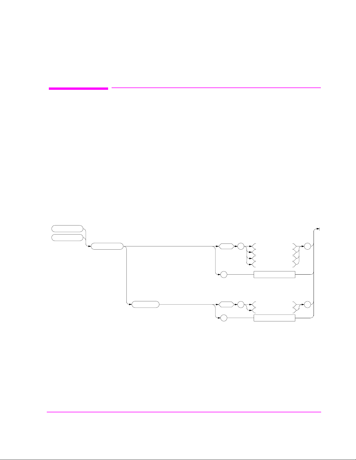
AF Generator 2 Pre-Modulation Filters
To improve performance, one of four pre-m odulation filters is automatic ally
selected for each Encoder Mode. The automatically selected filter can only be
changed using HP-IB commands; however , we recommend you do not change
this setting. In order to change the automatically select ed filter, the Filter Mode
must be set to ON. Filter Mode ON allows independent selec tion of filters. The
Filter Mode ON command must be executed first to override default settings.
Filter Mode OFF is the power up default state. The following error will occur if
the user attempt s to sel ect an alte rnat e filte r without first settin g the Fi lter Mode to
ON:
Entry not accepted. Auto entries take precedence . The synta x to
change or query the premodulation filter is shown below.
AFG2:FILTER:MODE ’ON|OFF’(select one)
AFG2:FILTER:MODE?(query the current mode setting)
AFG2:FILTER ’NONE|20kHz LPF|250Hz LPF|150Hz LPF’(select one)
AFG2:FILTER?(query the current filt er s etting)
AF Generator 2 Pre-Modulation Filters
:AFGenerator2
:ENCoder
:FILTER
:MODE
space
?
space
?
’
Returns quoted string
’
Returns quoted string
NONE
20kHz LPF
250Hz LPF
150Hz LPF
ON
OFF
’
’
95

AF Generator 2/Encoder
AF Gen erato r 2 /Encoder
:AFGenerator 2
:ENCoder
:AM
:BURSt
*:INCRement command only
:DESTination
(AFGen2 To)
:FM
See Real Number Setting Syntax
See IntegerNu mber Setting Syntax*
See Real Number Setting Syntax
space
?
’
Returns quoted stri ng
AM
FM
Audio Out
’
:FREQuency
:MODE
:OUTPut
:PEMPhasis
:POLarity
:SEND
See Real Number Setting Syntax*
*Does not include the :STATe command
See Real Number Setting Syntax
:MODE
space
?
space
?
space
?
space
’
NAMP-NTACS
Returns quoted string
’
Returns quoted string
’
Returns quoted string
’
Func Gen
Tone Seq
DTMF
CDCSS
Digi Page
AMPS-TACS
NMT
MPT 1327
LTR
EDACS
On
Off
Norm
Invert
Single
Burst
Cont
Step
’
’
’
’
?
:STOP
:AFG2 continued
96
Returns quoted string

:AMPS or :TACS
:AFGene rator2
:ENCoder
:AMPS
:TACS
:BUSY
(Busy/Idle)
:CHANnel
:DATA
:DELay
(B/I Delay)
:AM
:FM
:LEVel
space
?
See IntegerNu mber Setting Syntax*
*:INCRement command only
space
1
1
1
See Real Number Setting Syntax
?
See Real Number Setting Syntax
See Real Number Setting Syntax
’
Returns quoted stri ng
’
Returns quoted string
AF Generator 2/Encoder
Ilde
Busy
WS Delay
1stBitDly
On
Off
’
’
:RATE
:FILLer
:DATA 1
:DATA 2
:SEND
:STOP
:AFG2:AMP Continued On Next Page
:AFG2 continued
See Real Number Setting Syntax*
*Does not include the :STATe c ommand
space
?
’
Returns quoted st ring
1 AM, FM, and LEVel correspond to the setting of the AFGen2 To field.
string
’
97

AF Generator 2/Encoder
:AFGene rator2
:ENCoder
:AMPS
:TACS
:FVCMessage
space
’
string
’
:MESSage
:SAT
:STANDard
:AFG2 continued
:DATA 1
:DATA 2
:AM
:FM
:LEVel
:FREQuency
1
See Real Number Setting Syntax
1
See Real Number Setting Syntax
1
See Real Number Setting Syntax
See Real Numb er Setting Syntax*
*Does not include the :STATe command
?
space
?
space
?
’
’
1 AM, FM, and LEVel correspond to the se tting of the AFGen2 To field.
Returns quoted st ring
string
Returns quoted string
AMPS
TACS
JTACS
Returns quoted string
’
’
98

:NAMPs or :NTACs
:AFGenerator2
:ENCoder
AF Generator 2/Encoder
:NAMPs
:NTACs
:BUSY
:CHANnel
:FOCC
(Data Level &
Data Rate)
:DELay
:AM
:FM
:LEVel
:RATE
:FILLer
:MESSage
space
See IntegerNumber Setting Syntax*
*:INCRement command only
space
See Real Number Setting Syntax
See Real Number Setting Syntax
See Real Number Se t ting Syntax
See Real Number Setting Syntax*
*Does not include the :STATe c omman d
:DATA 1
:DATA 2
:SEND
:STOP
’
?
’
?
Ilde
Busy
WS Delay
1stBitDly
Returns quoted stri ng
Cntl
Voice
Returns quoted string
space
?
’
Returns quoted st ring
string
’
’
’
:AFG2 continued
:DATA 1
:DATA 2
:STANDard
:AFG2:NAMP Continued On Next Page
space
?
space
?
’
Returns quoted string
string
’
Returns quoted string
NAMPS
NTACS
’
’
99

AF Generator 2/Encoder
:AFGenerator2
:ENCoder
:NAMPs
:NTACs
:DSAT
:SEND
:STOP
:AFG2 continued
:FVC
:MESSage
:AM
:FM
:LEVel
:RATE
:MESSage
:SEND
space
?
See Real Number Setting Syntax
See Real Number Setting Syntax
See Real Number Setting Syntax
See Real Number Setting Syntax*
*Does not include the :STATe command
space
?
space
’
?
’
Returns quoted string
’
Returns quoted string
Message
DST
Returns quoted string
string
string
’
’
’
100
 Loading...