


Test Features
• Call processing and on-call
parametric test interface.
• High-level GPIB commands
simplify call processing
programmability.
• DCCH (TIA/EIA-136) phone test
with 83206A TDMA Cellular
Adapter for 800 and 1900 MHz bands.
• Accurate digital power measurements, with true-average TDMA
power measurements.
• VEE support with 8920B drivers.
• PCS (1710 to 1990 MHz) phone test
upgrade path with the 83236B PCS
interface.
Improve throughput and quality
The 8920B is a full-function RF test set with accuracy,
speed, and flexibility for testing land mobile radios, cellular telephones, and other communications systems
while improving throughput and quality in manufacturing.
Agilent 8920B
RF Communications Test Set
Technical Specifications
8920B with 83206A TDMA Cellular Adapter
83236B PCS Interface

2
83206A* (800 to 900 MHz)
* Supercedes the 83201B TDMA cellular adapter for DAMPS
(IS-54) test, adding DCCH (TIA/EIA-136) measurement capability.
8920B (30 MHz to 1GHz)
83236B (1710 to 1990 MHz)
TDMA Cellular Adapter for DAMPS (IS-54)
and DCCH (TIA/EIA-136) Test
• p/4 DQPSK signal generator
• p/4 DQPSK modulation analyzer
• Data source
• BER analyzer
RF Communications Test Set
• RF/AF signal generators
• AM/FM modulation analyzer
• RF/AF power meter
• Spectrum analyzer
• Tracking generator
• Adjacent channel power meter
• Oscilloscope
• IBASIC controller
• Signaling encoder/decoder
• Function generator
• AC/DC voltmeter
• SINAD/SNR meters
• DC current meter
• High stability reference
• IEEE 488.2/RS-232 interface
• Centronics port
PCS Interface
• Frequency translator for PCS-band measurements
• For more information on the 83236B, refer to literature
number 5964-9655E.
• Accuracy as good as stand
alone instruments
• Test speed lowers your cost
per test
• Flexibility meets more of your
testing needs
• Front-panel upgrades and builtin test simplifies upgrades and
maintenance

3
8920B Specifications
Specifications describe the instrument’s warranted
performance and are valid over the entire operating/
environmental range unless otherwise noted.
Supplemental Characteristics are intended to provide
additional information useful in applying the instrument by giving typical, but non-warranted, performance parameters. These characteristics are shown in
italics or labeled as “typical,” “usable to,” or “nominal.”
Note: The 8920B standard configuration and Options
006, 007, and 016 configurations can be ordered as a
variable attenuator and a fixed attenuator. For fixed
attenuators, see table below. For wider frequency and
power ranges, Option 055 has a mechanical variable
attenuator available.
Configuration Fixed Attenuator
Standard 14 dB
Option 006 6 dB
Option 007 0 dB
Option 016 16 dB
Signal Generator Specifications
RF Frequency
Range:
Standard and Options 006, 007, and 016: 30 MHz to 1 GHz
Option 055: (mechanical atten.) 250 kHz to 1 GHz
Accuracy and Stability: Same as reference oscillator ±0.015 Hz
Reference Oscillator Specifications
TCXO (8920B Standard)
Temperature: ±1 ppm (0 to +55 °C)
Aging: <2 ppm/year
Warm-Up Time: <30s to be within ±2 ppm of final
frequency. For higher stability reference, see Opt. 001.
Supplemental Characteristics
Switching Speed: <150 ms to be within 100 Hz of carrier frequency
Rear Panel BNC connectors:
Input Frequency: 1, 2, 5, and 10 MHz
Input Level: >0.15 Vrms
Output Frequency: 10 MHz
Output Level: >0.5 Vrms
Resolution: 1 Hz displayed
Output
RF IN/OUT Connector:
Level Accuracy: ±1.2 dB (level ≥–127 dBm)
If RF analyzer is also connected add ±0.1 dB
Typically ±1.0 dB for all levels.
Standard:
Level Range: –137 to –20.5 dBm into 50 W
Reverse Power: 60 watts continuous,
100 watts for 10 seconds per minute.
W/Option 006 (cellular power option):
Level Range: –137 to –12.5 dBm into 50 W
Reverse Power: 5.0 watts continuous,
7.5 watts for 10 seconds per minute.
W/Option 007 (low power option):
Level Range: –137 to –6.5 dBm into 50 W
Reverse Power: 1.2 watts continuous,
2.0 watts for 10 seconds per minute.
W/Option 016 (high power option):
Level Range: –137 to –22.5 dBm into 50 W
Reverse Power: 100 watts continuous,
125 watts for 10 seconds per minute.
Option 055:
Level Range: –137 to –19 dBm into 50 W
Reverse Power: 60 watts continuous,
100 watts for 10 seconds per minute.
W/Option 006 (cellular power option):
Level Range: –137 to –12.5 dBm into 50 W
Reverse Power: 5.0 watts continuous,
7.5 watts for 10 seconds per minute.
W/Option 007 (low power option):
Level Range: –137 to –6.5 dBm into 50 W
Reverse Power: 1.2 watts continuous,
2.0 watts for 10 seconds per minute.
W/Option 016 (high power option):
Level Range: –137 to –22.5 dBm into 50 W
Reverse Power: 100 watts continuous,
125 watts for 10 seconds per minute.
DUPLEX OUT Connector:
Level Accuracy: ±1 dB
Level Range:
Standard and Options 006, 007, 016: –127 to +3.5 dBm
into 50 W
Option 055: –127 to +7 dBm into 50 W
Reverse Power: 200 mW max.
SWR:
RF IN/OUT: <1.5:1
DUPLEX OUT: <2.0:1 (level <–4 dBm)
Supplemental Characteristics
Resolution: 0.1 dB

4
Spectral Purity
Spurious Signals:
Output port signal amplitude conditions
Fixed Attenuator to meet spurious specifications: output
Configuration signal must be ≤ to below value
Elect. Variable Duplex Port RF IN/OUT Port
Standard 1 dBm –27 dBm
Option 006 –2.5 dBm –20.5 dBm
Option 007 –2.5 dBm –14.5 dBm
Option 016 1 dBm –29 dBm
Mech. Variable Duplex Port RF IN/OUT Port
Option 055 1 dBm –25 dBm
Option 055 w/016 1 dBm –27 dBm
Harmonics: <–30 dBc
Non-Harmonic Spurious: <–60 dBc (at >5 kHz from carrier)
Residual FM (rms, CCITT):
250 kHz ≤ f
c
<249 MHz <7 Hz
249 MHz ≤ f
c
<501 MHz <4 Hz
501 MHz ≤ f
c
≤1000 MH <7 Hz
Supplemental Characteristics
Residual AM: <0.1% in a 50 Hz to 15 kHz BW
SSB Phase Noise (for >20 kHz offsets at 1 GHz): <–116 dB/Hz
FM
FM Deviation Maximum (for rates >25 Hz):
Standard and all Options:
100 kHz: for 501 MHz ≤f
c
<1000 MHz
50 kHz: for 249 MHz ≤f
c
<501 MHz
Standard and Options 006, 007, 016:
100 kHz: for 30 MHz ≤f
c
<249 MHz
Option 055 (mechanical variable attenuator):
100 kHz: for 250 kMHz ≤f
c
<249 MHz
(FM not specified for [f
c
minus FM dev.] <250 kHz)
FM Rate (1 kHz reference):
Internal: DC to 25 kHz (1 dB BW)
External:
AC Coupled: 20 Hz to 75 kHz
DC Coupled: DC to 75 kHz
FM Accuracy (1 kHz rate):
≤10 kHz dev: ±3.5% of setting ±50 Hz
>10 kHz dev: ±3.5% of setting ±500 Hz
FM Distortion (THD + Noise, in a 0.3 to 3 kHz BW):
<0.5% at >4 kHz deviation and 1 kHz rate
Center Frequency Accuracy in DC FM Mode:
(External source impedance <1 kW): ±500 Hz (after DC FM zero),
typically ±50 Hz.
Supplemental Characteristics
Ext. Mod. Input Impedance: 600 W nominal
Resolution: 50 Hz for <10 kHz deviation
500 Hz for ≥10 kHz deviation
AM
Standard:
Frequency Range: 30 MHz to 1000 MHz
AM Depth: 0 to 90% (usable to 99%) for DUPLEX OUT level
≤–2.5 dBm, for RF IN/OUT level depending on option.
Standard: ≤–26.5 dBm
Option 006: ≤–18.5 dBm
Option 007: ≤–12.5 dBm
Option 016: ≤–28.5 dBm
0 to 70% (usable 90%) with 8920B Option 051 rear panel
connectors for TDMA testing.
Options 055 (mechanical variable attenuator):
Frequency Range: 1.5 MHz to 1000 MHz
AM Depth: 0 to 90% (usable to 99%)
for DUPLEX OUT level ≤1 dBm
for RF IN/OUT level depending on option:
Standard: ≤–2.5 dBm
Option 016: ≤–27 dBm
AM Depth: 0 to 70% (usable to 90%) with 8920B Option 051
rear panel connectors for TDMA testing.
AM Rate: 20 Hz to 25 kHz (3 dB BW)
AM Accuracy (1 kHz rate):
≤10% AM: ±5% of setting, ±1.0% AM
>10% AM: ±5% of setting, ±1.5% AM
AM Distortion (THD+Noise 0.3 to 3 kHz BW):
<2% at 1 kHz rate, <30% AM
<3% at 1 kHz rate, ≤90% AM
Supplemental Characteristics
Ext. Mod. Input Impedance: 600 W nominal
Resolution: <0.1%
TDMA Signal Generator Specifications
8920B Opt. 001, 004, 051, 800 (8920B + 83206A)
Frequency Range: 824 MHz to 894 MHz
Output Level Range:
Standard:
DUPLEX OUT: +0.5 dBm to –127 dBm
RF IN/OUT range by option:
Standard: –23.5 dBm to –127 dBm
Option 006: –15.5 dBm to –127 dBm
Option 007: –9.5 dBm to –127 dBm
Option 016: –25.5 dBm to –127 dBm

5
Option 055 (mechanical variable attenuator):
DUPLEX OUT: +4.0 dBm to –127 dBm
RF IN/OUT range by option:
Standard: –22 dBm to –127 dBm
Option 016: –24 dBm to –127 dBm
Residual Error Vector Magnitude: <3.0%
Residual Phase Error: <2.0%
Residual Magnitude Error: <2.6%
IQ Origin Offset: <–30 dBc within 15 °C drift of last calibration
Frequency Error: ±4 Hz plus reference error
Audio Source Specifications
(Applicable to both internal sources)
Frequency
Range: dc to 25 kHz
Accuracy: 0.025% of setting
Supplemental Characteristics
Resolution: 0.1 Hz
Output Level
Range: 0.1 mVrms to 4 Vrms
Maximum Output Current: 20 mA peak
Output Impedance: <1 Ω (≤1 kHz rate)
Accuracy: ±2% of setting plus resolution
Residual Distortion: 0.125%
(THD plus noise, for amplitudes >200 mVrms), for tones
20 Hz to 25 kHz measured in an 80 kHz BW.
Supplemental Characteristics
Resolution: Level ≤0.01 V: ±50 µV
Level ≤0.1 V: ±0.5 mV
Level ≤1 V: ±5 mV
Level >1 V: ±50 mV
Offset in DC Coupled Mode: <50 mV
RF Analyzer Specifications
RF Frequency Measurements
Measurement Range:
Standard: 10 MHz to 1 GHz
Option 055 (mechanical variable attenuator):
400 kHz to 1 GHz
Level Range (with or without Option 055 mechanical variable
attenuator):
Standard: 0 to 48 dBm (1 mW to 60 W continuous)
50 dBm (100 W for 10 seconds per minute)
Option 006: –13 to 40 dBm (50 µW to 10 W continuous)
42 dBm (to 7.5 W for 10 seconds per minute)
Option 007: –14 to 34 dBm (40 µW to 2.4 W continuous)
36 dBm (2 W for 10 seconds per minute)
Option 016: 2 dBm to 50 dBm (1.6 mW to 100 W continuous)
51 dBm or (125 W for 10 seconds per minute)
Ant In: –36 dBm to +20 dBm in auto-tune mode
Accuracy: ±1 Hz plus timebase accuracy
Supplemental Characteristics
Frequency Resolution: 1 Hz
RF Power Measurements
Frequency Range:
Standard: 10 MHz to 1 GHz
Option 055 (mechanical variable attenuator): 400 kHz to 1 GHz
SWR: RF IN/OUT port <1.5:1
RF IN/OUT Measurement Range:
To achieve the specified accuracy when measuring power at the
RF In/Out port, the internal signal generator level must be 60 dB
below the measured power or less than –20 dBm at the Duplex
outport.
Standard: 1 mW to 60 W continuous (0 to 48 dBm)
or to 100 W for 10 seconds per minute (to 50 dBm)
Accuracy: ±5% of reading ±0.01 mW ±1 count for temperature
range of 25 ±10 °C.
Accuracy: ±10% of reading for operating temperature range.
Option 006: 50 µW to 10 W continuous (–13 to 40 dBm),
15 W for 10 seconds per minute (to 42 dBm)
Frequency Range: 30 MHz to 1 GHz
Accuracy: ±5% of reading ±0.5 µW ±1 count for tempera-
ture range of 25 ±10 °C.
Accuracy: ±10% of reading for operating temperature range.
Option 007 (low power option): 40 µW to 2.4 W continuous
(–14 to 34 dBm) to 4 W for 10 seconds per minute (36 dBm)
Accuracy: ±5% of reading ±400 nW ±1 count for temperature range of 25 ±10 °C.
Accuracy: ±10% of reading for operating temperature range.
Option 016 (high power option): 1.6 mW to 100 W continuous
(2 to 50 dBm), 125 W for 10 seconds per minute (to 51 dBm)
Accuracy: ±5% of reading ±0.01 mW ±1 count for temperature range of 25 ±10 °C.
Typical accuracy: ±6% of reading for operating temperature
range.
Supplemental Characteristics
Resolution: P >10W: 10 mW, P <10W: 10 mW,
P <100 mW: 0.1 mW, P <10 mW: 0.01 mW,
P <100 W: 100 mW, P >100 W: 1 W

6
FM Measurement
Frequency Range:
Standard, Options 006, 007, and 016: 30 MHz to 1 GHz
(usable to 400 kHz)
Option 055: 10 MHz to 1 GHz
(usable to 5 MHz)
Deviation: 20 Hz to 75 kHz
Sensitivity: 2 µV, typically <1 µV (15 kHz IF BW, high sensitivity
mode, 0.3 to 3 kHz BW, 12 dB SINAD for f
c
>10 MHz)
Accuracy: ±4% of reading plus residual FM and noise contribution
(20 Hz to 25 kHz rates, deviation ≤25 kHz).
Bandwidth (3 dB): 2 Hz to 70 kHz (DC FM measurements also
available)
THD+Noise: <1% distortion rms (for deviation ≥5 kHz and at a
rate of 1 kHz in a 0.3 to 3 kHz BW)
Input Level Range for Specified Accuracy:
ANT IN: –50 to +14 dBm (0.01 µW to 24 mW)
RF IN/OUT:
Standard: –14 to 48 dBm (40 µW to 60 W)
Option 006: –22 to 40 dBm (6.3 µW to 10 W)
Option 007: –28 to 34 dBm (1.6 µW to 2.4 W)
Option 016: –12 to 50 dBm (6.3 µW to 100 W)
Residual FM and Noise: <7 Hz (0.3 to 3 kHz, rms)
Supplemental Characteristics
Resolution: 1 Hz, f <10 kHz; 10 Hz, f ≥10 kHz
AM Measurement
Frequency Range:
Standard, Option 016: 10 MHz to 1 GHz (usable to 400 kHz)
Options 006, 007: 30 MHz to 1 GHz
Depth: 0 to 95%
Accuracy: ±5% of reading ±1.5% AM (50 Hz to 10 kHz rates,
modulation ≤80%)
THD+Noise: <2% rms for modulation ≤80% AM (at 1 kHz rate
in a 0.3 to 3 kHz BW)
Input Level for Specified Accuracy (levels in PEP):
Antenna: ANT IN:
–50 to +14 dBm (0.01 µW to +14 dBm)
RF IN/OUT:
Standard: –14 to 48 dBm (40 µW to 60 W)
Option 006: –22 to 40 dBm (6.3 µW to 10 W)
Option 007: –28 to 34 dBm (1.6 µW to 2.4 W)
Option 016: –12 to 50 dBm (63 µW to 100 W)
Residual AM: <0.2% in a 0.3 to 3 kHz BW
Supplemental Characteristics
Resolution: 0.05% AM for 0 to 10% AM
0.5% AM for 10 to 100% AM
SSB Measurement
Standard Frequency Range: 300 MHz to 1 GHz
Bandwidth (3 dB): 20 Hz to 70 kHz supplemental characteristics
Distortion and Noise: <3% (at 1 kHz rate in a 0.3 to 3 kHz BW)
TDMA Analyzer Specifications
8920B Opt. 001, 004, 051, 800 ( 8920B + 83206A)
Frequency Range: 824 MHz to 894 MHz
Input Level Range:
RF IN/OUT:
Standard: 1 mW to 60 W continuous (0 to 48 dBm),
100 W (to 50 dBm) for 10 seconds per minute
Option 006: 50 µW to 10 W continuous (–13 to 40 dBm),
15 W (42 dBm) for 10 seconds per minute
Option 007: 40 µW to 2.4 W continuous (–14 to +34 dBm),
4 W (36 dBm) for 10 seconds per minute
Option 016: 1.6 mW to 100 W continuous (2 to 50 dBm),
125 W (+51 dBm) for 10 seconds per minute
Input Frequency Setting Error: ±1 kHz
RX DSP Level Setting Range: –23 to 0 dB full scale
Residual Error Vector Magnitude: <1.3%
Error Vector Magnitude Measurement Accuracy: ±0.4% plus 2%
of reading
Residual Phase Error: <1.0°
Residual Magnitude Error: <0.9%
I/Q Origin Offset Accuracy: ±0.5 dB for values to –40 dBc
Frequency Error Accuracy: ±2.5 Hz plus reference accuracy
AF Analyzer Specifications
Frequency Measurement
Measurement Range: 20 Hz to 400 kHz
Accuracy: ±0.02% plus resolution plus reference accuracy
External Input: 20 mV to 30 Vrms
Supplemental Characteristics
Resolution: 0.01 Hz, f <10 kHz; 0.1 Hz, f <100 kHz; and 1 Hz for
f ≥100 kHz
AC Voltage Measurement
Measurement Range: 0 to 30 Vrms
Accuracy: ±3% rms of reading (20 Hz to 15 kHz, inputs ≥1 mV rms)

7
Residual Noise: 150 µV (15 kHz BW), <136 µV typical
Supplemental Characteristics
3 dB Bandwidth: Typically 2 Hz to 100 kHz
Nominal Input Impedance: Switchable between 1 MΩ in parallel
with 95 pF or 600 Ω floating
Resolution: For inputs ≥100 mV; 0.1 mV for inputs <100 mV; 0.01 mV
DC Voltage Measurement
Voltage Range: 100 mV to 42 V
Accuracy: ±1.0% of reading plus ±45 mV
Supplemental Characteristics
Resolution: 1 mV
Distortion Measurement
Tone Frequency Range: 300 Hz to 10 kHz
Tone Accuracy: ±5%
Input Level Range: 30 mV to 30 Vrms
Display Range: 0.1% to 100%
Accuracy: ±1 dB (0.5 to 100% distortion) for tones from 300 to
1500 Hz measured with the 15 kHz LPF.
±1.5 dB (1.5 to 100% distortion) for tones from 300 Hz to 10 kHz
measured with >99 kHz LPF.
Residual THD+Noise: –60 dBc or 150 µV, whichever is greater, for
tones from 300 to 1500 Hz measured with the 15 kHz LPF.
–52 dBc or 450 µV, whichever is greater, for tones from 300 Hz to
10 kHz measured with >99 kHz LPF.
Supplemental Characteristics
Resolution: 0.1% Distortion
SINAD Measurement
Tone Frequency Range: 300 Hz to 10 kHz
Tone Accuracy: ±5%
Input Level Range: 30 mV to 30 Vrms
Display Range: 0 to 60 dB
Accuracy: ±1 dB (0 to 46 dB SINAD) for tones from 300 to 1500 Hz
measured with the 15 kHz LPF.
±1.5 dB (0 to 36 dB SINAD) for tones from 300 Hz to 10 kHz measured with >99 kHz LPF.
Residual THD+Noise: –60 dBc or 150µV, whichever is greater, for
tones from 300 to 1500 Hz measured with the 15 kHz LPF.
–52 dBc or 450 µV, whichever is greater, for tones from 300 Hz to
10 kHz measured with >99 kHz LPF.
Supplemental Characteristics
Resolution: 0.01 dB
Audio Filters
Standard: <20 Hz HPF, 50 Hz HPF, 300 Hz HPF, 300 Hz LPF, 3 kHz
LPF, 15 kHz LPF, >99 kHz LPF, 750 µs de-emphasis
Optional: C-Message, CCITT, 400 Hz HPF, 4 kHz BPF, 6 kHz BPF
Variable Frequency Notch Filter
Frequency Range: 300 Hz to 10 kHz
Notch Depth: >60 dB
Notch Width: Typically ±5%
Audio Detectors
RMS, RMS*SQRT2, Pk+, Pk–, Pk+hold, Pk–hold,
Pk±/2, Pk±/2 hold, Pk±max, Pk±maxhold
Oscilloscope Specifications
Frequency Range: 2 Hz to 50 kHz (3 dB BW)
Amplitude Accuracy: ±1.5% of reading ±0.1 div. (20 Hz to 10 kHz)
Scale/Division: 10 mV to 10 V, settable 20 µV to 20 V
Time/Division: 10 µs to 100 ms, settable
Trigger Delay Range: 20 µs to 3.2 seconds
Supplemental Characteristics
3 dB Bandwidth: Typically >100 kHz
Internal DC Offset: ≤0.1 div. (≥50 µV/div. sensitivity)
Standard User Memory, RAM
Approximately 928 KB of RAM are available for nonvolatile
save/recall of settings. This typically will allow you to save
greater than 500 sets of instrument settings, depending on the
type of information saved.
Standard Rear Panel Interfaces
Current Sensing and I/O: GPIB/RS-232/Parallel (Centronics)
DC Current Meter
Measurement Range: 0 to 15 A (usable to 20 A)
Accuracy: The greater of ±10% of reading after zeroing or ±30 mA
(levels >100 mA)
Remote Programming
GPIB: A general purpose implementation of IEEE Standard 488.2

8
Functions Implemented: SH1, AH1, T6, L4, SR1, RL1, LE0, TE0,
PP0, DC1, DT1, C4, C11, E2
RS-232: Two serial ports through RJ-11 connector used for serial
data in and out.
Baud Rates: 150, 300, 600, 1200, 2400, 4800, 9600, and
19200 Hz
Memory Card Specifications
Card Compatibility: Single industry standard PCMCIA slot accepts
Type I or Type II SRAM and ROM memory cards.
Storage Capability: Allows for the storage and retrieval of IBASIC
program parameter and results data, input of new calibration data,
and long-term storage of Store/Recall information.
Firmware Upgrades: Accepts PCMCIA flash memory cards (4 MB)
to allow automatic loading of new firmware for the host CPU from
the front panel. Upgrade time is about two minutes.
8920B Options
Option 001, High Stability Timebase
OCXO: (Oven controlled crystal oscillator)
Temperature Drift: 0.05 ppm per year (0 to +55 °C)
Aging: 0.05 ppm per year (<1 ppm in first year)
Warm-up Time: <15 minutes to be within ±0.1 ppm of final frequency
Supplemental Characteristics
Rear Panel BNC connectors:
Input Frequency: 1, 2, 5, and 10 MHz
Input Level: >0.15 Vrms
Output Frequency: 10 MHz
Output Level: >0.5 Vrms
Option 004, Tone/Digital Signalling
Capability for generating and analyzing the formats listed here:
CDCSS, DTMF, 1-TONE, 2-TONE, 5/6 TONE SEQUENTIAL, RPC1,
(POCSAG), EIA, CCITT, CCIR, ZVEI, DZVEI, GOLAY, EEA, NMT-450,
NMT-900, LTR, AMPS/EAMPS/NAMPS, TACS/ETACS,
JTACS/NTACS, EDACS, MPT 1327, and TDMA dual-mode.
A general purpose function generator with: Sine, square, triangle,
ramp, dc, Gaussian white noise, uniform white noise.
Frequency range/level: Same as audio source
Option 006, 10 W to 50 µW Power
Measurement Range
Option 006 was designed to optimize the measurement range for
cellular mobile station test. This option has a 6 dB attenuator at
the RF IN/OUT port. It increases the dynamic range of the instrument by 2 dB and enables true-average power measurements on
TDMA signals using the 83206A (8920B Option 800). Option 006 is
recommended for TIA/EIA-136 testing. The RF frequency range for
Option 006 power measurement is 10 MHz to 1GHz, and the RF
source range is 30 MHz to 1 GHz RF.
Option 007, Low-level RF Power Measurements
Allows lower-level, higher sensitivity measurements. This option
reduces the maximum continuous input power of the 8920B from
60 watts to 2.4 watts. The RF frequency for Option 007 power
measurement is 10 MHz to 1 GHz and the RF source range is 30 MHz
to 1 GHz.
Option 010, 400 Hz High Pass Audio Filter
Option 011, CCITT Weighting Audio Filter
Option 012, 4 kHz Bandpass Audio Filter
Option 013, C-Message Weighted Audio Filter
Option 014, 6 kHz Bandpass Audio Filter
Option 016, High-Level RF Power Measurements to
100 W Continuous
Option 016 tests high power transmitters (up to 100 W continuous, 125 W intermittently with a 10 seconds per minute duty
cycle). It has a 16 dB fixed attenuator at the RF IN/OUT port.
Option 020, Radio Interface Card
The Option 020 for the 8920B is a built-in radio interface card for
automating module and radio test. It contains 16 parallel data
lines, two interrupts, and brings the audio in/out lines and a relay
closure out from the MIC/ACC connector on the front panel.
These are controlled by the 8920B IBASIC control language.

9
Option 051, Rear Panel Connectors for TDMA
Measurements for TDMA Option 800/801
This option provides the necessary rear panel connectors to work
with the 83206A TDMA cellular adapter (8920B Option 800/801).
Option 055, Mechanical Variable Input Attenuator
This option replaces the standard electronic input attenuator with
a mechanical version. Option 055 extends the RF source frequency
range to 250 kHz to 1 GHz, and the RF analyzer measurement
range to 400 kHz to 1 GHz. This option can be ordered with all
options except Options 006 and 007.
Option 102, Spectrum Analyzer with Tracking
Generator and ACP
Frequency Range:
Standard: 10 MHz to 1 GHz
Option 055 (mechanical variable attenuator): 400 kHz to 1 GHz
Frequency Span/Resolution Bandwidth (coupled):
Span Bandwidth
<50 kHz 300 Hz
<200 kHz 1 kHz
<1.5 MHz 3 kHz
<18 MHz 30 kHz
≥18 MHz 300 kHz, plus full span capability
Display: Log with 1, 2, and 10 dB/div.
Display Range: 80 dB
Reference Level Range: +50 to –50 dBm
Residual Responses: <–70 dBm (no input signal, 0 dB attenuation
for reference level ≤–20 dBm)
Image Rejection: >50 dBm for reference level ≤30 dBm
Non-harmonic Spurious Responses: >60 dBc (for input signals
≤–30 dBm at ANT IN port)
Supplemental Characteristics
Level Accuracy: ±2.5 dB
ANT IN Displayed Average Noise Level:
<–114 dBm for <50 kHz spans at reference level of –50 dBm
Log Scale Linearity: ±2 dB (for input levels ≤–50 dBm and/or
60 dB range)
Tracking Generator (In Option 102)
Frequency Range:
Standard and Options 006, 007, and 016: 10 MHz to 1 GHz
Option 055 (mechanical variable attenuator): 400 kHz to 1 GHz
Frequency Offset: Frequency span endpoints ± frequency offset
cannot be <400 kHz or ≥1 GHz
Output Level Range: Same as signal generator
Sweep Modes: Normal and inverted
Adjacent Channel Power (in Option 102)
Relative Measurements:
Level Range:
Antenna In: –40 dBm to +20 dBm
RF IN/OUT:
Standard: 1 mW to 60 W continuous or to 100 W for
10 seconds per minute
Option 006 (cellular power option): 50 µW to 10 W continuous, 7.5 W for 10 seconds per minute
Option 007 (low power option): 40 µW to 2.4 W continuous,
2.0 W for 10 seconds per minute
Option 016 (high power option): 1.6 mW to 100 W
continuous, 125 W for 10 seconds per minute
Option 055:
Level Range: –137 to –19 dBm into 50 W
Reverse Power: 60 watts continuous, 100 watts for
10 seconds per minute.
W/Option 006 (cellular power option):
Level Range: –137 to –12.5 dBm into 50 W
Reverse Power: 5.0 watts continuous, 7.5 watts for
10 seconds per minute.
W/Option 007 (low power option):
Level Range: –137 to –6.5 dBm into 50 W
Reverse Power: 1.2 watts continuous, 2.0 watts for
10 seconds per minute.
W/Option 016 (high power option):
Level Range: –137 to –21 dBm into 50 W
Reverse Power: 100 watts continuous,
125 watts for 10 seconds per minute.
Dynamic Range: Typical values for channel offsets
Channel offset Channel BW Dynamic range
12.5 kHz 8.5 kHz –65 dBc
20 kHz 14 kHz –68 dBc
25 kHz 16 kHz –68 dBc
30 kHz 16 kHz –68 dBc
60 kHz 30 kHz –65 dBc
Relative Accuracy: Typically ±2.0 dB

10
Absolute Level Measurements
Level: Results of absolute power in watts or dBm are calculated
by adding the ACP ratio from the spectrum analyzer to the carrier
power from the input section RF power detector.
Level Range:
Ant In: N/A
RF IN/OUT:
Standard: 1 mW to 60 W continuous
or to 100 W for 10 seconds per minute.
Option 006 (cellular power option): 50 µW to
10 W continuous, 15 W for 10 seconds per minute.
Option 007 (low power option): 40 µW to 2.4 W
continuous, 4.0 W for 10 seconds per minute.
Option 016 (high power option): 1.6 mW to 100 W
continuous, 125 W for 10 seconds per minute.
Option 055:
Level Range: –137 to –19 dBm into 50 W
Reverse Power: 60 watts continuous, 100 watts for
10 seconds per minute.
W/Option 006 (cellular power option):
Level Range: –137 to –12.5 dBm into 50 W
Reverse Power: 5.0 watts continuous, 7.5 watts for
10 seconds per minute.
W/Option 007 (low power option):
Level Range: –137 to –6.5 dBm into 50 W
Reverse Power: 1.2 watts continuous, 2.0 watts for
10 seconds per minute.
W/Option 016 (high power option):
Level Range: –137 to –21 dBm into 50 W
Reverse Power: 100 watts continuous,
125 watts for 10 seconds per minute.
Dynamic Range: Typical values for channel offsets
Channel Offset Channel BW Dynamic Range
12.5 kHz 8.5 kHz –65 dBc
20 kHz 14 kHz –68 dBc
25 kHz 16 kHz –68 dBc
30 kHz 16 kHz –68 dBc
60 kHz 30 kHz –65 dBc
Absolute Accuracy: Equals the sum of RF power measurement
accuracy found in the RF analyzer section and the ACP typical
relative accuracy of ±2.0 dB.
Option 800, Dual-mode TDMA Cellular Adapter –
TIA/EIA-136 DCCH, IS-54 DAMPS
The 8920B Option 800 includes the 83206A TDMA cellular adapter
attached, tested, and calibrated with the 8920B communications
test set.
Option 801, Dual-Mode Adapter and PCS Interface
For TIA/EIA 136 testing in 800 and 1900 MHz bands. This option
is for ordering convenience. It includes the 8920B with the
83206A attached and pretested together plus the additional unit
83236B PCS interface shipped together.
General Specifications
Dimensions
8920B: 7.5 in.H x 13 in.W x 19 in.D (188 x 330 x 456 mm)
8920B Option 800 (83206A attached): 9.8 in.H x 13 in.W x 19 in.D
(250 x 330 x 456 mm)
Weight (fully optioned)
8920B: 37 lb net (16.8 kg)
Shipping Weight: 61 lb net (27.7 kg)
8920B Option 800: ( 83206A attached) 50 lb net (22.7 kg)
Shipping Weight: 80 lb net (36.3 kg)
Power
8920B:
AC: 100 V to 240 V ±10%, 48 to 440 Hz, nominally 100 watts
DC: 11 V to 28 V, nominally 120 watts
8920B Option 800 (83206A attached):
AC: 100 V to 240 V ±10%, 48 to 440 Hz, nominally 140 watts
General
CRT Size: 7 x 10 cm
Operating Temperature: 0 to +55 °C
Storage Temperature: –55 to +75 °C
Calibration Interval: Two years
Supplemental Characteristics
Leakage: At signal generator output frequency and level <–40 dBm,
typical 8920B leakage is <1.0 µV (2.0 mV for 8920B Option 800)
induced in a resonant dipole antenna one inch from any surface
except the rear panel. Spurious leakage levels are typically <1 µV
in a resonant dipole antenna.

11
8920B front and rear panels
12
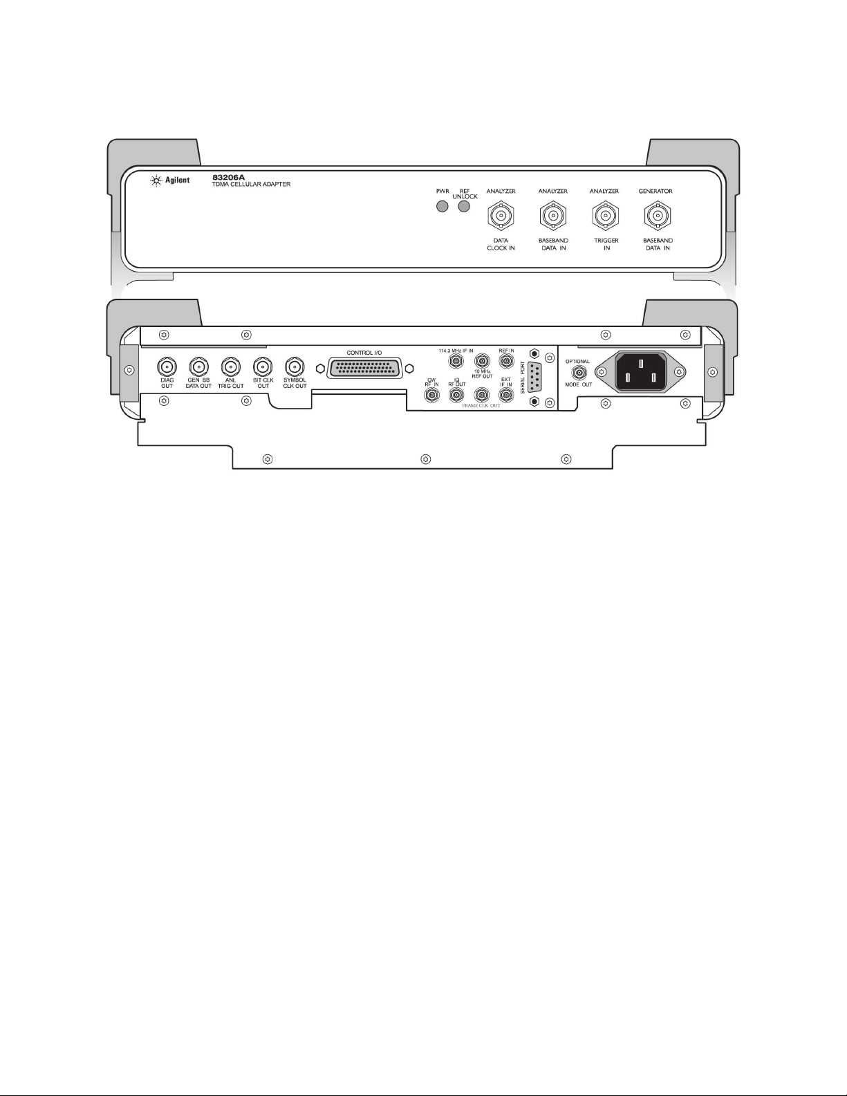
83206A front and rear panels

13
83236B front and rear panels

Agilent Technologies’ Test and Measurement
Support, Services, and Assistance
Agilent Technologies aims to maximize
the value you receive, while minimizing
your risk and problems. We strive to
ensure that you get the test and measurement capabilities you paid for and obtain
the support you need. Our extensive support resources and services can help you
choose the right Agilent products for your
applications and apply them successfully.
Every instrument and system we sell has
a global warranty. Support is available
for at least five years beyond the production life of the product. Two concepts
underlie Agilent’s overall support policy:
“Our Promise” and “Your Advantage.”
Our Promise
“Our Promise” means your Agilent test
and measurement equipment will meet its
advertised performance and functionality.
When you are choosing new equipment,
we will help you with product information, including realistic performance specifications and practical recommendations
from experienced test engineers. When
you use Agilent equipment, we can verify
that it works properly, help with product
operation, and provide basic measurement
assistance for the use of specified capabilities, at no extra cost upon request. Many
self-help tools are available.
Your Advantage
“Your Advantage” means that Agilent
offers a wide range of additional expert
test and measurement services, which you
can purchase according to your unique
technical and business needs. Solve problems efficiently and gain a competitive edge
by contracting with us for calibration, extracost upgrades, out-of-warranty repairs, and
on-site education and training, as well
as design, system integration, project management, and other professional services.
Experienced Agilent engineers and technicians worldwide can help you maximize
your productivity, optimize the return on
investment of your Agilent instruments and
systems, and obtain dependable measurement accuracy for the life of those products.
By internet, phone, or fax, get assistance
with all your test and measurement needs.
Online Assistance
www.agilent.com/find/assist
Phone or Fax
United States:
(tel) 1 800 452 4844
Canada:
(tel) 1 877 894 4414
(fax) (905) 206 4120
Europe:
(tel) (31 20) 547 2323
(fax) (31 20) 547 2390
Japan:
(tel) (81) 426 56 7832
(fax) (81) 426 56 7840
Latin America:
(tel) (305) 269 7500
(fax) (305) 269 7599
Australia:
(tel) 1 800 629 485
(fax) (61 3) 9210 5947
New Zealand:
(tel) 0 800 738 378
(fax) (64 4) 495 8950
Asia Pacific:
(tel) (852) 3197 7777
(fax) (852) 2506 9284
Product specifications and descriptions in this
document subject to change without notice.
Copyright © 2000 Agilent Technologies
Printed in U.S.A. 11/00
5968-1376E
For more product information please visit:
www.agilent.com/find/8920support
 Loading...