

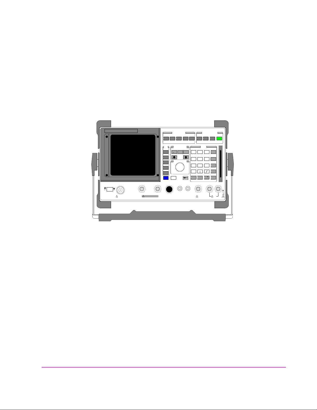
Agilent Technologies 8920A
RF Communications Test Set
User’s Guide
Firmware Version A.18.01 an d above
POWE
OF O
SCREEN CONTROL
CONFIHELPMSSG HOLD PRINT
DUPLETXRX PREV TESTS
DATA FUNCTIONS
USER
k1’
REF
METER
INCR
INCR
k1
k2’
LO HI
k2
k3’
CURSOR CON-
k3
ASSIG
k4
RELEA
PUSH TO
k5
SHIFT
CANCE
MIC/
!
MAX POWER
!
ANT INDUPLEX OUTRF IN/OUT
MAX POWER 200
Agilent Part Number: 08920-90219
Printed in U. S. A.
April 2000
Rev. C
AVG
INCR
ON/OFF
INSTRUMENT STATE
ADRS
SAVE
LOCAL
RECAL
DATA
789
456
123
_
+
0
NO
YES
AUDIO SQUELCVOL-
MAX
!
MEAS
ENTER
dB
GHz
%
MHz
s
kHz
Hzms% Ωppm
AUDIO IN
!
PRESE
MEMO
LOHI
MAX
1

© Copyright Agilent Technologies 1998-2000
Notice No part of this manual may be reproduc ed in any form or by any means (i ncluding
electronic sto rage and retrie val or translat ion into a for eign language) wit hout prior
agreement and written consent from Agilent Technologies Inc. as governed by
United States and international copyright laws.
The material contained in this document is subject to change without notice.
Agilent Technologies makes no warranty of any kind with regard to th is mate rial,
including, but not limit ed to, the implied war ranties of merc hantabil ity and fi tness
for a particular purpo se. Agilent Technologies Inc. shall not be liable fo r errors
contained herein or for inciden tal or conseque ntial damages in connection wi th the
furnishing, performance, or use of this material.
U.S. Government users will receive no greater than Limited Rights as defined in
FAR 52.227-14 (June 1987) or DFAR 252.227-7015 (b)(2) (November 1995), as
applicable in any technical data.
Agilent Technologies
Learning Products Department
24001 E. Mission
Liberty Lake, WA 99019-9599
U.S.A.
Edition/Print Date All Editions and Updates of this manual and their creation dates are listed below.
Rev. A . . . . . December 1997
Rev. B . . . . . March 1998
Rev. C . . . . . April 2000
2

Safety Summary The following gener al safety prec autions must be observed du ring all phase s of op-
eration of this instr ument. Failure to comply with thes e precautions or with specifi c
warnings elsewhere in this manual violates safety standards of design, manufacture, and intended use of the instrument. Agilent Technologies Inc. assumes no liability for the customer’s failure to comply with these requirements.
GENERAL
This product is a Safety Class 1 instrument (provided with a protective earth terminal). The protective features of this product may be impaired if it is used in a
manner not specified in the operation instructions.
All Light Emitting Diodes (L EDs) used in this product are Class 1 LEDs as per IEC
60825-1.
This product has been designed and tested in accordance with IEC Publication
1010, "Safety Requirements for Electronic Measuring Apparatus," and has been
supplied in a safe condition. This ins tr uct io n d ocumentation contains information
and warnings which must be followed by the user to ensure safe operation and to
maintain the product in a safe condition.
ENVIRONMENTAL CONDITIONS
This instrument is intended for indoor use in an installation category II, pollution
degree 2 environment. It is desi gned to operate at a maximum relative humi dity of
95% and at altitudes of up t o 2000 meters. Re fer to the s pecifications tables for the
ac mains voltage requirements and ambient operating temperature range.
V entilation Requirements: When installing the product in a cabinet, the convection
into and out of the product must not be restricted. The ambient temperature (outside the cabinet) must be les s than the maximum operating temperature of the prod-
uct by 4° C for every 100 watts dissipated in the cabinet. If the total power
dissipated in th e cabi net is gr eater than 8 00 watts , t hen for ced con vec tion mus t be
used.
BEFORE APPLYING POWER
Verify that the product is set to match the available line voltage, the correct fuse is
installed, and all s afety precaut ions are ta ken. Note the inst rument's exter nal markings described under Safety Symbols.
3

GROUND THE INSTRUMENT
T o mi nimize s hock hazard , the inst rument chas sis and c over must be connec ted to
an electrical protective earth ground. The instrument must be connected to the ac
power mains through a grounded power cable, with the ground wire firmly connected to an elec trical ground (safety ground) at the power outlet. Any inte rruption
of the protective (grounding) conductor or disconnection of the protective earth
terminal will cause a potential shock hazard that could result in personal injury.
FUSES
Only fuses with the requ ired rated current, voltage, and spe cified type (normal
blow , time de lay, etc.) should be used. Do not use repai red fuses or short-cir cuited
fuse holders. To do so could cause a shock or fire hazard.
DO NOT OPERATE IN AN EXPLOSIVE ATMOSPHERE
Do not operate the instrument in the presence of flammable gases or fumes.
DO NOT REMOVE THE INSTRUMENT COVER
Operating personnel mus t not remove in strument cover s. Component repl acement
and internal adjustments must be made only by qualified service personnel.
Instruments that appear damaged or defective should be made inoperative and secured against un intended operation until they can be repaired by quali fied service
personnel.
WARNING: The WARNING sign denotes a hazard. It calls attention to a procedure, practice, or
the like, which, if not correctly performed or adhered to, could result in personal
injury. Do not proceed beyond a WARNING sign until the in dicated conditions are
fully understood and met.
CAUTION: The CAUTION sign denotes a hazard. It calls attention to an operating procedure, or the
like, which, if not correctly performed or adhered to, could result in damage to or
destruction of part or all of the product. Do not proceed beyond a CAUTION sign until the
indicated conditions are fully understood and met.
4
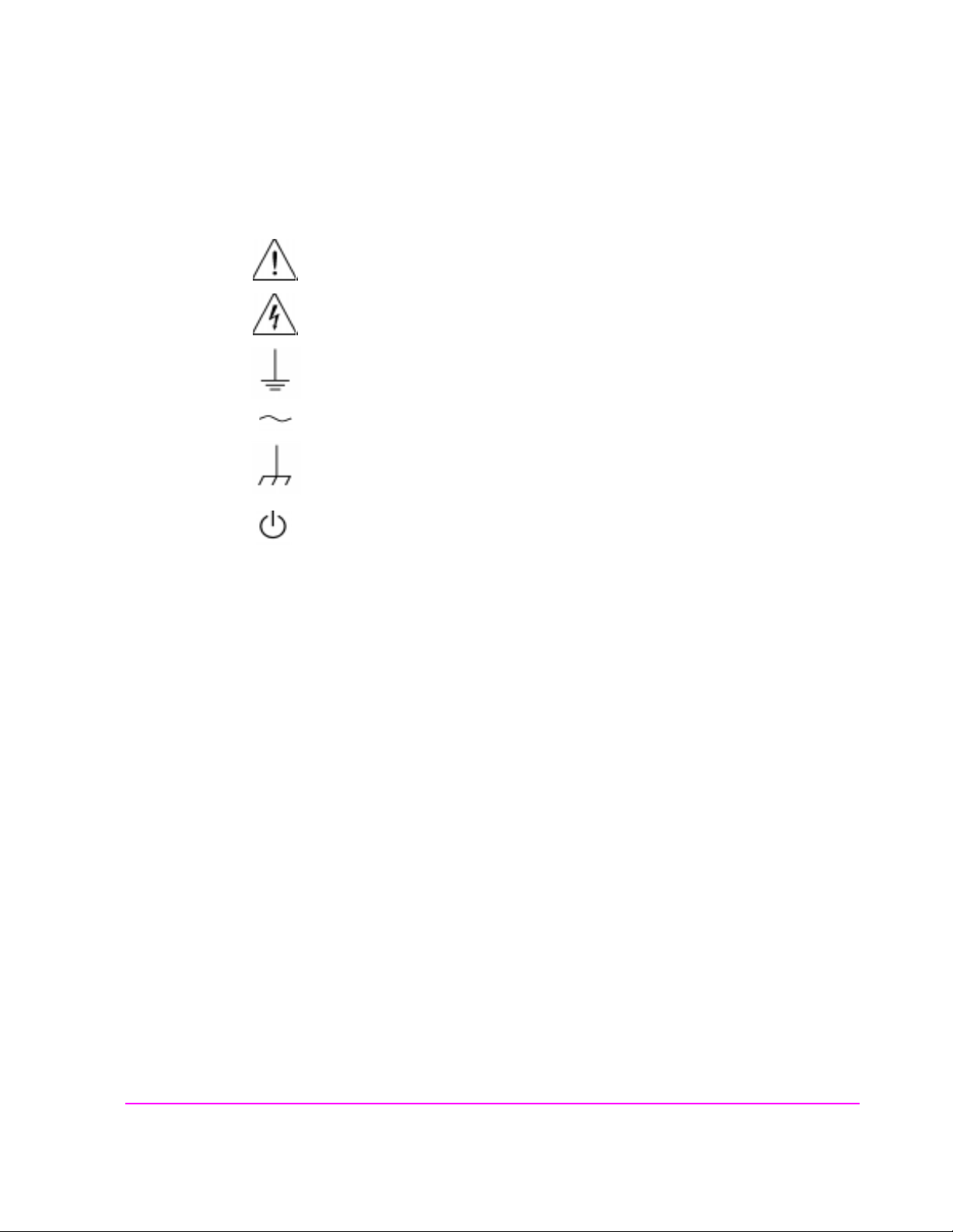
Safety Symbols
Caution, refer to accompanying documents
Warning, risk of electric shock
Earth (ground) terminal
Alternating current
Frame or chassis terminal
Standby (supply). Units with this s ymbol are not compl etely disco nnected from a c
mains when th is switch is off.
T o completely disconnec t the unit from ac mains, either disco nnect the power cord,
or have a qualified electrician install an external switch.
Product Markings CE - the CE mark is a registered trademark of the European Community. A CE
mark accompanied by a year indicated the year the design was proven.
CSA - the CSA mark is a registered trademark of the Canadian Standards Associ-
ation.
CERTIFICATION Agilent Technologies certifies that this product met its published specifications at
the time of shipment fr om the fac tory . Agilent T echnol ogies further cer tifies tha t its
calibration measurements are traceable to the United States National Institute of
Standards and Technology, to the extent allowed by the Institute’s calibration facility, and to the calibration facilities of other International Standards Organization members
5

Agilent Technologies Warranty Statement for Commercial Products
Agilent Technologies 8920A RF Communications Test Set
Duration of
Warranty: 1 year
1. Agilent Technologies warrants Agilent Technologies hardware, accessories and
supplies against defects in materials and workmanship for the period specified above.
If Agilent Technologies receives notice of such defects during the warranty period,
Agilent Technologies will, at its option, either repair or replace products which prove
to be defective. Replacement products may be either new or like-new.
2 Agilent Technologies warrants that Agilent Technologies software will not fail to exe-
cute its programming instructions, for the period specified above, due to defects in material and workmanship when properly installed and used. If Agilent Technologies
receives notice of such defects during the warranty period, Agilent Technologies will
replace software media which does not execute its programming instructions due to
such defects.
3. Agilent Technologies does not warrant that the operation of Agilent Technologies
products will be uninterrupted or error free. If Agilent Technologies is unable, within
a reasonable time, to repair or replace any product to a condition as warranted,
customer will be entitled to a refund of the purchase price upon prompt return of the
product.
4 Agilent Technologies products may contain remanuf actured parts equ ivalent to new in
performance or may have been subject to incidental use.
5. The warranty period begins on the date of delivery or on the date of installation if
installed by Agilent Technologies. If customer schedules or delays Agilent
Technologies installation more than 30 days after delivery, warranty begins on the 31st
day from delivery.
6 Warranty does not apply to defects resulting fro m (a) improper or inadequate mainte-
nance or calibration, (b) software, interfacing, parts or supplies not supplied by Agilent
Technologies, (c) unauthorized modification or misuse, (d) operation outside of the
published environmental specifications for the product, o r (e) improper site preparation
or maintenance.
7 TO THE EXTENT ALLOWED BY LOCAL LAW, THE ABOVE WARRANTIES
ARE EXCLUSIVE AND NO OTHER WARRANTYOR CONDITION, WHETHER
WRITTEN OR ORAL IS EXPRESSED OR IMPLIED AND AGILENT TECHNOLOGIES SPECIFICALLY DISCLAIMS ANY IMPLIED WARRANTIES OR CONDITIONS OR MERCHANTABILITY, SATISFACTORY QUALITY, AND FITNESS
FOR A PARTICULAR PURPOSE.
6

8. Agilent Technologies will be liable for damage to tangible property per incident up to
the greater of $300,000 or the actual amou nt pai d for the prod uct that i s the subject of
the claim, and for damages for bodily injury or death, to the extent that all such damages are determined by a court of competent jurisdiction to have been directly caused
by a defective Agilent Technologies product.
9. TO THE EXTENT ALLOWED BY LOCAL LAW, THE REMEDIES IN THIS
WARRANTY STATEMENT ARE CUSTOMER’S SOLE AND EXCLUSIVE
REMEDIES. EXCEPT AS INDICATED ABOVE, IN NO EVENT WI LL AGIL ENT
TECHNOLOGIES OR ITS SUPPLIERS BE LIABLE FOR LOSS OF DATA OR FOR
DIRECT, SPECIAL, INCIDENTAL, CONSEQUENTIAL (INCLUDING LOST
PROFIT OR DATA), OR OTHER DAMAGE, WHETHER BASED IN CONTRACT,
TORT, OR OTHERWISE.
FOR CONSUMER TRANSACTIONS IN AUSTRALIA AND NEW ZEALAND:
THE WARRANTY TERMS CONTAINED IN THIS STATEMENT, EXCEPT TO
THE EXTENT LAWFULLY PERMITTED, DO NOT EXCLUDE RESTRICT OR
MODIFY AND ARE IN ADDITION TO THE MANDATORY STATUTORY
RIGHTS APPLICABLE TO THE SALE OF THIS PRODUCT TO YOU.
ASSISTANCE Product maintenance agreements and other customer assistance agreements are
available for Agilent Technologies products. For any assistance, contact your
nearest Agilent Technologies Sales and Service Office.
7

DECLARATION OF CONFORMITY
according to ISO/IEC Guide 22 and EN 45014
Manufacturer’s Name:
Agilent Technologies
Manufacturer’s Address:
24001 E. Mission Avenue
Liberty Lake, Washington 99019-9599
USA
declares that the product
Product Name:
Model Number:
Product Options:
RF Communications T est Set / Cell Site Test Set
A g i l e nt Te c h n o l o gi e s 8 9 20 A , 8 92 0 B , a nd 8 92 1 A
This declaration covers all options of th e above
product.
conforms to the following Product specifications:
Safety: IEC 1010-1:1990+A1+A2/EN 61010-1:1993
EMC: CISPR 11:1990 / EN 55011:1991 Group 1, Class A
EN 50082 -1 : 1 9 9 2
IEC 801-2:1991 - 4 kV CD, 8 kV AD
IEC 801-3:1984 - 3V/m
IEC 801-4:1988 - 0.5 kV Sig. Lines, 1 kV Power Lines
Supplementary Information:
This is a class A product. In a domestic environment this product may cause radio interference in
which case the user may be required to take adequate measures.
This product herewith complies with the requirements of the Low Voltage Directive
73/23/EEC and the EMC Directive 89/336/EEC and carries the CD-marking accordingly
Spokane, Washington USA November 20, 1998 Vince Roland/Quality Manager
8
.

Table 1 Regional Sales Offices
United States of America:
Agilent Technologies
Test and Measurement Call Center
P.O. Box 4026
Englewood, CO 80155-4026
(tel) 1 800 452 4844
Japan:
Agilent Technologies Japan Ltd.
Measurement Assist ance Center
9-1 Takakura-Cho, Hachioji-Shi,
Tokyo 192-8510, Japan
(tel) (81) 456-56-7832
(fax) (81) 426-56-7840
Asia Pacific:
Agilent Technologies
24/F, Cityplaza One,
111 Kings Road,
Taikoo Shing, Hong Kong
Canada:
Agilent Technologies Canada Inc.
5150 Spectrum Way
Mississauga, Ontario
L4W 5G1
(tel) 1 877 894 4414
Latin America:
Agilent Technologies
Latin America Region
Headquarters
5200 Blue Lagoon Drive,
Suite #950
Miami, Florida 33126
U.S. A.
(tel) (305) 267 4245
(fax) (305) 267 4286
Europe:
Agilent Technologies
European Marketing Organization
P.O. Box 999
1180 AZ Amstelveen
The Netherlands
(tel) (3120) 547 9999
Australia/New Zealand:
Agilent Technologies
Australia Pty Ltd.
347 Burwood Highway
Forest Hill, Victoria 3131
Australia
(tel) 1 800 629 485
(fax) (61 3) 9272 0749
New Zealand
(tel) 0 800 738 378
(fax) (64 4) 802 6881
(tel) (852) 3197 7777
(fax) (852) 2506 9233
9

Service and
Support
Table 2
Any adjustment, maintenance, or repair of this p roduct must be performed by qu alified personnel. Contact your customer engineer through your local Agilent Technologies Service Cen ter. You can find a list of local service representat ive s on the
Web at:
http://www.agilent-tech.com/services/English/index.html
If you do not have ac cess to the I nternet, one of these centers c an direct you t o your
nearest representative:
United States Test and Measu rement Call Center
(Toll free in US)
Europe
Canada
Japan Measurement Assistance Center
Latin America
Australia/New Zealand
Asia-Pacific
(800) 452-4844
(31 20) 547 9 900
(905) 206-4725
(81) 426 56 7832
|(81) 426 56 7840 (FAX)
(305) 267 4288 (FAX)
1 800 629 485 (Australia)
0800 738 378 (New Zealand)
(852) 2599 7777
(852) 2506 9285 (FAX)
10

Manufacturer’s
Declaration
This statement is provi ded to co mply with the req uiremen ts of t he German Sou nd
Emission Directive, from 18 January 1991.
This product has a sound pressure emission (at the operator position) < 70 dB(A).
• Sound Pressure Lp < 70 dB(A).
• At Operator Position.
• Normal Operation.
• According to ISO 7779:1988/EN 27779:1991 (Type Test).
Herstellerbescheinigung
Diese Information steht im Zusammenhang mit den Anforderungen der
Maschinenlärminformationsverordnung vom 18 Januar 1991.
• Schalldruckpegel Lp < 70 dB(A).
• Am Arbeitsplatz.
• Normaler Betrieb.
• Nach ISO 7779:1988/EN 27779:1991 (Typprüfung).
11

In this Book The Agilent 8920A is refer red to in this document as the "Test Set."
Chapter 1, Get Started
This chapter describes the basic operation of the Test Set. It also provides a quick
check that verifies that the Test Set is operating properly.
Chapter 2, Configuring Your Test Set
This chapter describes various instrument configuration settings that affect the general
operation of the instrument.
Chapter 3, Operating Overview
This chapter contains detailed operating instructions a nd examp les for using several
instrument features.
Chapters 4 through 23, Screen and Field Descriptions
These chapters contains reference information for each screen an d its fields. Man y of
the descriptions contain signal flow diagrams that relate the screen’s fields to the functions they perform. The screens are arranged in alphabetical order by title at the top of
the screen; Signaling Encoder and Signaling Decoder are alphabetized by the names
Encoder and Decoder.
Chapter 24, Connector, Key, and Knob Descriptions
This chapter describes the purpose and use of each connector and control.
Chapter 25, Modifications, Accessories, Manuals, Support
This chapter describes retrofit kits, accessories, manuals, and customer support available for your Test Set.
Error Messages
This section discusses error and operating messages.
12

Contents
1 Get Started
Before Connecting a Radio 40
Accessing the Test Set’s Screens 41
Changing A Field’s Setting 43
How do I Verify that the Test Set is Operating Properly? 46
Instrument Functional Diagram 47
13

Contents
2 Configuring Your Test Set
General Operating Info rmation 50
14

Contents
Operating Overview
3
Interaction Between Screens 54
Displaying Measurements 57
Entering and Changing Numbers 63
Printing A Screen 66
Using Measurement Limit Indicators 67
Averaging Measurements 69
Setting A Measurement Reference 70
Using Memory Cards 71
Saving and Recalling Instrument Setups 76
Using USER Keys 80
Setting an RF Generator/Analyzer Offset 84
Using Remote Control 85
15

Contents
4 Adjacent Channel Power Screen
How the Test Set Measures Adjacent Channel Power (ACP) 90
Field Descriptions 91
16

Contents
5 AF Analyzer Screen
Block Diagram 100
17

Contents
6 Call Processing Subsystem
Description of the Call Processing Subsystem 114
Using the Call Processing Subsystem 118
The CALL CONTROL Screen 122
Using the CALL CONTROL Screen to Test Call Processing
Functions 134
CALL DATA Screen 144
CALL DATA Screen Message Field Descriptions 149
Using the CALL DATA Screen 158
CALL BIT Screen 166
CALL BIT Screen Message Field Descriptions 172
Using the CALL BIT Screen 192
ANALOG MEAS Screen 197
Using the ANALOG MEAS Screen 200
CALL CONFIGURE Screen 203
18

Contents
7 Configure Screen
Field Descriptions 206
19

Contents
8 Signaling Decoder Screen
Field Descriptions for Decoder Modes 220
AMPS-TACS, NAMPS-NTACS Decoder 221
Using the AMPS/TACS, NAMPS/NTACS Decoder 226
Continuous Digital Controlled Squelch System Decoder 230
Using the CDCSS Decoder 234
Digital Paging Decoder 235
Dual-Tone Multi-Frequency (DTMF) Decoder 239
Using the DTMF Decoder 244
EDACS Decoder 245
Using the EDACS Decoder 248
Function Generator Decoder 251
Using the Function Generator Decoder 254
LTR Decoder 255
Using the LTR Decoder 259
MPT 1327 Decod er 261
NMT Decoder 266
Using the NMT Decoder/Encoder 271
Creating NMT Tests 276
Tone Sequence Decoder 285
20

Contents
9 Duplex Test Screen
Block Diagram 290
Field Descriptions 291
21

Contents
Signaling Encoder (AF Generator 2)
10
Field Descriptions for Encoder Modes 304
AMPS-TACS NAMPS-NTACS Encoder 305
Using the AMPS-TACS, NAMPS-NTACS Encoder 318
CDCSS Encoder 319
Using the CDCSS Encoder 323
Digital Paging Encoder 324
DTMF Sequence Encoder 329
EDACS Encoder 333
Using the EDACS Encoder 339
Function Generator Encod er 344
LTR Encoder 347
Using the LTR Encoder 351
MPT 1327 Encod er 355
Using the MPT 1327 Encoder 368
Nordic Mobile Telephone (NMT) Encoder 371
Tone Sequence Encoder 383
22

Contents
11 Help Screen
Field Descriptions 388
23

Contents
12 I/O Configure Screen
Field Descriptions 390
24

Contents
13 Message Screen
Field Descriptions 396
25

Contents
14 Oscilloscope Screen
Field Descriptions 398
Using the Oscilloscope 404
26

Contents
15 Print Configure Screen
Field Descriptions 406
27

Contents
16 Radio Interface Screen
Radio Interface Functional Description 410
Field Descriptions 412
Using the Radio Interface (Manual Operation) 415
Using The Radio Interface (Remote Operation) 421
28

Contents
17 RF Analyzer Screen
Block Diagram 424
Field Descriptions 425
29

Contents
18 RF Generator Screen
Block Diagram 436
Field Descriptions 437
30

Contents
19 RX Test Screen
Block Diagram 446
Field Descriptions 447
31

Contents
20 Service Screen
Field Descriptions 454
32

Contents
21 Spectrum Analyzer Screen
Field Descriptions 458
Using the Spectrum Analyzer 470
33

Contents
22 Tests Screen
Description of the Tests Subsystem 472
TESTS (Main Menu) 474
TESTS (Channel Information) 477
TESTS (Test Parameters) 479
TESTS (Order of Tests) 480
TESTS (Pass/Fail Limits) 482
TESTS (Save/Delete Procedure) 484
TESTS (Execution Conditions) 487
TESTS (External Devices) 490
TESTS (Printer Setup) 493
TESTS (IBASIC Controller) 496
ROM Programs 498
34

Contents
23 TX Test Screen
Block Diagram 502
Field Descriptions 503
35

Contents
24 Connector, Key, and Knob Descriptions
Connector Descriptions 514
Key Descriptions 532
Knob Des criptions 536
36

Contents
25 Modifications, Accessories, Manuals Support
Modifications 538
Accessories 541
Agilent Technologies Support for Your Instrument 553
37

Contents
Index 569
38

1
Get Started
39
Chapter 1, Get Started
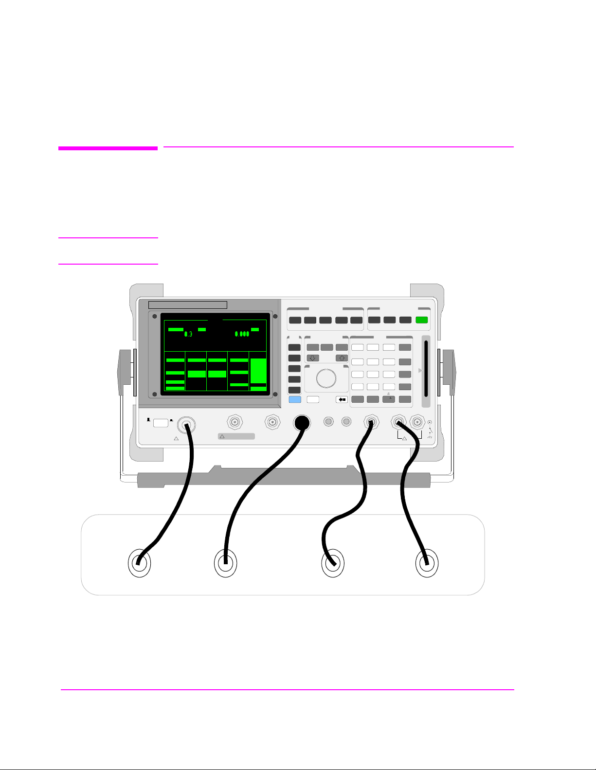
Before Connecting a Radio
Before Connecting a Radio
The RF IN/OUT port should be used for all transmitter tests when the radio is connected
directly to the Test Set. (All UUT transmitter power measurements are made through this
port). Off-the-air measurements can be made using the ANT IN port.
CAUTION: Overpower Damage — Refer to the Test Set’s front panel for maximum input power level.
Exceeding this level can cause permanent instrument damage.
POWER
0
OFF0ON
SINAD dB
RF Gen Freq
AFGen1 Freq
100.000000
AFGEN1 To
Amplitude
FM
-80.0
dBm
Atten Hold
On/Off
Output Port
RF Out/Dupl
RF IN/OUT
MAX PWR 60W
!
CONTINUOUS
RX TEST
AF Gen2 Freq
1.0000
1.0000
kHzMHz
AFGEN2 To
FM
Off
Off
kHz
DUPLEX OUT ANT IN
AC Level
Filter 1
50Hz HPF
kHz
Filter 2
15kHz LPF
Ext Load R
8.00
!
MAX POWER 200mW
V
To Screen
RF GEN
RF ANL
AF ANL
SCOPE
SPEC ANL
ENCODER
DECODER
RADIO INT
More
MSSG
RX
USER
k1
ENTER
k2’
k2
k3’
k3
ASSIGN
k4
RELEASE
k5
SHIFT CANCEL
SCREEN CONTROL
HELPTXCONFIG
REF SET METER AVGk1’
HOLD
DUPLEX
PREV
DATA FUNCTIONS
INCR
INCR
INCR
X10
SET
-10
HI LIMITLO LIMIT
CURSOR CONTROL
PUSH TO SELECT
VOLUME SQUELCHMIC/ACC AUDIO OUT AUDIO IN
ADRS
PRINT
LOCAL
TESTS
7 8 9
E4F
5 6
B
1C2D3
A
0 .
NO
ppm
ON/OFF
W
MAX
!
12 V PK
INSTRUMENT STATE
SAVE
RECALL
RESET
DATA
ENTER
EEX
_
+
/
%
dBuV
HI LO
20nobug.ds4
Speaker or Audio OutMic Audio InMic KeyAntenna
MEAS
PRESET
dB
GHv
dBm
%
MHv
V
s
kHv
mV
ms
Hz
MEMORY
uV
CARD
MAX
!
42 V PK
Radio Under Test
Figure 1 Connecting a Radio to the Test Set
40
S:\agilent\8920\8920b\USRGUIDE\BOOK\CHAPTERS\getstart.fb

Accessing the Test Set’s Screens
List of Screens
The following table lists all the screens that could be provided by the Test Set.
Table 3
Chapter 1, Get Started
Accessing the Test Set’s Screens
Analog Measurement Screens
Adjacent Channel Power Configure
AF Analyzer I/O Configure
Decoder Print Configure
Duplex
Encoder Help
Oscilloscope Message
Radio Interface
RF Analyzer Service
RF Generator
RX Test Call Control
Spectrum Analyzer Call Data
TX Test Call Bit
Software Control Screens
Instrument Configuration
User Assistance Screens
Service Assistance Screen
Call Processing Screens
Call Configure
Screens
Tests Analog Measure
Tests (IBASIC Controller)
41

Chapter 1, Get Started
Accessing the Test Set’s Screens
Accessing Screens
Test Set’s screens can be accessed through
• Front-panel keys
• The front-panel Cursor Control knob (using the To Screen menu, see item 5 in Fig-
• GPIB, using the DISPlay subsystem.
ure 3 on page 43)
Knob
Access to
Additional
Screens
POWER
0
OFF0ON
SINAD dB
RF Gen Freq
AFGen1 Freq
100.000000
AFGEN1 To
Amplitude
FM
-80.0
dBm
Atten Hold
On/Off
Output Port
RF Out/Dupl
RF IN/OUT
MAX PWR 60W
!
CONTINUOUS
Knob Access to
Screens
RX TEST
AC Level
AF Gen2 Freq
Filter 1
1.0000
1.0000
Off
50Hz HPF
kHz
kHzMHz
Filter 2
AFGEN2 To
15kHz LPF
FM
Off
kHz
Ext Load R
8.00
DUPLEX OUT ANT IN
!
MAX POWER 200mW
V
To Screen
RF GEN
RF ANL
AF ANL
SCOPE
SPEC ANL
ENCODER
DECODER
RADIO INT
More
Front-Panel Key
Access to Screens
SCREEN CONTROL
MSSG
HELPTXCONFIG
HOLD
RX
USER
k1
ENTER
k2’
k2
k3’
k3
ASSIGN
k4
RELEASE
k5
SHIFT CANCEL
DATA FUNCTIONS
REF SET METER AVGk1’
INCR
-10
CURSOR CONTROL
PUSH TO SELECT
PRINT
DUPLEX
PREV
TESTS
INCR
INCR
X10
SET
HI LIMITLO LIMIT
VOLUME SQUELCHMIC/ACC AUDIO OUT AUDIO IN
ADRS
LOCAL
7 8 9
E4F
5 6
B
1C2D3
A
0 .
NO
ppm
ON/OFF
W
MAX
!
12 V PK
INSTRUMENT STATE
SAVE
RECALL
DATA
EEX
_
+
/
%
dBuV
HI LO
20nobug.ds4
MEAS
PRESET
RESET
ENTER
dB
GHv
dBm
%
MHv
V
s
kHv
mV
ms
Hz
MEMORY
uV
CARD
MAX
!
42 V PK
Figure 2 Accessing the Screens
42
S:\agilent\8920\8920b\USRGUIDE\BOOK\CHAPTERS\getstart.fb

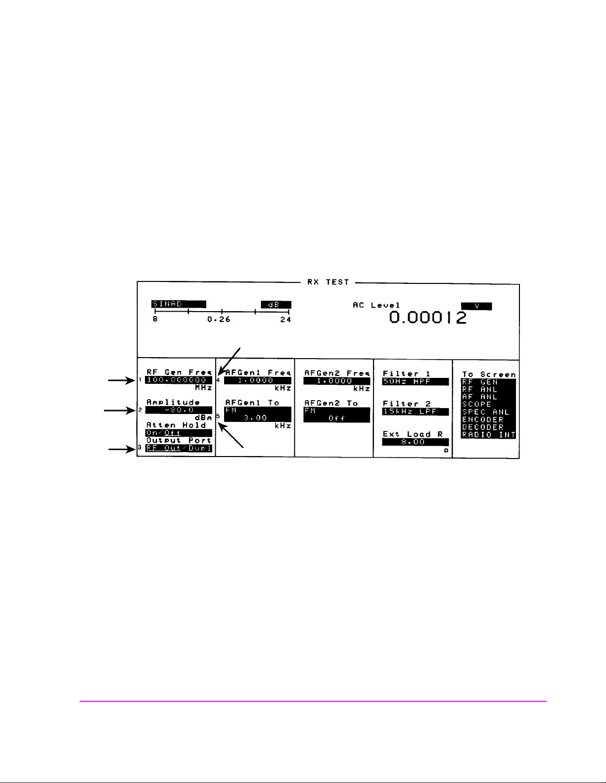
Changing A Field’s Setting
There are several types of CRT display fields in the Test Set. This section
describes some of the different types of fields.
Chapter 1, Get Started
Changing A Field’s Setting
3
Figure 3 Different Types of Fields
1
rxscrn.wmf
intro4.wmf
542
43

Chapter 1, Get Started
Changing A Field’s Setting
Unit-of-Measure Field
Unit-of-measure can be changed to display measurements in different values or
magnitudes. See item 1 in
To change a unit-of-measure
1. Position the cursor at the unit field on th e display.
2. Press a key labeled with a different unit-of-measure (such as W).
If the new units are valid, the measurement value is displayed in the unit.
Underlined Immediate-Action Field
Underlined immediat e act ion f ield s provid e a c hoi ce of two s ett ings. See i te m 2 in
Figure 3 to see an example of an underlined immediate-action field.
To change an underlined entry
1. Position the cursor at the field.
2. Push the CURSOR CONTROL knob or the ENTER key to move the underline under
the desired choice.
Figure 3 to see an example of a units-of-measure field.
The underlined setting is immediately activated when selected .
44
S:\agilent\8920\8920b\USRGUIDE\BOOK\CHAPTERS\getstart.fb

One-of-Many Field
Numeric-Entry Field
Chapter 1, Get Started
Changing A Field’s Setting
One-of-many fields disp la y a li st of choices when selected. See i te m 3 in Figure 3
to see an example of a one-of many field.
To make a one-of-many choice
1. Position the cursor at the field.
2. Push the Cursor Control knob or the ENTER key to display the choices.
3. Move the cursor through the choices by turning the knob.
4. Push the Cursor Control knob or the ENTER key to make the choice.
The choice is immediately activated when selected.
The To Screen menu (see item 5 in Figure 3) is a variation of the one-of-many
field.
Numeric-entry fields con tain values for settings l ike External Load Resistance a nd
RF Generator Frequency.See item 4 in
Figure 3 to see an example of a numeric-
entry field.
To change a value
1. Position the cursor at the field.
2. Key in the desired number using the DATA keys.
3. Press ENTER to select the choice.
OR
1. Position the cursor at the field.
2. Push the Cursor Control knob to highlight the desired choice.
3. Turn the knob to increment or decrement the value.
4. Push the Cursor Control knob or the ENTER key to select the choice.
45

Chapter 1, Get Started
How do I Verify that the Test Set is Operating Properly?
How do I Verify that the Test Set is Operating Properly?
If your Test Set powers-up and displays the RX TEST screen, but you suspect an
instrument problem, use the Instrument Quick Check to verify operation of the
basic instrument functions.
If no failure is indicated by this test, but you still suspect a problem, refer to the
“Performance Tests” infor m ation in the Assembly Level Repair Manual.
Instrument Quick Check
1. Set up the quick check:
a. Connect a cable between the DUPLEX OUT and ANT IN ports.
b. Turn instrument power on (if it is not already on).
c. Press PRESET.
d. Press DUPLEX to access the DUPLEX TEST screen.
e. Set the Tune Mode field to Manual
f. Set the Tune Freq field to 825 MHz.
g. Set the Input Port field to Ant.
h. Set the RF Gen Freq field to 825 MHz.
i. Set the Amplitude field to -10 dBm.
j. Set the Output Port field to Dupl
k. Verify that AFGen1 Freq is s e t t o 1.0000 kHz, and that AFGen1 To is set to
FM and 3.00 kHz.
l. Set the AF Anl In field to FM Demod.
m. Set the Filter 1 field to 300Hz HPF.
n. Set the Filter 2 field to 3kHz LPF.
o. Verify that De-Emphasis is Off
p. Set the Detector field to Pk+-/2.
q. Turn the VOLUME knob clockwise until you hear a tone (1 kHz default for
AFGen1 Freq).
.
.
.
2. Check the following readings:
❒ SINAD should be >35 dB.
❒ FM Deviation should be about 3.0 kHz.
3 Access the OSCILLOSCOPE screen using the To Screen menu. With the default
Vert/div setting of 2 kHz and a default Time/div setting of 200 µs, you s hould
see two complete sinewaves across the screen.
4 Access the SPECTRUM ANALYZER
an 825 MHz FM carrier.
1. Optional on some Test Set models.
46
S:\agilent\8920\8920b\USRGUIDE\BOOK\CHAPTERS\getstart.fb
1
using the To Screen menu. You should see

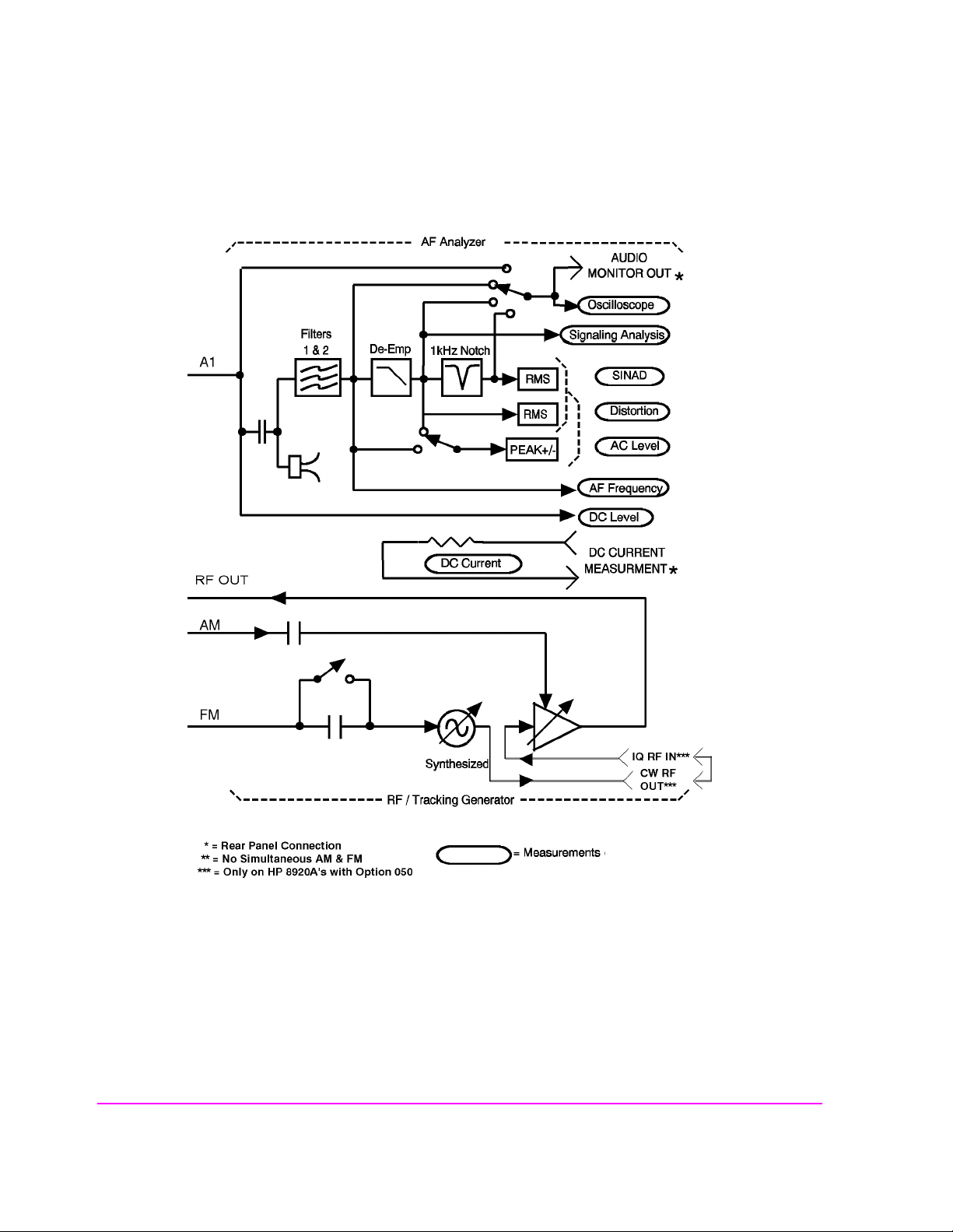
Instrument Functional Diagram
Chapter 1, Get Started
Instrument Functional Diagram
Figure 4 Instrument Functional Diagram (1 of 2)
47
Chapter 1, Get Started
Instrument Functional Diagram
intr-bd2.wmf
Figure 5 Instrument Functional Diagram (2 of 2)
48
S:\agilent\8920\8920b\USRGUIDE\BOOK\CHAPTERS\getstart.fb

2
Configuring Your Test Set
The CONFIGURE and I/O CONFIGURE screens contain a num ber of s ettings used to
alter instrument operation and hardware communication settings. The GPIB address,
screen intensity, serial communication parameters, and several other settings, are changed
in these screens.
Most CONFIGURE and I/O CONFIGURE screen entries are saved when the instrument
is turned off.
49

Chapter 2, Configuring Your Test Set
General Operating Information
General Operating Information
The following configuration information discusses general operating information
for some of the fields in these screens.
To Set Screen Intensity
1. Access the CONFIGURE screen.
2. Select the Intensity field.
3. Rotate the knob to change the setting (1=dim, 8=bright).
To Set RF Voltage Interpretation (50 /emf)
1. Access the CONFIGURE screen.
2. Position the cursor in front of the RFGen Volts field.
3. Press the Cursor Control knob or press ENTER to select 50 ohm or emf.
Ω
Voltage settings can contro l eit her :
• the voltage across a 50-ohm load, or
• the open circuit voltage (emf).
This setting affects the RF Generator’s and the Tracking Generator’s amplitudes.
To Set the Date and Time
1. Access the CONFIGURE screen.
2. Select the Date field and use the DATA keys to enter the date in the fo rmat shown b e-
low the field.
3. Select the Time field and use the DATA keys to enter the time in the format shown
below the field.
The Test Set has a built-in clock that keeps track of the date and time. It is
powered by an internal battery to keep it operating when the instrument is off.
50
S:\agilent\8920\8920b\USRGUIDE\BOOK\CHAPTERS\configts.fb

To Change the Beeper Volume
1. Access the CONFIGURE screen.
2. Select the Beeper field to dis play the volume choices.
3. Select the desired choice.
The beeper alerts you to important operating and measurement conditions. It
beeps any time a message is displayed at the top of the screen. These messages
warn you of condition s such as exc eeding the RF input level or t rying to set a fi eld
to an unacceptable value. The refore, it is rec ommended that you do no t dis able the
beeper .
To Verify or Change the Low-Battery Setting
1. Access the CONFIGURE screen.
Chapter 2, Configuring Your Test Set
General Operating Information
2. The current time setting is shown under the Low Battery field.
3. Select that field to display a list of setting choices.
• Select the desired time, or
• Select Disable to eliminate the low-battery warnin g.
The low-battery warning system is used to alert you when you have not used any
front-panel controls within a specified amount of time. This setting is only used
with DC power. It does not actually monitor the DC supply voltage. Since
batteries are most often used for a DC supply, this function helps you conserve
power by reminding you that the Test Set is still turned on.
When the specified time ha s elapsed between front-pan el entries, the Beeper
sounds and a message appears at the top of the screen alerting you to the
condition.
This setting is saved when the instrument is turned off.
51

Chapter 2, Configuring Your Test Set
General Operating Information
52
S:\agilent\8920\8920b\USRGUIDE\BOOK\CHAPTERS\configts.fb

3
Operating Overview
The information in this section discusses some frequently used operating features
of the Test Set.
From reading
• What “fields” and “screens” are.
• How to use the Cursor Control knob to select different fields and screens.
Chapter 1, “Get Started,” you should understand:
53
Chapter 3, Operating Overview
Interaction Between Screens
Interaction Between Screens
Most fields operate globally; changing the setting in any screen automatically
changes th at setting in all screens where it is available.
example of this field type.
AFGen1 Freq is an
Figure 6 Example of How Global Fields Work
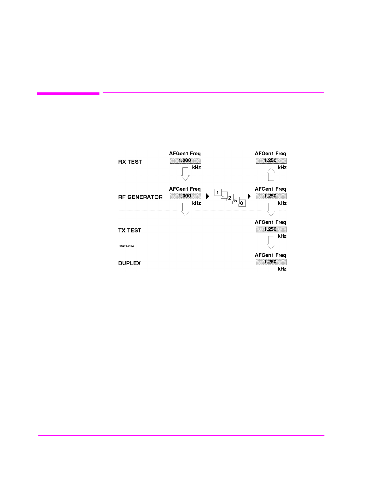
Priority fields give the RX TEST and TX TEST screens priority control of their
settings. No matter what these fields were set to in other screens, if the RX TEST
or TX TEST screen is accessed, the field changes to whatever it was last set to in
these screens. The RF Generator’s
Amplitude field is an example of this field
type. These fields and their preset values are listed in
54
S:\agilent\8920\8920b\USRGUIDE\BOOK\CHAPTERS\opoverv.fb
Table 4.

Chapter 3, Operating Overview
Interaction Between Screens
Table 4 Priority RX TEST an d TX T ES T Field s
Priority Field RX TEST TX TEST
RF Gen Amplitude Presets to −80 dBm (changeable) Always Off
AFGen1 To Presets to FM (changeable) Always Audio Out
AF Anl In Always Audio In Presets to FM Demod (changeable)
Detector Always RMS Presets to Pk +− Max (chang eable)
De-emphasis Always Off
AF Anl Measurement Presets to SINAD (changeable) Presets to Audio Freq (changeable)
Presets to 750 (changeable)
µs
Using your Test Set, duplicate the steps in Figure 7 to demonstrate how the
Priority fields operate.
55

Chapter 3, Operating Overview
Interaction Between Screens
fig2-2.wmf
Figure 7 Example of How Priority Fields Work
56
S:\agilent\8920\8920b\USRGUIDE\BOOK\CHAPTERS\opoverv.fb
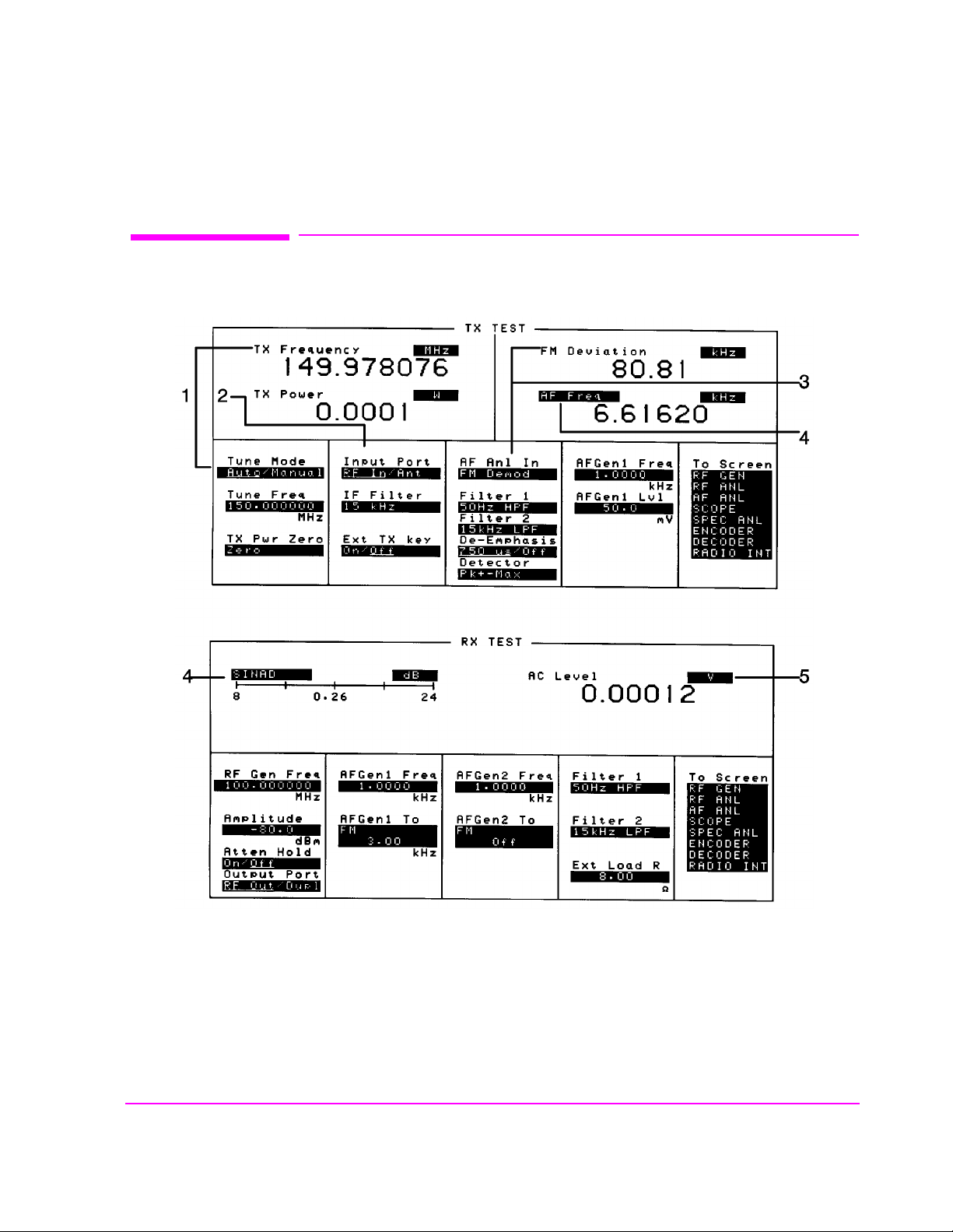
Displaying Measurements
Chapter 3, Operating Overview
Displaying Measurements
Figure 8 Where To Access Measurements
scntxrx.wmf
57

Chapter 3, Operating Overview
Displaying Measurements
Displaying RF Measurements
Transmitter Frequency
TX Frequency
Figure 8 on page 57.)
in
Transmitter Frequency Error
TX Freq Error
Figure 8 on page 57.)
(1) in
Transmitter Power
TX Power
RF In (Refer to item (2) in Figure 8 on page 57). If Ant (antenna) is selected, the
is displayed when Tune Mode is set to Auto. (Refer to item (1)
is displayed when Tune Mode is set to Manual. (Refer to item
is only measured and displayed here when the Input Port is set to
measuremen t is replaced by four dashes (- - - -).
You can measure low power levels on the ANT IN port using the Spectrum
Analyzer.
1
Refer to “TX Power” on page 511 and “TX Pwr Zero” on page 512 for more
information on measuring transmitter power.
CAUTION: Connecting a signal of >200 mW to the ANT IN (antenna) port can cause instrument damage
(although internal protection circuits can typically withstand a short-duration signal of 1 or 2
Watts). If the overpower circuit is triggered, remove the signal from the ANT IN port and turn
the Test Set off and on to reset it.
1. Optional on some Test Set models.
58
S:\agilent\8920\8920b\USRGUIDE\BOOK\CHAPTERS\opoverv.fb

Displaying AF Measurements
FM Deviation, AM Depth, AC Level
The AF Anl In set ting deter mines th e AF Analyzer’ s input and the measu rement
displayed in the top-right corner of the measurement area (see
measurements are available in the TX TEST, DUPLEX TEST , RF GENERATOR,
RF ANALYZER, and AF ANALYZER screens. (Refer to item (3) in
page 57
Table 5 AF Measurements Selected by AF Analyzer Input Setting
.)
Measurement AF Anl In Setting
FM Deviation FM Demod, FM Mod
Chapter 3, Operating Overview
Displaying Measurements
Table 5). These
Figure 8 on
AM Depth AM Demod, AM Mod
AM Depth
a. AC Level is also measured in the RX TEST screen, but
a
always uses the AUDIO IN connector as the input. (Refer
to item (5) in Figure 8 on page 57.)
SSB Demod, AudioIn, Radio Int,
Ext Mod, Mic Mod, Audio Out
59

Chapter 3, Operating Overview
Displaying Measurements
SINAD, Distortion, SNR, AF Frequency, DC Level, DC Current
Selecting the curre ntly-displ ayed measureme nt causes the To Screen menu to be
replaced by a list of measurement choi ces. Select the ne w choice to replace the old
measurement. These measurements are available in the RX TEST, TX TEST,
DUPLEX TEST, RF GEN ERATOR, RF ANALYZER, and AF ANALYZER
screens. ( Refer to item (4 ) in
Figure 8 on page 57)
The Distortion measurement is only for a 1 kHz tone.
The SINAD measurement is normally shown using an analog-type meter and
small digits, but can be changed to display in large digits only. (See
Analog METER Format” on page 62
.)
“To Use the
DC Current can only be measured using the rear-panel DC CURRENT
MEASUREMENT connections.
1
Selecting SNR (Signal/Noise Ratio) turns off the other audio measurement. For
more information on making this measurement, see
AF Power
“RF Gen Freq” on page 451.
AF Power is measured in the RX TEST screen by specifying the external load
resistance,
Ext Load R, and changing the unit of measure for the AC Level
measurement to W (Watts), mW, or dBm. (The milliwatt (mW) unit is selected by
pressing SHIFT, ENTE R ) Refer to item (5)
Figure 8 on page 57.
1. Optional on some Test Set models.
60
S:\agilent\8920\8920b\USRGUIDE\BOOK\CHAPTERS\opoverv.fb

To Change the Measurement’s Unit-of-Measure
1. Position the cursor in front of the present unit-of-measurement.
2. Press the key labeled with the desired unit.
All measurements allow you to change the associated unit-of- measure. For
instance; the
changed to display in mW, dBm, V, mV, or dB
Select mW by pressing SHIFT, ENTER.
For example; to display transmitter power in units of dBm instead of Watts:
1. Move the cursor in front of the unit-of-measure for the TX Power measurement (W).
2. Press the dBm key . The measuremen t value is changed imm ediately to display in dBm.
TX Power measurement is usually displayed in Watts, but can be
Chapter 3, Operating Overview
Displaying Measurements
µV.
61

Chapter 3, Operating Overview
Displaying Measurements
To Use the Analog METER Format
To display measurement results using the analog meter format, use the following
procedure.
1. Position the cursor in front of the unit-of-measure for the measurement you want to display.
2. Press and release the SHIFT key, then the INCR SET key to display the Meters menu
in the lower-right corner of the screen.
3. Select On/Off to display the meter.
4. Repeat steps 1 and 2 to enter each meter end point and the meter intervals.
5. Repeat steps 1, 2, and 3 to cancel the METER function.
The METER function displays an equivalent analog display. (This is the SINAD
measurement’s default state when the instrument is turned on or preset). As the
measurement is displayed graphically on the meter, the value is also displayed in
small digits below the meter.
You can specify the high and low end points and display interval, or you can use
the default meter settings.
This function is only available for measurements displayed using the large digits,
such as the measurements displayed in the RX TEST and TX TEST screens.
To Make Beat Frequency Measurements
1. Select the DUPLEX TEST screen to set up for beat frequency oscillator measurements.
2. Set the AF Anl In field to SSB Demod.
3. Manually adjust the Tune Freq field to the desired carrier frequency.
62
S:\agilent\8920\8920b\USRGUIDE\BOOK\CHAPTERS\opoverv.fb

Entering and Changing Numbers
Values for numeric entry fields can be entered and changed using various
methods, depending on your testing needs . The unit-of-measure fo r some of these
fields can also be changed (such as changing the RF Generator’s
units from dBm to
To Enter Numbers
1. Position the cursor in front of the numeric entry field to be changed.
2. Use one of the following methods:
a. enter the number and unit-of-measure directly using the keypad,
or
b. press the Cursor Control knob or ENTER to highlight the field, and use the
knob,
µV).
Chapter 3, Operating Overview
Entering and Changing Numbers
Amplitude
or
c. use the down-arrow or the up-arrow keys to in crement or decrement the present
value.
Decimal Values
Decimal values are us ed for most numeric ent r y f ie lds, such as the RF Gen Freq
setting. The acceptabl e en tr ies for decimal values ar e 0 t hr ough 9, ., +/-, and EEX.
The +/- key is used for entering negative numbers. For example; when entering
the RF Gene rator
−47 dBm: +/- 4 7 dBm.
Amplitude you can enter this sequence to set the value to
The EEX key can be used when entering exponential notation. For example; to
3
× 10
enter 1.25
kHz you could use the sequence: 1 . 2 5 EEX 3 kHz.
63

Chapter 3, Operating Overview
Entering and Changing Numbers
Hexadecimal Values
Hexadecimal (Hex) values are used for entering some signaling parameters in the
ENCODER, such as AMPS
communications parameters, such as the RADIO INTERFACE
field. The acceptable entries for decimal values are 0 through 9 and A through F.
No unit-of-measure is associated with these values.
Hexadecimal values are either entered from the keypad (A through F are shifted
functions), or by using the
selected (such as the AMPS
To Enter and Change the Unit-of-Measure
Entering the Unit-of-Measure for Settings
When a number is entered, the unit-of-measure is either specified or implied.
Filler data field, and for specifying remote
Output Data
Choices menu displ ayed when certain fields are
Filler field).
When the unit is implied, the current unit is used. For example; if the present RF
frequency is 250 MHz, and you want to change it to 225 MHz, you would enter
this sequence: 2 2 5 ENTER.
When the unit i s specif ied, the units c hange t o whatever you s pecify. For example;
if the present
RF Gen Freq setting is 250 MHz, and yo u want to change i t to 4 55
kHz, you would enter this sequence: 4 5 5 kHz.
Changing the Unit-of-Measure for Settings
T o chang e the prese nt unit- of-mea sure, posit ion the c ursor in f ron t of the f ield and
press the key labeled with the desired unit. For example, position the cursor in
front of the
RF Gen Freq field and push GHz or kHz to display the setting in
either of these units.
64
S:\agilent\8920\8920b\USRGUIDE\BOOK\CHAPTERS\opoverv.fb

To Change the Increment or Decrement Setting
Using the Pre-Defined Increment/Decrement Keys
The INCR ×10] and INCR ÷10] keys change the increment/decrement value by a
factor of 10.
Chapter 3, Operating Overview
Entering and Changing Numbers
For example; if the
the knob or push of the down-arrow or up-arrow keys, pushing INCR
Tune Freq presently changes by 10 MHz for every click of
×10] once
changes the increment va lue to 100 MHz.
Specifying An Increment Value
The INCR SET key is used to assign a specific increment value. The increment
value may use different units than the field you are incrementing/decrementing.
For instance ; if the RF Generator
Amplitude setting is displayed in dBµV, you
could increment in units of dB or mV.
To change the increment value;
1. Move the cursor to the numeric entry field to be changed.
2. Press INCR SET, and enter the desired value and u nit-of-measure using the DAT A keys.
3. Use the down-arrow and up-arrow keys or CURSOR CONTROL knob to change the
field’s value by the increment value you set.
Example of Setting an Increment Value
This example changes the Tune Freq in increments of 15 MHz.
1. Access the TX TEST screen and position the cursor in front of the Tune Freq field.
2. Press 1 0 0 MHz to set the frequency at 100 MHz.
3. Press INCR SET 1 5 MHz.
4. Turn the Cursor Control knob. The field’s value changes by 15 MHz for each knob
click.
65

Chapter 3, Operating Overview
Printing A Screen
Printing A Screen
To Print A Screen’s Contents
1. Connect a printer to the appropriate rear-panel connector.
2. Access the PRINT CONFIGURE screen from the More menu and set the Printer
Port field to the appropriate type of printer connection.
• If HP-IB is selected, enter the GPIB Printer Address of the printer.
3. Select the type of printer you are using in the Model field. If your printer is not list ed,
configure your printer to emulate one that is listed .
4. Enter a Print Title using the knob, if desired. This text will appear at the top of
your printout.
5. Display the screen you want to print and press and release the SHIFT key, then the
TESTS key to access the PRINT function.
To interrupt pr inting, select th e Abort Print field on the PRINT CONFIGURE
screen.
66
S:\agilent\8920\8920b\USRGUIDE\BOOK\CHAPTERS\opoverv.fb

Using Measurement Limit Indicators
The LO LIMIT and HI LIMIT functions are used to define a measurement
“window” to alert you to measurements that are outside these limits. When limits
are assigned, Lo and/or Hi appear by the measurement.
A measurement that goes above or be low t he defined limits causes thr ee thi ngs to
happen:
1. A message appears at the top of the screen indicating a limit was exceeded.
2. The Lo or Hi indicator by the measurement flashes.
3. The Beeper beeps if it is has been enabled in the CONFIGURE screen.
Limits are helpful when you can’t watch the Test Set’s display while you are
making an adjustment on the equip ment you are test ing or re pairing. They are a lso
a convenient way of alerting you to long-term measurement drift without having
to observe the screen.
Chapter 3, Operating Overview
Using Measurement Limit Indicators
To Set A HI and/or LO LIMIT
1. Position the cursor in front of the unit-of-measure for the measurement that you are set-
ting limits for.
2. Press and release the SHIFT key, then the down-arrow key to access the LO LIMIT
function, and enter the measurement’s low-limit value and its unit-of-measure.
3. Press and release the SHIFT key, then the up-arrow key to access the HI LIMIT func-
tion, and enter the measurement’s high-limit value and its unit-of-measure.
1. The fundamental unit for the LIMITs does not have to be the same as the measure-
ment’s units. For instance; when measuring AC Level in Volts, you can set HI and LO
LIMITs in units of dBm.
1
1
67

Chapter 3, Operating Overview
Using Measurement Limit Indicators
To Reset or Remove Limits
To reset a limit that has been exceeded
1. Position the cursor in front of the measurement’s unit-of-measure.
2. Press and release the SHIFT key, then the down-arrow (or up-arrow key) to access the
LO LIMIT (or HI LIMIT) function, then press ENTER or MEAS RESET.
To remove a limit
1. Position the cursor in front of the unit-of-measure for the assigned limit.
2. Press and release the SHIFT key, then the down-arrow (or up-arrow key) to access the
LO LIMIT (or HI LIMIT) function, then press ON/OFF.
Example of Setting HI and LO LIMITs
This example sets limits for the TX Freq Error measurement. Limits are being
set to indicate if a 100 MHz carrier varies more than
± 10 kHz.
1. Position the cursor in front of the unit-of-measure for the TX FREQ ERROR measure-
ment (the default is kHz).
2. Press and release the SHIFT key, then the down-arrow to access the LO LIMIT func-
tion, then enter 1 0 kHz.
3. Press and release the SHIFT key, then the up-arrow to access the HI LIMIT function,
then enter 1 0 kHz.
68
S:\agilent\8920\8920b\USRGUIDE\BOOK\CHAPTERS\opoverv.fb

Averaging Measurements
The AVG (average) function allows you to display the average value of a number
of measurements. You enter the number of measu rement samples us ed to calculat e
and display the measurement average. This dampens the effects of rapidly
changing measurements, providing a more usable measurement display.
To Use Measurement Averaging
1. Position the cursor in front of the measurement’s unit-of-measure.
2. Press and release the SHIFT key, then the INCR ×10 key to access the AVG function.
The default number of average samples is displayed below the measurement.
• Enter the desired number of measurement samples to be used for calculating the av erage, or
Chapter 3, Operating Overview
Averaging Measurements
• Press ON/OFF to use the currently-displayed number of samples.
3. To turn averaging of f, position the cursor in front of the unit- of-measure and pr ess and
release the SHIFT key , then the INCR ×10 key to access the AVG function, then press
the ON/OFF key.
When the averaging function is first enabled, a numeric average is calculated and
displayed each time a measurement is made. This continues until the specified
number of samples is reached. From that point on, the averaging function
performs an exponential filtering operation that mimics an RC filter.
Because of the exponential response, any large measurement changes result in a
displayed value that ramps up or down to the actual measured value.
Pressing MEAS RESET clears the mea suremen t hist ory for all measu rements and
starts the averaging process over.
Example of Using Measurement Averaging
This example enables the SINAD measurement to be averaged using 25 samples.
1. Press PRESET and wait for the instrument to display the RX TEST screen.
2. Position the cursor in front of the unit-of-measure for the SINAD measurement (default
is dB).
3. Press and release the SHIFT key, then the INCR ×10 key to access the AVG function,
enter 2 5, then press the ENTER key. Avg appears below the displayed measurement
value to indicate that averaging is being used.
69

Chapter 3, Operating Overview
Setting A Measurement Reference
Setting A Measurement Reference
The REF SET function establishes a measurement reference point. This allows
you to make a direct comparison between two measurement results, or between a
measurement standard and the actual measurement results.
Referenced measurements are displayed in one of two ways, depending on the
type of measurement:
Displayed value = Measurement − Reference. The difference between the measured
value and the reference value is displayed in the same unit-of-measure.
or
Displayed value = Measurement ÷ Reference. A ratio of the measured value to the
reference value is displayed in dB.
To Use the Present Value as a Reference
Position the cursor in front of the unit-of-m easure for the measurem ent you want to set the
reference for .
1. Press and release the SHIFT key, then the INCR ÷10 key to access the REF SET func-
tion; then press enter ENTER.
2. Ref appears below the measurement.
The measurement displayed is now referenced to the measurement value present
when the reference was set.
To Set a Specific Reference
1. Position the cursor in front of the unit-of-measure for the measurement you want to set
the reference for.
2. Press and release the SHIFT key, then the INCR ÷10 key to access the REF SET func-
tion.
3. Enter a reference value.
4. Ref appears below the measurement value to indicate a reference has been set.
The measurement displayed is now referenced to the value you entered.
70
S:\agilent\8920\8920b\USRGUIDE\BOOK\CHAPTERS\opoverv.fb

Using Memory Cards
OTP (One Time Programmable) cards provide removable read-only storage. File
editing and erasure are not possible. These cards cannot be programmed by the
Test Set; they require a special memory card programmer to save files.
SRAM cards provide removable read/write memory for your files, similar to a
flexible disk. Data can be stored, re-stored, read, or erased as needed.
SRAM memory cards require a battery to maintain stored information.
Inserting and Remov ing Memory Cards
Table 6 Memory Card Part Numbers
Memory Type
Chapter 3, Operating Overview
Using Memory Cards
Agilent
Techn ol ogies
Part Number
32 kilobytes SRAM 85700A
128 kilobytes OTP 85701A
128 kilobytes SRAM 85702A
256 kilobytes OTP 85703A
256 kilobytes SRAM 85704A
512 kilobytes SRAM 85705A
512 kilobytes OTP 85706A
Figure 9 illustrates how to insert a memory card int o th e Test Set’s front panel. To
remove a memory card, simply pull it out.
The Test Set’s memory-card label is marked with an arrow that must be inserted
on the same side as the arrow shown on the front-panel slot.
71

Chapter 3, Operating Overview
Using Memory Cards
NOTE: Memory cards may be inserted and removed with the Test Set powered on or off.
Figure 9 Inserting a Memory Card
72
S:\agilent\8920\8920b\USRGUIDE\BOOK\CHAPTERS\opoverv.fb
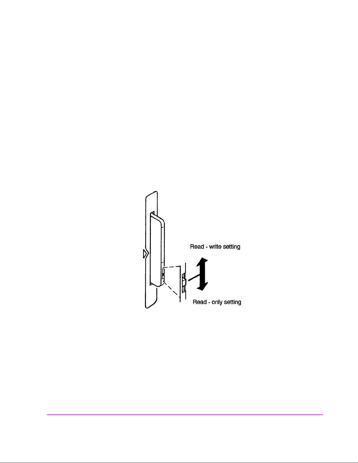
Setting the Write-Protect Switch
The SRAM memory card’s write-protect switch lets the user secure its contents
from being overwritten or erased. The switch has two positions (see
• Read-write – The memory-card contents can be changed or erased, and new files may
written on the card.
• Read-only – The memory-card contents can be read by the Test Set, but cannot be
changed or erased.
Chapter 3, Operating Overview
Using Memory Cards
Figure 10):
Figure 10 Setting the SRAM Write-Protect Switch
73

Chapter 3, Operating Overview
Using Memory Cards
The Memory Card Battery
SRAM memory cards use a lithium battery to powe r the card. Listed below ar e the
batteries for the Test Set’s SRAM cards. SRAM cards typically retain data for
over 1 year at 25
SRAM Card Battery Part Numbers - CR2016 or Agilent Technologies1420-0383
Replacing the Battery
1. Turn the Test Set on and insert the memory card. An inserted memory card takes power
from the Test Set, preventing the card’s contents from being lost.
2. Hold the memory card in the slot with one hand and pull the battery holder out with your
other hand. (See Figure 11 on page 74.)
3. Install the battery with the side marked “+” on the same side marked “+” on the battery
holder. Avoid touching the flat sides of the battery , finger oils may con taminate battery
contacts in the memory-card.
° C. To retain data, the battery should be replaced annually.
4. Re-insert the battery holder into the memory card.
5. Remove the memory card from the Test Set.
Figure 11 Replacing the Memory Card’s Battery
74
S:\agilent\8920\8920b\USRGUIDE\BOOK\CHAPTERS\opoverv.fb

Chapter 3, Operating Overview
Using Memory Cards
WARNING: Do not mutilate, puncture, or dispose of batteries in fire. The batteries can burst or explode,
releasing hazardous chemicals. Discard unused batteries according to the manufacturer’s
instructions.
Memory Card Initialization
All new SRAM cards must be initialized before they can be used to store
information. The RAM_MANAGER procedure stored on the internal ROM Disk
can be used to quickly initialize any SRAM memory card.
SRAM Memory Cards can also be initialized f rom th e TESTS screen by inser t ing
the memory card in to the front -panel slot and selec ting t he Save /Delet e f ield, then
selecting
on screen instructions to complete the process.
Init Card or pressing the k3 USER key t o init iali ze a ca rd. Foll ow the
If the error mes sage
ERROR 85 Medium uninitialized appears on the scree n
the memory ca rd has not been properly initialized. Check the SRAM bat tery to
ensure that it’s charged and inserted correctly in the battery holder.
75

Chapter 3, Operating Overview
Saving and Recalling Instrument Setups
Saving and Recalling Instrument Setups
The SAVE and RECALL functions allow you to store different instrument setups
and retriev e them later, eliminating the task of re-confi guring the Test Set.
The number of available sa ve regist ers dep ends on how many chan ges were made
to the base instrument setup for each save. (Se e
smaller the number of changes, the g reater the number of save registers that can
be used (typically over 200).
Save/Recall register settings can be saved to several types of mass storage. This
allows you to “back up the settings in case you need to clear them from memory
“Memory Considerations” on page 79) for running large programs, or when a
(see
firmware upgrade is performed (see
“BASE Settings” on page 79.) The
“Save/Recall” on page 393).
To Save an Instrument Setup
Use the More menu to access the I/O CONFIGURE screen. )
1. Select the storage media using the Save/Recall field. (The default is internal mem-
ory.
2. Make any changes to the instrument that you want to save in a register.
3. Press and release the SHIFT key then the RECALL key to access the SAVE function.
4. Use the DA TA keys or the Save menu at the bottom right of the screen to enter the reg-
ister’s name.
To Recall an Instrument Setup
Use the More menu to access the I/O CONFIGURE screen.
1. Select the media to recall settings from using the Save/Recall field. The default is
internal memory.
2. Press RECALL.
3. Use the knob to select the desired setup to be recalled from the Recall menu at the
bottom-right of the screen.
76
S:\agilent\8920\8920b\USRGUIDE\BOOK\CHAPTERS\opoverv.fb

Example of Saving and Recalling an Instrument Setup
This example SAVES changes made to the RX TEST scree n, and the n RECALLS
them. The register is saved to wherever the
memory - unless you have changed it).
1. Access the RX TEST screen and set the RF Gen Freq to 500 MHz.
2. Set Amplitude to -35 dBm.
3. Press and release the SHIFT key then the RECALL key to access the SAVE function.
A prompt appears at the top of the screen asking you to enter a name.
4. Using the DATA keys, press 1 2 3 ENTER to assign a name to these changes.
5. Press PRESET and wait for the instrument to return to normal operation.
6. If not already displayed, access the RX TEST screen. Notice that the RF Gen Freq
and Amplitude settings are reset to their preset values.
7. Press RECALL 1 2 3 ENTER. The RF Gen Freq and Amplitude are changed to
the settings you saved in register 123 (500 MHz and -35 dBm).
Chapter 3, Operating Overview
Saving and Recalling Instrument Setups
Save/Recall field is set (internal
To Remove (Clear) an Individual Save Register
Specify where the register is stored using the Save/Recall field on the I/O CONFIGURE screen.
1. Press RECALL.
2. Use the knob to position the cursor in front of the register to be removed from the Re-
call menu at the bottom-right of the screen. The register name and percentage of
memory occupied by that register are indicated at the top of the screen.
3. Press ON/OFF. A prompt appears, asking if you want to delete the save register.
4. Press YES.
77

Chapter 3, Operating Overview
Saving and Recalling Instrument Setups
To Clear All Save Registers
1. Press RECALL.
2. Use the knob to position the cursor in front of the *Clr All* entry in the Recall
menu at the bottom-right of the screen.
3. Press the knob or press ENTER. A prompt appears at the top of the screen to verify that
you want to clear all registers.
4. Press YES.
Register Names
You can use any number, letter, or combination of numbers and letters as a name
for storing instrumen t settin gs. For inst ance; if yo u want to save a set up for tes ting
a “Vulcan7” radio, you can save the setting as “VULCAN7”.
Two register names are reserved for special purposes: POWERON and BASE.
POWERON Settings
When the Test Set is turned on, it uses a set of instrument setup parameters
specified at the time of manufacture. You can have the instrument power up in a
different state by making the desired changes to the original settings, and then
saving them using the name POWERON.
The next time the instrument is turned on, the instrument returns to the state
present when you saved the POWERON setting. For instance; if the
OSCILLOSCOPE screen was displayed when POWERON was saved, it is the
screen that is displayed when you turn the instrument on.
78
S:\agilent\8920\8920b\USRGUIDE\BOOK\CHAPTERS\opoverv.fb

Chapter 3, Operating Overview
Saving and Recalling Instrument Setups
BASE Settings
The BASE register contains any field settings the user has saved that are different
from the instrument preset state. It establishes a reference point for all future
saves. If a base is not saved, the preset state is used as the reference.
When you save an instrument setup, the new setup is compared to the base
settings, and any differences are stored under the register name you supply.
Because only differences are stored, a much larger number of instrument setups
can be saved than if the contents of every field was saved.
When you recall an ins trument se tting, every fi eld is re set to the base se ttings. Th e
saved settings are then used to re-establish the desired instrument setup.
CAUTION: Since each save/recall register only contains the differences between the setup being saved and
the present base register settings, changi ng the bas e settin gs causes all ot her sav ed setup s to be
erased from memory (including the POWERON setting if one has been saved).
Unless you consistently change the same fields to the same value each time you use the
instrument, you should avoid creating your own BASE settings.
Memory Considerations
When the Save/Recall field of the I/O CONFIGURE screen is set to
Internal, programs are saved to the same non-volatile RAM used to create
RAM Disk(s) and run IBASIC pro gra ms. By saving a larg e nu mb er of instrument
setups, you reduce the amount of RAM available to run programs. If you get a
“memory overflow” message while trying to load a program, you must clear one
or more save/recall registers to free RAM space.
Instrument Hardware Changes
Recalling a saved register that uses a hardware option that has been removed
(such as an audio filter) results in unspecified operation. Re-install the needed
option befor e attempting to recall the associated register(s).
79

Chapter 3, Operating Overview
Using USER Keys
Using USER Keys
User keys instantly access instrument settings without using the knob. You can
use user keys to move quickly between fields on the same screen, and to access
field settings that are not normally available on the screen you are using.
Local user keys ar e u sed to move between se ttings on the screen that is displayed.
When the user key is pressed, the cursor instantly moves to, and selects, the
assigned field; eliminating the need to turn and push the knob. Five local user
keys are available for each screen: k1, k2, k3, k4, and k5.
Five factory-as si gned local user keys a re available in each screen; however, using
these keys removes any other local user keys you may have already set up.
Global user keys are used to access settings that are not available on the current
screen. Three global user keys are available: k1’, k2’, and k3’. (These are shifted
functions of the local user keys.)
When defining user keys, the ASSIGN function is used to create key definitions;
the RELEASE function removes the definitions. Re-assigning a user key to a
different field setting automatically releases it from the setting it was previously
associated with.
80
S:\agilent\8920\8920b\USRGUIDE\BOOK\CHAPTERS\opoverv.fb
To Use the Pre-Assigned Local USER Keys
1. Press and release the SHIFT key, then the k4 key to access the ASSIGN function; then
press the ENTER key. The n umb ers 1 through 5 appear in f ront of various fields. (See
Figure 12.)
2. Press the different local user keys (k1 to k5) and notice how the cursor immediately
moves to the corresponding field.
3. To stop using the default local user keys, press and release the SHIFT key, then the k5
key to access the RELEASE function; then press the ENTER key.
Chapter 3, Operating Overview
Using USER Keys
Figure 12 An Example of Pre-Assigned Local User Keys
scnusr.wmf
81

Chapter 3, Operating Overview
Using USER Keys
To Assign Local USER Keys
1. Move the cursor to the field you want to assign a local user key to.
2. Press and release the SHIFT k ey , then the k4 key to access the ASSIGN function. Then
press a local USER key (k1-k5) . The user key nu mber appears in front of the field you
assigned it to.
Example of Assigning a Local USER Key
Use this example to assign local USER key k1 to the Filter 1 field in the RX
TEST screen.
1. Access the RX TEST screen and position the cursor in front of the Filter 1 field.
2. Press and release the SHIFT key, then the k4 key to access the ASSIGN function ; then
press k1. A small 1 appears next to the field indicating that USER key k1 has been assigned to it.
3. Move the cursor to any other field on the screen and press k1 . Th e cursor immediately
returns to the Filter 1 field. The field is also highlighted to change the entry using
the CURSOR CONTROL knob or arrow keys.
To Release Local USER Keys
1. Display the screen containing the user key assignment to be removed.
2. Press and release the SHIF T key , th en the k5 key to access the RELEASE f unction; then
press the USER k ey (k1-k5).
82
S:\agilent\8920\8920b\USRGUIDE\BOOK\CHAPTERS\opoverv.fb

To Assign Global USER Keys
1. Move the cursor to the field you want to assign a global user key to.
2. Press and release the SHIFT k ey , then the k4 key to access the ASSIGN function. Then
press SHIFT and a global USER key (k1’ - k3’). Unlike a local user key, the user key
number does not appear at this field; instead, a prompt appears at the top of the screen
confirming the key assignment.
Example of Assigning a Global USER Key
Use this example to assig n glob al USER ke y k1’ to the AF Anl In field, and then
access this field from the OSCILLOSCOPE screen.
1. Access the AF ANALYZER screen and position the cursor in front of the AF Anl In
field.
2. Press and release the SHIFT key, then the k4 key to access the ASSIGN function.
Chapter 3, Operating Overview
Using USER Keys
3. Press SHIF T, k1’. Notice the prompt Global User key 1 assigned. at the top
of the screen.
4. Access the OSCILLOSCOPE screen.
5. Press SHIFT, k1’.
AF Anl Input
present input is set to FM Demod). To change the input, use the arrow keys
(down-arrow or up-arrow), or press ENTER to access the
A field that is accessed using a global user key is only displayed at the top of the
screen while it is being accessed. Moving the cursor to any other field in the
screen causes the user key field to disappear until it is accessed again.
To Release Global USER Keys
1. Move the cursor to the field with the global user key assigned to it.
2. Press and release the SHIFT key, then the k5 key to access the RELEASE function.
Then press SHIFT and the USER key to be released (k1’-k3’).
, FM Demod is displayed at the top of the screen (assuming the
Choices menu.
83

Chapter 3, Operating Overview
Setting an RF Generator/Analyzer Offset
Setting an RF Generator/Analyzer Offset
You can set a fixed frequency offset between the RF Generator and the
RF Analyzer. This feature is convenient for testing radios with a fixed
transmit/receive frequency offset.
To Set an RF Offset
1. Access the CONFIGURE screen.
2. Position the cursor in front of the RF Offset field, and press the Cursor Control knob,
or press ENTER to turn the offset On or Off.
3. Select the (Gen)-(Anl) field and enter the frequency offset value.
Example of Setting an RF Offset
1. Access the CONFIGURE screen.
2. Set the RF Offset to On.
3. Enter an offset frequency ((Gen)-(Anl)) of 10 MHz.
4. Access the DUPLEX screen.
5. Set the Tune Mode to Manual.
6. Select the RF Gen Freq field, and rotate the Cursor Contro l knob to vary the RF Gen -
erator’s frequency.
7. Notice that the Tune Freq value changes to maintain the 10 MHz difference between
the generator and the analyzer.
1
1. Manual tuning is used in this example to prevent possible unexpected Tune
Frequency changes during the procedure.
84
S:\agilent\8920\8920b\USRGUIDE\BOOK\CHAPTERS\opoverv.fb

Using Remote Control
The Test Set can be remotely controlled several ways:
• Using GPIB control from a computer/controller.
• Using IBASIC programs on memory cards.
• Using an ASCII terminal connected to the serial port.
Using GPIB Control
The Pr ogr ammer’s Guide contains inform ation on wri ting GPIB contr ol progr ams
for the Test Set. Programming examples and a syntax listing provide general
GPIB operation guidelines.
Chapter 3, Operating Overview
Using Remote Control
Running IBASIC Programs from Memory Cards
The documentation shipped with Agilent Technologies11807 software packages
explains how to run those programs from memory cards. Refer to the
Programmer’s Guide for detailed information on using memory cards with y our
own IBASIC programs.
85

Chapter 3, Operating Overview
Using Remote Control
Using an ASCII Terminal
Connecting an ASCII terminal to the serial port allows you to remotely operate
the Test Set by entering characters that represent each front-panel control.
Before you can use this feature, you must first set the required serial port settings
in the I/O CONFIGURE screen, and make any hardware connections.
The Serial Port connections are described in
Knob Descriptions.”
To Configure for Serial Port Operation
1. Access the I/O CONFIGURE screen.
2. Set the Serial In field to Inst.
3. Set the IBASIC Echo field to On.
4. Set the Inst Echo field to On.
5. Set the remaining serial communications fields according to your terminal/computer’s
serial communication requirements. These fields include:
• Serial Baud
• Parity
• Data Length
• Stop Length
• Rcv Pace
• Xmt Pace
6. The Test Set now responds to the equivalent characters sent to it by the terminal/computer.
Equivalent Front-Panel Control Characters
Table 7 on page 3 87
.
lists the terminal/computer keystrokes that equate to front-
Chapter 24, “Connector, Key, and
panel controls. Each sequence must be preceded by the Escape key.
For example, to remotely acc ess the CONFIGURE screen, pr ess the Esc key, then
press the C ke y on your term inal/computer. Be sure to use upper-case C fo r this
example.
86
S:\agilent\8920\8920b\USRGUIDE\BOOK\CHAPTERS\opoverv.fb

Ta ble 7 Equivalent Front-Panel Control Characters
Chapter 3, Operating Overview
Using Remote Control
Equivalent
Function
CANCEL ! A X
PERCENT MHZ_V ( EEX Z
S_KHZ_MV ) YES_ON_OFF [
BACKSPACE - NO_PPM_W ]
ENTER . RX a
RELEASE 0 TX b
K1 1 DUPLEX c
K2 2 PREV d
K3 3 TESTS_MAIN e
K4 4 LOCAL f
K5 5 RECALL g
K1_PRIME 6 MEAS_RESET h
K2_PRIME 7 PRESET i
K3_PRIME 8 INCR_DIV_10 j
ASSIGN 9 INCR_SET k
KNOB_TURN_CCW < INCR_TIMES_10 l
KNOB_TURN_CW > DOWN m
MSSG A UP n
HELP B SEVEN o
CONFIG C EIGHT p
HOLD D NINE q
PRINT E FOUR r
ADRS F FIVE s
SAVE G SIX t
REF_SET J ONE u
METER K TWO v
AVG L THREE w
LO_LIMIT M ZERO x
HI_LIMIT N POINT y
ESC
Character
Function
Equivalen t
ESC
Character
87

Chapter 3, Operating Overview
Using Remote Control
Ta ble 7 Equivalent Front-Panel Control Characters (Continued)
Equivalent
Function
ESC
Function
Character
E R PLUS_MINUS z
F S OHM_PCT_DEL_DBUV
B U DB_GHZ_DBM |
C V MS_HZ_UV
DW
Alternate sequences for 5 commonly-used functions are also available. Hold
down the Cntl (control) key and select the corresponding key for the desired
function. Example: Cntl H moves the cursor to the left one space.
ENTER - J or M
CANCEL - C
BACKSPACE - H
KNOB_TURN_CW - R
KNOB_TURN_CCW - L
Equivalen t
ESC
Character
88
S:\agilent\8920\8920b\USRGUIDE\BOOK\CHAPTERS\opoverv.fb

4
Adjacent Channel Power Screen
NOTE: This screen is displayed on the Test Set with Option 102, Spectrum Analyzer.
This screen is used t o measure Adj acent Channe l Power. This is a measurement of
the power of signals at a specific channel spacing above and below the RF
Analyzer’s center frequency. This screen is accessed by selecting
from the
To Screen menu.
AD CH PWR
89

Chapter 4, Adjacent Channel Power Screen
How the Test Set Measures Adjacent Channel Power (ACP)
How the Test Set Measures Adjacent Channel Power (ACP)
When you access this s creen, the Test Set automaticall y starts a multi-step pr ocess
for measuring ACP:
1. AF Generator 1 is turned off if the Carrier Ref field is set to Unmod.
2. The amplitude of the center frequency (Tune Freq) is measured to establish a
reference.
3. AF Generator 1 is turned back on if it was previously turned off.
4. The power in each of the adjacent channels is analyzed.
5. Adjacent Channel Power is calculated and displayed. This value can be displayed as an
absolute power level or as a ratio referenced to the center frequency’s level.
Which Input Port to Use. The TX Power measurement is used to calculate absolute
Adjacent Channel Power. Since TX Power can only be measured using the RF IN/OUT
port, you must use this port to measure ACP Level. ACP Ratio can be measured using
either the RF IN/OUT or the ANT IN port.
Measuring ACP on AM Transmitters. When measuring AM signals, the reference level
must be measured on an unmodulated carrier; so the Carrier Ref field must be set to
Unmod. After the reference is measured, the power in the adjacent channels must be measured with modulation. This requires the modulating signal to be turned off and on repeatedly as measurements are being calculated and displayed. Since the Test Set automatically
turns AFGen1 on and off when the Carrier Ref field is set to Unmod, you must use
AFGen1 and the AUDIO OUT port as the modulation source for making AM ACP measurements.
90
S:\agilent\8920\8920b\USRGUIDE\BOOK\CHAPTERS\acpscrn.fb
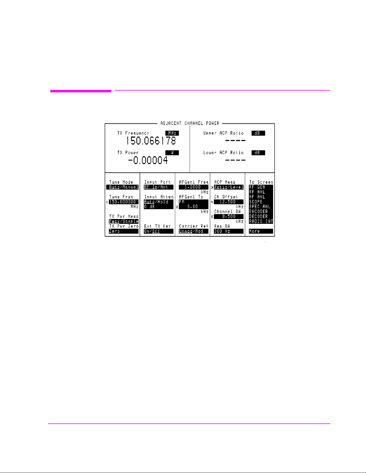
Field Descriptions
Chapter 4, Adjacent Channel Power Screen
Field Descriptions
Figure 13 The Adjacent Channel Power Screen
ACP Meas
This field selects the format for displaying upper and lower adjacent channel
power levels.
• Ratio displays the power levels relative to the power around the center frequency
(Tune Freq). Levels can be displayed in dB or as a percentage (%).
• Level displays the absolute power levels in mW, W, dBm, V, mV, and dBmV.
Operating Considerations
TX Power
Four dashes are displayed for these meas urements when the
Ant (ANT IN).
ACP Ratio can be measured on either the ANT IN port or RF IN/OUT port.
For more information, refer to
Power (ACP)” on page 90
and ACP Level can only be measured through the RF IN/OUT port.
.
adchpwr.wmf
Input Port is set to
“How the Test Set Measures Adjacent Channel
91

Chapter 4, Adjacent Channel Power Screen
Field Descriptions
AFGen1 Freq
This field sets the frequency for the first audio frequency sinewave generator.
AFGen1 To
This field sets two values:
• The upper field determines whether the AFGen1 signal modulates the RF Generator or
is output through the AUDIO OUT connector.
• The lower field sets the depth of modulati on for FM and AM in kilohert z and amplitude
(including Off) for audio out. The AUDIO OUT level is always in volts rms.
Operating Considerations
This is a priority control field. Accessing the RX TEST or TX TEST screen
overrides any changes made to this field in other screens.
Carrier Ref
Channel BW
See Also
“Interaction Between Screens” on page 54
Use the carrier reference field to indicate whether the carrier (Tune Freq) being
measured should be unmodulated or modulated when making the ACP reference
measuremen t. (For more information, refer to
Adjacent Channel Power (ACP)” on page 90
Operating Considerations
• FM transmitters can be measured with the carrier modulated or unmodulated.
• For AM transmitters, the carrier must be measured while unmodulated. AFGen1 and
the AUDIO OUT port must be used as the modulation source whenever Unmod is
selected.
“How the Test Set Measures
.)
Use the channel bandwidth field to specify the bandwidth of the carrier and
adjacent channels to be measured. (See
Figure 14 on page 93.)
92
S:\agilent\8920\8920b\USRGUIDE\BOOK\CHAPTERS\acpscrn.fb

Chapter 4, Adjacent Channel Power Screen
Field Descriptions
adchpwr1.wmf
Figure 14 Relationship Between Tune Freq, Ch Offset, and Channel BW Fields
93

Chapter 4, Adjacent Channel Power Screen
Field Descriptions
Ch Offset
Use the channel offset field to enter the frequency difference between the Tune
setting and the center of the adja cen t cha nnels you want to measure. This is
Freq
an absolute value; only positive values can be entered. See
Ext TX key
This field controls a switch at t he MIC/ACC connector. Use it to “key” an external
transmitter.
See Also
“MIC/ACC” on page 520
Input Atten
Figure 14 on page 93.
Input Attenuation sets the amount of input attenuation for the RF IN/OUT and
ANT IN connectors. This function controls two settings:
• The upper field determines if you want the instrument to set the attenuation automatically (Auto), or if you want to set the value manually (Hold).
• The lower field displays the present attenuation value, and is used to set the desired attenuation level when the upper area is set to Hold.
Operating Considerations
Input Attenuator autora ngi ng ca n int er fe re wit h os cil loscope or signaling decod er
operation under certain conditions.
See “Input Atten” on page 427 for additional
information.
94
S:\agilent\8920\8920b\USRGUIDE\BOOK\CHAPTERS\acpscrn.fb

Input Port
Chapter 4, Adjacent Channel Power Screen
Field Descriptions
This field selects the RF IN/OUT or ANT IN port for making RF measurements.
The RF IN/OUT port must be used for making TX Power or ACP Level
measurements on this screen.
Operating Considerations
Power levels for each port are printed on the Test Set’s front panel. If the RF
power at the RF IN/OUT port exceeds allowable limits, a loud warning signal
sounds and a message appears at the top of the screen. If this occurs, disconnect
the RF power, press the MEAS RESET key, and allow the Test Set to cool off for
approximately two minutes before making any other measurements on this port.
The ANT IN (antenna input) connector provides a highly-sensitive input for very
low level signals (such as “off the air” measurements). You cannot measure TX
(RF) Power or ACP Level on this screen using the ANT IN port.
CAUTION: Connecting a signal of >200 mW to the ANT IN port can cause instrument damage
(although internal pr otect ion circuits can ty picall y withs tand a s hort -durat ion s ignal of 1 o r
2 Watts).
If the overpower circuit is triggered (signified by a warning message at the top of
the screen), remove the signal from the ANT IN port, and press the MEAS
RESET key or turn the Test Set off and on to reset it.
Lower and Upper ACP [Ratio:Level]
These two measurements dis play the amount of power in sign als above and be low
Tune Freq signal. T he level is dis played as a ratio (referenced to the power
the
around the
See Also
“ACP Meas” on page 91
Tune Freq) or as an absolute value.
95

Chapter 4, Adjacent Channel Power Screen
Field Descriptions
Res BW
The resolution bandwidth field selects the IF filter used when measuring the
power of the carrier and the adjacent channels.
Operating Considerations
Using a narrower bandwidth filter (300 Hz) slows the measurement, but rejects
carrier leakage and out of channel spurs. Using a wider bandwidth filter
(1 kHz) speeds measurements, but may allow unwanted spurs and carrier leakage
to be integrated into the measurement when measuring at t he edges of the selected
channel bandwidth.
Tune Freq
This field sets the center frequency for the RF signal to be analyzed.
Tune Mode
See Also
“Tune Mode” on page 96
This field selects Automatic or Manual tuning of the RF Analyzer.
Auto tuning causes the RF Anal yzer t o fin d the si gnal wi th the great est a mplitud e
>-36 dBm, and to set the Tune Frequency for that signal.
Manual tuning requires the operator to set the Tune Frequency for the RF signal
to be analyzed.
Operating Considerations
Changing the Tune Mode also changes the RF frequency display. Automatic
tuning enables the
TX Freq Error measurement.
TX Frequency measurement. Manual tuning enables the
96
S:\agilent\8920\8920b\USRGUIDE\BOOK\CHAPTERS\acpscrn.fb

TX Freq Error/TX Frequency
This measurement displays Transmitter Frequency Error or absolute Transmitter
Frequency.
See Also
Chapter 4, Adjacent Channel Power Screen
Field Descriptions
“Tune Mode” on page 96
TX Power
Transmitter (TX) Power measures RF power at the RF IN/OUT port.
Operating Considerations
Only the RF IN/OUT port can be used for measuring TX Power on this screen.
When the
Input Port is set to Ant, four das hes (- - - -) appear in plac e of digits
for this measurement.
1
Use the Spectrum Analyzer
to measure low-level RF power (≤200 mW) at the
ANT IN port.
TX Pwr Zero
The transmitter power zero function establishes a 0.0000 W reference for
measuring RF power at the RF IN/OUT port.
CAUTION: RF power must not be applied while zeroing. Set the RF Generator screen’s Amplitude
field to off to prevent internal cross-coupling into the power detector while zeroing.
Operating Considerations
When power is applied to the RF IN/OUT connector, the temperature of the
internal circuit ry incr eases. Thi s can caus e changes in the TX Power measur ement
when low power levels are measured immediately following high power
measurements.
When alternately making high and low power measurements, always zero the
power meter immediately before making the low power measurements; this
provides the best measurement accuracy.
1. Optional on some Test Set models.
97

Chapter 4, Adjacent Channel Power Screen
Field Descriptions
98
S:\agilent\8920\8920b\USRGUIDE\BOOK\CHAPTERS\acpscrn.fb

5
AF Analyzer Screen
99
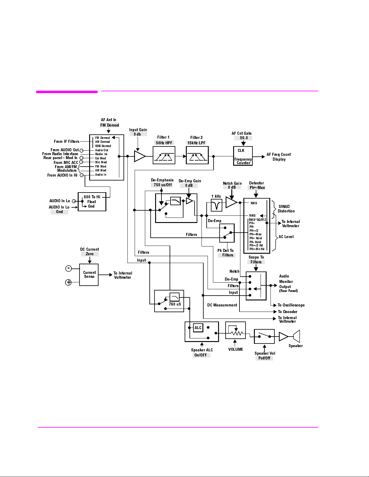
Chapter 5, AF Analyzer Screen
Block Diagram
Block Diagram
7R+L
)ORDW
*QG
'&&XUUHQW
=HUR
&XUUHQW
6HQVH
)0'HPRG
$0'HPRG
66%'HPRG
$XGLR2XW
5DGLR,QW
([W0RG
0LF0RG
)00RG
$00RG
$XGLR,Q
)URP,))LOWHUV
)URP$8',22XW
)URP5DGLR,QWHUIDFH
5HDUSDQHO0RG,Q
)URP0,&$&&
)URP$0)0
0RGXODWRUV
)URP$8',2,Q+L
$8',2,Q/R
$8',2,Q/R
*QG
-
+
$)$QW,Q
)0'HPRG
7R,QWHUQDO
9ROWPHWHU
,QSXW*DLQ
GE
)LOWHUV
,QSXW
)LOWHU
+]+3)
'H(PSKDVLV
XV2II
)LOWHU
N+]/3)
'H(PS*DLQ
G%
)LOWHUV
N+]
'H(PS
1RWFK*DLQ
G%
3N'HW7R
)LOWHUV
1RWFK
'H(PS
)LOWHUV
,QSXW
$)&QW*DWH
&/.
)UHTXHQF\
&RXQWHU
'HWHFWRU
3N0D[
506
506
5066457
3.
3.
3.
3.0D[
3.+ROG
3.+ROG
3.+G
3.0[+G
6FRSH7R
)LOWHUV
$))UHT&RXQW
'LVSOD\
6,1$'
'LVWRUWLRQ
7R,QWHUQDO
9ROWPHWHU
$&/HYHO
$XGLR
0RQLWRU
2XWSXW
5HDU3DQHO
X6
'&0HDVXUHPHQW
$/&
6SHDNHU$/&
2Q2))
Figure 15 AF ANALYZER Functional Block Diagram
1
The Settling, Gain Cntl, and Ext Load R fields are not shown.
2
Variable Frequency Notch if purchased.
100
S:\agilent\8920\8920b\USRGUIDE\BOOK\CHAPTERS\afascrn.fb
92/80(
6SHDNHU9RO
3RW2II
7R2VFLOORVFRSH
7R'HFRGHU
7R,QWHUQDO
9ROWPHWHU
6SHDNHU
 Loading...