


HP 8901B Modulation Analyzer
150 kHz - 1300 MHz
HP 11722A Sensor Module
100 kHz - 2600 MHz
Technical Specifications
• RF Power: ±0.02 dB
instrumentation accuracy
• RF Frequency: 10 Hz resolution
• AM and FM: 1% accuracy
Four Instruments In One
• fM: 3% accuracy
• Audio Characterization
AC Volts: ±4% accuracy
Frequency: 6 digits of resolution
Distortion: ±1 dB accuracy
The HP 8901B Modulation Analyzer combines four
precise measurement functions into one fully
automatic, HP-IB programmable instrument. It includes
a power meter, modulation analyzer, frequency counter,
and audio analyzer. For precise signal analysis, the
HP 8901B Modulation Analyzer provides the
performance you need, the features you want, and the reliability and serviceability you expect.
RF Power delivers the accuracy and resolution of a
high performance power meter. The HP 8901B with the
HP 11722A Sensor Module measures power from
+30 dBm to – 20 dBm at frequencies from 100 kHz
to 2.6 GHz. The HP 8901B accepts all HP 8480 series
power sensors for extended measurement
capability.
AM and FM measurements offer 1% accuracy
(3% accuracy for φM) and fast one-key operation. The
HP 8901B has extremely low internal noise, and very
low AM/φM and φM/AM conversion, for accurately
measuring residual and incidental AM, FM and φM on
a wide range of simple and complex modulated signals.
RF Frequency of complex modulated signals can be
difficult to measure, but not with the HP 8901B.
Automatically tuning to the largest input signal or to any
user specified frequency, the HP 8901B counts with
10 Hz resolution.
Audio distortion, frequency and level measurements
provide comprehensive characterization of the modulation signal.

HP 8901B Modulation Analyzer and
HP 11722A Sensor Module
In Track Mode, the Analyzer continuously tracks a swept signal. Range Hold
freezes the instrument settings at their current value.
Indicators display current HP-IB
Independently selectable
high-pass and low-pass
filters match the post-detection
bandwidth to the application.
Four standard de-emphasis
networks are available for FM
measurements. Using the
Pre-display key, the de-emphasis
networks are positioned before
the displayed measurement
circuit, to display “de-emphasized”
FM deviation.
STATUS.
Large 10- digit LED display for all
measured results and error
messages.
Store and recall instrument
settings in eight non-volatile
memory locations.
Enter RF Power calibration factors
into non-volatile memory for
automatic compensation of power
sensor efficiency and mismatch loss.
This connector has
two functions. It serves
as a recovered
modulation output for
external measurements,
or external audio input
for ac level, frequency
or distortion
measurements.
Zero the HP 11722A Sensor
Module without removing
it from the device
under test.
Accurate 1mW reference
for RF power calibration.
AM/FM calibrator provides
extremely accurate signals for
modulation calibration. AM
depth and FM deviation are
calibrated to 0.1% accuracy.
Recorder output provides a dc voltage proportional to the
measured result.
Modulation detector keys
select positive peak, negative
peak, ±peak/2, average, or
rms detectors. Peak Hold is
used with either peak detector
for measuring transients.
Selectable formats
display results in the
units desired.
Pull-out information
cards for quick reference
to instrument operation,
special functions, and
error messages.
Special function key for
complete control of
Analyzerfunctions. This key also
executes many built-in
troubleshooting routines.
The Analyzer
automatically
recognizes which
power sensor is used
and sets the appropriate
power ranges.
If using the HP 8901B
without the HP 11722A,
input circuitry is
protected from damage
for signals up to
25 watts.
Remote control output for user configured power
sensor/receiver input switch.
2
TTL level indicates Frequency Offset Mode.
HP-IB: Not just lEEE-488, but the hardware,
documentation and support that delivers the
shortest path to a measurement system.
With the HP 11722A Sensor Module, all
measurements including RF Power are made at
a single connector.

For Your Applications
Transmitter Testing
You can perform your standard transmitter measurements with the HP 8901B Modulation Analyzer. It measures transmitter output power very accurately, and it
counts frequency to 10 Hz resolution. The HP 8901B
will accurately measure the signal modulation, and
characterize the demodulated audio signal’s frequency,
level and distortion.
The HP 8901B includes many features designed for
transmitter testing, such as a Peak Hold detector for
capturing short transient modulation signals and a special Tone-Burst-Receiver Mode. Using this mode, audio
signals are captured and demodulated in <5 msec. This
is used for demodulating signalling tones sent when a
transmitter is first keyed. Because the HP 8901B may
be directly connected to the output of the transmitter,
overpower protection to 25 watts is standard.
RF Signal Characterization
The HP 8901B Modulation Analyzer is an excellent lab
and production tool for accurately characterizing RF
signals from 150 kHz to 1300 MHz.
The HP 8901B’s built-in power meter eliminates the
need for an external power meter. Unlike diode detectors, the HP 8901B’s power meter accurately measures
signals with harmonics and spurious.
Use the HP 8901B to perform residual AM and FM measurements of such low noise sources as crystal oscilla-
tors, or make accurate AM/φM and AM/AM conversion
measurements of phase and amplitude sensitive devices such as bandpass filters and multiple channel receivers. Excellent isolation between AM and FM makes
it simple to separate the AM and φM of AM stereo, incidental AM of FM transmitters and the AM, FM and φM
components of complex signals.
Automatic Test Systems
The HP 8901B is an important component of automatic
RF test systems. All functions – power measurement,
frequency count, modulation, and audio analysis – are
fully automatic and easily programmed. With these
measurements combined into one instrument, interfacing requirements, hardware costs, and software development time are reduced.
Because of its precision modulation and power measurements, the HP 8901B is a valuable tool for calibrating automatic test systems.
3

Performance You Need
RF Power: Power Meter Accuracy
The HP 8901B Modulation Analyzer performs power
measurements with superb accuracy and measurement
ease. Power meter linearity is ±0.02 dB plus ±0.02 dB
per range change. With a single key stroke the
HP 8901B automatically senses the power sensor type,
autoranges to the input signal, measures its power,
compensates for sensor flatness, and displays the results in units you choose. In addition to the
HP 11722A Sensor Module, the HP 8901B accepts all
HP 8480 series power sensors for power measurements
from -70 dBm (100 pW) to +44 dBm (25W) at frequencies from 100 kHz to 26.5 GHz.
If you change sensors, just enter the new calibration
factors into non-volatile memory, either from the keyboard or via HP-IB. You can store two complete sets of
sensor calibration factors.
The front panel Power Reference enables precise calibration of your power sensor at the reference calibration factor frequency. This 50 MHz reference is set to
1.00 mW ±0.7%, traceable to the U.S. National Bureau
of Standards.
AM, FM and fM: Superb Accuracy
Precise AM, FM, and φM measurements are a major
contribution of the HP 8901B Modulation Analyzer. Basic measurement accuracy is 1% for AM and FM and 3%
for φM. With excellent separation between the FM dis-
criminator and AM detector, incidental AM and FM
measurements are made easily and accurately.
Residual AM in a 50 Hz to 3 kHz bandwidth is less than
0.01%. The very low noise FM discriminator makes re-
sidual FM measurements of less than 1 Hz at 100 MHz
increasing linearly with frequency to less than 8 Hz at
1300 MHz.
RF Power and AM/FM calibrators
RF Frequency: High Resolution
The HP 8901B Modulation Analyzer counts all types of
modulated signals with 10 Hz resolution. The high stability reference option has an aging rate of less than
1X10⁻⁹/day. For selectively counting low level signals,
use the HP 8901B’s manual tune mode.
Audio: Built-in Convenience
The HP 8901B’s audio capabilities often eliminate the
need for external equipment when measuring demodulated signals or external audio signals. The Analyzer
counts audio frequencies with 6 digits of resolution,
measures distortion of 400 Hz and 1000 Hz signals and
measures rms levels from 100 mV to 3V with
4% accuracy.
Select from six detectors for modulation measurements. In addition to positive and negative peak detectors, the HP 8901B provides a ±Peak/2 detector, For residual noise measurements, choose from an average
responding detector which is rms sinewave calibrated
or a true rms detector. The Peak Hold detector captures and holds the maximum positive or negative peak
modulation of a signal. This is ideal for modulation limiting tests.
The AM/FM calibrator provides extremely accurate
modulated signals with ±0.1% accuracy, for easy selfcheck and re-calibration of the instrument AM and FM
calibration factors.
4

Features You Want
Single Key Measurements
The HP 8901B is very easy to use. In automatic operation, all major functions are selected with a single key.
No manual tuning or range selection is needed. The
front panel is simple, uncluttered, and easy to use.
Flexible Display Formats
The HP 8901B offers numerous data display formats.
For example, RF power can be displayed in watts, dBm,
volts, dB V, mV, dB mV, µV, and dB µV. Use the Ratio
and Log/Lin keys to display results in dB or % relative
to a measured value or a value entered from the keyboard. These features often eliminate the need for
manual calculations.
Fully Programmable
All HP 8901B functions are fully programmable via the
Hewlett-Packard Interface Bus (HP-IB). Programming
commands are easy to generate. This ease of use
coupled with the multiple functions of the
HP 8901B make it a powerful tool for system
applications.
Operation to 26.5 GHz and Beyond
For your measurement needs above 1300 MHz, use the
Frequency Offset mode in the system configuration
shown. This mode extends the HP 8901B capabilities to
microwave frequencies.
The system functions as a single instrument, making
microwave modulation, frequency, and power measurements. You control operation from the HP 8901B front
panel. When the external LO frequency must be
changed, the HP 8901B requests the external controller
to make the change. A separate non-volatile cal-factor
table is available in Frequency Offset mode for your microwave power sensor. Measurement performance is
maintained, except for the increase in residual FM and
φM noise due to the external LO.
Selectable Filters
Independently selectable high-pass and low-pass audio
filters remove undesired signals such as harmonics,
noise and spurious from the recovered modulation signal. The >20 kHz Bessel filter minimizes overshoot
from squarewave modulation. There are also four deemphasis networks for common FM communication
and broadcast applications.
Flexible Tuning Modes
The HP 8901B Modulation Analyzer is fully automatic.
Select the measurement and the HP 8901B tunes to the
largest signal. If selective tuning is needed, enter the
approximate frequency on the keyboard. Use Track
mode to follow signals which vary in frequency.
Store and Recall
You can store eight complete front panel settings in
non-volatile memory for later recall. With this feature
you can quickly change between major measurement
settings.
Special Functions
Special functions extend your control over the instrument. Examples of this include selecting frequency
count resolution, measuring SINAD, measuring external
audio signals and signaling when a measured value exceeds a previously entered limit.
5

Reliability and Serviceability You
Expect
Designed-in Reliability
High reliability is a key goal of the HP 8901B
Modulation Analyzer. Thorough stress analyses under
actual operating conditions were performed on every
component. Parts used in the HP 8901B are carefully
evaluated on an ongoing basis, and many are burned in,
reducing failures. Careful design of internal airflow
minimizes internal temperature rise, significantly extending component life. Extensive environmental stress
testing has been performed on production instruments,
and the instrument is periodically requalified, ensuring
you the highest quality.
Built-in Diagnostics
Many features of the HP 8901B aid in troubleshooting
and repair. Front panel special functions perform extensive self-diagnostics and display internal signal voltages and frequencies, so you can check many internal
circuits without removing any covers. Remove the top
cover and you gain access to more test points and indicators. If repair should become necessary, you can remove most boards or assemblies in seconds with only a
screwdriver and connector wrench.
HP 11722A Sensor Module
A Single RF Input Connection
With the HP 11722A Sensor Module, you get all the
performance of the Modulation Analyzer, plus superb
power measurement accuracy, at a single connector.
You can characterize a signal without manually
switching between the power sensor and the analyzer’s
RF input.
Low Input SWR and Insertion Loss
Special care is taken with each sensor module to minimize input SWR and resulting errors. A low SWR attenuator isolates the power sensor from the source under test, reducing mismatch. Microwave hardware and
a selected RF input cable further improve SWR and insertion loss.
Zero the Sensor with One Keystroke
You can zero the HP 11722A power sensor without removing it from the source under test. Just push the
HP 8901B ZERO key. After eight seconds, zeroing is
completed and the new zero offsets are stored automatically.
Burned-in parts improve reliability
Individually Calibrated
Each HP 11722A Sensor Module is individually calibrated, traceable to the U.S. National Bureau of Standards. The calibration factors are printed on the sensor
module for easy reference. Enter these factors into the
HP 8901B non-volatile memory and the instrument automatically compensates for the power sensor efficiency and mismatch loss at each frequency, interpolating where necessary.
6
N.B.S. Traceable Calibration Factors

HP 8901B Specifications
RF Power
The HP 8901B Modulation Analyzer, with
HP 11722A Sensor Module, performs RF Power
Measurements from– 20 dBm (10 µW) to +30 dBm (1W) at
frequencies from 100 kHz to 2.6 GHz. The HP 8901B can be
used with any of the HP 8480 series power sensors
(HP 8481A/1B/1H/2A/ 2B/2H/3A/4A/5A) to make power
measurements from –70 dBm (10 pW) to +44 dBm (25W) at
frequencies from 100 kHz to 26.5 GHz. The HP 8480 series
sensors also work with the HP 435A and HP 436A Power
Meters. Unless otherwise specified, the specifications shown
below refer to the HP 8901B only. A detailed explanation of
how the uncertainty specifications provided below affect the
absolute power measurement accuracy of the HP 8901B is
provided in Application Note 64-1.
RF POWER RESOLUTION
1
:
0.1% of full scale in watts or volts mode.
0.01 dB in dBm or dB
relative
mode.
LINEARITY (includes sensor nonlinearity):
RF range linearity ± RF range-to-range
change error.
RF RANGE LINEARITY (using Recorder Output)2:
±0.02 dB, RF ranges 2 – 5.
±0.03 dB, RF range 1.
Using front-panel display add ±1 count of
least-significant digit.
RF RANGE-TO-RANGE CHANGE ERROR:
±0.02 dB/RF Range Change from reference range.
INPUT SWR: <1.15, using HP 11722A Sensor Module.
ZERO DRIFT OF SENSORS (1 HOUR, AT CONSTANT
TEMPERATURE AFTER 24-HOUR WARM-UP):
±0.1% of full scale of lowest range for HP 11722A
Sensor Module and HP 8481A/1B/1H/2A/2B/2H/3A/
5A sensors.
±2.0% of full scale of lowest range for HP 8484A sensor.
Decrease by a factor of 10 for each higher range.
RF POWER RANGES OF 8901B MODULATION
ANALYZER WITH HP 11722A SENSOR MODULE:
– 20 dBm to – 10 dBm (10 µW to 100 µW), range 1.
– 10 dBm to +0 dBm (100 µW to 1 mW), range 2.
+0 dBm to +10 dBm (1 mW to 10 mW), range 3.
+10 dBm to +20 dBm (10 mW to 100 mW), range 4.
+20 dBm to +30 dBm (100 mW to 1W), range 5.
RESPONSE TIME (0 to 99% OF READING):
<10 seconds, range 1.
<1 second, range 2.
<100 milliseconds, ranges 3-5
DISPLAYED UNITS:
watts, dBm, dB
dB mV, dB µV.
relative
, %
, volts, mV, µV, dB V,
relative
INTERNAL NON-VOLATILE CAL-FACTOR TABLES
(user-modifiable using special functions):
MAXIMUM NUMBER OF CAL
FACTOR/FREQUENCY ENTRIES:
Table #1 (Primary): 16 pairs plus Reference
Cal Factor.
Table #2 (Frequency Offset): 22 pairs plus
Reference Cal Factor.
ZERO SET (DIGITAL SETTABILITY OF ZERO]:
±0.07% of full scale of lowest range.
Decrease by a factor of 10 for each higher range.
Supplemental Characteristics:
ZERO DRIFT OF METER:
±0.03% of full scale/OC of lowest range.
NOISE (at constant temperature, peak change over
any one-minute interval for the HP 11722A Sensor
Module and HP 8481A/1B/1H/2A/2B/2H/3A/5A Sensors):
0.4% of full scale on range 1 (lowest range).
0.13% of full scale on range 2
0.013% of full scale on range 3.
0.0013% of full scale on range 4.
0.00013% of full scale on range 5.
For HP 8484A Sensor multiply noise by five on
all ranges.
1 The HP 8901B fundamental RF Power measurement units are
watts. Further internal processing is done on this number
to display all other units.
2 When using HP 8484A sensor the noise specification may
mask the linearity specification and become the
predominant error. When operating on the top RF power range,
add the Power Sensor Linearity percentages found in the
power sensor specifications.
MAXIMUM ALLOWED FREQUENCY ENTRY: 42 GHz.
FREQUENCY ENTRY RESOLUTION: 50 kHz.
CAL FACTOR RANGE: 40 to 120%.
CAI FACTOR RESOLUTION: 0.1%.
Power Reference
POWER OUTPUT:
1.00 mW. Factory set to ±0.7%, traceable to the U.S. National
Bureau of Standards.
ACCURACY: ±1.2% worst case (±0.9% rss) for one year (0
O
to 55OC).
Supplemental Characteristics:
FREQUENCY: 50 MHz nominal.
SWR: 1.05 nominal.
FRONT PANEL CONNECTOR: Type-N female
C
All parameters describe performance in automatic operation or properly set manual conditions.
Specifications describes the instrument’s warranted performance.
Supplement Characteristics (shown in italics) are intended to provide information useful in
applying the instrument by giving typical, but non-warranted, performance parameters.
7

Amplitude Modulation
Frequency Modulation
RATES:
20 Hz to 10 kHz, 150 kHz ≤f
20 Hz to 100 kHz, 10 MHz ≤fC≤1300 MHz.
<10 MHz.
C
DEPTH: to 99%
ACCURACY
AM Accuracy Frequency Range Rates Depths
±2% of reading
±1 digit
±3% of reading
±1 digit
±1% of reading
±1 digit
±3% of reading
±1 digit
3,4,5
:
150 kHz - 10 MHz 50 Hz - 10 kHz 5% - 99%
150 kHz - 10 MHz
10 MHz - 1300 MHz
10 MHz - 1300 MHz
20 Hz - 10 kHz
50 Hz - 50 kHz
20 Hz - 100 kHz
to 99%
5% - 99%
to 99%
For rms detector add ±3% of reading.
FLATNESS
±0.3% of reading
±1 digit
6,7
:
AM Accuracy Frequency Range Rates Depths
10 MHz - 1300 MHz 90 Hz - 10 kHz 20% - 80%
DEMODULATED OUTPUT DISTORTION:
<0.3% THD for ≤50% depth.
<0.6% THD for ≤95% depth.
FM REJECTION (50 Hz TO 3 kHz BW)4:
FM Rejection Frequency Range Rates Deviations
< 0.2% AM 250 kHz - 10 MHz 400 Hz or 1 kHz < 5 kHz
< 0.2% AM 10 MHz - 1300 MHz 400 Hz or 1 kHz < 50 kHz
RESIDUAL AM (50 Hz to 3 kHz BW): <0.01%
rms
Supplemental Characteristics:
DETECTORS: +peak, -peak, ±peak/2, peak hold, average
(rms sinewave calibrated), rms.
peak
RATES8:
20 Hz to 10 kHz, 150 kHz ≤ f
20 Hz to 200 kHz, 10 MHz ≤ fC ≤1300 MHz.
<10 MHz.
C
DEVIATIONS:
40 kHz
400 kHz
ACCURACY
FM Accuracy Frequency Range Rates Deviations
±2% of reading
±1 digit
±1% of reading
±1 digit
±5% of reading
±1 digit
maximum, 150 kHz ≤ f
peak
maximum, 10 MHz ≤ fC ≤1300 MHz.
peak
3,4,8
:
250 kHz - 10 MHz 20 Hz - 10 kHz ≤40 kHz
10 MHz - 1300 MHz 50 Hz - 100 kHz ≤400 kHz
10 MHz - 1300 MHz 20 Hz - 200 kHz ≤400 kHz
C
For rms detector add ±3% of reading.
DEMODULATED OUTPUT DISTORTION
THD Frequency Range Rates Deviations
<0.1% 400 kHz - 10 MHz 20 Hz - 10 kHz <10 kHz
<0.1% 10 MHz - 1300 MHz 20 Hz - 100 kHz <100 kHz
AM REJECTION (50 Hz TO 3 kHz BW)
AM Rejection Frequency Range Rates Depths
<20 Hz peak
deviation
150 kHz - 1300 MHz 400 Hz or 1 kHz ≤50%
RESIDUAL FM (50 Hz to 3 kHz BW):
peak
<8 Hz
frequency to <1 Hz
at 1300 MHz, decreasing linearly with
rms
for 100 MHz and below.
rms
Supplemental Characteristics
MAXIMUM FM DEVIATION, RESOLUTION, AND
MAXIMUM DEMODULATED OUTPUT SENSITIVITY
ACROSS AN OPEN CIRCUIT (600W OUTPUT
IMPEDANCE)7:
< 10 MHz.
8,9
:
4
:
peak
peak
peak
MAXIMUM DEPTH, RESOLUTION, AND MAXIMUM
DEMODULATED OUTPUT SENSITIVITY ACROSS AN
OPEN CIRCUIT (600 W OUTPUT IMPEDANCE)
Maximum
Resolution
0.1%
0.01%
0.001%
(rms detector only)
3 But not to exceed: 50 Hz to 40 kHz rates for stated
accuracy with rms detector.
4 Peak residuals must be accounted for in peak readings.
5 For peak measurements only: AM accuracy may be
affected by distortion generated by the Analyzer. In the
worst case this distortion can decrease accuracy by 0.1%
of reading for each 0.1% of distortion.
6 Flatness is the variation in indicated AM depth for
constant depth on input signal.
7 For optimum flatness, cables should be terminated with
their characteristic impedance.
Maximum Demodulated
Output Sensitivity
0.01V / percent
0.1V / percent
0.1V / percent
AM
AM
AM
peak
peak
rms
7
:
Depths
≥ 40.0%
<40.0%
<3.0%
8
Maximum
Resolution
100 Hz
10 H z
1 Hz 1.0 mV/Hz
0.1 Hz
(rms detector only)
Resolution is increased one digit with 750
Maximum Demodulated
Output Sensitivity
0.01 mV/Hz
0.1 mV/Hz
Deviations
∆
F
peak
4.0 kHz
∆F
peak
∆
F
peak
∆
F
rms
µ
s de-emphasis
and pre-display on.
The demodulated output signal present at the
Modulation Out/Audio In connector is increased in
µ
amplitude by a factor of 10 with 750
8 But not to exceed: 20 kHz rates and 40 kHz
pea-deviations with 750
9 With 750
is not specified for modulation outputs >4V peak. This
condition can occur near maximum deviation for a
measurement range, at rates <2 kHz.
µ
s de-emphasis and pre-display “off,” distortion
µ
s de-emphasis filter.
s de-emphasis.
≥ 40 kHz
≤
<40 kHz
< 4 kHz
< 0.3 kHz1.0 mV/ Hz

DEMODULATED OUTPUT DISTORTION:
Modulation Reference
TH D Frequency Range Rates Deviations
<0.3% 150 kHz - 400 kHz 20 Hz - 10 kHz <10 kHz
DETECTORS: +peak, – peak, ±peak/2, peak hold,
average (rms sinewave calibrated), rms.
STEREO SEPARATION (50 Hz to 15 kHz): >47 dB.
Phase Modulation
RATES:
200 Hz to 10 kHz, 150 kHz ≤f
200 Hz to 20 kHz, 10 MHz ≤fc ≤ 1300 MHz.
ACCURACY
4
:
±4% of reading ±1 digit, 150 kHz ≤f
±3% of reading ±1 digit, 10 MHz ≤fc ≤ 1300 MHz
For rms detector add ±3% of reading.
DEMODULATED OUTPUT DISTORTION: <0.1% THD.
AM REJECTION (FOR 50% AM AT 1 kHz RATES)
<0.03 radians peak (50 Hz to 3 kHz BW).
MAXIMUM DEVIATION, RESOLUTION, AND
MAXIMUM DEMODULATED OUTPUT SENSITIVITY
ACROSS AN OPEN CIRCUIT (600W OUTPUT
IMPEDANCE)
7
:
< 10 MHz.
c
< 10 MHz.
c
4
AM CALIBRATOR DEPTH AND ACCURACY:
33.33% depth nominal, internally calibrated to an
accuracy of ±0.1%.
FM CALIBRATOR DEVIATION AND ACCURACY:
34 kHz peak deviation nominal, internally calibrated
to an accuracy of ±0.1%.
Supplemental Characteristics:
CARRIER FREQUENCY: 10.1 MHz.
MODULATION RATE: 10 kHz.
OUTPUT LEVEL: – 25 dBm.
Frequency Counter
RANGE: 150 kHz to 1300 MHz.
:
MAXIMUM RESOLUTION: 10 Hz.
DEMODULATED OUTPUT DISTORTION: <0.1% THD.
ACCURACY: ±3 counts of least-significant digit
± Reference accuracy.
Supplemental Characteristics:
Supplemental Characteristics:
MODULATION RATES: usable from 20 Hz to 100 kHz
with degraded performance.
DETECTORS: +peak, – peak, ±peak/2, peak hold,
average (rms sinewave calibrated), rms.
MODES: Frequency and Frequency Error [displays the
difference between the frequency entered via the
keyboard and the actual RF input frequency).
SENSITIVITY IN MANUAL TUNlNG MODE:
0.22 mV
must be entered from keyboard.)
(– 60 dBm). (Approximate frequency
rms
Internal Reference
FREQUENCY: 10 MHz.
AGING RATE:
<1 X 10
–6
/month.
<1 X 10⁻⁹ /day (Option 002)10.
Supplemental Characteristics:
INTERNAL REFERENCE ACCURACY:
Overall accuracy is a function of time base calibration ±
aging rate ± temperature effects ± line voltage effects ±
short-term stability.
Aging Rate
Temperature
Effects
Line Voltage Effects
(+5%, -10% Line
Voltage Change)
Short Term Stability
Standard
<1 x 10⁻⁶/mo
<2 x 10⁻⁷/C
–6
<1 x 10
–
O
Option 002
<1 x 10⁻⁹/day
–10/CO
<2 x 1–10
–10
<6 x 10
<1 x 10⁻⁹ for
1 s average
10 After 30 day warm-up.
9

Audio Frequency Counter
DETECTION: True rms.
FREQUENCY RANGE:
20 Hz to 250 kHz. (Usable to 600 kHz.)
MAXIMUM EXTERNAL INPUT VOLTAGE: 3V
Accuracy (For Demodulated Signals)11:
Accuracy
±3 counts of least significant digit
±Internal Reference Accuracy
±0.02 Hz
±Internal Reference Accuracy
±0.2 Hz
±Internal Reference Accuracy
(3 kHz low-pass filter inserted)
Frequency Modulation (Peak)
>1 kHz
≤1 kHz
≤3 kHz
AM ≥10 %
FM ≥1.0 kHz
φM ≥1.5 radians
AM ≥10 %
FM ≥1.0 kHz
φM ≥1.5 radians
1.5% ≤ AM <10%
0.15 kHz ≤ FM
<1.0 kHz
0.15 radian ≤ φM
<1.5 radians
Accuracy (For External Signals)11:
Accuracy Frequency Level
±3 counts of least-significant digit
±Internal Reference
±0.02 Hz
±Internal Reference Accuracy
>1 kHz ≥100 mV
≤1 kHz
Supplemental Characteristics:
rms
≥100 mV
rms
rms
MEASUREMENT RATE: 1 reading/s.
AUDIO INPUT IMPEDANCE: 100 kΩ nominal. .
Audio RMS Level
FREQUENCY RANGE: 50 Hz to 40 kHz.
VOLTAGE RANGE: 100 mV to 3V.
ACCURACY: ± 4.0% of reading.
Supplemental Characteristics:
FULL RANGE DISPLAY: .3000V, 4.000V.
AC CONVERTER: true-rms responding for signals with
crest factor of
≤
3.
MEASUREMENT RATE: 2 readings/s.
Ω
AUDIO INPUT IMPEDANCE: 100 k
nominal.
Audio Filters
DE-EMPHASIS FILTERS: 25 µs, 50 µs, 75 µs, and
750 µs. De-emphasis filters are single-pole,
low-pass filters with 3 dB frequencies of: 6366 Hz
for 25 µs, 3183 Hz for 50 µs, 2122 Hz for 75 µs, and
212 Hz for 750 µs.
DISPLAYED RESOLUTION: 6 digits.
MEASUREMENT RATE: 2 reading/s.
COUNTING TECHNIQUE:
Reciprocal with internal 10 MHz time base.
Ω
AUDIO INPUT IMPEDANCE: 100 k
nominal.
Audio Distortion
FUNDAMENTAL FREQUENCIES:
400 Hz ± 5% and 1 kHz ±5%.
MAXIMUM EXTERNAL INPUT VOLTAGE: 3V.
DISPLAY RANGE:
0.01% to 100.0% (–80.00 dB to 0.00 dB).
DISPLAYED RESOLUTION: 0.01% or 0.01 dB.
ACCURACY: ±1 dB of reading.
SENSITIVITY:
Modulation: 0.15 kHz peak FM, 1.5% peak AM
or 0.6 radian peak φM.
External: 100 mV
RESIDUAL NOISE AND DISTORTION
rms
.
12
:
0.3% ( –50 dB), temperature <40 0C.
Supplemental Characteristics:
MEASUREMENT 3 dB BANDWIDTH: 20 Hz to 50 kHz.
10
50 Hz HIGH-PASS FILTER (2 POLE):
Flatness: <1% at rates ≥200 Hz.
300 Hz HIGH-PASS FILTER (2 POLE):
Flatness: <1% at rates ≥1 kHz.
3 kHz LOW-PASS FILTER (5 POLE):
Flatness: <1% at rates ≤1 kHz.
15 kHz LOW-PASS FILTER (5 POLE):
Flatness: <1% at rates ≤10 kHz.
13
>20 kHz LOW-PASS FILTER (9 POLE BESSEL)
:
Flatness: <1% at rates ≤10 kHz.
Supplemental Characteristics:
DE-EMPHASIS FILTER TIME CONSTANT ACCURACY:
±3%.
HIGH PASS AND LOW PASS FILTER: 3 dB
FREQUENCY ACCURACY: ±3%.
>20 kHz LOW PASS FILTER:
3 dB Cutoff Frequency: 100 kHz nominal,
OVERSHOOT ON SQUARE WAVE MODULATION13:
<1%.
11 With the low-pass and high-pass audio filters used to
stabilize frequency readings.
12 For demodulated signals, the residual noise generated
by the HP 8901B must be accounted for in distortion
measurements. (that is residual AM, FM or
13 The >20 kHz low-pass filter is intended for minimum
overshoot with squarewave modulation.
φ
M.)
RF Input
HP 11722A Sensor Module
FREQUENCY RANGE: 150 kHz to 1300 MHz
OPERATING LEVEL:
Minimum Operating Level
12 mV
(–25 dBm)
rms
22 mV
(–20 dBm)
rms
Maximum Operating Level Frequency Range
7 Vrms (1 Wpeak)
Source SWR <4
7 Vrms (1 Wpeak)
Source SWR <4
150 kHz - 650 MHz
650 MHz - 1300 MHz
Supplemental Characteristics:
TUNING:
Normal Mode: Automatic and Manual
frequency entry.
Track Mode: Automatic and Manual frequency
entry, f
Acquisition Time (Automatic Operation): ~1.5s
INPUT IMPEDANCE: 50
≥
10 MHz.
c
Ω
nominal.
MAXIMUM SAFE DC INPUT LEVEL: 5V.
General Specifications
TEMPERATURE: Operating: 0 OC to 55 OC.
Storage: – 55 OC to 75OC.
REMOTE OPERATION: HP-IB; all functions except the
line switch are remotely controllable.
HP-IB COMPATIBILITY: (Defined in IEEE 488-1978)
SH1, AH1, T5, TE0, L3, LE0, SR1, RL1, PP0, DC1,
DT1, C0, E1
EMI: Conducted and radiated interference is within the
requirements of VDE 0871 (Level B), and
CISPR publication 11.
POWER: 200 VA maximum; 100, 120, 220, or 240V (+5%,
-10%); 48-66 Hz.
FREQUENCY RANGE: 100 kHz to 2.6 GHz.
POWER RANGE: +30 dBm (1 watt) to – 20 dBm (10 µW].
INPUT SWR (CONNECTED TO AN HP 8901B):
<1.15, for RF Power Measurements.
POWER SENSOR LINEARITY:
+2%, – 4%; +30 dBm to +20 dBm.
Negligible deviation, levels <+20 dBm.
CALIBRATION FACTORS:
Each HP 11722A Sensor Module is individually
calibrated. The calibration factors are printed on the
HP 11722A Sensor Module for easy reference.
CAL FACTOR UNCERTAINTY:
Frequency RSS Uncertainty Worst Case
0.1 MHz
0.3 MHz
1.0 MHz
3.0 MHz
10.0 MHz
30.0 MHz
50.0 MHz
100.0 MHz
300.0 MHz
1000.0 MHz
2600.0 MHz
0.7 %
0.7%
0.8%
0.8%
0.9%
0.9%
0.0% (ref)
1.1%
1.1%
1.1%
1.2%
Uncertainty
1.6%
1. 6%
1.7%
1.7%
2.0%
2.0%
0.0% (ref)
2.2%
2.2%
2.2%
2.3%
Supplemental Characteristics:
MAXIMUM PEAK POWER:
100W
INPUT IMPEDANCE: 50
INPUT CONNECTOR: Type N male.
SWITCH LIFE: >1,000,000 switchings.
or 300W µs per pulse.
peak
Ω
nominal.
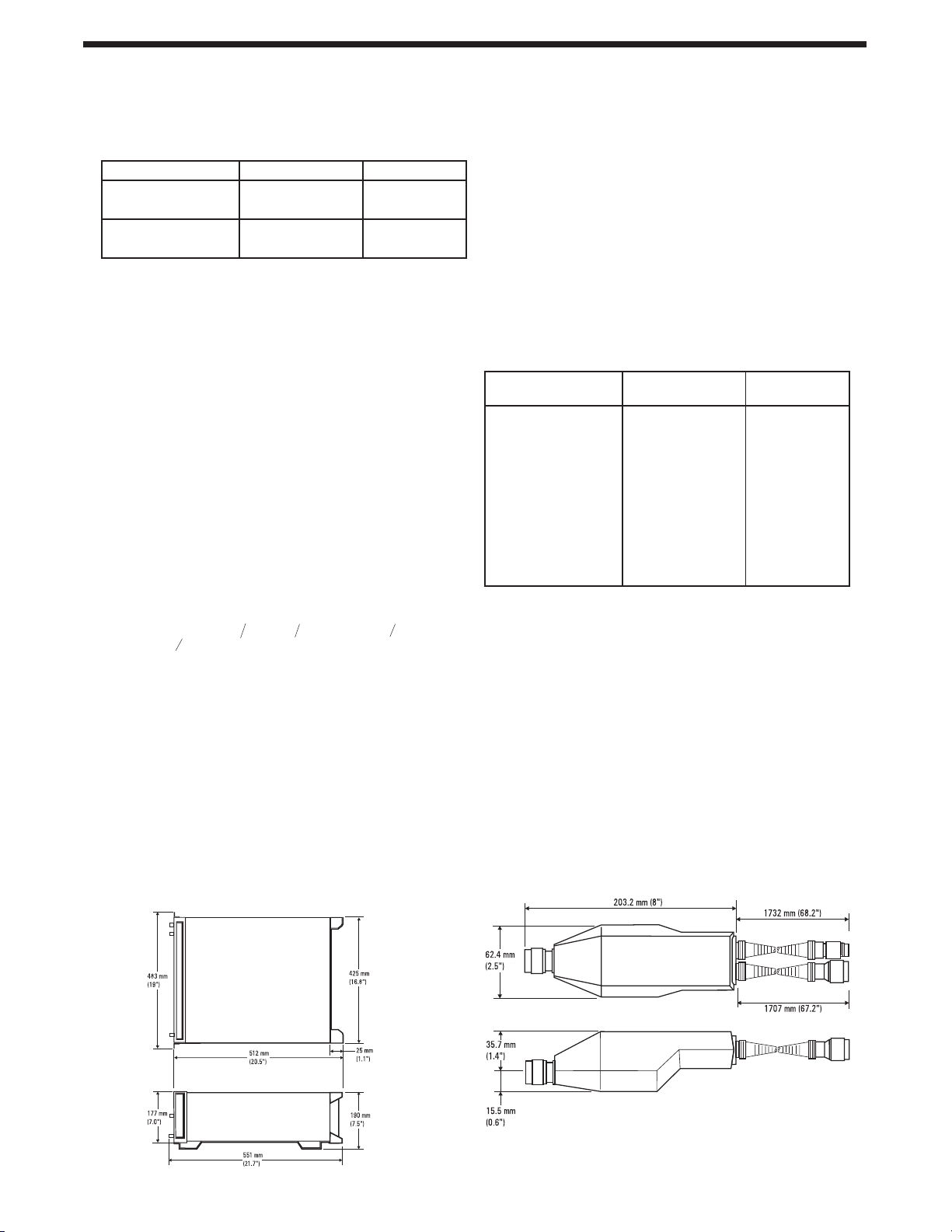
WEIGHT: Net 23.4 kg. (51.5 lb.); Shipping 31.1 kg.
(68.5 1b.).
HP SYSTEM II MODULE SIZE: 7 H X 1 MW X 20 D.
HP SYSTEM II MODULE SIZE: 7 H X 1 MW X 20 D
DIMENSIONS:
SWITCH Isolation: >90 dB.
WEIGHT:
Net 0.8 kg. (1.75 lb.); Shipping 1.2 kg. (2.6 lb.);
Gross without manual 1050g.
DIMENSIONS:
11

HP 8901B Rear Panel Inputs/Outputs
Supplemental Characteristics:
FM OUTPUT:
10 kΩ impedance, – 9V to 6V into an open circuit: ~6V/MHz, dc coupled,
16 kHz bandwidth (one pole).
AM OUTPUT:
RECORDER OUTPUT:
IF OUTPUT:
10 MHz REFERENCE OUTPUT:
10 MHz REFERENCE INPUT
LO INPUT (Option 003): 50
RF SWITCH REMOTE CONTROL OUTPUT:
FREQUENCY OFFSET MODE REMOTE CONTROL OUTPUT:
Ω
impedance, – 4V to OV into an open circuit, ~8 mV/%, dc coupled,
10 k
16 kHz bandwidth(one pole).
Ω
DC voltage proportional to the measured result, 1 k
4V for each resolution range, into an open circuit.
50
Ω
impedance, 150 kHz to 2.5 MHz, – 27 dBm to – 3 dBm.
Ω
impedance, TTL levels (OV to >2.2V into an open circuit), available
50
only with Option OO2 1X10⁻⁹ /day internal reference, outputs internal
reference only.
14
>500Ω impedance, 0.5 V
Provides output signals to remotely control either an HP 33311B
Option 011 or an HP 8761A RF switch.
TTL high output if in frequency offset mode (Special Function 27.1 or
27.3) with an external L.O. frequency >0, TTL low output for all
other cases.
:
peak-to-peak
Ω
minimum input level.
impedance, ~1.27 MHz to 1301.5 MHz, 0 dBm.
impedance, OV to
14 External reference accuracy affects accuracy of all measurements.
Ordering Information
HP 8901B Modulation Analyzer
Option 001: Rear panel instead of front panel connections for input,
modulation output, and calibrators
Option 002: 1X10
Option 003: Rear panel instead of front panel connections which allows
use with an external local oscillator
Option 004: Operation from 48 Hz to 400 Hz power line (Temp. <400C)
Option 021: Add HP 11722A Sensor Module
Option 907: Front panel handle kit
Option 908: Rack mounting flange kit
Option 909: Front panel handle plus rack mounting flange kit
Option 910: Extra manuals
HP 11722A Sensor Module
-9
/day internal reference oscillator
Option 910: Extra manual
12
Data subject to change
© Hewlett-Packard Company 1997
Printed in U.S.A. 5/98
5966-4569E
 Loading...