


Reference Guide
Agilent Technologies
8753ET/ES
Network Analyzers
Part Number 08753-90473
Printed in USA
May 2000
Supersedes August 1999
© Copyright 1999, 2000
Agilent Technologies

Notice
The information contained in this document is subject to change without notice.
Agilent Technologies makes no warranty of any kind with regard to this material,
including but not limited to, the implied warranties of merchantability and fitness for a
particular purpose. Agilent Technologies shall not be liable for errors contained herein or
for incidental or consequential damages in connection with the furnishing, performance,or
use of this material.
ii

Certification
Agilent Technologiescertifies that this product met its published specifications at the time
of shipment from the factory. Agilent Technologies further certifies that its calibration
measurements are traceable to the United States National Institute of Standards and
Technology, to the extent allowed by the Institute's calibration facility, and to the
calibration facilities of other International Standards Organization members.
Regulatory and Warranty Information
The regulatory and warranty information is located in the user’s guide.
Assistance
Product maintenance agreements and other customer assistance agreements are available
for Agilent Technologies products. For any assistance, contact your nearest Agilent
Technologies sales or service office. See the user’s guide for the nearest office.
Safety Notes
The following safety notes are used throughout this manual. Familiarize yourself with
each of the notes and its meaning before operating this instrument. All pertinent safety
notes for using this product are located in the user’s guide.
WARNING Warning denotes a hazard. It calls attention to a procedure which, if
not correctly performed or adhered to, could result in injury or loss
of life. Do not proceed beyond a warning note until the indicated
conditions are fully understood and met.
CAUTION Caution denotes a hazard. It calls attention to a procedure that, if not
correctly performed or adhered to, would result in damage to or destruction of
the instrument. Do not proceed beyond a caution sign until the indicated
conditions are fully understood and met.
iii

How to Use This Guide
SOFTKEY
This guide uses the following conventions:
Front-Panel Key
Screen Text This represents text displayed on the instrument’s screen.
This represents a key physically located on the
instrument.
This represents a “softkey,” a key whose label is
determined by the instrument’s firmware.
iv

Documentation Map
The Installation and Quick Start Guide provides procedures for
installing, configuring, and verifying the operation of the analyzer. It
also will help you familiarize yourself with the basic operation of the
analyzer.
The User’s Guide shows how to make measurements, explains
commonly-used features, and tells you how to get the most
performance from your analyzer.
The Reference Guide provides reference information, such as
specifications, menu maps, and key definitions.
The Programmer’s Guide provides general GPIB programming
information, a command reference, and example programs. The
Programmer’s Guide contains a CD-ROM with example programs.
The CD-ROM provides the Installation and Quick Start Guide, the
User’s Guide, the Reference Guide, and the Programmer’s Guide in
PDF format for viewing or printing from a PC.
The Service Guide provides information on calibrating,
troubleshooting,andservicingyouranalyzer. The Service Guide is not
part of a standard shipment and is available only as Option 0BW, or
by ordering part number 08753-90484. A CD-ROM with the Service
Guide in PDF format is included for viewing or printing from a PC.
v

Contents
1. 8753ES Specifications and Characteristics
Definitions . . . . . . . . . . . . . . . . . . . . . . . . . . . . . . . . . . . . . . . . . . . . . . . . . . . . . . . . . . . . . . . . . 1-2
Corrected System Performance. . . . . . . . . . . . . . . . . . . . . . . . . . . . . . . . . . . . . . . . . . . . . . . . . 1-3
Instrument Specifications. . . . . . . . . . . . . . . . . . . . . . . . . . . . . . . . . . . . . . . . . . . . . . . . . . . . 1-10
Uncorrected Port Performance . . . . . . . . . . . . . . . . . . . . . . . . . . . . . . . . . . . . . . . . . . . . . . 1-10
Test Port Output. . . . . . . . . . . . . . . . . . . . . . . . . . . . . . . . . . . . . . . . . . . . . . . . . . . . . . . . . . 1-12
Test Port Input . . . . . . . . . . . . . . . . . . . . . . . . . . . . . . . . . . . . . . . . . . . . . . . . . . . . . . . . . . . 1-16
General Information. . . . . . . . . . . . . . . . . . . . . . . . . . . . . . . . . . . . . . . . . . . . . . . . . . . . . . . 1-22
Speed Parameters. . . . . . . . . . . . . . . . . . . . . . . . . . . . . . . . . . . . . . . . . . . . . . . . . . . . . . . 1-28
Power Meter Calibration Accuracy . . . . . . . . . . . . . . . . . . . . . . . . . . . . . . . . . . . . . . . . . 1-31
2. 8753ET Specifications and Characteristics
Definitions . . . . . . . . . . . . . . . . . . . . . . . . . . . . . . . . . . . . . . . . . . . . . . . . . . . . . . . . . . . . . . . . . 2-2
Corrected System Performance. . . . . . . . . . . . . . . . . . . . . . . . . . . . . . . . . . . . . . . . . . . . . . . . . 2-3
Instrument Specifications. . . . . . . . . . . . . . . . . . . . . . . . . . . . . . . . . . . . . . . . . . . . . . . . . . . . . 2-6
Uncorrected Port Performance . . . . . . . . . . . . . . . . . . . . . . . . . . . . . . . . . . . . . . . . . . . . . . . 2-6
Test Port Output. . . . . . . . . . . . . . . . . . . . . . . . . . . . . . . . . . . . . . . . . . . . . . . . . . . . . . . . . . . 2-7
Test Port Input . . . . . . . . . . . . . . . . . . . . . . . . . . . . . . . . . . . . . . . . . . . . . . . . . . . . . . . . . . . 2-11
General Information. . . . . . . . . . . . . . . . . . . . . . . . . . . . . . . . . . . . . . . . . . . . . . . . . . . . . . . 2-18
Speed Parameters. . . . . . . . . . . . . . . . . . . . . . . . . . . . . . . . . . . . . . . . . . . . . . . . . . . . . . . 2-24
3. Front/Rear Panel
Front Panel Features . . . . . . . . . . . . . . . . . . . . . . . . . . . . . . . . . . . . . . . . . . . . . . . . . . . . . . . . 3-2
Analyzer Display . . . . . . . . . . . . . . . . . . . . . . . . . . . . . . . . . . . . . . . . . . . . . . . . . . . . . . . . . . . 3-5
Rear Panel Features and Connectors . . . . . . . . . . . . . . . . . . . . . . . . . . . . . . . . . . . . . . . . . .3-10
4. Menu Maps
Menu Maps . . . . . . . . . . . . . . . . . . . . . . . . . . . . . . . . . . . . . . . . . . . . . . . . . . . . . . . . . . . . . . . . 4-2
5. Hardkey/Softkey Reference
Key Reference . . . . . . . . . . . . . . . . . . . . . . . . . . . . . . . . . . . . . . . . . . . . . . . . . . . . . . . . . . . . . . 5-2
Where to Look for More Information . . . . . . . . . . . . . . . . . . . . . . . . . . . . . . . . . . . . . . . . . . . . 5-3
Guide Terms and Conventions . . . . . . . . . . . . . . . . . . . . . . . . . . . . . . . . . . . . . . . . . . . . . . . . . 5-3
Analyzer Functions . . . . . . . . . . . . . . . . . . . . . . . . . . . . . . . . . . . . . . . . . . . . . . . . . . . . . . . . . . 5-4
6. Error Messages
Error Messages . . . . . . . . . . . . . . . . . . . . . . . . . . . . . . . . . . . . . . . . . . . . . . . . . . . . . . . . . . . . . 6-2
Error Messages in Alphabetical Order . . . . . . . . . . . . . . . . . . . . . . . . . . . . . . . . . . . . . . . . . . 6-3
Error Messages in Numerical Order . . . . . . . . . . . . . . . . . . . . . . . . . . . . . . . . . . . . . . . . . . . 6-23
7. Options and Accessories
Using This Chapter. . . . . . . . . . . . . . . . . . . . . . . . . . . . . . . . . . . . . . . . . . . . . . . . . . . . . . . . . . 7-2
Analyzer Options Available . . . . . . . . . . . . . . . . . . . . . . . . . . . . . . . . . . . . . . . . . . . . . . . . . . . 7-3
Option 1D5, High Stability Frequency Reference . . . . . . . . . . . . . . . . . . . . . . . . . . . . . . . . 7-3
Option 002, Harmonic Mode . . . . . . . . . . . . . . . . . . . . . . . . . . . . . . . . . . . . . . . . . . . . . . . . .7-3
Option 004, Source Attenuator (ET Only) . . . . . . . . . . . . . . . . . . . . . . . . . . . . . . . . . . . . . . 7-3
Option 006, 6 GHz Operation . . . . . . . . . . . . . . . . . . . . . . . . . . . . . . . . . . . . . . . . . . . . . . . . 7-3
Option 010, Time Domain . . . . . . . . . . . . . . . . . . . . . . . . . . . . . . . . . . . . . . . . . . . . . . . . . . . 7-3
Option 011, Delete Built-In Test Set (ES Only) . . . . . . . . . . . . . . . . . . . . . . . . . . . . . . . . . . 7-3
Option 014, Configurable Test Set (ES Only). . . . . . . . . . . . . . . . . . . . . . . . . . . . . . . . . . . . 7-3
Option 075, 75 W Impedance (ES Only) . . . . . . . . . . . . . . . . . . . . . . . . . . . . . . . . . . . . . . . . 7-4
Option 1CM, Rack Mount Flange Kit Without Handles . . . . . . . . . . . . . . . . . . . . . . . . . . . 7-4
Contents-vii

Contents
Option 1CP, Rack Mount Flange Kit With Handles . . . . . . . . . . . . . . . . . . . . . . . . . . . . . . 7-4
Service and Support Options . . . . . . . . . . . . . . . . . . . . . . . . . . . . . . . . . . . . . . . . . . . . . . . .7-4
Accessories Available . . . . . . . . . . . . . . . . . . . . . . . . . . . . . . . . . . . . . . . . . . . . . . . . . . . . . . . . 7-5
Measurement Accessories . . . . . . . . . . . . . . . . . . . . . . . . . . . . . . . . . . . . . . . . . . . . . . . . . . . 7-5
Test-Port Cables: 7-mm . . . . . . . . . . . . . . . . . . . . . . . . . . . . . . . . . . . . . . . . . . . . . . . . . . . 7-5
Test-Port Cables: Type-N . . . . . . . . . . . . . . . . . . . . . . . . . . . . . . . . . . . . . . . . . . . . . . . . . . 7-5
Calibration Kits . . . . . . . . . . . . . . . . . . . . . . . . . . . . . . . . . . . . . . . . . . . . . . . . . . . . . . . . . 7-5
RF electronic calibration modules and PC software. . . . . . . . . . . . . . . . . . . . . . . . . . . . . 7-6
Verification Kit . . . . . . . . . . . . . . . . . . . . . . . . . . . . . . . . . . . . . . . . . . . . . . . . . . . . . . . . . . 7-7
Minimum Loss Pads and Adapters . . . . . . . . . . . . . . . . . . . . . . . . . . . . . . . . . . . . . . . . . . . .7-8
Test Configuration Accessories . . . . . . . . . . . . . . . . . . . . . . . . . . . . . . . . . . . . . . . . . . . . . . . 7-8
RF Limiter. . . . . . . . . . . . . . . . . . . . . . . . . . . . . . . . . . . . . . . . . . . . . . . . . . . . . . . . . . . . . . 7-8
Probe . . . . . . . . . . . . . . . . . . . . . . . . . . . . . . . . . . . . . . . . . . . . . . . . . . . . . . . . . . . . . . . . . .7-8
Amplifier . . . . . . . . . . . . . . . . . . . . . . . . . . . . . . . . . . . . . . . . . . . . . . . . . . . . . . . . . . . . . . . 7-9
Power Meters . . . . . . . . . . . . . . . . . . . . . . . . . . . . . . . . . . . . . . . . . . . . . . . . . . . . . . . . . . . 7-9
Power Sensors. . . . . . . . . . . . . . . . . . . . . . . . . . . . . . . . . . . . . . . . . . . . . . . . . . . . . . . . . . . 7-9
Keyboard Template . . . . . . . . . . . . . . . . . . . . . . . . . . . . . . . . . . . . . . . . . . . . . . . . . . . . . . . 7-10
8. Preset State and Memory Allocation
Preset State . . . . . . . . . . . . . . . . . . . . . . . . . . . . . . . . . . . . . . . . . . . . . . . . . . . . . . . . . . . . . . . . 8-2
Memory Allocation. . . . . . . . . . . . . . . . . . . . . . . . . . . . . . . . . . . . . . . . . . . . . . . . . . . . . . . . . . 8-12
Types of Memory and Data Storage . . . . . . . . . . . . . . . . . . . . . . . . . . . . . . . . . . . . . . . . . .8-12
Volatile Memory . . . . . . . . . . . . . . . . . . . . . . . . . . . . . . . . . . . . . . . . . . . . . . . . . . . . . . . .8-12
Non-Volatile Memory . . . . . . . . . . . . . . . . . . . . . . . . . . . . . . . . . . . . . . . . . . . . . . . . . . . . 8-12
Determining Memory Requirements. . . . . . . . . . . . . . . . . . . . . . . . . . . . . . . . . . . . . . . . . . 8-14
Storing Data to Disk . . . . . . . . . . . . . . . . . . . . . . . . . . . . . . . . . . . . . . . . . . . . . . . . . . . . . . 8-16
Conserving Memory . . . . . . . . . . . . . . . . . . . . . . . . . . . . . . . . . . . . . . . . . . . . . . . . . . . . . . 8-18
Using Saved Calibration Sets . . . . . . . . . . . . . . . . . . . . . . . . . . . . . . . . . . . . . . . . . . . . . . . 8-18
9. Understanding the CITIfile Data
Format
Using This Chapter. . . . . . . . . . . . . . . . . . . . . . . . . . . . . . . . . . . . . . . . . . . . . . . . . . . . . . . . . . 9-2
The CITIfile Data Format. . . . . . . . . . . . . . . . . . . . . . . . . . . . . . . . . . . . . . . . . . . . . . . . . . . . .9-3
Description and Overview . . . . . . . . . . . . . . . . . . . . . . . . . . . . . . . . . . . . . . . . . . . . . . . . . . . 9-3
Data Formats . . . . . . . . . . . . . . . . . . . . . . . . . . . . . . . . . . . . . . . . . . . . . . . . . . . . . . . . . . . 9-3
File and Operating System Formats . . . . . . . . . . . . . . . . . . . . . . . . . . . . . . . . . . . . . . . . .9-3
Definition of CITIfile Terms. . . . . . . . . . . . . . . . . . . . . . . . . . . . . . . . . . . . . . . . . . . . . . . . . . 9-3
A CITIfile Package . . . . . . . . . . . . . . . . . . . . . . . . . . . . . . . . . . . . . . . . . . . . . . . . . . . . . . . 9-4
The CITIfile Header . . . . . . . . . . . . . . . . . . . . . . . . . . . . . . . . . . . . . . . . . . . . . . . . . . . . . . 9-4
An Array of Data. . . . . . . . . . . . . . . . . . . . . . . . . . . . . . . . . . . . . . . . . . . . . . . . . . . . . . . . . 9-5
CITIfile Keyword . . . . . . . . . . . . . . . . . . . . . . . . . . . . . . . . . . . . . . . . . . . . . . . . . . . . . . . . 9-5
CITIfile Examples . . . . . . . . . . . . . . . . . . . . . . . . . . . . . . . . . . . . . . . . . . . . . . . . . . . . . . . . . 9-5
Example 2, An 8510 Display Memory File . . . . . . . . . . . . . . . . . . . . . . . . . . . . . . . . . . . . 9-5
Example 3, 8510 Data file . . . . . . . . . . . . . . . . . . . . . . . . . . . . . . . . . . . . . . . . . . . . . . . . . 9-6
Example 4, 8510 3-Term Frequency List Cal Set File . . . . . . . . . . . . . . . . . . . . . . . . . . .9-6
CITIfile Keywords . . . . . . . . . . . . . . . . . . . . . . . . . . . . . . . . . . . . . . . . . . . . . . . . . . . . . . . . . . . 9-8
Useful Calculations . . . . . . . . . . . . . . . . . . . . . . . . . . . . . . . . . . . . . . . . . . . . . . . . . . . . . . . . . 9-11
Computing Frequency Points . . . . . . . . . . . . . . . . . . . . . . . . . . . . . . . . . . . . . . . . . . . . . . . 9-11
Expressing CITIfile Data in Other Data Formats . . . . . . . . . . . . . . . . . . . . . . . . . . . . . . . 9-12
Example Data . . . . . . . . . . . . . . . . . . . . . . . . . . . . . . . . . . . . . . . . . . . . . . . . . . . . . . . . . . 9-13
Contents-viii

Contents
10. Determining System Measurement Uncertainties
Introduction . . . . . . . . . . . . . . . . . . . . . . . . . . . . . . . . . . . . . . . . . . . . . . . . . . . . . . . . . . . . . . .10-2
Sources of Measurement Errors . . . . . . . . . . . . . . . . . . . . . . . . . . . . . . . . . . . . . . . . . . . . . . .10-3
Sources of Systematic Errors . . . . . . . . . . . . . . . . . . . . . . . . . . . . . . . . . . . . . . . . . . . . . . . .10-3
Sources of Random Errors . . . . . . . . . . . . . . . . . . . . . . . . . . . . . . . . . . . . . . . . . . . . . . . . . .10-4
Determining Expected System Performance . . . . . . . . . . . . . . . . . . . . . . . . . . . . . . . . . . . . .10-5
Determining Cable Stability Terms (CR1, CR2, C
Measurement Uncertainty Equations. . . . . . . . . . . . . . . . . . . . . . . . . . . . . . . . . . . . . . . . . . .10-8
Forward Reflection Uncertainty. . . . . . . . . . . . . . . . . . . . . . . . . . . . . . . . . . . . . . . . . . . . . .10-8
Forward Transmission Uncertainty. . . . . . . . . . . . . . . . . . . . . . . . . . . . . . . . . . . . . . . . . . .10-9
Reverse Reflection Uncertainty . . . . . . . . . . . . . . . . . . . . . . . . . . . . . . . . . . . . . . . . . . . . .10-10
Reverse Transmission Uncertainty . . . . . . . . . . . . . . . . . . . . . . . . . . . . . . . . . . . . . . . . . .10-11
TM1
, C
TM2
, C
TP1
, C
). . . . . . . . . . . . . . .10-6
TP2
Contents-ix

1 8753ES
Specifications and Characteristics
1-1

8753ES Specifications and Characteristics
Definitions
Definitions
All specifications and characteristics apply over a 25 °C ±5 °C range (unless otherwise
stated) and 1/2 hour after the instrument has been turned on.
Specification (spec.): Warranted performance. Specifications include guardbands to
account for the expected statistical performance distribution, measurement uncertainties,
and changes in performance due to environmental conditions.
Characteristic (char.): A performance parameter that the product is expected to meet
before it leaves the factory, but that is not verified in the field and is not covered by the
product warranty. A characteristic includes the same guardbands as a specification.
Typical (typ.): Expected performance of an average unit which does not include
guardbands. It is not covered by the product warranty.
Nominal (nom.): A general, descriptive term that does not imply a level of performance. It
is not covered by the product warranty.
Calibration: The process of measuring known standards from a calibration kit to
characterize a network analyzer’s systematic (repeatable) errors.
Corrected (residual) Performance: Indicates performance after error correction
(calibration). It is determined by the quality of calibration standards and how well
“known” they are, plus system repeatability, stability, and noise.
Uncorrected (raw) Performance: Indicates instrument performance without error
correction. The uncorrected performance affects the stability of a calibration.
Standard: When referring to the analyzer, this includes all options unless noted otherwise.
1-2

8753ES Specifications and Characteristics
Corrected System Performance
Corrected System Performance
The specifications in this section apply for measurements made using 10 Hz IF bandwidth,
no averaging, and at an environmental temperature of 25 ±5 °C, with less than 1 °C
deviation from the calibration temperature. Assumes that an isolation calibration was
performed with an averaging factor of 16.
Table 1-1 System Dynamic Range, All Device Connector Types
8753ES, All Options, All Cal Kits, All Cables, 10 Hz IF BW
Description Specification Supplemental
Information
System Transmission Dynamic Range
Standard (50 Ω)
30 kHz to 50 kHz 70 dB
50 kHz to 300 kHz 90 dB
300 kHz to 16 MHz 100 dB
16 MHz to 1.3 GHz 110 dB
1.3 GHz to 3 GHz 110 dB
3 GHz to 6 GHz 105 dB
Option 075 (75 Ω)
30 kHz to 50 kHz 68 dB
50 kHz to 300 kHz 90 dB
300 kHz to 16 MHz 96 dB
16 MHz to 1.3 GHz 106 dB
1.3 GHz to 3 GHz 106 dB
Option 014
30 kHz to 50 kHz 68 dB
50 kHz to 300 kHz 90 dB
300 kHz to 16 MHz 98 dB
16 MHz to 1.3 GHz 108 dB
1.3 GHz to 3 GHz 108 dB
3 GHz to 6 GHz 103 dB
a
a. The System Transmission Dynamic Range is calculated as the difference
between the receiver noise floor and the lesser of either: the source maximum
output or the receiver maximum input.
1-3

8753ES Specifications and Characteristics
Corrected System Performance
Table 1-2 7-mm Device Connector Type
Network Analyzer: 8753ES, Standard and Option 006
Calibration Kit: 85031B (7-mm, 50 Ω)
Cables: 11857D
Calibration: Full 2-Port
IF BW = 10 Hz, Avg off, Temp = 25 ± 5 °C with < 1 °C deviation from cal temp, Isol cal with avg = 8
Typical Specification
Description
Directivity 55 dB 55 dB 51 dB 46 dB
Source Match 55 dB 51 dB 49 dB 43 dB
Load Match 55 dB 55 dB 51 dB 46 dB
Refl. Tracking
Magnitude (db) ±(0.001 + .02/°C) ±(0.001 + .01/°C) ±(0.005 + .02/°C) ±(0.020 + .03/°C)
Phase (deg) ±(0.007 + .05/°C) ±(0.007 + .05/°C) ±(0.033 + .05/°C) ±(0.132 + 0.2/°C)
Trans. Tracking
Magnitude (db) ±(0.009 + .02/°C) ±(0.006 + .01/°C) ±(0.009 + .02/°C) ±(0.021 + .03/°C)
Phase (deg) ±(0.060 + .05/°C) ±(0.040 + .05/°C) ±(0.059 + .05/°C) ±(0.139 + 0.2/°C)
30 to 300 kHz 300 kHz to
1.3 GHz
1.3 to 3 GHz 3 to 6 GHz
(Opt 006 only)
Transmission Uncertainty (Specification)
Reflection Uncertainty (Specification)
1-4

8753ES Specifications and Characteristics
Corrected System Performance
Table 1-3 Type-N (50 Ω) Device Connector Type
Network Analyzer: 8753ES, Standard and Option 006
Calibration Kit: 85032B/E (Type-N, 50 Ω)
Cables: 11857D
Calibration: Full 2-Port
IF BW = 10 Hz, Avg off, Temp = 25 ± 5 °C with < 1 °C deviation from cal temp, Isol cal with avg = 8
Typical Specification
Description
Directivity 50 dB 50 dB 47 dB 40 dB
Source Match 49 dB 42 dB 36 dB 31 dB
Load Match 50 dB 50 dB 47 dB 40 dB
Refl. Tracking
Magnitude (db) ±(0.005 + .02/°C) ±(0.009 + .01/°C) ±(0.019 + .02/°C) ±(0.070 + .03/°C)
Phase (deg) ±(0.033 + .05/°C) ±(0.059 + .05/°C) ±(0.125 + .05/°C) ±(0.462 + 0.2/°C)
Trans. Tracking
Magnitude (db) ±(0.017 + .02/°C) ±(0.013 + .01/°C) ±(0.026 + .02/°C) ±(0.065 + .04/°C)
Phase (deg) ±(0.113 + .05/°C) ±(0.277 + .05/°C) ±(0.172 + .05/°C) ±(0.429 + 0.2/°C)
30 to 300 kHz 300 kHz to
1.3 GHz
1.3 to 3 GHz 3 to 6 GHz
(Opt 006 only)
Transmission Uncertainty (Specification)
Reflection Uncertainty (Specification)
1-5

8753ES Specifications and Characteristics
Corrected System Performance
Table 1-4 3.5-mm Device Connector Type
Network Analyzer: 8753ES, Standard and Option 006
Calibration Kit: 85033D (3.5-mm, 50 Ω)
Cables: 11857D
Calibration: Full 2-Port
IF BW = 10 Hz, Avg off, Temp = 25 ± 5°C with < 1°C deviation from cal temp, Isol cal with avg = 8
Typical Specification
Description
Directivity 49 dB 46 dB 44 dB 38 dB
Source Match 49 dB 44 dB 41 dB 37 dB
Load Match 49 dB 46 dB 44 dB 38 dB
Refl. Tracking
Magnitude (db) ±(0.001 + .02/°C) ±(0.005 + .01/°C) ±(0.007 + .02/°C) ±(0.009 + .03/°C)
Phase (deg) ±(0.007 + .05/°C) ±(0.033 + .05/°C) ±(0.046 + .05/°C) ±(0.059 + 0.2/°C)
Trans. Tracking
Magnitude (db) ±(0.019 + .02/°C) ±(0.014 + .01/°C) ±(0.022 + .02/°C) ±(0.048 + .03/°C)
Phase (deg) ±(0.124 + .05/°C) ±(0.092 + .05/°C) ±(0.145 + .05/°C) ±(0.317 + 0.2/°C)
30 to 300 kHz 300 kHz to
1.3 GHz
1.3 to 3 GHz 3 to 6 GHz
(Opt 006 only)
Transmission Uncertainty (Specification)
Reflection Uncertainty (Specification)
1-6

8753ES Specifications and Characteristics
Corrected System Performance
Table 1-5 7/16-mm Device Connector Type
Network Analyzer: 8753ES, Standard and Option 006
Calibration Kit: 85038A (7/16-mm, 50 Ω)
Cables: 11857D
Calibration: Full 2-Port
IF BW = 10 Hz, Avg off, Temp = 25 ± 5°C with < 1°C deviation from cal temp, Isol cal with avg = 8
Typical Specification
Description
Directivity 40 dB 40 dB 40 dB 36 dB
Source Match 37 dB 37 dB 37 dB 34 dB
Load Match 40 dB 40 dB 40 dB 36 dB
Refl. Tracking
Magnitude (db) ±(0.089 + .02/°C) ±(0.089 + .01/°C) ±(0.089 + .02/°C) ±(0.115 + .03/°C)
Phase (deg) ±(0.587 + .05/°C) ±(0.587 + .05/°C) ±(0.587 + .05/°C) ±(0.759 + 0.2/°C)
Trans. Tracking
Magnitude (db) ±(0.066 + .02/°C) ±(0.029 + .01/°C) ±(0.033 + .02/°C) ±(0.062 + .03/°C)
Phase (deg) ±(0.436 + .05/°C) ±(0.192 + .05/°C) ±(0.219 + .05/°C) ±(0.436 + 0.2/°C)
30 to 300 kHz 300 kHz to
1.3 GHz
1.3 to 3 GHz 3 to 6 GHz
(Opt 006 only)
Transmission Uncertainty (Specification)
Reflection Uncertainty (Specification)
1-7

8753ES Specifications and Characteristics
Corrected System Performance
Table 1-6 Type-N (75Ω) Device Connector Type
Network Analyzer: 8753ES, Option 075
Calibration Kit: 85036B/E (Type-N, 75Ω)
Cables: 11857B
Calibration: Full 2-Port
IF BW = 10 Hz, Avg off, Temp = 25 ± 5°C with < 1°C deviation from cal temp, Isol cal with avg = 8
Typical Specification
Description
Directivity 48 dB 48 dB 43 dB N/A
Source Match 47 dB 41 dB 35 dB N/A
Load Match 48 dB 48 dB 43 dB N/A
Refl. Tracking
Magnitude (db) ±(0.004 + .02/°C) ±(0.010 + .01/°C) ±(0.019 + .02/°C) N/A
Phase (deg) ±(0.026 + .05/°C) ±(0.066 + .05/°C) ±(0.125 + .05/°C) N/A
Trans. Tracking
Magnitude (db) ±(0.022 + .02/°C) ±(0.016 + .01/°C) ±(0.033 + .02/°C) N/A
Phase (deg) ±(0.143 + .05/°C) ±(0.106 + .05/°C) ±(0.218 + .05/°C) N/A
30 to 300 kHz 300 kHz to
1.3 GHz
1.3 to 3 GHz 3 to 6 GHz
(Opt 006 only)
Transmission Uncertainty (Specification)
Reflection Uncertainty (Specification)
1-8

8753ES Specifications and Characteristics
Corrected System Performance
Table 1-7 Type-F (75 Ω) Device Connector Type
Network Analyzer: 8753ES, Option 075
Calibration Kit: 85039B (Type-F, 75 Ω)
Cables: 11857B
Calibration: Full 2-Port
IF BW = 10 Hz, Avg off, Temp = 25 ± 5°C with < 1°C deviation from cal temp, Isol cal with avg = 8
Typical Specification
Description
Directivity 45 dB 45 dB 40 dB N/A
Source Match 40 dB 40 dB 30 dB N/A
Load Match 45 dB 45 dB 40 dB N/A
Refl. Tracking
Magnitude (db) ±(0.043 + .02/°C) ±(0.060 + .01/°C) ±(0.0240 +.02/°C) N/A
Phase (deg) ±(0.396 + .05/°C) ±(0.396 + .05/°C) ±(0.158 + .05/°C) N/A
Trans. Tracking
Magnitude (db) ±(0.033 + .02/°C) ±(0.019 + .01/°C) ±(0.057 +.02/°C) N/A
Phase (deg) ±(0.283 + .05/°C) ±(0.125 + .05/°C) ±(0.376 + .05/°C) N/A
30 to 300 kHz 300 kHz to
1.3 GHz
1.3 to 3 GHz 3 to 6 GHz
(Opt 006 only)
Transmission Uncertainty (Specification)
Reflection Uncertainty (Specification)
1-9

8753ES Specifications and Characteristics
Instrument Specifications
Instrument Specifications
Uncorrected Port Performance
Table 1-8 7-mm Device Connector Type
8753ES (7-mm, 50 Ω), Standard and Option 006
Specification
Description
Directivitya (dB)
Source Matcha (dB)
Load Matcha (dB)
Reflection
Trackinga (dB)
Transmission
Trackinga (dB)
Tracking Stability
(Ratio Measurement)
Magnitude (dB) .002/°C, typ. .002/°C,typ. .002/°C, typ. .002/°C, typ. 0.04/°C, typ.
Phase (deg) .004/°C, typ. .004/°C, typ. .004/°C, typ. .004/°C, typ. 0.20/°C, typ.
Crosstalkb (dB)
a. Does not include the effect of the cable set on the test ports.
b. Measurement conditions: Normalized to a thru, measured with two shorts, 10 Hz IF
bandwidth, averaging factor of 8, alternate mode, source power set to the lesser of the
maximum power out or the maximum receiver power.
30 kHz to
50 kHz
15, typ. 20, typ. 35 30 25
10, typ. 18, typ. 16 16 14
10, typ. 18, typ. 18 16 14
±2.5, typ. ±2.5, typ. ±1.0 ±1.0 ±1.5
±2.5, typ. ±2.5, typ. ±1.0 ±1.0 ±1.5
60, typ. 90, typ. 100 100 90
50 kHz to
300 kHz
300 kHz to
1.3 GHz
1.3 GHz to
3 GHz
3 to 6 GHz
(Opt 006
only)
1-10

8753ES Specifications and Characteristics
Table 1-9 Type-N (75 Ω) Device Connector Type
8753ES (Type-N, 75Ω), Option 075
Description Specification
Instrument Specifications
30 kHz to
50 kHz
Directivitya (dB)
Source Matcha (dB)
Load Matcha (dB)
Reflection
Trackinga (dB)
Transmission
Trackinga (dB)
Tracking Stability
(Ratio Measurement)
Magnitude (dB) .002/°C, typ. .002/°C, typ. .002/°C, typ. .002/°C, typ. 0.04/°C, typ.
Phase (deg) .004/°C, typ. .004/°C, typ. .004/°C, typ. .004/°C, typ. 0.20 °/°C, typ.
Crosstalkb (dB)
a. Does not include the effect of the cable set on the test ports.
b. Measurement conditions: Normalized to a thru, measured with two shorts, 10 Hz IF
bandwidth, averaging factor of 8, alternate mode, source power set to the lesser of the
maximum power out or the maximum receiver power.
15, typ. 20, typ. 35 30 N/A
10, typ. 18, typ. 16 16 N/A
10, typ. 18, typ. 18 16 N/A
±2.5, typ. ±2.5, typ. ±1.0 ±1.0
±2.5, typ. ±2.5, typ. ±1.0 ±1.0
60, typ. 90, typ. 100 100 N/A
50 kHz to
300 kHz
300 kHz to
1.3 GHz
1.3 GHz to
3 GHz
3 to 6 GHz
(Opt 006 only)
N/A
N/A
1-11

8753ES Specifications and Characteristics
Instrument Specifications
Test Port Output
Table 1-10 Test Port Output
8753ES Test Port Output
Description Specification Supplemental Information
Frequency
Range
Standard 30 kHz to 3.0 GHz 10 kHz to 3 GHz, typ.
Option 006 30 kHz to 6.0 GHz 10 kHz to 6 GHz, typ.
Resolution 1 Hz
Stability
Standard ±7.5 ppm, 0˚ to 55˚C, typ.
±3 ppm/year, typ.
Option 1D5 0.05 ppm, 0˚ to 55˚C, typ.
±0.5 ppm/year, typ.
CW Accuracy ±10 ppm at 25˚C ±5˚C
Output Powera (above 300 kHz)
Level Accuracy
b
Standard ±1.0 dB at 0 dBm output level
Option 075 ±1.0 dB at 0 dBm output level
Maximum Leveled Power
c
Standard +10 dBm, char.
Option 075 +8 dBm, char.
Option 014 +8 dBm, char.
Power Range
d
Standard −85 to +10 dBm
Option 075 −85 to +8 dBm
Option 014 −85 to +8 dBm
Power Sweep Range
Standard 25 dB 33 dB, typ.
Option 075 23 dB 31 dB, typ.
Option 014 23 dB 31 dB, typ.
a. Source output performance on port 1 only. Port 2 output performance is a characteristic.
b. Absolute power accuracy at a given power level. Includes absolute accuracy and relative
flatness across frequency.
c. At any given frequency, the achievable power while remaining leveled. Applies to CW
mode only.
d. Power to which the source can be set and phase lock is assured.
1-12

8753ES Specifications and Characteristics
Instrument Specifications
Table 1-11 Test Port Output
8753ES Test Port Output
Description Specification Supplemental Information
Output Powera (above 300 kHz)
Power Resolution 0.01 dB
Attenuator Switch Points:
a. Source output performance on port 1 only. Port 2 output performance is a characteristic.
1-13

8753ES Specifications and Characteristics
Instrument Specifications
Table 1-12 Test Port Output
8753ES Test Port Output
Description Specification Supplemental Information
Output Powera (above 300 kHz)
Linearity
Standard
Option 014/Option 075
Impedance
Standard 50 Ω, nom.
Option 075 75 Ω, nom.
Return Loss
Standard
300 kHz to 3 GHz > 16 dB, typ.
3 GHz to 6 GHz > 14 dB, typ.
Option 075
300 kHz to 3 GHz > 16 dB, typ.
Attenuator Accuracy
0 dB reference; at 50 MHz
10 dB ± 0.2 dB, char. ± 0.5 dB, char.
20 dB ± 0.4 dB, char. ± 0.7 dB, char.
30 dB ± 0.5 dB, char. ± 0.9 dB, char.
40 dB ± 0.7 dB, char. ± 1.2 dB, char.
50 dB ± 0.8 dB, char. ± 1.5 dB, char.
60 dB ± 1.0 dB, char. ± 1.8dB, char.
70 dB ± 1.2 dB, char. ± 2.1 dB, char.
b
−15 to +5 dBm ±0.2 dB relative to 0 dBm output level
+5 to +10 dBm ±0.5 dB relative to 0 dBm output level
−15 to +5 dBm ±0.2 dB relative to 0 dBm output level
+5 to +8 dBm ±0.5 dB relative to 0 dBm output level
c
300 kHz to 3 GHz 3 GHz to 6 GHz
a. Source output performance on port 1 only. Port 2 output performance is a characteristic.
b. Change in source output power for a given change in source power setting at any given
frequency.
c. The accuracy, relative to the 0 dB setting, of each setting of an attenuator, at a given
frequency.
1-14

8753ES Specifications and Characteristics
Instrument Specifications
Table 1-13 Test Port Output
8753ES Test Port Output
Description Specification Supplemental Information
Signal Purity
2nd Harmonic 16 MHz to 1.5 GHz
at maximum output power < −25 dBc (Option 002 only) < −25 dBc, char.
at 10 dB below maximum
output power
at 20 dB below maximum
output power
3rd Harmonic 16 MHz to 1 GHz
at maximum output power < −25 dBc (Option 002 only) < −25 dBc, char.
at 10 dB below maximum
output power
at 20 dB below maximum
output power
Non-harmonic Spurious
Mixer Related
at maximum output power < −30 dBc, typ.
at 20 dB below maximum
output power
a
(source freq.)
16 MHz to 3 GHz
(Option 006, source freq.)
(non-Option 002)
< −40 dBc, typ.
< −50 dBc, typ.
(source freq.)
16 MHz to 2 GHz
(Option 006, source freq.)
(non-Option 002)
< −40 dBc, typ.
< −50 dBc, typ.
< −55 dBc, typ.
a. Source output performance on port 1 only. Port 2 output performance is a characteristic.
1-15

8753ES Specifications and Characteristics
Instrument Specifications
Test Port Input
Table 1-14 Test Port Input
8753ES Test Port Input
Description Specification Supplemental Information
Frequency Range
Standard 30 kHz to 3.0 GHz 10 kHz to 3 GHz, typ.
Option 006 30 kHz to 6.0 GHz 10 kHz to 6 GHz, typ.
Frequency Response, Non-Ratio Measurement (A or B)
300 kHz to 3 GHz ±1 dB at preset power level
3 GHz to 6 GHz ±2 dB at preset power level
Impedance
Standard 50 Ω, nominal.
Return Loss
Standard See uncorrected load match
chart
Maximum Input Level
Standard +10 dBm
Compression See dynamic accuracy chart
Damage Level
Standard > +26 dBm or > 35 Vdc, typ.
Noise Floor
8753ES
300 kHz to 3 GHz
3 kHz IF Bandwidth ≤−82 dBm
10 Hz IF Bandwidth ≤−102 dBm ≤−110 dBm, typ.
3 GHz to 6 GHz
3 kHz IF Bandwidth ≤−77 dBm
10 Hz IF Bandwidth ≤−97 dBm ≤−105 dBm, typ.
8753ES Option 075
300 kHz to 3 GHz
3 kHz IF Bandwidth ≤−80 dBm
10 Hz IF Bandwidth ≤−100 dBm ≤−110 dBm, typ.
a
a. RMS value of a linear magnitude trace expressed in dBm, with the source power set to
minimum to minimize the effects of crosstalk.
1-16

8753ES Specifications and Characteristics
Instrument Specifications
Table 1-15 Test Port Input
8753ES Test Port Input
Description Specification Supplemental Information
Internally Generated Harmonics (Option 002 Only)
2nd Harmonic 16 MHz to 3 GHz
at +8 dBm input level < −15 dBc
at +0 dBm input level < −30 dBc, typ.
at −15 dBm input level < −45 dBc, typ.
3rd Harmonic 16 MHz to 2 GHz
at +8 dBm input level < −30 dBc
at +0 dBm input level < −50 dBc, typ.
at −15 dBm input level < −50 dBc, typ.
Harmonic Measurement Accuracy
16 MHz to 3 GHz ±1.5 dB
3 GHz to 6 GHz ±3 dB
Harmonic Measurement Dynamic Range
Standard −40 dBc, typ.
output at −10 dBm and input
at < −15 dBm
Frequency Offset Operation
Frequency Range
Standard 300 kHz to 3 GHz
Option 006 300 kHz to 6 GHz
R Channel Input Requirements
300 kHz to 3 GHz 0 to −35 dBm
3 GHz to 6 GHz 0 to −30 dBm
LO Spectral Purity and
Accuracy
Maximum Spurious Input < −25 dBc, typ.
Residual FM < 20 kHz, typ.
Frequency Accuracy −1 to +1 MHz of nominal
a
frequency, typ.
a. The RF source characteristics in this mode are dependent on the stability of the external
LO source. The RF source tracks the LO to maintain a stable IF signal at the R channel
receiver input.
1-17

8753ES Specifications and Characteristics
Instrument Specifications
Table 1-16 Test Port Input
8753ES Test Port Input
Description Specification Supplemental Information
External Source Mode
Frequency Range at −25 dBm R channel power
Standard 300 kHz to 3 GHz
Option 006 300 kHz to 6 GHz
R Input Requirements
Power Level 0 to −25 dBm, typ.
R Input Spectral Purity
Requirement
Maximum Spurious Input < −30 dBc, typ.
Residual FM < 20 kHz, typ.
Settling Time
Auto 500 ms, typ.
Manual 50 ms, typ.
Frequency Readout Accuracy 0.1%, auto, typ.
Input Frequency Accuracy
Requirement
Manual −0.5 to 5 MHz, typ.
a
level
a. Measurement accuracy is dependent on the stability of the input signal.
1-18

8753ES Specifications and Characteristics
Instrument Specifications
Table 1-17 Test Port Input
8753ES Test Port Input
Description Specification
System Bandwidths
3000 Hz 10 Hz
Trace Noise
Magnitude
300 kHz to 3GHz < 0.006 dB rms < 0.001 dB rms
3 GHz to 6 GHz < 0.010 dB rms < 0.002 dB rms
Phase
300 kHz to 3GHz < 0.038° rms < 0.006° rms
3 GHz to 6 GHz < 0.070° rms < 0.012° rms
a. Trace noise is defined for a transmission measurement in CW mode, using a
“through” cable having 0 dB loss, with the source set to +5 dBm, and no
averaging.
a
Table 1-18 Test Port Input
8753ES Test Port Input
Description Specification Supplemental
Information
Reference Level
Magnitude
Range ±500 dB
Resolution 0.001 dB
Phase
Range ±500°
Resolution 0.01°
1-19

8753ES Specifications and Characteristics
Instrument Specifications
Table 1-19 Test Port Input
8753ES Test Port Input
Dynamic Accuracy (Specification)
For input ports 1 and 2, accuracy of the test port input power reading relative to the reference
input power level.
• Inputs: testport 1 and 2
• For test port powers > −50 dBm and < 0 dBm, magnitude dynamic accuracy is
0.02 dB + 0.001 dB/dB from the reference power, phase dynamic accuracy is
0.132 deg + 0.0066 deg/dB from the reference power.
• For Option 075 and 014, for test port powers up to the maximum source power.
1-20

8753ES Specifications and Characteristics
Instrument Specifications
Table 1-20 Test Port Input
8753ES R-Channel Input
Dynamic Accuracy (Typical)
Accuracy of the R-channel power reading relative to the R-channel reference power level.
This table applies when the calibrated power level and the measurement power level are not the
same.
Inputs:
• R-channel
• For Option 075 and 014, for test port powers up to the maximum source power.
300 KHz to 3 GHz 3 to 6 GHz
Magnitude Dynamic Accuracy
for Test Port Powers
> −50 dBm and < 0 dBm .02 dB + .001 dB/dB
from the reference power
> 0 dBm and < 10 dBm .02 dB + .02 dB/dB
above 0 dBm
Phase Dynamic Accuracy for
Test Port Powers
> −50 dBm and < 0 dBm .132 deg + .0066 deg/dB
from the reference power
> 0 dBm and < 10 dBm .132 deg + .132 deg/dB
above 0 dBm
.02 dB + .001 dB/dB
from the reference power
.02 dB + .03 dB/dB
above 0 dBm
.132 deg + .0066 deg/dB
from the reference power
.132 deg + .198 deg/dB
above 0 dBm
1-21

8753ES Specifications and Characteristics
Instrument Specifications
General Information
Table 1-21 General Information
8753ES General Information
Description Specification Supplemental Information
Display Range
Magnitude ±200 dB (at 20 dB/div), max
Phase ±180°, max
Polar 10 pico units, min
1000 units, max
Display Resolution
Magnitude 0.001 dB/div, min
Phase 0.01°/div, min
Reference Value Range
Magnitude ±500 dB, max
Phase ±360°, max
Reference Level Resolution
Magnitude 0.001 dB, min
Phase
Marker Resolution
Magnitude 0.001 dB, min
Phase
Polar 0.01 mUnit, min; 0.01°, min
0.01°, min
0.01°, min
1-22

8753ES Specifications and Characteristics
Instrument Specifications
Table 1-22 General Information
8753ES General Information
Description Specification Supplemental Information
Group Delay
Aperture (selectable) (frequency span)/(number of
Maximum Aperture 20% of frequency span with smoothing enabled
Range 1/2 × (1/minimum aperture)
Maximum Delay Limited to measuring no more
Accuracy See graph. Char.
The following graph shows group delay accuracy with 7-mm full 2-port calibration and a 10 Hz IF
bandwidth. Insertion loss is assumed to be < 2 dB and electrical length to be ten meters.
a
points −1)
than 180° of phase change
within the minimum
aperture.)
In general, the following formula can be used to determine the accuracy, in seconds, of specific
group delay measurement:
±Relative Phase Accuracyb (deg)/[360 × Aperture (Hz)]
Depending on the aperture and device length, the phase accuracy used is either phase dynamic
accuracy specification or worst case transmission uncertainty phase specification.
a. Group delay is computed by measuring the phase change within a specified frequency
step (determined by the frequency span and the number of points per sweep.
b. Relative phase accuracy is an unspecified parameter. For very narrow apertures with
short devices under test RF systematic error terms can be assumed constant. As aperture
and/or device electrical length increase RF systematic errors become increasingly
important, eventually relative phase accuracy is the same as absolute phase accuracy.
1-23

8753ES Specifications and Characteristics
Instrument Specifications
Table 1-23 General Information
8753ES General Information
Description Supplemental Information
System Bandwidths
IF bandwidth settings 6000 Hz, nom.
3700 Hz, nom.
3000 Hz, nom.
1000 Hz nom.
300 Hz, nom.
100 Hz, nom.
30 Hz, nom.
10 Hz, nom.
Rear Panel
External Auxiliary Input
Connector Female BNC
Range ±10 V, typ.
External Trigger Triggers on a positive or negative TTL transition or contact
closure to ground.
Damage Level < −0.2 V; > +5.2 V, typ.
Limit Test Output Female BNC.
Damage Level < −0.2 V; > +5.2 V, typ.
Test Sequence Output Outputs a TTL signal which can be set to a TTL high pulse
(default) or low pulse at end of sweep; or a fixed TTL high or
low. If limit test is on, the end of sweep pulse occurs after the
limit test is valid. This is useful when used in conjunction with
test sequencing.
Test Set Interconnect 25-pin-D-sub (DB-25) female; use for external special test sets
(K36, K39, etc.)
Measure Restart Floating closure to restart measurement.
External AM Input ±1 volt into a 5 kΩ resistor, 1 kHz maximum, resulting in
approximately 8 dB/volt amplitude modulation.
High Stability Frequency
Reference Output (10 MHz)
(Option 1D5)
Frequency 10.0000 MHz, char.
Frequency Stability
(0 °C to 55 °C)
Daily aging rate (after 30 days)
Yearly aging rate ±0.5 ppm/year, char.
Ouput ≥0 dBm, char.
Output Impedance 50 Ω, nom.
±0.05 ppm, char.
< 3 x 10⁻⁹/day, char.
1-24

8753ES Specifications and Characteristics
Instrument Specifications
Table 1-24 General Information
8753ES General Information
Description Specification Supplemental Information
Rear Panel
Test Port Bias Input
Maximum voltage ±30 Vdc
Maximum current (no degradation in
RF specifications)
Maximum current ±1 A
External Reference In
Input Frequency 1, 2, 5, and 10 MHz ±200 Hz at 10 MHz
Input Power −10 dBm to +20 dBm, typ.
Input Impedance 50 Ω, nom.
VGA Video Output 15-pin mini D-Sub; female. Drives
HPIB Type-57, 24-pin; Microribbon
Parallel Port 25-pin D-Sub (DB-25); female;
RS232 9-pin D-Sub (DB-9); male
Mini-DIN Keyboard/Barcode Reader 6-pin mini DIN (PS/2); female
Line Power A third-wire ground is required.
Frequency 47 Hz to 66 Hz
Voltage at 115 V setting 90 V to 132 V 115 V, nom.
Voltage at 220 V setting 198 V to 265 V 230 V, nom.
VA Maximum 350 VA max
Front Panel
RF Connectors 7-mm precision, 50 ohm
Connector center pin protrusion
(for 7-mm precision only)
Probe Power 3-pin connector; male
Positive Supply 400 mA, max +15 V ±2%, char.
Negative Supply 300 mA, max −12.6 V ±5%, char.
±200 mA
VGA compatible monitors.
female
may be used as printer port or
general purpose I.O. port
Type-N, 75 ohm (Option 075)
0.000 to 0.003 in.
the maximum combined load for
both probe connectors, char.
the maximum combined load for
both probe connectors, char.
1-25

8753ES Specifications and Characteristics
Instrument Specifications
Table 1-25 General Information
8753ES General Information
Description Specification
Front Panel
Display Pixel Integrity
Red, Green, or Blue Pixels Red, green, or blue "stuck on" pixels may
appear against a black background. In a
properly working display, the following will
not occur:
• complete rows or columns of stuck pixels
• more than 5 stuck pixels (not to exceed a
maximum of 2 red or blue, and 3 green)
• 2 or more consecutive stuck pixels
• stuck pixels less than 6.5 mm apart
Dark Pixels Dark "stuck on" pixels may appear against a
white background. In a properly working
display, the following will not occur:
• more than 12 stuck pixels (not to exceed a
maximum of 7 red, green, or blue)
• more than one occurrence of 2
consecutive stuck pixels
• stuck pixels less than 6.5 mm apart
1-26

8753ES Specifications and Characteristics
Instrument Specifications
Table 1-26 General Information
8753ES General Information
Description Specification Supplemental Information
General Environmental
RFI/EMI Susceptibility Defined by CISPR Pub. 11 and
FCC Class B standards.
ESD Minimize using static-safe
work procedures and an
antistatic bench mat
(part number 9300-0797).
Dust Minimize for optimum
reliability.
Operating Environment
Temperature 0 °C to +55 °C Instrument powers up, phase
locks, and displays no error
messages within this
temperature range.
Error-corrected temperature
range
Humidity 5% to 95% at +40 °C
(non-condensing)
Altitude 0 to 4.5 km (15,000 ft)
Storage Conditions
Temperature −40 °C to +70 °C
Humidity 0% to 95% RH at +65 °C
(non-condensing)
Altitude 0 to 15.24 km (50,000 ft)
Cabinet Dimensions
Height x Width x Depth 222 x 425 x 457 mm, nom.
Weight
Shipping 32 kg (77 lb), nom.
Net 24 kg (53 lb), nom.
Internal Memory - Data Retention Time with 3 V, 1.2 Ah Battery
70 °C 250 days (0.68 year), typ.
40 °C 1244 days (3.4 years), typ.
25 °C 10 years, typ.
see system specifications
(8.75 x 16.75 x 18 in, nom.)
Cabinet dimensions exclude
front and rear protrusions.
a
a. Analyzer power is switched off.
1-27

8753ES Specifications and Characteristics
Instrument Specifications
Speed Parameters
Table 1-27 8753ES Measurement and Data Transfer Speed Performance
Typical Time for Completion (ms)
Description Number of Points
51 201 401 1601
Typical Time for Completion (in ms), Center 1 GHz, Span 10 MHz, IFBW=6000
Uncorrected 32 70 121 423
1-port and Enhanced Response cal
2-port cal
b
a
Typical Time for Completion (in ms), Center 30 kHz, Stop 3 GHz, IFBW=6000
Uncorrected 202 270 304 615
1-port and Enhanced Response cal
2-port cal
b
a
Typical Time for Completion (in ms), Center 30 kHz, Stop 6 GHz, IFBW=6000
Uncorrected 310 380 415 658
1-port and Enhanced Responsecal
2-port cal
b
a
35 71 1271 440
62 139 240 848
202 270 304 615
402 540 607 1237
310 380 415 658
618 757 829 1315
Time Domainc (increase over uncorrected sweep time)
Conversions 12 42 86 378
Gating (Frequency Domain) 14 40 80 349
GPIB Data Transferd:
Binary (Internal) 10 16 21 58
IEEE754 floating point format
32 bit 11 19 28 83
64 bit 13 26 42 141
ASCII 35 112 214 831
a. S11 1-port calibration, with a 6 kHz IF bandwidth. Includes system retrace time, but
does not include bandswitch time. Time domain gating is assumed off.
b. S21 measurement with full 2-port calibration, using a 6 kHz IF bandwidth. Includes
system retrace time and RF switching time, but does not include bandswitch time. Time
domain gating is assumed off.
c. Option 010 only, gating off.
d. Measured with HP Omnibook 7100 Pentium Pro computer.
1-28

8753ES Specifications and Characteristics
Table 1-28 8753ES Recall and Sweep Speed Performance
Instrument Specifications
Total Time,
typical (secs)
Raw
Operations Channel Points
Error Correction
ON
Recall and Sweep Single Chan. 201 On 0.389 0.260 0.250 0.126
Recall and Sweep Single Chan. 201 Off 0.340 0.210 0.201 0.077
Sweep only (no Recall) Single Chan. 201 N/A 0.139 0.134 N/A N/A
Recall and Sweep Single Chan. 1601 On 1.480 1.347 0.632 0.506
Recall and Sweep Single Chan. 1601 Off 1.102 0.969 0.254 0.128
Sweep only (no Recall) Single Chan. 1601 N/A 0.848 0.841 N/A N/A
Recall and Sweep Dual Chan. 201 On 0.539 0.389 0.357 0.215
Recall and Sweep Dual Chan. 201 Off 0.489 0.328 0.308 0.154
Sweep only (no Recall) Dual Chan. 201 N/A 0.182 0.174 N/A N/A
Recall and Sweep Dual Chan. 1601 On 2.386 2.219 1.208 1.049
Recall and Sweep Dual Chan. 1601 Off 2.007 1.839 0.829 0.669
Sweep only (no Recall) Dual Chan. 1601 N/A 1.178 1.170 N/A N/A
Error Correction
OFF
Recall and Sweep Single Chan. 201 On 0.240 0.147 0.170 0.082
Recall and Sweep Single Chan. 201 Off 0.227 0.134 0.157 0.069
Sweep only (no Recall) Single Chan. 201 N/A 0.070 0.065 N/A N/A
Recall and Sweep Single Chan. 1601 On 0.675 0.587 0.252 0.168
Recall and Sweep Single Chan. 1601 Off 0.581 0.491 0.157 0.073
Sweep only (no Recall) Single Chan. 1601 N/A 0.423 0.419 N/A N/A
Recall and Sweep Dual Chan. 201 On 0.306 0.170 0.235 0.104
Recall and Sweep Dual Chan. 201 Off 0.281 0.145 0.211 0.080
Sweep only (no Recall) Dual Chan. 201 N/A 0.071 0.066 N/A N/A
Recall and Sweep Dual Chan. 1601 On 0.802 0.692 0.377 0.273
Recall and Sweep Dual Chan. 1601 Off 0.613 0.503 0.188 0.084
Sweep only (no Recall) Dual Chan. 1601 N/A 0.424 0.419 N/A N/A
Instrument State: CF = 1 GHz, Span = 2 MHz, IF BW = 6 kHz. GPIB commands sent for timing are
Recall;OPC?;SING; or, for sweep only, OPC?;SING;.
Offset
Blank
Off
BlankOnBlank
Recall-Only
Time, typical
(secs)
Blank
Off
On
1-29

8753ES Specifications and Characteristics
Instrument Specifications
Table 1-29 Sweep Time vs. IF Bandwidth
IF Bandwidth
Typical Sweep Time (seconds)
6000 0.070
3700 0.095
3000 0.121
1000 0.248
300 0.704
100 2.022
30 6.987
10 21.365
a. Preset condition, CF = 1 GHz, Span = 100 MHz; includes retrace time, 201 points.
Table 1-30 Sweep Time vs. Number of Points
Number of Points
Typical Sweep Time (seconds)
51 0.039
101 0.057
201 0.095
401 0.171
801 0.323
1601 0.625
a
a
a. Preset condition, CF = 1 GHz, Span = 100 MHz, Correction off; includes retrace time.
Measurement speed can be improved by selecting the widest IF bandwidth setting of
6000 Hz.
1-30

8753ES Specifications and Characteristics
Instrument Specifications
Power Meter Calibration Accuracy
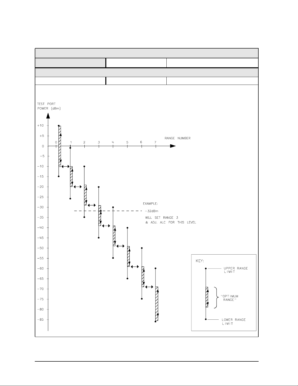
Table 1-31 Power Meter Calibration Sweep Speed and Accuracy
Power Desired at
Test Port
+5 dBm
−15 dBm
−30 dBm
a. Sweep speed applies to every sweep in continuous correction mode, and to the first
sweep in sample-and-sweep mode. Subsequent sweeps in sample-and-sweep mode
will be much faster.
b. The accuracy values were derived by combining the accuracy of the power meter and
linearity of the analyzer's internal source, as well as the mismatch uncertainty
associated with the power sensor.
Number of
Readings
1
2
3
1
2
3
1
2
3
Sweep Time
Setting (seconds)
33
64
95
48
92
123
194
360
447
Characteristic
a
Accuracy (dB)
±0.7
±0.2
±0.1
±0.7
±0.2
±0.1
±0.7
±0.2
±0.1
b
1-31

8753ES Specifications and Characteristics
Instrument Specifications
1-32

2 8753ET
Specifications and Characteristics
2-1

8753ET Specifications and Characteristics
Definitions
Definitions
All specifications and characteristics apply over a 25 °C ±5 °C range (unless otherwise
stated) and 1/2 hour after the instrument has been turned on.
Specification (spec.): Warranted performance. Specifications include guardbands to
account for the expected statistical performance distribution, measurement uncertainties,
and changes in performance due to environmental conditions.
Characteristic (char.): A performance parameter that the product is expected to meet
before it leaves the factory, but that is not verified in the field and is not covered by the
product warranty. A characteristic includes the same guardbands as a specification.
Typical (typ.): Expected performance of an average unit which does not include
guardbands. It is not covered by the product warranty.
Nominal (nom.): A general, descriptive term that does not imply a level of performance. It
is not covered by the product warranty.
Calibration: The process of measuring known standards from a calibration kit to
characterize a network analyzer’s systematic (repeatable) errors.
Corrected (residual) Performance: Indicates performance after error correction
(calibration). It is determined by the quality of calibration standards and how well
“known” they are, plus system repeatability, stability, and noise.
Uncorrected (raw) Performance: Indicates instrument performance without error
correction. The uncorrected performance affects the stability of a calibration.
Standard: When referring to the analyzer, this includes all options unless noted otherwise.
2-2

8753ET Specifications and Characteristics
Corrected System Performance
Corrected System Performance
The specifications in this section apply for measurements made using 10 Hz IF bandwidth,
no averaging, and at an environmental temperature of 25 ±5 °C, with less than 1 °C
deviation from the calibration temperature. Assumes that an isolation calibration was
performed with an averaging factor of 16.
Table 2-1 System Dynamic Range, All Device Connector Types
8753ET, All Options, All Cal Kits, All Cables, 10 Hz IF BW
Description Specification Supplemental
Information
System Transmission Dynamic Range
300 kHz to 16 MHz 100 dB
16 MHz to 1.3 GHz 110 dB
1.3 GHz to 3 GHz 110 dB
3 GHz to 6 GHz 105 dB
a
a. The System Transmission Dynamic Range is calculated as the difference
between the receiver noise floor and the lesser of either: the source maximum
output or the receiver maximum input.
2-3

8753ET Specifications and Characteristics
Corrected System Performance
Table 2-2 Type-N (50 Ω) Device Connector Type
Network Analyzer: 8753ET Standard or Option 004 Attenuator
Calibration Kit: 85032B/E (Type-N, 50 Ω)
Cables: 8120-5639 Cables
Calibration: See Below
IF BW = 10 Hz, Avg = off, Temp = 25 ± 5 °C with < 1 °C deviation from cal temp, Isol cal with avg = 8
Specification
Description
Reflection Measurements
Directivity (dB) 50 47 40
Source Match (dB) 42 36 31
Load Match
One-Port Cal 24 19 16
Tracking
Magnitude (dB) ±(0.009 + .01/°C) ±(0.019 + .02/°C) ±(0.07 + .03/°C)
Phase (deg) ±(0.059 + .05/°C) ±(0.125 + .05/°C) ±(0.462 + .2/°C)
Transmission Measurements
Source Match (dB)
Enhanced Response Cal 42 36 31
Response Only Cal
Standard 25 20 14
Option 004 23 18 14
Load Match 24 19 16
Tracking
Enhanced Response Cal
Magnitude (dB) ±(0.006 + .01/°C) ±(0.018 + .02/°C) ±(0.054 + .03/°C)
Phase (deg) ±(0.0396 + .05/°C) ±(0.119 + .05/°C) ±(0.389 + .20/°C)
Response Only Cal
Standard
Magnitude (dB) ±(0.031 + .01/°C) ±(0.1 + .02/°C) ±(0.27 + .03/°C)
Phase (deg) ±(0.203 + .05/°C) ±(0.66 + .05/°C) ±(1.78 + .20/°C)
Option 004
Magnitude (dB) ±(0.039 + .01/°C) ±(0.122 + .02/°C) ±(0.27 + .03/°C)
Phase (deg) ±(0.255 + .05/°C) ±(0.804 + .05/°C) ±(1.78 + .20/°C)
Uncertainty graphs are on the following page.
300 kHz to 1.3 GHz 1.3 to 3 GHz 3 to 6 GHz
(Opt 006 only)
a
b
a. One-port or enhanced response calibration.
b. Enhanced response or response only calibration.
2-4

8753ET Specifications and Characteristics
Corrected System Performance
Transmissiona Uncertainty: Enhanced Response Calibration (Specification)
Transmission Uncertainty: Response Calibration (Specification)
Reflection Uncertainty: One-Port Calibration (Specification)
a. Option 004 may degrade transmission source match as much as 2 dB, resulting in up to
0.05 dB additional uncertainty in transmission uncertainty.
2-5

8753ET Specifications and Characteristics
Instrument Specifications
Instrument Specifications
Uncorrected Port Performance
Table 2-3 Type-N (50 Ω) Device Connector Type
8753ET (Type-N, 50 Ω)
Specification
Description
300 kHz to
1.3 GHz
1.3 to 3 GHz 3 to 6 GHz
(Opt 006 only)
Directivitya (dB)
Source Match
Standard (dB) 25 20 14
Option 004 (dB) 23 18 14
Load Matcha (dB)
Reflection
Trackinga (dB)
Transmission
Trackinga (dB)
Tracking Stability
(Ratio Measurement)
Magnitude (db) .002/°C, typ. .002/°C, typ. .004/°C, typ.
Phase (deg) .004/°C, typ. .004/°C, typ. .020/°C, typ.
Crosstalkb (dB)
a. Does not include the effect of the cable set on the test ports.
b. Measurement conditions: Normalized to a thru, measured with two shorts, 10 Hz IF
bandwidth, averaging factor of 8, alternate mode, source power set to the lesser of the
maximum power out or the maximum receiver power.
a
30 24 19
24 19 16
±1.0 ±1.0 ±2.0
±1.5 ±1.5 ±2.5
100 100 90
2-6

8753ET Specifications and Characteristics
Instrument Specifications
Test Port Output
Table 2-4 Test Port Output
8753ET Test Port Output
Description Specification Supplemental Information
Frequency
Range
Standard 300 kHz to 3.0 GHz 10 kHz to 3 GHz, typ.
Option 006 300 kHz to 6.0 GHz 10 kHz to 6 GHz, typ.
Resolution 1 Hz
Stability
Standard ±7.5 ppm, 0° to 55 °C, typ.
±3 ppm/year, typ.
Option 1D5 ±0.05 ppm, 0° to 55 °C, typ.
±0.5 ppm/year, typ.
CW Accuracy ±10 ppm at 25 °C ±5 °C
Output Power (above 300 kHz)
Level Accuracy
With Option 004 Attenuator ±1.0 dB at −10 dBm output level
Without Attenuator ±1.0 dB at −5 dBm output level
Maximum Leveled Power
With Option 004 Attenuator +10 dBm, char.
Without Attenuator +5 dBm, char.
Power Range
With Option 004 Attenuator −85 to +10 dBm
Without Attenuator −20 to +5 dBm
Power Sweep Range
With Option 004 Attenuator 25 dB 33 dB, typ.
Without Attenuator 25 dB 33 dB, typ.
a
b
c
a. Absolute power accuracy at a given power level. Includes absolute accuracy and relative
flatness across frequency.
b. At any given frequency, the achievable power while remaining leveled. Applies to CW
mode only.
c. Power to which the source can be set and phase lock is assured.
2-7
8753ET Specifications and Characteristics
Instrument Specifications
Table 2-5 Test Port Output
8753ET Test Port Output
Description Specification Supplemental Information
Output Powera (above 300 kHz)
Power Resolution 0.01 dB
Attenuator Switch Points (Option 004 Only):
a. Source output performance on port 1 only. Port 2 output performance is a characteristic.
2-8

8753ET Specifications and Characteristics
Instrument Specifications
Table 2-6 Test Port Output
8753ET Test Port Output
Description Specification Supplemental Information
Output Power (above 300 kHz)
Linearity
Standard
−20 to −15 dBm ±0.5 dB relative to −5 dBm output level
−15 to 0 dBm ±0.2 dB relative to −5 dBm output level
0 to +5 dBm ±0.5 dB relative to −5 dBm output level
Option 004
−15 to +5 dBm ±0.2 dB relative to 0 dBm output level
+5 to +10 dBm ±0.5 dB relative to 0 dBm output level
Impedance
Standard 50 Ω, nom.
Return Loss
Standard
300 kHz to 3 GHz > 20 dB, typ.
3 GHz to 6 GHz > 14 dB, typ.
Option 004
300 kHz to 3 GHz > 18 dB, typ.
3 GHz to 6 GHz > 14 dB, typ.
Attenuator Accuracya(Option 004 only)
0 dB reference; at 50 MHz
300 kHz to 3 GHz 3 GHz to 6 GHz
10 dB ± 0.2 dB, char. ± 0.5 dB, char.
20 dB ± 0.4 dB, char. ± 0.7 dB, char.
30 dB ± 0.5 dB, char. ± 0.9 dB, char.
40 dB ± 0.7 dB, char. ± 1.2 dB, char.
50 dB ± 0.8 dB, char. ± 1.5 dB, char.
60 dB ± 1.0 dB, char. ± 1.8 dB, char.
a. The accuracy, relative to the 0 dB setting, of each setting of an attenuator, at a given
frequency.
2-9

8753ET Specifications and Characteristics
Instrument Specifications
Table 2-7 Test Port Output
8753ET Test Port Output
Description Specification Supplemental Information
Signal Purity
2nd Harmonic 16 MHz to 1.5 GHz (source frequency)
16 MHz to 3 GHz
(Option 006, source frequency)
at the maximum output
power
at 10 dB below maximum
output power
at 20 dB below maximum
output power
3rd Harmonic 16 MHz to 1 GHz (source frequency)
at the maximum output
power
at 10 dB below maximum
output power
at 20 dB below maximum
output power
Non-harmonic Spurious
Mixer Related
at maximum output power < −30 dBc, typ.
at 20 dB below maximum
output power
< −25 dBc, char. (Option 002)
< −40 dBc, typ.
< −50 dBc, typ.
16 MHz to 2 GHz
(Option 006, source frequency)
< −25 dBc, char. (Option 002)
< −40 dBc, typ.
< −50 dBc, typ.
< −55 dBc, typ.
2-10

8753ET Specifications and Characteristics
Instrument Specifications
Test Port Input
Table 2-8 Test Port Input
8753ET Test Port Input
Description Specification Supplemental Information
Frequency Range
Standard 300 kHz to 3.0 GHz 10 kHz to 3 GHz, typ.
Option 006 300 kHz to 6.0 GHz 10 kHz to 6 GHz, typ.
Frequency Response (Transmission)
300 kHz to 3 GHz ±1 dB at preset power level
3 GHz to 6 GHz ±2 dB at preset power level
Impedance
Standard 50 Ω, nominal.
Return Loss
Standard See uncorrected load match
chart.
Maximum Input Level
Transmission Port 0 dBm
Reflection Port +10 dBm
Compression See dynamic accuracy chart
Damage Level
Standard > +20 dBm or > 35 Vdc, typ.
Noise Floor
8753ET Transmission Port
300 kHz to 3 GHz
3 kHz IF Bandwidth ≤ −90 dBm
10 Hz IF Bandwidth ≤ −110 dBm ≤ −120 dBm, typ.
3 GHz to 6 GHz
3 kHz IF Bandwidth ≤ −85 dBm
10 Hz IF Bandwidth ≤ −105 dBm ≤ −114 dBm, typ.
a
a. RMS value of a linear magnitude trace expressed in dBm.
2-11

8753ET Specifications and Characteristics
Instrument Specifications
Table 2-9 Test Port Input
8753ET Test Port Input
Description Specification Supplemental Information
Internally Generated Harmonics (Option 002 Only)
2nd Harmonic 16 MHz to 3 GHz
at 0 dBm input level < −15 dBc, char.
at −10 dBm input level < −30 dBc, typ.
at −25 dBm input level < −45 dBc, typ.
3rd Harmonic 16 MHz to 2 GHz
at 0 dBm input level < −30 dBc, char.
at −10 dBm input level < −50 dBc, typ.
at −25 dBm input level < −50 dBc, typ.
Harmonic Measurement Accuracy
16 MHz to 3 GHz ±1.5 dB, char.
3 GHz to 6 GHz ±3 dB, char.
Harmonic Measurement Dynamic Range
Standard −40 dBc, typ.
output at −10 dBm and input
at < −15 dBm
2-12

8753ET Specifications and Characteristics
Instrument Specifications
Table 2-10 Test Port Input
8753ET Test Port Input
Description Specification Supplemental Information
Frequency Offset Operation
Frequency Range
Standard 300 kHz to 3 GHz
Option 006 300 kHz to 6 GHz
R Channel Input Requirements
300 kHz to 3 GHz 0 to −35 dBm
3 GHz to 6 GHz 0 to −30 dBm
LO Spectral Purity and
Accuracy
Maximum Spurious Input < −25 dBc, typ.
Residual FM < 20 kHz, typ.
Frequency Accuracy −1 to +1 MHz of nominal
External Source Mode
Frequency Range at − 25 dBm R channel power
Standard 300 kHz to 3 GHz
Option 006 300 kHz to 6 GHz
R Input Requirements
Power Level 0 to −25 dBm, typ.
R Input Spectral Purity
Requirement
Maximum Spurious Input < −30 dBc, typ.
Residual FM < 20 kHz, typ.
Settling Time
Auto 500 ms, typ.
Manual 50 ms, typ.
Frequency Readout Accuracy 0.1%, auto, typ.
Input Frequency Accuracy
Requirement
Manual −0.5 to 5 MHz, typ.
a
frequency, typ.
b
level
a. The RF source characteristics in this mode are dependent on the stability of the external
LO source. The RF source tracks the LO to maintain a stable IF signal at the R channel
receiver input.
b. Measurement accuracy is dependent on the stability of the input signal.
2-13

8753ET Specifications and Characteristics
Instrument Specifications
Table 2-11 Test Port Input
8753ET Test Port Input
Description
Trace Noise
Magnitude
300 kHz to 3GHz < 0.006 dB rms < 0.001 dB rms
3 GHz to 6 GHz < 0.010 dB rms < 0.002 dB rms
Phase
300 kHz to 3GHz < 0.038° rms < 0.006° rms
3 GHz to 6 GHz < 0.070° rms < 0.012° rms
a. Trace noise is defined for a ratio measurement. For the transmission
measurement (B/R), the connection is a 0 dB loss thru with 0 dBm into the
receiver. For a reflection measurement (A/R), an open is used on the
Reflection port with +5 dBm reflected power.
a
Specification
System Bandwidths
3000 Hz 10 Hz
Table 2-12 Test Port Input
8753ET Test Port Input
Description Specification Supplemental
Information
Reference Level
Magnitude
Range ± 500 dB
Resolution 0.001 dB
Phase
Range ± 500°
Resolution 0.01°
Stability (Ratio Measurement)
Magnitude
300 kHz to 3 GHz 0.02 dB/°C, typ.
3 GHz to 6 GHz 0.04 dB/°C, typ.
Phase
300 kHz to 3 GHz 0.05 deg/°C, typ.
3 GHz to 6 GHz 0.20 deg/°C, typ.
2-14
8753ET Specifications and Characteristics
Instrument Specifications
Table 2-13 Test Port Input
8753ET Test Port Input
Dynamic Accuracy (Characteristic)
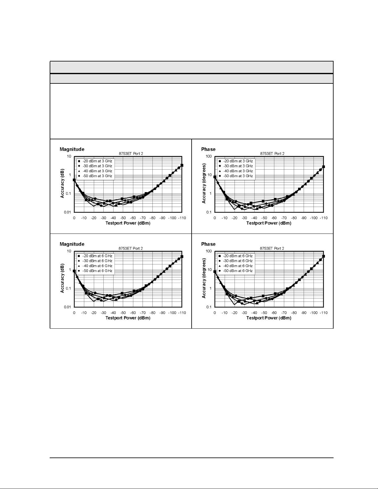
For the transmission port, accuracy of the test port input power reading relative to the reference
input power level.
• Input: transmission port
• For test port powers > −60 dBm and < −10 dBm, magnitude dynamic accuracy is
0.02 dB + 0.001 dB/dB from the reference power, phase dynamic accuracy is
0.132 deg + 0.0066 deg/dB from the reference power.
2-15

8753ET Specifications and Characteristics
Instrument Specifications
Table 2-14 Test Port Input
8753ET Test Port Input
Dynamic Accuracy (Characteristic)
For the reflection port, accuracy of the test port input power reading relative to the reference
input power level.
• Input: reflection port
• For test port powers > −50 dBm and < 0 dBm, magnitude dynamic accuracy is
0.02 dB + 0.001 dB/dB from the reference power, phase dynamic accuracy is
0.132 deg + 0.0066 deg/dB from the reference power.
• For frequencies < 2 MHz, the accuracy is degraded 0.1 dB above 5 dBm test port power.
2-16

8753ET Specifications and Characteristics
Instrument Specifications
Table 2-15 Test Port Input
8753ET R-Channel Input
Dynamic Accuracy (Typical)
Accuracy of the R-channel power reading relative to the R-channel reference power level.
This chart applies when the calibrated power level and the measurement power level are not the
same.
• Inputs: R-channel
300 KHz to 3 GHz 3 to 6 GHz
Magnitude Dynamic Accuracy
for Test Port Powers
> −50 dBm and < 0 dBm .02 dB + .001 dB/dB
from the reference power
> 0 dBm and < 10 dBm .02 dB + .02 dB/dB
above 0 dBm
Phase Dynamic Accuracy for
Test Port Powers
> −50 dBm and < 0 dBm .132 deg + .0066 deg/dB
from the reference power
> 0 dBm and < 10 dBm .132 deg + .132 deg/dB
above 0 dBm
.02 dB + .001 dB/dB
from the reference power
.02 dB + .03 dB/dB
above 0 dBm
.132 deg + .0066 deg/dB
from the reference power
.132 deg + .198 deg/dB
above 0 dBm
2-17

8753ET Specifications and Characteristics
Instrument Specifications
General Information
Table 2-16 General Information
8753ET General Information
Description Specification Supplemental Information
Display Range
Magnitude ±200 dB (at 20 dB/div), max
Phase ± 180°, max
Polar 10 pico units, min
1000 units, max
Display Resolution
Magnitude 0.001 dB/div, min
Phase 0.1°/div, min
Reference Level Range
Magnitude ± 500 dB, max
Phase ± 360°, max
Reference Level Resolution
Magnitude 0.001 dB, min
Phase 0.01°, min
Marker Resolution
Magnitude 0.001 dB, min
Phase 0.01°, min
Polar 0.01 mUnit, min; 0.01, min
2-18

8753ET Specifications and Characteristics
Instrument Specifications
Table 2-17 General Information
8753ET General Information
Description Specification Supplemental Information
Group Delay
Aperture (selectable) (frequency span)/(number of
Maximum Aperture 20% of frequency span
Range 1/2 × (1/minimum aperture)
Maximum Delay Limited to measuring no more
Accuracy See graph. Char.
The following graph shows group delay accuracy with 7-mm full 2-port calibration and a 10 Hz IF
bandwidth. Insertion loss is assumed to be < 2 dB and electrical length to be ten meters.
a
points − 1)
than 180° of phase change
within the minimum
aperture.)
In general, the following formula can be used to determine the accuracy, in seconds, of specific
group delay measurement:
±Relative Phase Accuracyb (deg)/[360 × Aperture (Hz)]
Depending on the aperture and device length, the phase accuracy used is either phase dynamic
accuracy specification or worst case transmission uncertainty phase specification.
a. Group delay is computed by measuring the phase change within a specified frequency
step (determined by the frequency span and the number of points per sweep).
b. Relative phase accuracy is an unspecified parameter. For very narrow apertures with
short devices under test RF systematic error terms can be assumed constant. As aperture
and/or device electrical length increase RF systematic errors become increasingly
important, eventually relative phase accuracy is the same as absolute phase accuracy.
2-19

8753ET Specifications and Characteristics
Instrument Specifications
Table 2-18 General Information
8753ET General Information
Description Supplemental Information
System Bandwidths
IF bandwidth settings 6000 Hz, nom.
3700 Hz, nom.
3000 Hz, nom.
1000 Hz nom.
300 Hz, nom.
100 Hz, nom.
30 Hz, nom.
10 Hz, nom.
Rear Panel
External Auxiliary Input
Connector Female BNC
Range 10 V, typ.
External Trigger Triggers on a positive or negative TTL transition or contact
closure to ground.
Damage Level < −0.2 V; > +5.2 V, typ.
Limit Test Output Female BNC.
Damage Level < −0.2 V; > +5.2 V, typ.
Test Sequence Output Outputs a TTL signal which can be set to a TTL high pulse
(default) or low pulse at end of sweep; or a fixed TTL high or
low. If limit test is on, the end of sweep pulse occurs after the
limit test is valid. This is useful when used in conjunction with
test sequencing.
Test Set Interconnect 25-pin-D-sub (DB-25) female; use for external special test sets
(K36, K39, etc.)
Measure Restart Floating closure to restart measurement.
External AM Input ± 1 volt into a 5 kΩ resistor, 1 kHz maximum, resulting in
approximately 8 dB/volt amplitude modulation.
High Stability Frequency
Reference Output (10 MHz)
(Option 1D5)
Frequency 10.0000 MHz, char.
Frequency Stability
(0 °C to 55 °C)
Daily aging rate (after 30 days)
Yearly aging rate ±0.5 ppm/year, char.
Output ≥ 0 dBm, char.
Output Impedance 50 Ω, nom.
±0.05 ppm, char.
< 3 x 10⁻⁹/day, char.
2-20

8753ET Specifications and Characteristics
Instrument Specifications
Table 2-19 General Information
8753ET General Information
Description Specification Supplemental Information
Rear Panel
External Reference In
Input Frequency 1, 2, 5, and 10 MHz ± 200 Hz at 10 MHz
Input Power −10 dBm to +20 dBm, typ.
Input Impedance 50 Ω, nom.
VGA Video Output 15-pin mini D-Sub; female. Drives
VGA compatible monitors.
GPIB Type-57, 24-pin; Microribbon
female
Parallel Port 25-pin D-Sub (DB-25); female;
may be used as printer port or
general purpose I.O. port
RS232 9-pin D-Sub (DB-9); male
Mini-DIN Keyboard/Barcode Reader 6-pin mini DIN (PS/2); female
Line Power A third-wire ground is required.
Frequency 47 Hz to 66 Hz
Voltage at 115 V setting 90 V to 132 V 115 V, nom.
Voltage at 220 V setting 198 V to 265 VAC 230 V, nom.
VA Maximum 350 VA max
Front Panel
RF Connectors Type-N, 50 ohm
Probe Power 3-pin connector; male
Positive Supply 400 mA, max +15 V ± 2%, char.
the maximum combined load for
both probe connectors, char.
Negative Supply 300 mA, max − 12.6 V ± 5%, char.
the maximum combined load for
both probe connectors, char.
2-21

8753ET Specifications and Characteristics
Instrument Specifications
Table 2-20 General Information
8753ET General Information
Description Specification
Front Panel
Display Pixel Integrity
Red, Green, or Blue Pixels Red, green, or blue "stuck on" pixels may
appear against a black background. In a
properly working display, the following will
not occur:
• complete rows or columns of stuck pixels
• more than 5 stuck pixels (not to exceed a
maximum of 2 red or blue, and 3 green)
• 2 or more consecutive stuck pixels
• stuck pixels less than 6.5 mm apart
Dark Pixels Dark "stuck on" pixels may appear against a
white background. In a properly working
display, the following will not occur:
• more than 12 stuck pixels (not to exceed a
maximum of 7 red, green, or blue)
• more than one occurrence of 2
consecutive stuck pixels
• stuck pixels less than 6.5 mm apart
2-22

8753ET Specifications and Characteristics
Instrument Specifications
Table 2-21 General Information
8753ET General Information
Description Specification Supplemental Information
General Environmental
RFI/EMI Susceptibility Defined by CISPR Pub. 11 and
FCC Class B standards.
ETD Minimize using static-safe
work procedures and an
antistatic bench mat
(part number 9300-0797).
Dust Minimize for optimum
reliability.
Operating Environment
Temperature 0 °C to +55 °C Instrument powers up, phase
locks, and displays no error
messages within this
temperature range.
Error-corrected temperature
range
Humidity 5% to 95% at +40 °C
(non-condensing)
Altitude 0 to 4.5 km (15,000 ft)
Storage Conditions
Temperature −40 °C to +70 °C
Humidity 0% to 95% RH at +65 °C
(non-condensing)
Altitude 0 to 15.24 km (50,000 ft)
Cabinet Dimensions
Height x Width x Depth 222 x 425 x 457 mm, nom.
Weight
Shipping 32 kg (77 lb), nom.
Net 24 kg (53 lb), nom.
Internal Memory - Data Retention Time with 3 V, 1.2 Ah Battery
70 °C 250 days (0.68 year), char.
40 °C 1244 days (3.4 years), char.
25 °C 10 years, char.
see system specifications
(8.75 x 16.75 x 18 in, nom.)
Cabinet dimensions exclude
front and rear protrusions.
a
a. Analyzer power is switched off.
2-23

8753ET Specifications and Characteristics
Instrument Specifications
Speed Parameters
Table 2-22 Measurement and Data Transfer Speed Performance
Typical Time for Completion (ms)
Description Number of Points
51 201 401 1601
Typical Time for Completion (in ms), Center 1 GHz, Span 10 MHz, IFBW=6000
Uncorrected 32 70 121 423
1-port and Enhanced Response cal
2-port cal
b
a
Typical Time for Completion (in ms), Center 30 kHz, Stop 3 GHz, IFBW=6000
Uncorrected 202 270 304 615
1-port and Enhanced Response cal 202 270 304 615
2-port cal 402 540 607 1237
Typical Time for Completion (in ms), Center 30 kHz, Stop 6 GHz, IFBW=6000
Uncorrected 310 380 415 658
1-port and Enhanced Response cal 310 380 415 658
2-port cal 618 757 829 1315
35 71 127 440
62 139 240 848
Time Domainc (increase over uncorrected sweep time)
Conversions 12 42 86 378
Gating (Frequency Domain) 14 40 80 349
GPIB Data Transferd:
Binary (Internal) 10 16 21 58
IEEE754 floating point format
32 bit 11 19 28 83
64 bit 13 26 42 141
ASCII 35 112 214 831
a. S11 1-port calibration, with a 6 kHz IF bandwidth. Includes system retrace time, but
does not include bandswitch time. Time domain gating is assumed off.
b. S21 measurement with full 2-port calibration, using a 6 kHz IF bandwidth. Includes
system retrace time and RF switching time, but does not include bandswitch time. Time
domain gating is assumed off.
c. Option 010 only, gating off.
d. Measured with HP Omnibook 7100 Pentium computer.
2-24

8753ET Specifications and Characteristics
Table 2-23 Recall and Sweep Speed Performance
Instrument Specifications
Total Time,
typical (secs)
Raw
Operations Channel Points
Error Correction
ON
Recall and Sweep Single Chan. 201 On 0.389 0.260 0.250 0.126
Recall and Sweep Single Chan. 201 Off 0.340 0.210 0.201 0.077
Sweep only (no Recall) Single Chan. 201 N/A 0.139 0.134 N/A N/A
Recall and Sweep Single Chan. 1601 On 1.480 1.347 0.632 0.506
Recall and Sweep Single Chan. 1601 Off 1.102 0.969 0.254 0.128
Sweep only (no Recall) Single Chan. 1601 N/A 0.848 0.841 N/A N/A
Recall and Sweep Dual Chan. 201 On 0.539 0.389 0.357 0.215
Recall and Sweep Dual Chan. 201 Off 0.489 0.328 0.308 0.154
Sweep only (no Recall) Dual Chan. 201 N/A 0.182 0.174 N/A N/A
Recall and Sweep Dual Chan. 1601 On 2.386 2.219 1.208 1.049
Recall and Sweep Dual Chan. 1601 Off 2.007 1.839 0.829 0.669
Sweep only (no Recall) Dual Chan. 1601 N/A 1.178 1.170 N/A N/A
Error Correction
OFF
Recall and Sweep Single Chan. 201 On 0.240 0.147 0.170 0.082
Recall and Sweep Single Chan. 201 Off 0.227 0.134 0.157 0.069
Sweep only (no Recall) Single Chan. 201 N/A 0.070 0.065 N/A N/A
Recall and Sweep Single Chan. 1601 On 0.675 0.587 0.252 0.168
Recall and Sweep Single Chan. 1601 Off 0.581 0.491 0.157 0.073
Sweep only (no Recall) Single Chan. 1601 N/A 0.423 0.419 N/A N/A
Recall and Sweep Dual Chan. 201 On 0.306 0.170 0.235 0.104
Recall and Sweep Dual Chan. 201 Off 0.281 0.145 0.211 0.080
Sweep only (no Recall) Dual Chan. 201 N/A 0.071 0.066 N/A N/A
Recall and Sweep Dual Chan. 1601 On 0.802 0.692 0.377 0.273
Recall and Sweep Dual Chan. 1601 Off 0.613 0.503 0.188 0.084
Sweep only (no Recall) Dual Chan. 1601 N/A 0.424 0.419 N/A N/A
Instrument State: CF = 1 GHz, Span = 2 MHz, IF BW = 6 kHz. GPIB commands sent for timing are
Recall;OPC?;SING; or, for sweep only, OPC?;SING;.
Offset
Blank
Off
BlankOnBlank
Recall-Only
Time, typical
(secs)
Blank
Off
On
2-25

8753ET Specifications and Characteristics
Instrument Specifications
Table 2-24 Sweep Time vs. IF Bandwidth
IF Bandwidth
Typical Sweep Time (seconds)
6000 0.070
3700 0.095
3000 0.121
1000 0.248
300 0.704
100 2.022
30 6.987
10 21.365
a. Preset condition, CF = 1 GHz, Span = 100 MHz; includes retrace time, 201 points.
Table 2-25 Sweep Time vs. Number of Points
Number of Points
Typical Sweep Time (seconds)
51 0.039
101 0.057
201 0.095
401 0.171
801 0.323
1601 0.625
a
a
a. Preset condition, CF = 1 GHz, Span = 100 MHz, Correction off; includes retrace time.
Measurement speed can be improved by selecting the widest IF bandwidth setting of 6000 Hz.
2-26

8753ET Specifications and Characteristics
Instrument Specifications
Power Meter Calibration Accuracy
Table 2-26 Power Meter Calibration Sweep Speed and Accuracy
Power Desired at
Test Port
+5 dBm 1
−15 dBm 1
−30 dBm 1
Number of
Readings
2
3
2
3
2
3
Sweep Time
Setting (seconds)
33
64
95
48
92
123
194
360
447
Characteristic
a
Accuracy (dB)
±0.7
±0.2
±0.1
±0.7
±0.2
±0.1
±0.7
±0.2
±0.1
a. Sweep speed applies to every sweep in continuous correction mode, and to the first
sweep in sample-and-sweep mode. Subsequent sweeps in sample-and-sweep mode
will be much faster.
b. The accuracy values were derived by combining the accuracy of the power meter and
linearity of the analyzer's internal source, as well as the mismatch uncertainty
associated with the power sensor.
b
2-27

8753ET Specifications and Characteristics
Instrument Specifications
2-28

3 Front/Rear Panel
3-1

Front/Rear Panel
Front Panel Features
Front Panel Features
CAUTION Do not mistake the line switch for the disk eject button. See the following
illustrations. If the line switch is mistakenly pushed, the instrument will be
turned off, losing all settings and data that have not been saved.
Figure 3-1 8753ES Front Panel
3-2

Figure 3-2 8753ET Front Panel
Front/Rear Panel
Front Panel Features
The location of the following front panel features and key function blocks is shown in
Figure 3-1 and Figure 3-2. These features are described in more detail later in this chapter,
and in Chapter 5 , “Hardkey/Softkey Reference.”
1. LINE switch. This switch controls ac power to the analyzer. 1 is on, 0 is
off.
2. Display. This shows the measurement data traces, measurement
annotation, and softkey labels. The display is divided into specific
information areas, illustrated in Figure 3-3.
3. Disk drive. This 3.5 inch floppy-disk drive allows you to store and recall
instrument states and measurement results for later analysis.
4. Disk eject button.
5. Softkeys. These keys provide access to menus that are shown on the
display.
6. STIMULUS function block. The keys in this block allow you to control
the analyzer source's frequency, power, and other stimulus functions.
7. RESPONSE function block. The keys in this block allow you to control
the measurement and display functions of the active display channel.
3-3

Front/Rear Panel
Front Panel Features
8. ACTIVE CHANNEL keys. The analyzer has two independent primary
channels and two auxiliary channels. These keys allow you to select the
active channel. Any function you enter applies to the selected channel.
9. The ENTRY block. This block includes the knob, the step
keys, the number pad, and the backspace key. These allow you to enter
numerical data and control the markers.
You can use the numeric keypad to select digits, decimal points, and a
minus sign for numerical entries. You must also select a units terminator
to complete value inputs.
The backspace key has two independent functions: it modifies entries, and
it turns off the softkey menu so that marker information can be moved off
of the grids and into the softkey menu area. For more details, refer to the
“Making Measurements” chapter in the user’s guide.
10. INSTRUMENT STATE function block. These keys allow you to control
channel-independent system functions such as the following:
• copying, save/recall, and GPIB controller mode
• limit testing
• external source mode
• tuned receiver mode
• frequency offset mode
• test sequence function
• harmonic measurements (Option 002)
• time domain transform (Option 010)
GPIB STATUS indicators are also included in this block.
11. key. This key returns the instrument to either a known factory
Preset
preset state, or a user preset state that can be defined. Refer to Chapter 8 ,
“Preset State and Memory Allocation” for a complete listing of the
instrument preset condition.
12. PROBE POWER connectors. These connector (fused inside the
instrument) supply power to an active probe for in-circuit measurements
of ac circuits.
13. R CHANNEL connectors. These connectors allow you to apply an input
signal to the analyzer's R channel, for frequency offset mode.
14. (ES) PORT 1 and PORT 2. These ports output a signal from the source and
receive input signals from a device under test. PORT 1 allows you to
measure S
and S11. PORT 2 allows you to measure S21 and S22.
12
14. (ET) REFLECTION and TRANSMISSION ports. The REFLECTION port
outputs a signal from the source and allows you to make reflection
measurements. The TRANSMISSION port receives input signals from a
device under test and allows you to make transmission measurements.
3-4

Analyzer Display
Figure 3-3 Analyzer Display (Single Channel, Cartesian Format)
Front/Rear Panel
Analyzer Display
The analyzer display shows various measurement information:
• The grid where the analyzer plots the measurement data.
• The currently selected measurement parameters.
• The measurement data traces.
Figure 3-3 illustrates the locations of the different information labels described below.
In addition to the full-screen display shown in the illustration above, multi-graticule and
multi-channel displays are available, as described in the “Making Measurements” chapter
of the user’s guide.
Several display formats are available for different measurements, as described under
" " in Chapter 5 , “Hardkey/Softkey Reference.”
Format
1. Stimulus Start Value. This value could be any one of the following:
• The start frequency of the source in frequency domain measurements.
• The start time in CW mode (0 seconds) or time domain measurements.
• The lower power value in power sweep.
When the stimulus is in center/span mode, the center stimulus value is
shown in this space. The color of the stimulus display reflects the current
active channel.
3-5

Front/Rear Panel
FREQUENCY BLANK
Analyzer Display
2. Stimulus Stop Value. This value could be any one of the following:
• The stop frequency of the source in frequency domain measurements.
• The stop time in time domain measurements or CW sweeps.
• The upper limit of a power sweep.
When the stimulus is in center/span mode, the span is shown in this space.
The stimulus values can be blanked, as described under the
softkey in Chapter 5 , “Hardkey/Softkey
Reference.”
(For CW time and power sweep measurements, the CW frequency is
displayed centered between the start and stop times or power values.)
3. Status Notations. This area shows the current status of various
functions for the active channel.
The following notations are used:
Avg Sweep-to-sweep averaging is on. The averaging count is
shown immediately below. (See the key in Chapter
Avg
5 , “Hardkey/Softkey Reference.”)
Cor Error correction is on. (For error-correction procedures,
refer to the "Calibrating for Increased Measurement
Accuracy" chapter in the user’s guide. For error correction
theory, refer to the “Operating Concepts” chapter of the
user’s guide.
C∆ Stimulus parameters have changed from the
error-correctedstate, or interpolated error correction is on.
(For error-correction procedures, refer to the "Calibrating
for Increased Measurement Accuracy" chapter in the
user’s guide. For error correction theory, refer to the
“Operating Concepts” chapter of the user’s guide.
C2 (ES) Full two-port error-correction is on and the reverse sweep
is not updated each sweep
Any one of the following causes the reverse sweep not to be
updated each sweep:
• the instrument uses a mechanical switch, for example
Options 85 and 007.
3-6
• different channel power ranges (PORT POWER
UNCOUPLED) which puts the test set switch in HOLD
mode except Option 400 (dual step attenuators).
• the user manually puts the test set switch in HOLD
mode (TESTSET SW 0 or >1).

Front/Rear Panel
HOLD
POWER
Analyzer Display
Del Electrical delay has been added or subtracted, or port
extensions are active. (See the “Operatiing Concepts”
chapter of the user’s guide and the key in
Scale Ref
Chapter 5 , “Hardkey/Softkey Reference.”)
ext Waiting for an external trigger.
Ofs Frequency offset mode is on. (See the “Making Mixer
Measurements” chapter in the user’s guide.)
Of? Frequency offset mode error, the IF frequency is not
within 10 MHz of expected frequency. LO inaccuracy is the
most likely cause. (See the “Making Mixer Measurements”
chapter in the user’s guide.)
Gat Gating is on (time domain Option 010 only). (For time
domain measurement procedures and theory, refer to the
"Making Time Domain Measurements" chapter of the
user’s guide.)
H=2 Harmonic mode is on, and the second harmonic is being
measured (harmonics Option 002 only). (See Chapter 7 ,
“Options and Accessories.”)
H=3 Harmonic mode is on, and the third harmonic is being
measured (harmonics Option 002 only). (See Chapter 7 ,
“Options and Accessories.”)
Hld Hold sweep. (See inChapter 5 , “Hardkey/Softkey
Reference.”)
man Waiting for manual trigger.
PC Power meter calibration is on. (For power meter
calibration procedures, refer to the "Calibrating for
Increased Measurement Accuracy" chapter of the user’s
guide.)
PC? The analyzer's source could not be set to the desired level,
following a power meter calibration. (For power meter
calibration procedures, refer to the "Calibrating for
Increased Measurement Accuracy" chapter in the user’s
guide.)
P? Source power is unleveled at start or stop of sweep. (Refer
to the service guide for troubleshooting.)
P↓ Source power has been automatically set to minimum, due
to receiver overload. (See in Chapter 5 ,
“Hardkey/Softkey Reference.”)
PRm (ES or ET Option 004.) Power range is in manual mode.
Smo Trace smoothing is on. (See " " in Chapter 5 ,
Avg
“Hardkey/Softkey Reference.”)
3-7

Front/Rear Panel
MEASURE RESTART
NUMBER OF GROUPS
Analyzer Display
tsH (ES or ET Option 004.) Indicates that the test set hold
mode is engaged. That is, a mode of operation is selected
which would cause repeated switching of the step
attenuator. This hold mode may be overridden. See
or in
Chapter 5 , “Hardkey/Softkey Reference.”
↑ Fast sweep indicator. This symbol is displayed in the
status notation block when sweep time is ≤1.0 second.
When sweep time is ≥ 1.0 second, this symbol moves along
the displayed trace.
* Source parameters changed: measured data in doubt until
a complete fresh sweep has been taken.
4. Active Entry Area. This displays the active function and its current
value.
5. Message Area. This displays prompts or error messages.
6. Title. This is a descriptive alphanumeric string title that you define and
enter through an attached keyboard or as described the "Printing,
Plotting, and Saving Measurement Results" chapter of the user’s guide.
7. Active Channel. This is the label for the number for the active channel,
selected with the , , , and keys.
Chan 1 Chan 2 Chan 3 Chan 4
If multiple channels are overlaid, the labels will appear in this area. The
active channel is denoted by a rectangle around the channel number.
For multiple-graticule displays, the channel information labels will be in
the same relative position for each graticule.
NOTE The label of the active channel is enclosed in a rectangle to differentiate it
from inactive channels.
8. Measured Input(s). This shows the parameter, input, or ratio of inputs
currently measured, as selected using the key. Also indicated in
Meas
this area is the current display memory status.
9. Format. This is the display format that you selected using the
Format
key.
10. Scale/Div. This is the scale that you selected using the key, in
Scale Ref
units appropriate to the current measurement.
11. Reference Level. This value is the reference line in Cartesian formats or
the outer circle in polar formats, whichever you selected using the
Scale Ref
key. The reference level is also indicated by a small triangle
adjacent to the graticule, at the left for channel 1 and at the right for
channel 2 in Cartesian formats.
3-8

Front/Rear Panel
Analyzer Display
12. Marker Values. These are the values of the active marker, in units
appropriate to the current measurement. (Refer to "Using Analyzer
Display Markers" in the "Making Measurement" chapter of the user’s
guide.)
13. Marker Stats, Bandwidth. These are statistical marker values that the
analyzer calculates when you access the menus with the key.
Marker Fctn
(Refer to "Using Analyzer Display Markers" in the "Making
Measurements" chapter of the user’s guide.)
This general area is also where information for additional markers is
placed. Note that Stats and Bandwidth have priority.
14. Softkey Labels. These menu labels redefine the function of the softkeys
that are located to the right of the analyzer display.
15. Pass Fail. During limit testing, the result will be annunciated as PASS if
the limits are not exceeded, and FAIL if any points exceed the limits.
3-9

Front/Rear Panel
Rear Panel Features and Connectors
Rear Panel Features and Connectors
Figure 3-4 8753ET/ES Rear Panel
Figure 3-4 illustrates the features and connectors of the rear panel, described below.
Requirements for input signals to the rear panel connectors are provided in the
specifications and characteristics chapter.
1. GPIB connector. This allows you to connect the analyzer to an external
controller, compatible peripherals, and other instruments for an
automated system. Refer to Chapter 7 , “Options and Accessories” for
GPIB information, limitations, and configurations.
2. PARALLEL interface. This connector allows the analyzer to output to a
peripheral with a parallel input. Also included, is a general purpose
input/output (GPIO) bus that can control eight output bits and read five
input bits through test sequencing. Refer to Chapter 7 , “Options and
Accessories” for information on configuring a peripheral. Also refer to The
GPIO Mode” in “Operating Concepts” of the user’s guide.
3. RS-232 interface. This connector allows the analyzer to output to a
peripheral with an RS-232 (serial) input.
4. KEYBOARD input (mini-DIN). This connector allows you to connect an
external keyboard. This provides a more convenient means to enter a title
for storage files, as well as substitute for the analyzer's front panel
keyboard.
5. Power cord receptacle, with fuse. For information on replacing the
fuse, refer to the installation and quick start guide.
3-10

Front/Rear Panel
MEASURE RESTART
Rear Panel Features and Connectors
6. Line voltage selector switch. For more information, refer to the
installation and quick start guide.
7. Fan. This fan provides forced-air cooling for the analyzer.
8. 10 MHZ PRECISION REFERENCE OUTPUT. (Option 1D5)
9. 10 MHZ REFERENCE ADJUST. (Option 1D5)
10. EXTERNAL REFERENCE INPUT connector. This allows for a
frequency reference signal input that can phase lock the analyzer to an
external frequency standard for increased frequency accuracy.
The analyzer automatically enables the external frequency reference
feature when a signal is connected to this input. When the signal is
removed, the analyzer automatically switches back to its internal
frequency reference.
11. AUXILIARY INPUT connector. This allows for a dc or ac voltage input
from an external signal source, such as a detector or function generator,
which you can then measure, using the S-parameter menu. (You can also
use this connector as an analog output in service routines, as described in
the service guide.)
12. EXTERNAL AM connector. This allows for an external analog signal
input that is applied to the ALC circuitry of the analyzer's source. This
input analog signal amplitude modulates the RF output signal.
13. EXTERNAL TRIGGER connector. This allows connection of an
external negative-going TTL-compatible signal that will trigger a
measurement sweep. The trigger can be set to external through softkey
functions.
14. TEST SEQUENCE. This outputs a TTL signal that can be programmed
in a test sequence to be high or low, or pulse (10 µseconds) high or low at
the end of a sweep for robotic part handler interface.
15. LIMIT TEST. This outputs a TTL signal of the limit test results as
follows:
• Pass: TTL high
• Fail: TTL low
16. MEASURE RESTART. This allows the connection of an optional foot
switch. Using the foot switch will duplicate the key sequence
Meas
17. TEST SET INTERCONNECT. Not used in standard configuration.
18. BIAS INPUTS AND FUSES. These connectors bias devices connected to
port 1 and port 2. The fuses (1 A, 125 V) protect the port 1 and port 2 bias
lines.
19. Serial number plate. The serial number of the instrument is located on
20. EXTERNAL MONITOR: VGA. VGA output connector provides analog
this plate.
red, green, and blue video signals which can drive a VGA monitor.
3-11

Front/Rear Panel
Rear Panel Features and Connectors
3-12

4 Menu Maps
4-1

Menu Maps
Menu Maps
Menu Maps
This chapter contains menus maps for the hardkeys listed below. The figure number of
these menu maps is listed next to the name of the hardkey. Fold Outs are located at the
end of this chapter.
Table 4-1 Menu Map Locations
Menu Map Figure Number Menu Map Figure Number
Avg
Cal
(ET Models)
Cal
(ES Models)
Copy
Display
Format
Local
Marker, Marker Fctn, and
Marker Search
Meas
(ET Models)
Figure 4-1
Fold Out
Fold Out
Figure 4-2
Figure 4-3
Figure 4-4
Figure 4-5
Figure 4-6
Figure 4-7
Figure 4-1 Menu Map for Avg
Meas
(ES Models)
Power & Sweep Setup
(ET Models)
Power and Sweep Setup
(ES Models)
Preset
Save/Recall
Scale Ref
Seq
System
(ET Models)
System
(ES Models)
Figure 4-8
Figure 4-9
Figure 4-10
Figure 4-11
Figure 4-12
Figure 4-13
Fold Out
Fold Out
Fold Out
4-2

Figure 4-2 Menu Map for Copy
Menu Maps
Menu Maps
4-3

Menu Maps
Menu Maps
Figure 4-3 Menu Map for Display
4-4

Figure 4-4 Menu Map for Format
Menu Maps
Menu Maps
4-5

Menu Maps
Menu Maps
Figure 4-5 Menu Map for Local
4-6

Figure 4-6 Menu Map for Marker, Marker Fctn, and Marker Search
Menu Maps
Menu Maps
4-7

Menu Maps
Menu Maps
Figure 4-7 Menu Map for Meas (ET Models only)
Meas
S-Parameter
Menu
REFLECTION
TRANSMISSN
ANALOG IN
Aux Input
CONVERSION
[]
INPUT
PORTS
*
* Aux input menu appears only when the analog bus
on OFF (service menu key under the system hardkey)
is turned to ON.
Aux Input
Menu
RESOLUTION
[LOW]
AUX OUT
on OFF
COUNTER:
OFF
ANALOG BUS
FRAC N
DIV FRAC N
RETURN
Conversion
Menu
OFF
Z:Ref l
Z:Trans
Y: Ref I
Y:Trans
1/S
RETURN
Input Ports
Menu
A/R
B/R
A/B
RETURN
ka513e
A
B
R
4-8

Figure 4-8 Menu Map for Meas (ES Models only)
Menu Maps
Menu Maps
4-9

Menu Maps
Menu Maps
Figure 4-9 Menu Map for Power and Sweep Setup (ET only)
4-10

Figure 4-10 Menu Map for Power and Sweep Setup (ES only)
Menu Maps
Menu Maps
4-11

Menu Maps
Menu Maps
Figure 4-11 Menu Map for Preset
4-12

Figure 4-12 Menu Map for Save/Recall
Menu Maps
Menu Maps
4-13

Menu Maps
Menu Maps
Figure 4-13 Menu Map for Scale Ref
4-14

Cal Kit
Menu
SELECT
CAL KIT
SAVE
USER KIT
MODIFY
RETURN
[ ]
Cal
Select Cal Kit
Menu
7mm
85031
3.5mmC
85033C
3.5mmD
85033D
N 50W
85032
N 75W
85036
USER KIT
MORE
RETURN
Correction
Menu
CORRECTION
on OFF
INTERPOL
ON off
CALIBRATE
MENU
RESUME CAL
SEQUENCE
CAL KIT
[ ]
PWRMTR CAL
[OFF]
MORE
Select Cal Kit
More Menu
2.4mm
85056
2.92 *
85056K
2.92mm
other kits
TRL 3.5mm
85052C
7-16
85038
RETURN
Power Meter
Cal. Main Menu
PWRMTR CAL
OFF
EACH SWEEP
ONE SWEEP
TAKE CAL
SWEEP
NUMBER of
READINGS
PWR LOSS
on OFF
LOSS/SENSR
LISTS
RETURN
Calibrate
More Menu
PORT
EXTENSIONS
VELOCITY
FACTOR
SET Z
ALTERNATE
RFL/TRN
CHOP
RFL/TRN
RETURN
Pwr. Loss/Sens.
Lists Menu
USE SENSOR
Æ
A / B
CAL FACTOR
SENSOR A
CAL FACTOR
SENSOR B
POWER
LOSS
RETURN
Segment
Modify Menu
SEGMENT
DELETE
Calibration Factor Softkey Path
Power Loss Softkey Path
Reference
Plane Menu
EXTENSIONS
on OFF
EXTENSION
INPUT A
EXTENSION
INPUT B
EXTENSION
REFL PORT
EXTENSION
TRANS PORT
RETURN
EDIT
ADD
CLEAR
LIST
DONE
Modify Cal Kit
Menu
DEFINE
STANDARD
SPECIFY
CLASS
LABEL
CLASS
LABEL
KIT
TRL/LRM
OPTION
KIT DONE
(MODIFIED)
Seg. Edit (Cal
Factor) Menu
FREQUENCY
CAL
FACTOR
DONE
Specify Class
Menu
S11A
S11B
S11C
S22A
S22B
S22C
MORE
SPECIFY
CLASS DONE
Seg. Edit (Pwr.
Loss) Menu
FREQUENCY
LOSS
DONE
Specify Class
More Menu
FWD TRANS
REV TRANS
FWD MATCH
REV MATCH
RESPONSE
RESPONSE
& ISOL'N
MORE
SPECIFY
CLASS DONE
Clear List
Menu
CLEAR LIST
YES
NO
Specify Class
More Menu
SPECIFY:
TRL THRU
TRL
REFLECT
TRL LINE
OR MATCH
SPECIFY
CLASS DONE
Calibrate
Menu
ENHANCED
RESPONSE
RESPONSE
RESPONSE
& ISOL'N
REFLECTION
1-PORT
RECEIVER
CAL
Enhanced
Response Menu
TRAN / REFL
ENH. RESP.
RETURN
Response &
Isolation Menu
RESPONSE
ISOL 'N STD
DONE RESP
ISOL 'N CAL
Enh. Resp.
Cal. Menu
REFLECT'N
TRANS-
MISSION
ISOLATION
DONE FWD
ENH RESP
Response
Menu
SHORT (M)
SHORT (F)
OPEN (M)
OPEN (F)
THRU
Enh. Resp.
Refl. Menu
FORWARD:
OPENS
SHORTS
LOAD
STANDARDS
DONE
Reflection
1-Port Menu
FORWARD:
OPENS
SHORTS
LOAD
DONE
1-PORT CAL
Enh. Resp.
Trans. Menu
DO BOTH
FWD THRUS
FWD TRANS
THRU
FWD MATCH
THRU
STANDARDS
DONE
Shorts
Menu
SHORT (M)
SHORT (F)
DONE:
SHORTS
Enh. Resp.
Isolation Menu
OMIT
ISOLATION
FWD ISOL'N
ISOLATION
DONE
Rcvr Cal
Menu
TAKE RCVR
CAL SWEEP
RETURN
Opens
Menu
OPEN ( M )
OPEN ( F )
DONE:
OPENS
ka527e
TRL Option
Menu
CAL Z0:
LINE Z0
SYSTEM Z0
SET REF:
THRU
REFLECT
RETURN
Label Class
Menu
S11A
S11B
S11C
S22A
S22B
S22C
MORE
LABEL
CLASS DONE
Label Class
More Menu
FWD TRANS
REV TRANS
FWD MATCH
REV MATCH
RESPONSE
RESPONSE
& ISOL'N
MORE
LABEL
CLASS DONE
Label Class / Kit
More Menu
LABEL:
TRL THRU
TRL
REFLECT
TRL LINE
OR MATCH
LABEL
CLASS DONE
Label Select
Menu
SELECT
LETTER
SPACE
BACK
SPACE
ERASE
TITLE
DONE
Define Standard
Menu
STD TYPE:
OPEN
SHORT
LOAD
DELAY /
THRU
ARBITRARY
IMPEDANCE
MODIFY STD
DEFINITION
RETURN
Def. Arbitrary
Imped. Menu
TERMINAL
IMPEDANCE
FIXED
SLIDING
SPECIFY
OFFSET
LABEL
STD
STD DONE
(DEFINED)
Define Delay/
Thru Menu
SPECIFY
OFFSET
LABEL
STD
STD DONE
(DEFINED)
Define Load
Menu
FIXED
SLIDING
OFFSET
SPECIFY
OFFSET
LABEL
STD
STD DONE
(DEFINED)
Define Short
Menu
SPECIFY
OFFSET
LABEL
STD
STD DONE
(DEFINED)
Define Open
Menu
SPECIFY
OFFSET
LABEL
STD
STD DONE
(DEFINED)
C0
C1
C2
C3
Specify Offset
Menu
OFFSET
DELAY
OFFSET
LOSS
OFFSET
MINIMUM
FREQUENCY
MAXIMUM
FREQUENCY
COAX
WAVEGUIDE
STD OFFSET
DONE
Z0
Label Standard
Menu
SELECT
LETTER
SPACE
BACK
SPACE
ERASE
TITLE
DONE
Menu Map For Cal (8753ET) only

Cal
Cal Kit
Menu
SELECT
CAL KIT
SAVE
USER KIT
MODIFY
[ ]
RETURN
Correction
Menu
CORRECTION
on OFF
INTERPOL
ON off
CALIBRATE
MENU
RESUME CAL
SEQUENCE
CAL KIT
[ ]
PWRMTR CAL
[OFF]
MORE
Select Cal Kit
Menu
7mm
85031
3.5mmC
85033C
3.5mmD
85033D
N 50W
85032
N 75W
85036
USER KIT
MORE
RETURN
Power Meter
Cal. Main Menu
PWRMTR CAL
EACH SWEEP
ONE SWEEP
TAKE CAL
SWEEP
NUMBER of
READINGS
PWR LOSS
on OFF
LOSS/SENSR
RETURN
Select Cal Kit
More Menu
2.4mm
85056
2.92 *
85056K
2.92mm
other kits
TRL 3.5mm
85052C
7-16
85038
RETURN
OFF
LISTS
Pwr. Loss/Sens.
Lists Menu
USE SENSOR
CAL FACTOR
SENSOR A
CAL FACTOR
SENSOR B
Calibrate
More Menu
PORT
EXTENSIONS
VELOCITY
FACTOR
SET Z
ADAPTER
REMOVAL
TESTSET SW
CONTINUOUS
ALTERNATE
A and B
CHOP
A and B
RETURN
Segment
Modify Menu
A / B
POWER
LOSS
RETURN
Calibration Factor Softkey Path
Power Loss Softkey Path
Adapter
Removal Menu
HELP ADAPT
REMOVAL
RECALL CAL
STETS
Æ
ADAPTER
DELAY
ADAPTER:
COAX
WAVEGUIDE
REMOVE
ADAPTER
RETURN
SEGMENT
EDIT
DELETE
ADD
CLEAR
LIST
DONE
Recall Cal Sets
Menu
RECALL
CAL PORT 1
RECALL
CAL PORT 2
RETURN
Seg. Edit (Cal
Factor) Menu
FREQUENCY
CAL
FACTOR
DONE
Reference
Plane Menu
EXTENSIONS
EXTENSION
EXTENSION
EXTENSION
EXTENSION
on OFF
INPUT A
INPUT B
PORT 1
PORT 2
RETURN
Seg. Edit (Pwr.
Loss) Menu
FREQUENCY
LOSS
DONE
Modify Cal Kit
Menu
STANDARD
SPECIFY
TRL/LRM
KIT DONE
(MODIFIED)
DEFINE
CLASS
LABEL
CLASS
LABEL
KIT
OPTION
Clear List
Menu
CLEAR LIST
YES
NO
Specify Class
Menu
S11A
S11B
S11C
S22A
S22B
S22C
MORE
SPECIFY
CLASS DONE
Specify Class
More Menu
FWD TRANS
REV TRANS
FWD MATCH
REV MATCH
RESPONSE
RESPONSE
& ISOL'N
MORE
SPECIFY
CLASS DONE
Define Standard
Menu
STD TYPE:
OPEN
SHORT
LOAD
DELAY /
THRU
ARBITRARY
IMPEDANCE
MODIFY STD
DEFINITION
RETURN
Specify Class
More Menu
TRL THRU
OR MATCH
CLASS DONE
SPECIFY:
TRL
REFLECT
TRL LINE
SPECIFY
Def. Arbitrary
Imped. Menu
TERMINAL
IMPEDANCE
FIXED
SLIDING
SPECIFY
OFFSET
LABEL
STD
STD DONE
(DEFINED)
Calibrate
ENHANCED
RESPONSE
RESPONSE
RESPONSE
TRL /LRM
RECEIVER
Menu
& ISOL'N
S11
1-PORT
S22
1-PORT
FULL
2-PORT
**
2-PORT
CAL
Define Delay/
Thru Menu
SPECIFY
OFFSET
LABEL
STD
STD DONE
(DEFINED)
Enhanced
Response Menu
ENH. RESP.
ENH. RESP.
S11/S21
S22/S12
RETURN
Define Load
Menu
FIXED
SLIDING
OFFSET
SPECIFY
OFFSET
LABEL
STD
STD DONE
(DEFINED)
Enh. Resp.
Cal. Menu
REFLECT'N
TRANS-
MISSION
ISOLATION
DONE
***
ENH RESP
Define Short
Menu
SPECIFY
OFFSET
LABEL
STD
STD DONE
(DEFINED)
Enh. Resp.
Refl. Menu
STANDARDS
***
OPENS
SHORTS
LOAD
DONE
:
Define Open
Menu
SPECIFY
OFFSET
LABEL
STD
STD DONE
(DEFINED)
Enh. Resp.
Trans. Menu
STANDARDS
C0
C1
C2
C3
DO BOTH
THRUS
***
TRANS
***
MATCH
***
THRU
THRU
DONE
Specify Offset
Menu
OFFSET
DELAY
OFFSET
LOSS
OFFSET
MINIMUM
FREQUENCY
MAXIMUM
FREQUENCY
COAX
WAVEGUIDE
STD OFFSET
DONE
Enh. Resp.
Isolation Menu
ISOLATION
***
ISOLATION
Z0
ISOL'N
OMIT
DONE
Label Standard
Menu
SELECT
LETTER
SPACE
BACK
SPACE
ERASE
TITLE
DONE
Response
Menu
SHORT (M)
SHORT (F)
OPEN (M)
OPEN (F)
THRU
Represents "FWD" when calibrating
***
the forward path or "REV" when calibrating
the reverse path
Response &
Isolation Menu
RESPONSE
ISOL 'N STD
DONE RESP
ISOL 'N CAL
Shorts
Menu
SHORT (M)
SHORT (F)
DONE:
SHORTS
ka526e
TRL Option
Menu
CAL Z0:
LINE Z0
SYSTEM Z0
SET REF:
THRU
REFLECT
RETURN
Label Class
Menu
S11A
S11B
S11C
S22A
S22B
S22C
MORE
LABEL
CLASS DONE
Label Class
More Menu
FWD TRANS
REV TRANS
FWD MATCH
REV MATCH
RESPONSE
RESPONSE
& ISOL'N
MORE
LABEL
CLASS DONE
Label Class
More Menu
LABEL:
TRL THRU
TRL
REFLECT
TRL LINE
OR MATCH
LABEL
CLASS DONE
Label Select
Kit Menu
SELECT
LETTER
SPACE
BACK
SPACE
ERASE
TITLE
DONE
Rcvr Cal
Menu
TAKE RCVR
CAL SWEEP
RETURN
TRL*/LRM*
Cal Menu
THRU
THRU
S11 REFL
OPENS
S22 REFL
OPENS
ISOLATION
LINE/MATCH
DONE
TRL/LRM
TRL*/LRM*
Isolation Menu
OMIT
ISOLATION
DO BOTH
FWD + REV
FWD ISOL 'N
ISOL 'N STD
REV ISOL 'N
ISOL 'N STD
ISOLATION
DONE
Line / Match
Menu
DO BOTH
FWD + REV
LN/MATCH1
LOAD
LN/MATCH2
LOAD
DONE
LINE / MATCH
2-Port Trans.
Menu
DO BOTH
FWD + REV
FWD TRANS
THRU
FWD MATCH
THRU
REV TRANS
THRU
REV MATCH
THRU
STANDARDS
DONE
2-Port Isolation
Menu
OMIT
ISOLATION
DO BOTH
FWD + REV
FWD ISOL 'N
ISOL 'N STD
REV ISOL 'N
ISOL 'N STD
ISOLATION
DONE
Full 2-Port
Menu
REFLECTION
TRANS-
MISSION
ISOLATION
DONE
2-PORT CAL
2-Port Reflection
Menu
FORWARD:
OPENS
SHORTS
LOAD
REVERSE:
OPENS
SHORTS
LOAD
STANDARDS
DONE
S22 1-Port
Menu
REVERSE:
OPENS
SHORTS
LOAD
DONE
1-PORT CAL
S11 1-Port
Menu
FORWARD:
OPENS
SHORTS
LOAD
DONE
1-PORT CAL
Opens
Menu
OPEN (M)
OPEN (F)
DONE:
OPENS
Menu Map For Cal (8753ES only)

Seq
Sequencing
Menu
CONTINUE
SEQUENCE
DO
SEQUENCE
GOSUB
SEQUENCE
NEW SEQ/
MODIFY SEQ
DONE SEQ
MODIFY
TTL I/O
SPECIAL
FUNCTIONS
MORE
Select Seq
Menu
SEQUENCE X
SEQ X
PAUSE TO
SELECT
RETURN
A
New / Modify
Seq Menu
SEQUENCE 1
SEQ 1
SEQUENCE 2
SEQ 2
SEQUENCE 3
SEQ 3
SEQUENCE 4
SEQ 4
SEQUENCE 5
SEQ 5
SEQUENCE 6
SEQ 6
*
RETURN
TTL I/O
Menu
TTL OUT
PARALLEL
OUT ALL
SET BIT
CLEAR BIT
PARALL IN
BIT NUMBER
PARALL IN
IF BIT H
IF BIT L
RETURN
TTL Out
Menu
TTL OUT
HIGH
TTL OUT
LOW
END SWEEP
HIGH PULSE
END SWEEP
LOW PULSE
TESTSET
I/O FWD
I/O REV
RETURN
Seq Spec
Func Menu
DECISION
MAKING
PERIPHERAL
HPIB ADDR
TITLE TO
PERIPHERAL
WAIT x
PAUSE
MARKER------
CW
MORE
RETURN
Seq Dec
Making Menu
IF LIMIT
TEST PASS
IF LIMIT
TEST FAIL
LOOP
COUNTER
INCR LOOP
COUNTER
DECR LOOP
COUNTER
IF LOOP
COUNTER=0
IF LOOP
COUNTER<>0
RETURN
New / Modify
Seq Menu
SEQUENCE 1
SEQ 1
SEQUENCE 2
SEQ 2
SEQUENCE 3
SEQ 3
SEQUENCE 4
SEQ 4
SEQUENCE 5
SEQ 5
SEQUENCE 6
SEQ 6
RETURN
Spec Func
More Menu
EMIT
BEEP
TITLE TO
PRNTR/GPIB
TITLE TO
P MTR/GPIB
SHOW
MENUS
ASSERT SRQ
P MTR/GPIB
TO TITLE
TITLE TO
MEMORY
RETURN
Sequencing
More Menu
STORE SEQ
FROM DISK
DUPLICATE
SEQUENCE
SEQUENCE
SEQUENCE
SEQUENCE
A
Displays only the user-defined sequence (X),
where X is the sequence number, when not modifying
a sequence. When modifying a sequence all sequence
labels are shown.
TO DISK
LOAD SEQ
PRINT
TITLE
CLEAR
RETURN
Select Seq
Menu
SEQUENCE X
SEQX
RETURN
A
Select Seq
Menu2
SEQUENCE 1
SEQ 1
SEQUENCE 2
SEQ 2
SEQUENCE 3
SEQ 3
SEQUENCE 4
SEQ 4
SEQUENCE 5
SEQ 5
SEQUENCE 6
SEQ 6
RETURN
Seq Load
Menu
LOAD SEQ
SEQ 1
LOAD SEQ
SEQ 2
LOAD SEQ
SEQ 3
LOAD SEQ
SEQ 4
LOAD SEQ
SEQ 5
LOAD SEQ
SEQ 6
READ SEQ
FILE TITLS
GET SEQ
TITLES
Select Seq
Menu
SEQUENCE X
SEQX
RETURN
A
Select Seq
Menu2
SEQUENCE 1
SEQ 1
SEQUENCE 2
SEQ 2
SEQUENCE 3
SEQ 3
SEQUENCE 4
SEQ 4
SEQUENCE 5
SEQ 5
SEQUENCE 6
SEQ 6
RETURN
File Title
Menu
SELECT
LETTER
SPACE
BACK
SPACE
ERASE
TITLE
DONE
Seq Store
Menu
STORE SEQ
SEQX
PURGE
SEQUENCES
RETURN
A
Purge Seq
Menu
PURGE SEQ
SEQ 1
PURGE SEQ
SEQ 2
PURGE SEQ
SEQ 3
PURGE SEQ
SEQ 4
PURGE SEQ
SEQ 5
PURGE SEQ
SEQ 6
READ SEQ
FILE TITLS
GET SEQ
TITLES
Menu Map for Seq
ka521e

Set Clock
Menu
TIME STAMP
ON off
ROUND
SECONDS
SET
MINUTES
SET
HOUR
SET
DAY
SET
MONTH
SET
YEAR
RETURN
User Settings
Menu
PRESET
SETTINGS
K36 MODE
on OFF
K39 MODE
on OFF
Preset Settings
Menu
CAL INTERP
ON off
Limits
Menu
LIMIT LINE
on OFF
LIMIT TEST
on OFF
BEEP FAIL
on OFF
EDIT
LIMIT LINE
LIMIT LINE
OFFSETS
RETURN
Edit Limits
Menu
SEGMENT
EDIT
DELETE
ADD
CLEAR
LIST
LIMIT
TYPE
DONE
Edit Segment
Menu
STIMULUS
VALUE
MARKER
STIMULUS
UPPER
LIMIT
LOWER
LIMIT
DELTA
LIMITS
MIDDLE
VALUE
MARKER
MIDDLE
DONE
Only appears on instruments
*
equipped with Option 010.
Only appears on instruments
* *
equipped with Option 002.
Service menu key descriptions are
* * *
located in the 8753D Option 011
Network Analyzer Service Guide.
* * * *
Loss appears thru the power loss path.
Edit List
Menu
SEGMENT
EDIT
DELETE
CLEAR
DONE
ADD
LIST
Edit Sensor
Menu
FREQUENCY
CAL
FACTOR
DONE
* * * *
System
System
Menu
SET CLOCK
CONFIGURE
MENU
LIMIT
MENU
TRANSFORM
MENU
HARMONIC
MEAS
INSTRUMENT
MODE
SERVICE
MENU
*
* *
* * *
Configure
Menu
RAW OFFSET
ON off
SPUR AVOID
ON off
USER
SETTINGS
RETURN
Instrument
Mode Menu
NETWORK
ANALYZER
EXT SOURCE
AUTO
EXT SOURCE
MANUAL
TUNED
RECEIVER
FREQ OFFS
MENU
RETURN
Offset Limits
Menu
STIMULUS
OFFSET
AMPLITUDE
OFFSET
MARKER
AMP. OFS.
RETURN
Frequency
Offset Menu
FREQ OFFS
on OFF
LO
MENU
DOWN
CONVERTER
CONVERTER
UP
RF > LO
RF < LO
VIEW
MEASURE
RETURN
Transform
Menu
TRANSFORM
on OFF
SET FREQ
LOW PASS
LOW PASS
IMPULSE
LOW PASS
STEP
BANDPASS
WINDOW
SPECIFY
GATE
RETURN
LO
Menu
FREQUENCY :
LO CONTROL
LO SOURCE
CW
SWEEP
POWER :
FIXED
SWEEP
on OFF
ADDRESS
VIEW
MEASURE
RETURN
Specify Gate
Menu
GATE
on OFF
GATE:
START
STOP
CENTER
SPAN
GATE
SHAPE
RETURN
Harmonic
Mode Menu
HARMONIC
OFF
SECOND
THIRD
RETURN
Window
Menu
WINDOW:
MAXIMUM
NORMAL
MINIMUM
USE MEMORY
on OFF
DEMOD:
OFF
AMPLITUDE
PHASE
RETURN
Service
Menu
TESTS
TEST
OPTIONS
SELF
DIAGNOSIS
SERVICE
MODES
ANALOG BUS
on OFF
PEEK /
POKE
FIRMWARE
REVISION
RETURN
Gate Shape
Menu
GATE SHAPE
MAXIMUM
WIDE
NORMAL
MINIMUM
RETURN
Tests
Menu
EXECUTE
TEST
INTERNAL
TESTS
EXTERNAL
TESTS
SYS VER
TESTS
ADJUSTMENT
TESTS
DISPLAY
TESTS
RETURN
Limit Type
Menu
SLOPING
LINE
FLAT
LINE
SINGLE
POINT
RETURN
Test Options
Menu
CONTINUE
TEST
REPEAT
on OFF
RECORD
on OFF
LIMITS
[ NORM ]
PWR LOSS
on OFF
LOSS / SENSR
LISTS
DUMP GRAPH
on OFF
RETURN
Offset Table
Menu
USE SENSOR
CAL FACTOR
CAL FACTOR
Service Modes
FRACN TUNE
A / B
SENSOR A
SENSOR B
POWER
LOSS
RETURN
Menu
on OFF
SRC ADJUST
MENU
SOURCE PLL
ON off
PLL AUTO
ON off
PLL DIAG
on OFF
PLL PAUSE
[ CONT ]
MORE
RETURN
Source
Adjust Menu
SRC TUNE
on OFF
SRC TUNE
FREQ
ALC
ON off
PWR DAC
on OFF
SLOPE
DAC
SRC ADJUST
DACS
HB FLTR SW
on OFF
RETURN
Peek / Poke
Menu
PEEK / POKE
ADDRESS
PEEK
POKE
RESET
MEMORY
RETURN
Adjust DACS
Menu
SLOPE
OFFSET DAC
SQUARE LAW
LINEAR DAC
DETECTOR
OFFSET DAC
OFFSET DAC
Serve Mode
More Menu
SAMPLE COR
STORE EEPR
LOG
WRITE
EEPROM
RETURN
ON off
IF GAIN
AUTO
IF GAIN
ON
IF GAIN
OFF
SPUR TEST
on OFF
on OFF
SPUR AVOID
ON off
RETURN
ka523e
Menu Map For System (8753ET only)

Set Clock
Menu
TIME STAMP
ON off
ROUND
SECONDS
SET
MINUTES
SET
HOUR
SET
DAY
SET
MONTH
SET
YEAR
RETURN
User Settings
Menu
PRESET
SETTINGS
K36 MODE
on OFF
K39 MODE
on OFF
* * * * *
* * * * * *
Preset Settings
Menu
CAL INTERP
ON off
Limits
Menu
LIMIT LINE
on OFF
LIMIT TEST
on OFF
BEEP FAIL
on OFF
EDIT
LIMIT LINE
LIMIT LINE
OFFSETS
RETURN
Edit Limits
Menu
SEGMENT
EDIT
DELETE
ADD
CLEAR
LIST
LIMIT
TYPE
DONE
Edit Segment
Menu
STIMULUS
VALUE
MARKER
STIMULUS
UPPER
LIMIT
LOWER
LIMIT
DELTA
LIMITS
MIDDLE
VALUE
MARKER
MIDDLE
DONE
Only appears on instruments
*
equipped with Option 010.
Only appears on instruments
* *
equipped with Option 002.
Service menu key descriptions are
* * *
located in the 8753D Option 011
Network Analyzer Service Guide.
* * * *
* * * * *
* * * * * *
Loss appears thru the power loss path.
Only appears on instruments equipped
with Option K36.
Only appears on instruments equipped
with Option K39
Edit List
Menu
SEGMENT
EDIT
DELETE
CLEAR
DONE
ADD
LIST
Edit Sensor
Menu
FREQUENCY
CAL
FACTOR
DONE
* * * *
System
System
Menu
SET CLOCK
CONFIGURE
MENU
LIMIT
MENU
TRANSFORM
MENU
HARMONIC
MEAS
INSTRUMENT
MODE
SERVICE
MENU
*
* *
* * *
Configure
Menu
TESTSET SW
CONTINUOUS
RAW OFFSET
ON off
SPUR AVOID
ON off
USER
SETTINGS
RETURN
Instrument
Mode Menu
NETWORK
ANALYZER
EXT SOURCE
AUTO
EXT SOURCE
MANUAL
TUNED
RECEIVER
FREQ OFFS
MENU
RETURN
Offset Limits
Menu
STIMULUS
OFFSET
AMPLITUDE
OFFSET
MARKER
AMP. OFS.
RETURN
Frequency
Offset Menu
FREQ OFFS
on OFF
LO
MENU
DOWN
CONVERTER
CONVERTER
UP
RF > LO
RF < LO
VIEW
MEASURE
RETURN
Transform
Menu
TRANSFORM
on OFF
SET FREQ
LOW PASS
LOW PASS
IMPULSE
LOW PASS
STEP
BANDPASS
WINDOW
SPECIFY
GATE
RETURN
LO
Menu
FREQUENCY :
LO CONTROL
LO SOURCE
CW
SWEEP
POWER :
FIXED
SWEEP
on OFF
ADDRESS
VIEW
MEASURE
RETURN
Specify Gate
Menu
GATE
on OFF
GATE:
START
STOP
CENTER
SPAN
GATE
SHAPE
RETURN
Harmonic
Mode Menu
HARMONIC
OFF
SECOND
THIRD
RETURN
Window
Menu
WINDOW:
MAXIMUM
NORMAL
MINIMUM
USE MEMORY
on OFF
DEMOD:
OFF
AMPLITUDE
PHASE
RETURN
Service
Menu
TESTS
TEST
OPTIONS
SELF
DIAGNOSIS
SERVICE
MODES
ANALOG BUS
on OFF
PEEK /
POKE
FIRMWARE
REVISION
RETURN
Gate Shape
Menu
GATE SHAPE
MAXIMUM
WIDE
NORMAL
MINIMUM
RETURN
Tests
Menu
EXECUTE
TEST
INTERNAL
TESTS
EXTERNAL
TESTS
SYS VER
TESTS
ADJUSTMENT
TESTS
DISPLAY
TESTS
RETURN
Limit Type
Menu
SLOPING
LINE
FLAT
LINE
SINGLE
POINT
RETURN
Test Options
Menu
CONTINUE
TEST
REPEAT
on OFF
RECORD
on OFF
LIMITS
[ NORM ]
PWR LOSS
on OFF
LOSS / SENSR
LISTS
DUMP GRAPH
on OFF
RETURN
Offset Table
Menu
USE SENSOR
CAL FACTOR
CAL FACTOR
Service Modes
FRACN TUNE
A / B
SENSOR A
SENSOR B
POWER
LOSS
RETURN
Menu
on OFF
SRC ADJUST
MENU
SOURCE PLL
ON off
PLL AUTO
ON off
PLL DIAG
on OFF
PLL PAUSE
[ CONT ]
MORE
RETURN
Source
Adjust Menu
SRC TUNE
on OFF
SRC TUNE
FREQ
ALC
ON off
PWR DAC
on OFF
SLOPE
DAC
SRC ADJUST
DACS
HB FLTR SW
on OFF
RETURN
Peek / Poke
Menu
PEEK / POKE
ADDRESS
PEEK
POKE
RESET
MEMORY
RETURN
Adjust DACS
Menu
SLOPE
OFFSET DAC
SQUARE LAW
LINEAR DAC
DETECTOR
OFFSET DAC
OFFSET DAC
Serve Mode
More Menu
SAMPLE COR
STORE EEPR
LOG
WRITE
EEPROM
RETURN
ON off
IF GAIN
AUTO
IF GAIN
ON
IF GAIN
OFF
SPUR TEST
on OFF
on OFF
SPUR AVOID
ON off
RETURN
ka522e
Menu Map For System (8753ES only)

5 Hardkey/Softkey Reference
5-1
 Loading...