

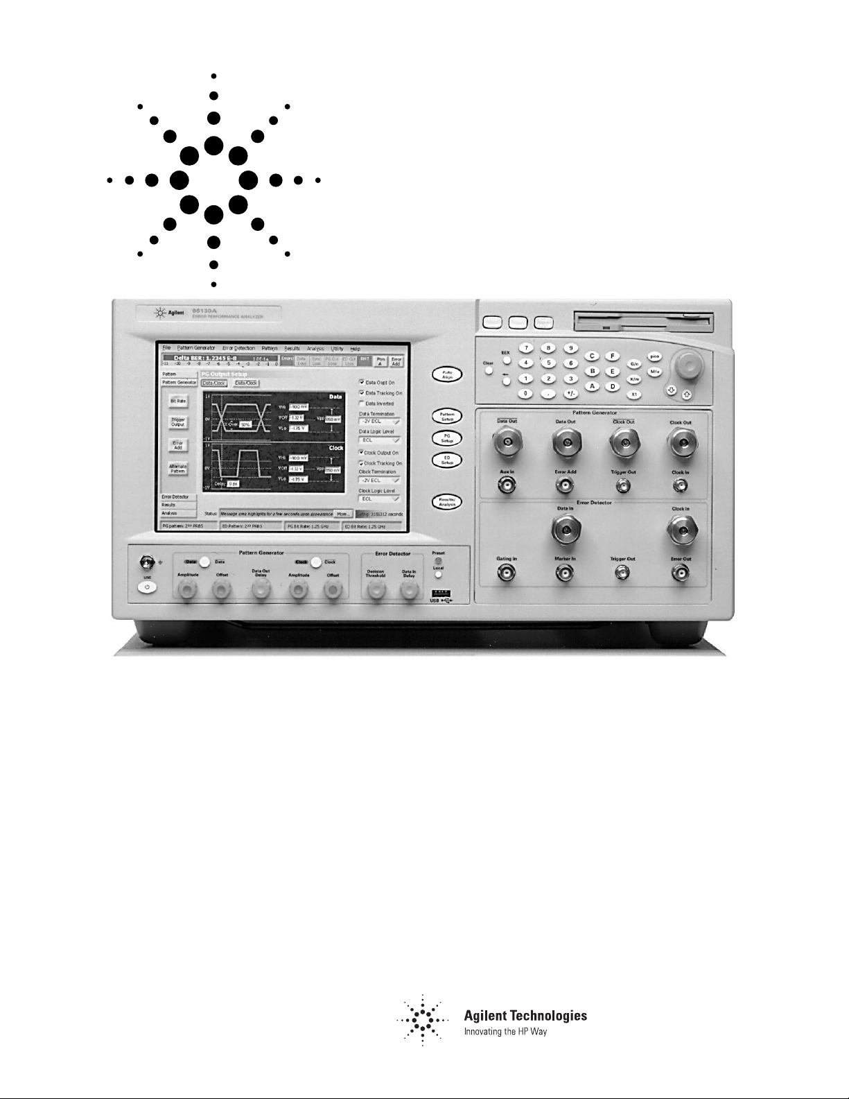
Agilent 86130A BitAlyzer
Error Performance
Analyzer
Technical Specifications
General Features
Internal Hard Disk
For local storage of user patterns and data
Removable Storage
MS-DOS
®
compatible 3.5” Superdrive (accepts 1.4 Mbyte
HD disks & 120 Mbyte SuperDisks
™
)
Data Entry
Touch-sensitive display, numeric keypad with up/ down
arrows, analogue feel position controls, or provided
USB keyboard and mouse if desired.
Display
Internal 8” (diagonal) backlit LCD touch-screen
Interfaces
GPIB (IEEE 488), LAN (“10 Base T” Ethernet) for
printing and file transfer, Parallel/Centronics printer
port, external VGA output.
On-line Help
Context-sensitive On-Line help is included. Operation,
programming and quick-start guides are also included
and supplied on MS-Windows
®
compatible CD-ROM.
Accessories Supplied
USB compatible keyboard; mouse; stylus; Quick Start
Manual on paper; Quick Start Card.
MS-Windows
®
compatible CD-ROM containing “PDF”
files of Operating, Quick-Start, and Programming guides.
Power Cord; 6x APC-3.5 connector savers (female to
female); 6x 50Ω APC-3.5 (male) terminations, 3x 1 metre
SMA (male to male) cables.
®

2
Pattern Generator
Pattern Generator Parameters
Operating Frequency
Operating Frequency
50 MHz to 3.6 GHz with external clock
50 MHz to 3.0 GHz with internal clock source
Internal Clock Source
Frequency Range
50 MHz to 3.0 GHz
Frequency Accuracy
±20 ppm
Test Patterns
2N-1 PRBS
2
31
-1, 223-1, 215-1, 210-1, 27-1
2
N
PRBS
2
23
, 215, 210, 2
7
Variable Mark Density
1/8, 1/4, 1/2, 3/4, 7/8
User Defined Patterns
Variable length patterns from 1 to 8 Mbits
Alternating Patterns
Change between two equal length user patterns, each up
to 4 Mbits long. Changeover is synchronous with the end
of a pattern, under the control of the front panel or the
Auxiliary Input.
Error Add
Single, continuously variable between 1x10
-2
and 1x10⁻⁹,
and user specified bursts of errors.
Pattern Editor
Fully flexible pattern editor included with “cut”, “copy” and
“paste” functions.
3
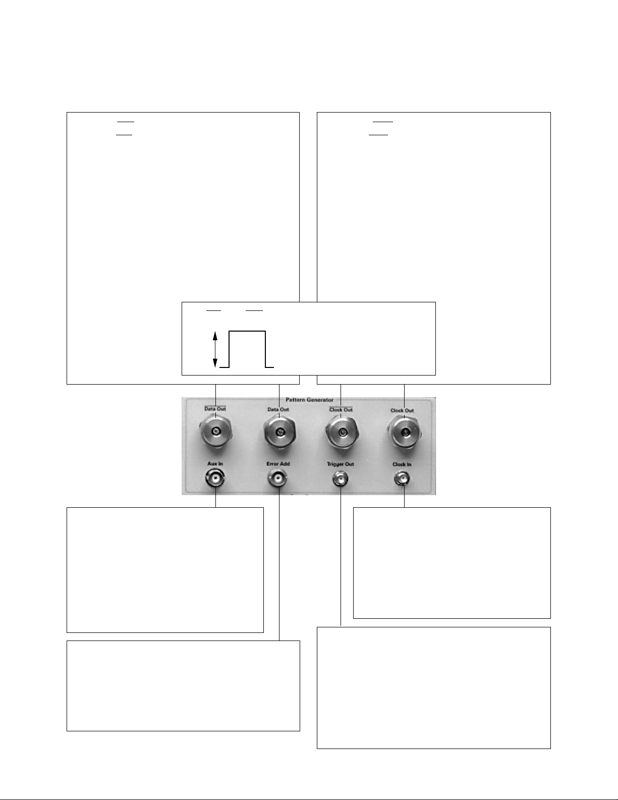
Pattern Generator
Input/Output Specifications
Data and Data Outputs
Data and Data outputs are independently settable
Format: NRZ
Polarity: Normal or Inverted
Amplitude: 0.5 to 2 V in 10 mV steps
Offset: See figure below. 10mV resolution.
Data Outputs On/Off: ‘Off’ goes to high impedance state
Supported Terminations:
0 V (LVTTL, SCFL, etc.), –2 V (ECL), +1.3 V (3.3 V PECL),
AC-coupled
Jitter (pk-pk): <20 ps, <12 ps typical
Transition Time (10–90%): <45 ps typical
Variable Crossover: Supported
Clock/ Data Delay Range: 0–1 bit period or 10 ns,
whichever is less. 1 ps resolution.
Interface: DC-coupled
50Ω reverse terminated,
APC-3.5 connector
Clock and Clock Outputs
Clock and Clock outputs are independently settable
Amplitude: 0.5 to 2 V in 10 mV steps
Offset: See figure below.
10mV resolution.
Clock Outputs On/Off: ‘Off’ goes to high impedance
state
Supported Terminations:
0 V (LVTTL, SCFL, etc.), –2 V (ECL), +1.3 V (3.3 V PECL),
AC-coupled
Transition Time (10–90%): <45 ps typical
Interface: DC-coupled 50Ω reverse terminated, APC-3.5
connector
Intrinsic Clock to data delay is constant at all frequencies.
Auxiliary Input
This has two functions.
1. Blanks the data outputs to allow the user to
create bursts of data
2. If in Alternating Pattern mode, used to
change between ‘A’ and ‘B’ patterns
Minimum pulse width: 64 clock periods
Interface: TTL compatible, 50Ω BNC female
connector
Clock Input
Allows connection of an external clock source
in order to extend the operating range of the
instrument. Recommended clock sources
Agilent 8648D and 83752A.
Frequency Range: 50 MHz to 3.6 GHz
Amplitude Range: +3 dBm to –3 dBm
Interface: SMA female 50Ω, DC coupled to 0 V
Error Add Input
This allows injection of single errors by an external pulse
generator into the transmitted test pattern synchronous
with the rising edge of the pulse
Minimum pulse width: 64 clock periods
Interface: TTL compatible, 50Ω BNC female connector
Trigger Output
Provides a pulse to trigger a communication analyzer
etc. It has two modes:
1. Divided Clock mode: pulses at 1/8th of the clock rate.
2. Pattern mode: pulse at a settable bit position within
the pattern.
Min.pulse width: (Pattern mode) 64 bits
Output levels: High –0.2 V, Low –0.9 V
Interface: 50Ω SMA female
Data/Data/Clock/Clock Amplitudes and Offsets
0.5 min
to
2V max
Termination:
Maximum High Level:
or
Minimum Low Level:
–2 V
0 V
–3 V
0 V
2.5 V
–3 V
+1.3 V
2.5 V
–3 V

4
Error Detector
Error Detector Parameters
Operating Frequency
50 MHz to 3.6 GHz.
Test Patterns
As specified for Pattern Generator
Auto-Align
Includes synchronizing, data polarity, clock/ data align,
clock invert, 0/1 threshold center.
Data In Delay
Manual Data In Delay/Auto Clock-Data Align
Threshold Setting
Manual set, Average DC level set, Auto 0/1 center
Synchronization
Manual, Automatic, Burst*, Capture*. Sync threshold
adjustable from 10
-1
to 10-9.
Results
Accumulated measurements may be run once, repetitively
or manual start/ stop.
Delta (instantaneous) BER always available.
Manual start/ stop
Time
Accumulate for periods from 1second to 100 days
Errors
Until at least 10/100/1000 errors
Bits
107 to 1015 bits
Results are logged periodically to the hard disk for later
export (in ‘CSV’ format) and analysis in a PC spreadsheet
program.
Result Displays
Results are displayed under the following headings.
Delta BER Results
Delta Error Ratio, Delta Error Count, Graph of BER vs Time
Accumulated Results
Bit Count, Error Ratio, Error Count, Errored One Count,
Errored Zero Count, Error Free Seconds, Errored Seconds,
Elapsed Accumulation Time, Sync Loss Seconds, Power
Loss Seconds, Graph vs Time
Eye Results
Eye Width, Eye Height, Eye Voltage Center value, Eye
Time Center value, Delta Error Ratio at Eye Center on
completion of Autoalign
Error Analysis*
Graphs of Burst Lengths, Error Free Intervals, Correlation
Analysis, Pattern Sensitivity Analysis, Block Analysis, Strip
Chart
Audible Error Indicator
Selectable to indicate Isolated Errors, Delta Error Ratio,
Errors above user-defined threshold. On/Off Volume Control.
Audible pitch changes, with higher pitch corresponding to
higher BER.
* Burst Mode, Capture Synch and Error Analysis coming later.

5
Error Detector
Input/Output Specifications
Data Input
Polarity: Normal or Inverted
Input Amplitude: 0.1 to 2 V
Threshold Range: +3 to –3 V
Threshold Resolution: 0.5 mV
Terminations: Via 50Ω to –2 V, 0 V, +1.3 V
Data Input Delay Range: 0–1 bit period, or 10 ns
whichever is less. 1 ps resolution
Interface: DC-coupled 50Ω, APC-3.5 female connector
Clock Input
Clock Input functions—switchable termination voltages,
input frequency measurement, clock invert.
Bit Rate: 50 MHz to 3.6 GHz
Data Sampling Clock Edge: Selectable Rising or
Falling
Amplitude: 0.5 to 2 V
Terminations: Via 50Ω to –2 V, 0 V, +1.3 V
Interface: DC-coupled 50Ω, APC-3.5 female
Gating Input
This is used to inhibit error counting
Minimum pulse width: 64 clock periods
Interface: TTL compatible, 50Ω BNC female
connector
Marker Input
Takes in reference marker signal to provide reference
for Error Correlation Analysis
Pulse width: 64 clock periods
Interface: TTL compatible, 50Ω BNC female
connector
Error Output
Provides a pulse if one or more errors have been
detected within the preceding 128 bit block.
Pulse Width: 64 bits
Output Levels: High +2.4 V, Low +0.4 V
Interface: DC-coupled, reverse terminated
50Ω BNC female connector
Trigger Output
Provides a pulse to trigger a communication analyzer etc.
It has two modes:
1. Divided Clock mode: pulses at 1/8th of the clock rate.
2. Pattern mode: pulse at a fixed bit position within the
pattern.
Pulse width (Pattern mode): 64 bits
Output levels: High –0.2 V, Low –0.9 V
Interface: 50Ω SMA female
6
External Parameters
Environmental
Warm-up time
30 minutes
Operating Temperature Range to specification
10 to 45°C
Humidity
15 to 95% at 45°C non-condensing
Electrical
Supply Voltage Parameters
90 V–250V AC, 50–60Hz
Power Consumption
<500W
EMC
EU EMC Directive (CE-Marked)
Support
Warranty
1 year
Calibration
2 year cycle, return to Agilent Technologies
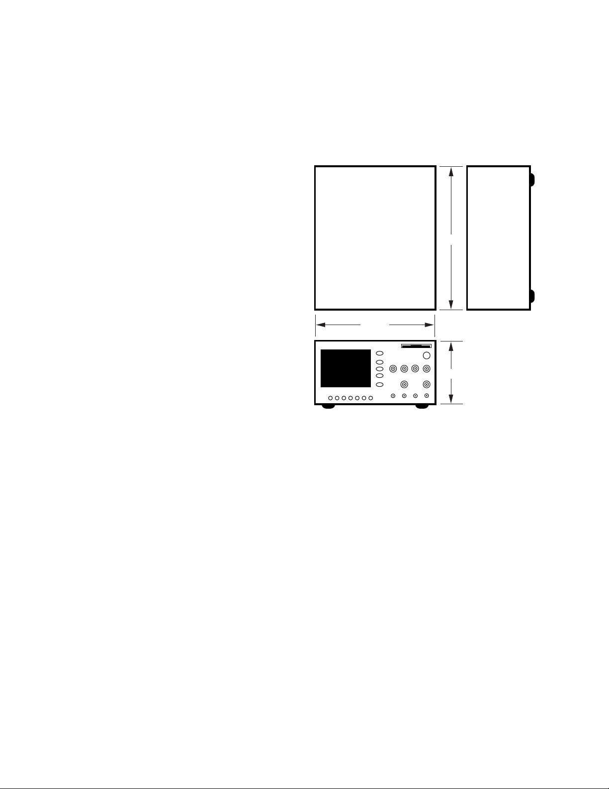
Physical
Dimensions
426 W x 215 H x 527 D mm approx (16.8” W x 8.5” H x
20.7” D approx)
Weight
20 kg (44 lbs)
527 mm
426 mm
215 mm

7
Ordering
Information
❑ 86130A BitAlyzer 3 Gbit/s BitAlyzer with basic error analysis features
(for 3.0 Gbit/s BER measurement and analysis with internal
clock source, 3.6 Gbit/s with external clock source)
❑ Option 100 2-D error mapping*
❑ Option 200 Error correction coding analysis*
❑ Option 300 Add 8648D 4.0 GHz external synthesized signal source
❑ Option 0B1 Hard copy programming manuals
❑ Option AX4 Mounting kit for 19” rack, without handles
❑ Option AXE Mounting kit for 19” rack, including front handles
Recommended Product Accessories
Torque Wrench:
❑ 8710-1765 For APC 3.5 connectors
Cable:
❑ 8120-4948 1m SMA cable
Blocking Capacitor:
❑ 11742A 45 MHz to 26.5 GHz, APC-3.5 mm
Bias Network:
❑ 11612A 45 MHz to 26.5 GHz, APC-3.5 mm
Attenuators:
❑ 8493C option 003 3 dB APC 3.5 pad
❑ 8493C option 006 6 dB APC 3.5 pad
❑ 8493C option 010 10 dB APC 3.5 pad
❑ 8493C option 020 20 dB APC 3.5 pad
Transition Time Convertors:
Used to slow the output waveform rise/fall times if desired. SMA male to SMA
female connectors.
❑ 15435A 150 ps output transition time
❑ 15432B 250 ps output transition time
❑ 15433B 500 ps output transition time
❑ 15434B 1000 ps output transition time
❑ 15438A 2000 ps output transition time
* Contact factory for availability
SuperDisk is a trademark of Imation Corp.
BitAlyzer is a registered trademark of SyntheSys Research Inc.
MS-DOS and MS-Windows are U.S. registered trademarks of Microsoft Corporation.

For more information about Agilent Technologies
test and measurement products, applications,
services, and for a current sales office listing,
visit our web site,
http://www.agilent.com/comms/lightwave
You can also contact one of the
following centers and ask for a test and
measurement sales representative.
United States:
Agilent Technologies
Test and Measurement Call Center
P.O. Box 4026
Englewood, CO 80155-4026
(tel) 1 800 452 4844
Canada:
Agilent Technologies Canada Inc.
5150 Spectrum Way
Mississauga, Ontario
L4W 5G1
(tel) 1 877 894 4414
Europe:
Agilent Technologies
Test & Measurement
European Marketing Organisation
P.O. Box 999
1180 AZ Amstelveen
The Netherlands
(tel) (31 20) 547 9999
Japan:
Agilent Technologies Japan Ltd.
Measurement Assistance Center
9-1, Takakura-Cho, Hachioji-Shi,
Tokyo 192-8510, Japan
(tel) (81) 426 56 7832
(fax) (81) 426 56 7840
Latin America:
Agilent Technologies
Latin American Region Headquarters
5200 Blue Lagoon Drive, Suite #950
Miami, Florida 33126, U.S.A.
(tel) (305) 267 4245
(fax) (305) 267 4286
Australia/New Zealand:
Agilent Technologies Australia Pty Ltd
347 Burwood Highway
Forest Hill, Victoria 3131, Australia
(tel) 1-800 629 485 (Australia)
(fax) (61 3) 9272 0749
(tel) 0 800 738 378 (New Zealand)
(fax) (64 4) 802 6881
Asia Pacific:
Agilent Technologies
24/F, Cityplaza One, 1111 King’s Road,
Taikoo Shing, Hong Kong
(tel) (852) 3197 7777
(fax) (852) 2506 9284
Technical data subject to change
Copyright © 2000
Agilent Technologies
Printed in U.S.A. 4/00
5968-8545E
 Loading...