


Installation Guide
Rack Mount Kits
For rack mounting HP 86120A/B/C instuments.

HP Part No. 5962-5907
Printed in USA
February 1996
First Edition
© Copyright Hewlett-Packard Company 1996
All Rights Reserved. Reproduction, adaptation, or translation without prior
written permission is prohibited, except as allowed under copyright laws.
Hewlett-Packard Company
Lightwave Operations
1400 Fountaingrove Parkway
Santa Rosa, CA 95403-1799, USA
(707) 577-1400
Notice.
The information contained in this document is subject to
change without notice. Companies, names, and data used in examples
herein are fictitious unless otherwise noted. Hewlett-Packard makes no
warranty of any kind with regard to this material, including but not limited to, the implied warranties of merchantability and fitness for a particular purpose. Hewlett-Packard shall not be liable for errors
contained herein or for incidental or consequential damages in connection with the furnishing, performance, or use of this material.
Restricted Rights Legend.
Use, duplication, or disclosure by the U.S.
Government is subject to restrictions as set forth in subparagraph (c)
(1) (ii) of the Rights in Technical Data and Computer Software clause
at DFARS 252.227-7013 for DOD agencies, and subparagraphs (c) (1)
and (c) (2) of the Commercial Computer Software Restricted Rights
clause at FAR 52.227-19 for other agencies.
2

Safety Symbols
The following safety symbols are used throughout this manual. Familiarize yourself with each of the symbols and its meaning before operating this instrument.
CAUTION The caution sign denotes a hazard to the instrument. It calls attention to a
procedure which, if not correctly performed or adhered to, could result in
damage to or destruction of the instrument. Do not proceed beyond a caution
sign until the indicated conditions are fully understood and met.
WARNING The warning sign denotes a life-threatening hazard. It calls attention
to a procedure which, if not correctly performed or adhered to, could
result in injury or loss of life. Do not proceed beyond a warning sign
until the indicated conditions are fully understood and met.
3

Introduction
Introduction
The installation instructions in this book apply to the following kits:
• Rack-mount kit, 86120-60030
• Rack-mount kit with handles, 86120-60031
• Rack-slide kit, 1494-0059
These kits mount 4.5-inch instruments into a rack with 482.6 mm (19 inch)
spacing. For a list of parts contained in the kits, refer to “Replacement Parts”
on page 17.
CAUTION When installing the rack-mount kits, the instrument’s cover must be
temporarily removed. Because this exposes the internal circuits to
electrostatic disharge, perform the procedure at a static-safe workstation.
Refer to “Electrostatic Discharge Information” on page 19.
5HTXLUHG#7RROV The following tools are needed to assemble the rack- mount kits. If a 7 mm nut
driver is unavailable, the needlenose pliers may be substituted.
#1 pozidrive screwdriver
#2 pozidrive screwdriver
4 mm hex key (included with kit)
7 mm nut driver (preferred) or needlenose pliers
5.5 mm nut driver (preferred) or needlenose pliers
T-6 TORX driver
T-10 TORX driver, right angle (included with kit)
T-15 TORX driver
For any assistance, contact your nearest Hewlett-Packard Sales and Service
Office. Refer to “Hewlett-Packard Sales and Service Offices” on page 21.
4

,QWURGXFWLRQ
&RQWHQWV
To rack mount the instrument 6
To install the rack-slide kit 15
Replacement Parts 17
Electrostatic Discharge Information 19
Hewlett-Packard Sales and Service Offices 21
5

To rack mount the instrument
To rack mount the instrument
Please observe the following. Circled numbers in this procedure refer
to items shown in figures. HP part numbers are listed in parenthesis.
You will find these part numbers listed on the bags that contain the
parts.
WARNING The opening of covers or removal of parts is likely to expose
dangerous voltages. Disconnect the instrument from all voltage
sources while it is being opened.
1. Disconnect the power cord from the instrument.
2. Place the instrument face down as illustrated in
Figure 1
.
3. Remove the eight screws (four per side) securing the front bumpers
➁
to the instrument.
4. Remove the two screws securing the handle, and remove the handle.
5. Use a 4 mm hex key (8710-1755) to loosen the four screws ➂ in the
rear feet to disengage the cover assembly ➀ from the instrument.
CAUTION Beneath the cover, located in the vicinity of the handle attachment screws, are
two finger springs that reduce electro-magnetic interference (EMI). These
springs can be damaged. To avoid damage, perform the following steps
carefully to remove the cover.
6. Located the side of the instrument opposite to where the handles
were attached. While applying pressure to this side, simultaneously
pull on the instrument foot that is located on the side where the
handle was attached.
This action relieves strain on the springs while removing the
cover.
6

7R#UDFN#PRXQW#WKH#LQVWUXPHQW
.
Figure 1. Preparing the cover assembly
7. Slide the instrument cover assembly toward the rear of the
instrument, and remove the cover from the instrument.
8. Remove the two screws ➃ that attach the rear feet to the cover
assembly, and remove the feet. These screws are located inside the
cover.
9. Remove the six screws that secure the two bottom tilt-stand feet,
and remove the feet. The screws are located inside the cover. Use
the T-10 right-angle TORX key included with the kit.
CAUTION Be careful to protect the instrument’s cable assemblies and components from
damage when you replace the cover assembly. Use key caution to avoid
damaging the EMI springs. If you damage an EMI spring, you can order a new
one using HP part number 8160-0656.
10.Slide the cover assembly back onto the instrument chassis while
applying pressure to the side of the cover that is opposite the handle
7

To rack mount the instrument
attachment points.
Gentle pressure ensures that the cover will not bind against the
EMI springs. Make sure that the seam in the cover is located on
the bottom of the instrument.
CAUTION Make sure that the instrument’s cover properly engages the gasket in the
instrument’s front frame.
11.Onto each of the four socket-head cap screws (0515-0049), place a
split-lock washer (2190-0587) and a flat washer (3050-0894).
12.Use these screws to temporarily attach the instrument’s cover.
13.Locate the rack-mount kit’s rear support ➁ (5002-0634) and rear
frame ➀ (5021-5804) as illustrated in Figure 2.
The text “METRIC” on the frame and the two adjacent holes
illustrated in the figure identify the top sides. This orientation
ensures that the top of the frame and the top of the rear support
are joined correctly.
Figure 2. Assembling the rack’s rear frame
14.Position the rear support’s studs into the corresponding top row of
holes in the rear frame.
15.Slightly squeeze the rear support until the bottom row of studs clears
8

7R#UDFN#PRXQW#WKH#LQVWUXPHQW
the rear frame and insert into the bottom row of holes. Fasten with
eight nuts ➂ (0535-0031). Alternately tighten each nut to the
recommended torque of 6 inch-pounds.
16.Attach the four side struts (5021-5837) to the rack’s rear frame using
eight screws ➀ (0515-1331). See Figure 3.
Figure 3. Attaching the side struts
17.Connect the two front mounting brackets ➀ (5002-0633) to the
instrument’s front frame using four pan-head screws ➂ (0515-1079).
See Figure 4. Tighten each screw to a torque of 6 inch-pounds.
18.Locate the kit’s front frame (5021-8403). Look into the frame as if
you were looking into the front of an instrument. Find the two vent
holes which are about half an inch long and a quarter of an inch high.
When the frame is installed, these holes must be oriented along the
bottom of the instrument.
9

To rack mount the instrument
Figure 4. Attaching the mounting brackets
19.Slide the kit’s front frame ➀ over the rear of the instrument until it is
over the instrument’s front frame. See Figure 5.
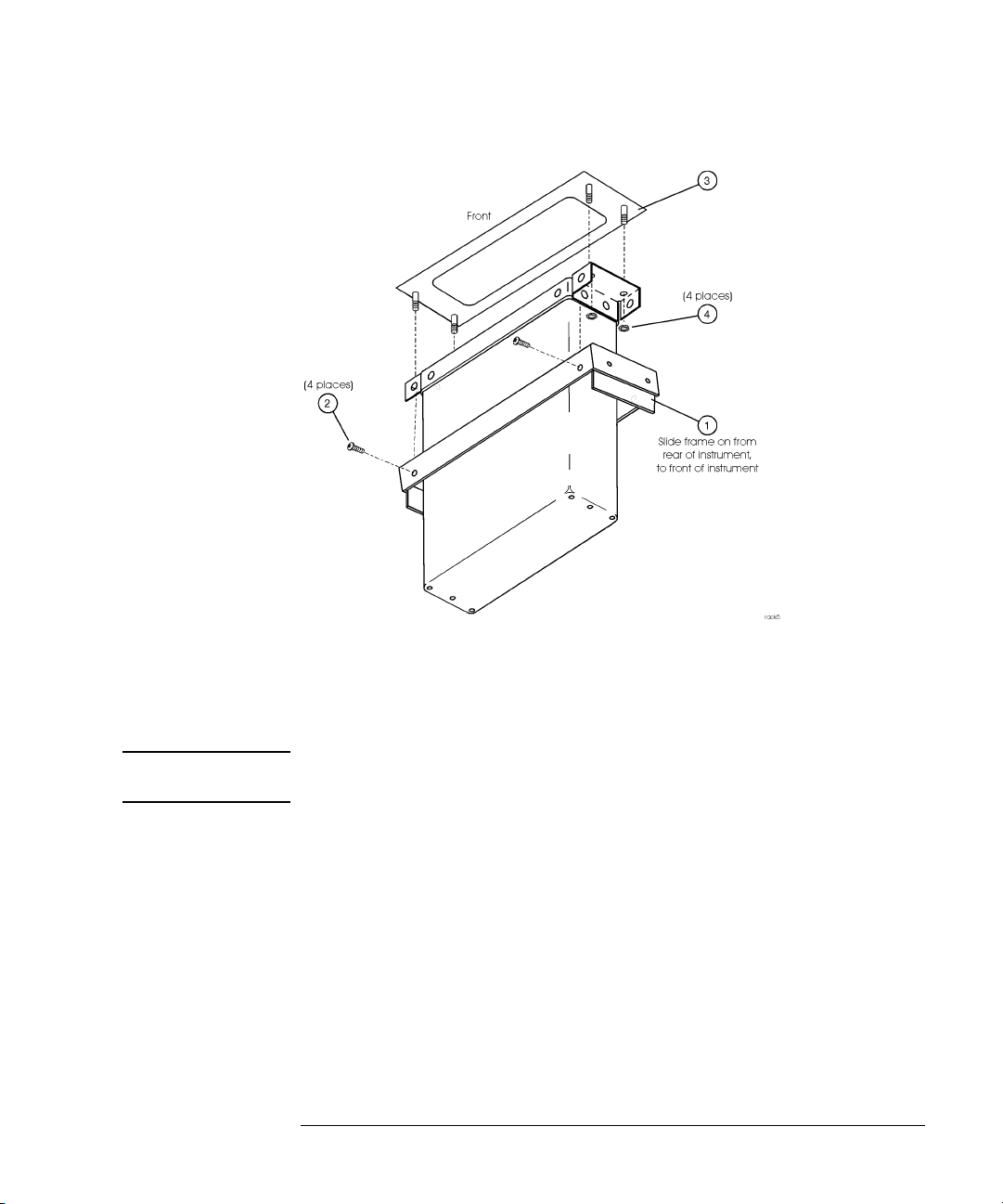
20.Attach the frame to the front brackets using four flat-head screws ➁
(0515-1234).
21.Place the dress panel ➂ (5002-0640) over the instrument’s front
panel. Secure with four nuts ➃ (0535-0082) tightened to a torque of
6 inch-pounds.
do not
If you
have a 7 mm nut driver, use the spring clips rather
than the six nuts. Apply the spring clips to the dress panel studs
using needlenose pliers.
CAUTION Do not overtorque the nuts.
10
7R#UDFN#PRXQW#WKH#LQVWUXPHQW
Figure 5. Attaching the front
22.Place the instrument on its front frame.
CAUTION Avoid damaging the instrument’s front panel and input connector by placing it
onto a surface protected by cloth.
23.Remove the four socket-head cap screws that secure the
instrument’s cover. Do not remove the cover. You attached these
screws in step 12.
24.Place the rack-mount kit frame onto the instrument as shown in
Figure 6.
11

To rack mount the instrument
Figure 6. Attaching the rack frame
25.Secure the four side struts to the front frame using eight screws ➀
(0515-1331). Torque the screws to 12 inch-pounds.
26.Use the four socket-head cap screws ➀ removed in step 23 to secure
the instrument’s cover as shown in Figure 7.
12

7R#UDFN#PRXQW#WKH#LQVWUXPHQW
Figure 7. Securing the frame
27.Place the instrument in its operating position. See Figure 8.
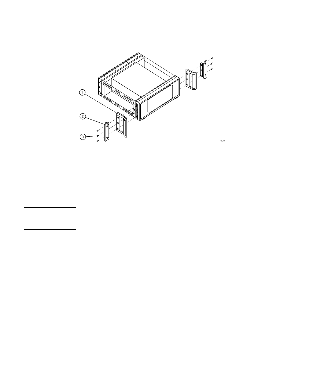
28.If you are installing the rack-mount kit with handles (5062-3983),
mount the handles ➀ and rack flanges ➁ to the rack frame using six
pan-head screws ➂. Tighten each screw to a torque of 12 inchpounds.
13
To rack mount the instrument
Figure 8. Attaching the flanges and handles
29.If your installing the rack-mount kit without handles (5062-3977),
mount rack flanges ➁ directly to the rack frame using six pan-head
screws ➂. Tighten each screw to a torque of 12 inch-pounds.
30.The instrument is now ready to mount into the system rack.
WARNING If an instrument handle is damaged, it should be replaced immediately.
Damaged handles can break while the instrument is being moved or
lifted. This may cause damage to the instrument or personal injury.
14

7R #LQVWDOO#WKH#UDFN0VOLGH#NLW
To install the rack-slide kit
1. Install the rack-mount kit as described in “To rack mount the
instrument” on page 6.
2. Expand each rack slide to its full length.
Note that Figure 9 does not show the rack slide extended to its
full length.
Figure 9. Installing rack slides
3. Separate the inner slide member ➀ from the outer slide member ➁
by pressing the release button located on the inner slide member.
15

To install the rack-slide kit
4. Pull the inner slide member out of the assembly.
5. Attach an inner slide member to each side of the rack-mount frame
using four (two per side) M5 X 0.8 X 14 mm pan-head screws ➂.
6. Insert two unistrut nuts ➃ in each of the four vertical columns of the
systems rack.
7. Compress each outer-slide member to its shortest length, revealing
the holes ➄ for screws ➅. If necessary, press the release button ➆.
8. Attach an outer slide member to each side of the systems rack, using
two M4 X 0.7 X 12 mm flat-head screws ➅ in the front and two M4 X
0.7 X 12 mm pan-head screws ➇ in the rear.
9. Place the instrument into the rack by sliding the inner slide members
into the outer slide members. Use the release buttons, located on the
slides, to enable complete compression of the slides.
10.To prevent the rack slides from accidentally opening, use screws to
secure the rack frame to the system cabinet.
16

Replacement Parts
Table 1. Rack-Mount Kits (86120-60030 and 86120-60031)
5HSODFHPHQW#3DUWV
HP Part
Number
5062-3983 1 Front-handle kit (with handles). Supplied with 86120-60031
5062-3977 1 Front-handle kit (without handles). Supplied with 86120-
8710-1755 1 Hex Key, 4mm
8710-1657 1 T10 right-angle TORX key
5002-0640 1 Dress Panel
5021-8403 1 Front Frame
5002-0633 2 Front Bracket
5002-0634 1 Rear Support
5021-5804 1 Rear Frame
5021-5837 4 Side Strut
0535-0031 8 Nut M3 X 0.5mm
0535-0082 4 Nut M4 X 0.7mm
2190-0587 4 Lock Washer M5.0 ID
Qty Description
kit.
60030 kit.
3050-0894 4 Flat Washer M5.0 ID
0510-1148 6 Push-On Retainer Clips
0515-0049 4 Screw, Socket-Head M5 X 0.8 X 12 mm-LG
0515-1079 4 Screw, Mach M3 X 0.5 8 mm-LG PAN-HD
0515-1234 4 Screw, Mach M3.5 X 8 mm-LG FLAT-HD
0515-1331 16 Screw, Mach M4 X 0.7 6 mm-LG FLT-HD
17

Replacement Parts
Table 2. Rack Slide Kit (HP part number 1494-0059)
HP Part
Number
— 2 Slides (not sold separately)
0515-0949 4 Screw, Mach M5 X 0.8 14 mm-LG PAN-HD
0515-1013 4 Screw, Mach M5 X 0.7 12 mm-LG FLAT-HD
0515-0909 4 Screw, Mach M4 X 0.7 12 mm-LG PAN-HD
0535-0080 8 Unistrut Nut M4 X 0.7
Qty Description
18
(OHFWURVWDWLF#'LVFKDUJH#,QIRUPDWLRQ
Electrostatic Discharge Information
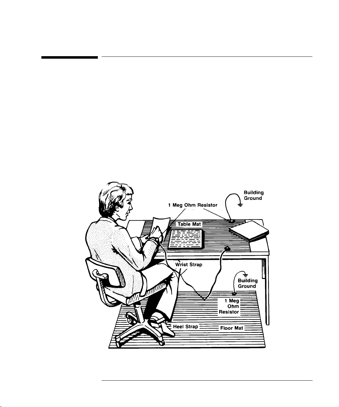
Electrostatic di schar ge (ESD) can dama ge or des troy electro nic compone nts.
All work on electroni c ass embl ie s shou ld be performed at a static-safe work
station. The following figure sh ows an example of a static-safe wo rk station
using two types of ESD protection:
• Conductive table-mat and wrist-strap combination.
• Conductive floor-mat and heel-strap combination.
19

Electrostatic Discharge Information
Both types, when used together, provide a significant level of ESD
protection . Of the two, onl y the table-mat and wrist- strap combi nation
provides adequate ESD protection when used alone.
To ensure user safety, the static-safe accessories must provide at least 1 MΩ
of isolation from ground. Refer to Table 3 on page 20 for information on
ordering static-safe accessories.
WARNING These techniques for a static-safe work station should not be used
when working on circuitry with a voltage potential greater than 500
volts.
The following suggestions may help reduce ES D damage t hat occ urs duri ng
testing and servicing operations.
• Personnel should be grounded with a resistor-isolated wrist strap before removing any assembly from the unit.
• Be sure all instruments are properly earth-grounded to prevent a
buildup of static charge.
Table 3 on page 20 lists static-safe accessories that can be obtained from
Hewlett-Packard using the HP part numbers shown.
Table 3. Static-Safe Accessories
HP Part
Number
9300-0797
9300-0980 Wrist-strap cord 1.5 m (5 ft)
9300-1383 Wrist-strap, color black, stainless steel, withoutcord, has four adjustable
9300-1169 ESD heel-strap (reusable 6 to 12 months).
20
Set includes: 3M static control mat 0.6 m
ft) ground wire. (The wrist-strap andwrist-strap cord are not included. They
must be ordered separately.)
links and a 7 mm post-type connection.
Description
×
1.2 m (2 ft× 4 ft) and 4.6 cm (15

U.S. FIELD OPERATIONS
+HZOHWW03DFNDUG#6DOHV#DQG#6HUYLFH#2IILFHV
Hewlett-Packard Sales and Service Offices
Hewlett-Packard Sales and Service Offices (1 of 2)
Headquarters
Hewlett-Packard Company
19320 Pruneridge Avenue
Cupertino, CA 95014 U.S.A.
(800) 752-0900
Colorado
Hewlett-Packard Company
24 Inverness Place, East
Englewood, CO 80112
(303) 649-5000
New Jersey
Hewlett-Packard Company
120 West Century Road
Paramus, NJ 07653
(201) 586-5400
EUROPEAN FIELD OPERATIONS
Headquarters
Hewlett-Packard S.A.
150, Route du Nant-d’Avril
1217 Meyrin 2/Geneva Switzerland
(41 22) 780.8111
Great Britain
Hewlett-Packard Ltd.
Eskdale Road, Winnersh Triangle
Wokingham, Berkshire RG11 5DZ
California, Northern
Hewlett-Packard Company
301 East Evelyn
Mountain View, CA 94041
(415) 694-2000
Georgia
Hewlett-Packard Company
2000 South Park Place
Atlanta, GA 30339
(404) 955-1500
Texas
Hewlett-Packard Company
930 East Campbell Road
Richardson, TX 75081
(214) 231-6101
France
Hewlett-Packard France
1 Avenue Du Canada
Zone D’Activite De Courtaboeuf
F-91947 Les Ulis Cedex France
(33 1) 69 82 60 60
California, Southern
Hewlett-Packard Company
1421 South Manhatten Ave.
Fullerton, CA 92631
(714) 999-6700
Illinois
Hewlett-Packard Company
5201 Tollview Drive
Rolling Meadows, IL 60008
(708) 342-2000
Germany
Hewlett-Packard GmbH
Hewlett-Packard Strasse
61352 Bad Homburg Germany
(+49 6172) 16-0
21

Hewlett-Packard Sales and Service Offices
Hewlett-Packard Sales and Service Offices (2 of 2)
INTERCON FIELD OPERATIONS
Headquarters
Hewlett-Packard Company
3495 Deer Creek Rd.
Palo Alto, California 94304-1316
(415) 857-5027
China
China Hewlett-Packard Company
38 Bei San Huan X1 Road
Shuang Yu Shu
Hai Dian District
Beijing, China
(86 1) 256-6888
Taiwan
Hewlett-Packard Taiwan
8th Floor, H-P Building
337 Fu Hsing North Road
Taipei, Taiwan
(886 2) 712-0404
Australia
Hewlett-Packard Australia Ltd.
31-41 Joseph Street
Blackburn, Victoria 3130
(61 3) 895-2895
Japan
Yokogawa-Hewlett-Packard Ltd.
1-27-15 Yabe, Sagamihara
Kanagawa 229, Japan
(81 427) 59-1311
Canada
Hewlett-Packard Ltd.
17500 South Service Road
Trans-Canada Highway
Kirkland, Quebec H9J 2X8
Canada
(514) 697-4232
Singapore
Hewlett-Packard Singapore Ltd.
Pte. Ltd.
Alexandra P.O. Box 87
Singapore 9115
(65) 271-9444
22
 Loading...