

Page 1

HP86120C
マルチ・ウェーブレングス・
メータ
ユーザーズ・ガイド
Page 2

原 典
本書は “HP 86120C Multi-Wavelength Meter User’s Guide” (Part No. 86120-90018) (Printed in U.S.A.,
September 1998) の 1 〜 2 章、および 6 〜 7 章を翻訳したものです。
詳細は上記の最新マニュアルを参照してください。
ご 注 意
本書に記載した内容は、予告なしに変更することがあります。
•
当社は、お客様の誤った操作に起因する損害については、責任を負いかねますのでご了承くだ
•
さい。
当社では、本書に関して特殊目的に対する適合性、市場性などについては、一切の保証をいた
•
しかねます。
また、備品、パフォーマンス等に関連した損傷についても保証いたしかねます。
当社提供外のソフトウェアの使用や信頼性についての責任は負いかねます。
•
本書の内容の一部または全部を、無断でコピーしたり、他のプログラム言語に翻訳することは
•
法律で禁止されています。
本製品パッケージとして提供した本マニュアル、フレキシブル・ディスクまたはテープ・カー
•
トリッジは本製品用だけにお使いください。プログラムをコピーする場合はバックアップ用だ
けにしてください。プログラムをそのままの形で、あるいは変更を加えて第三者に販売するこ
とは固く禁じられています。
日本ヒューレット・パッカード株式会社
許可なく複製、翻案または翻訳することを禁止します。
Copyright ©Hewlett-PackardCompany1998
Copyright ©Hewlett-PackardJapan,Ltd.1999
Allrightsreserved.Reproduction,adaptation,ortranslationwithout
priorwrittenpermissionisprohibited.
Page 3

納入後の保証について
★ 保証の期間は、ご購入時に当社よりお出しした見積書に記載された期間とします。
保証サービスは、当社の定める休日を除く月曜日から金曜日までの、午前8時45分から午後
5時 30分の範囲で無料で行います。当社で定めたシステム製品については出張修理を行い、
その他の製品については当社へご返却いただいた上での引取り修理となります。
当社が定める地域以外における出張修理対象製品の修理は、保証期間中においても技術者派
遣費が有料となります。
★ ソフトウェア製品の保証は上記にかかわらず、下記に定める範囲とさせていただきます。
• ソフトウェア製品及びマニュアルは当社が供給した媒体物の破損、資料の落丁およびプロ
グラム・インストラクションが実行できない場合のみ保証いたします。
• バグ及び前記以外の問題の解決は、別に締結するソフトウェア・サポート契約に基づいて
実施されます。
★ 次のような場合には、保証期間内でも修理が有料となります。
• 取扱説明書等に記載されている保証対象外部品の故障の場合。
• 当社が供給していないソフトウェア、ハードウェア、または補用品の使用による故障の場
合。
• お客様の不適当または不十分な保守による故障の場合。
• 当社が認めていない改造、酷使、誤使用または誤操作による故障の場合。
• 納入後の移設が不適切であったための故障または損傷の場合。
• 指定外の電源(電圧、周波数)使用または電源の異常による故障の場合。
• 当社が定めた設置場所基準に適合しない場所での使用、および設置場所の不適当な保守に
よる故障の場合。
• 火災、地震、風水害、落雷、騒動、暴動、戦争行為、放射能汚染、およびその他天災地変
等の不可抗力的事故による故障の場合。
★ 当社で取扱う製品は、ご需要先の特定目的に関する整合性の保証はいたしかねます。また、そ
こから生ずる直接的、間接的損害に対しても責任を負いかねます。
★ 当社で取扱う製品は、ご需要先の特定目的に関する整合性の保証はいたしかねます。また、そ
こから生ずる直接的、間接的損害に対しても責任を負いかねます。
★ 当社で取扱う製品を組込みあるいは転売される場合は、最終需要先における直接的、間接的
損害に対しては責任を負いかねます。
★ 製品の保守、修理用部品の供給期間は、その製品の製造中止後最低5年間とさせていただき
ます。
本製品の修理については取扱説明書に記載されている最寄りの事業所へお問合わせください。
Page 4

ユーザーズ・ガイド
HP86120C
マルチ・ウェーブレングス・メータ
Page 5

© Copyright Hewlett-Packard
Company 1998
All Rights Reserved. Reproduction, adaptation, or translation without prior written
permission is prohibited,
except as allowed under copyright laws.
HP Part No. 86120-90019
Printed in USA
1999年1月
Hewlett-Packard Company
Lightwave Operations
1400 Fountaingrove Parkway
Santa Rosa, CA 95403-1799,
USA
(707) 577-1400
Notice.
The information contained in
this document is subject to
change without notice. Companies, names, and data used
in examples herein are fictitious unless otherwise noted.
Hewlett-Packard makes no
warranty of any kind with
regard to this material, including but not limited to, the
implied warranties of merchantability and fitness for a
particular purpose. HewlettPackard shall not be liable for
errors contained herein or for
incidental or consequential
damages in connection with
the furnishing, performance,
or use of this material.
Restricted Rights Legend.
Use, duplication, or disclosure by the U.S. Government
is subject to restrictions as set
forth in subparagraph (c) (1)
(ii) of the Rights in Technical
Data and Computer Software
clause at DFARS 252.2277013 for DOD agencies, and
subparagraphs (c) (1) and (c)
(2) of the Commercial Computer Software Restricted
Rights clause at FAR 52.22719 for other agencies.
Warranty.
This Hewlett-Packard instrument product is warranted
against defects in material and
workmanship for a period of
one year from date of shipment. During the warranty
period, Hewlett-Packard Company will, at its option, either
repair or replace products
which prove to be defective.
For warranty service or repair,
this product must be returned
to a service facility designated
by Hewlett-Packard. Buyer
shall prepay shipping charges
to Hewlett-Packard and
Hewlett-Packard shall pay
shipping charges to return the
product to Buyer. However,
Buyer shall pay all shipping
charges, duties, and taxes for
products returned to HewlettPackard from another country.
Hewlett-Packard warrants
that its software and firmware
designated by Hewlett-Packard for use with an instrument
will execute its programming
instructions when properly
installed on that instrument.
Hewlett-Packard does not
warrant that the operation of
the instrument, or software,
or firmware will be uninterrupted or error-free.
Limitation of Warranty.
The foregoing warranty shall
not apply to defects resulting
from improper or inadequate
maintenance by Buyer, Buyersupplied software or interfacing, unauthorized modification
or misuse, operation outside
of the environmental specifications for the product, or
improper site preparation or
maintenance.
No other warranty is
expressed or implied.
Hewlett-Packard specifically
disclaims the implied warranties of merchantability and fitness for a particular purpose.
Exclusive Remedies.
The remedies provided herein
are buyer's sole and exclusive
remedies. Hewlett-Packard
shall not be liable for any
direct, indirect, special, incidental, or consequential damages, whether based on
contract, tort, or any other
legal theory.
安全用記号
注意
注意記号は、危険であること
を示しています。この記号の
ある箇所に記した手順や行為
などを、正しく実行しなかっ
たり守らなかった場合には、
本製品の一部またはすべてに
損傷を与えたり、破壊したり
するおそれがあります。指示
されている条件を完全に理解
し、この条件に対応できるま
で、注意記号を無視して先に
進まないでください。
警告
警告記号は、危険であること
を示しています。この記号の
ある箇所に記した手順や行為
などは、正しく実行しなかっ
たり、守らなかったりすると
たいへん危険です。指示され
ている条件を完全に理解し、
この条件に対応できるまで、
警告記号を無視して先に進ま
ないでください。
取扱説明書マーク。取
扱説明書を参照する
必要のある箇所には、
製品のパネルにこの
マークが印刷してあ
ります。
レーザ放射マーク。
レーザ出力のある製
品のパネルにこの
マークが印刷されて
います。
交流マークは、電源モ
ジュール入力電力に
必要な性質を示すた
めに使用されます。
|ON記号は、測定器
の電源スイッチの位
置を示すために使用
されます。
❍OFF記号は、測定
器の電源スイッチの
位置を示すために使
用されます。
CEマークは、ヨーロッ
パ共同体の登録商標
です。
CSAマークは、カナダ
標準協会の登録商標
です。
C-Tickマークは、
Australia n S pectrum
Management Agency の
登録商標です。
このテキストは、測定
ISM1-A
器がISM ( Industrial
Scientific and Medical)
Group1ClassA製品で
あることを示してい
ます。
ii
Page 6

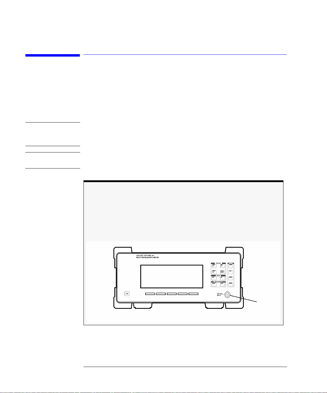
本器の概要
本器の概要
HP86120Cマルチウェーブ・メータは、波長レンジ1270〜1650nmレーザ光の波長お
よび光電力を測定します。本器は複数のレーザ線を同時に測定できるため、波長分
割多重(WDM)システムやファブリペロー・レーザ多重線の特性評価が可能です。
注記
前面パネルのOPTICALINPUTコネクタには、単一モード入力ファイバが用いら
れています。
注意 オプション022搭載の測定器の場合は、前面パネルの
ル物理接触インタフェースになります。
レーザ線の特性評価
本器は、次のようなパラメータ測定に力を発揮します。
最大200本のレーザ線の同時測定
•
波長と電力
•
平均波長
•
総光電力
•
レーザ線分離
•
レーザ・ドリフト(波長と電力)
•
SN比
•
ファブリペロー・レーザ
•
OPTICAL INPUT
コネクタはアング
iii
Page 7

本器の概要
これらの測定が可能なのに加え、従来のアナログ・メータに似た「パワー・バー」
が、電力の変化を表示します。次の図は、パワー・バーを含む本器のディスプレイ
表示例です。
注意 本器の入力回路は、総入力電力レベルが +18dBm を超えると損傷することがありま
す。回路の損傷を避けるため、仕様の入力レベルを超えないでください。
測定結果の印刷
本器裏面パネルの
をハードコピーできます。
PARALLEL PRINTER PORT
にプリンタを接続することにより、測定結果
本器のプログラミングにより自動測定
本器では、HP-IBプログラミング・コマンドの使用が可能です。これらのコマンドに
より自動測定を実行し、生産ラインや遠隔サイトで本器を使用できます。本器のプ
ログラミングについては、第3章と第4章で詳細に説明しています。
真空または標準大気での測定をシミュレート
すべての測定は普通の空気中で行ないますが、真空中または「標準大気」における
波長を正確に示すよう、測定値は空気分散に対し補正されています。このような測
定を正確に行なうため、必ず標高値を入力しなければなりません。標高の入力につ
いては、第1章「使用準備」を参照してください。
iv
Page 8

本器の概要
ユーザが決める測定確度
光ファイバ・コネクタは、汚れや破損のあるケーブルやアクセサリに接続する
と、簡単に損傷します。これは本器の前面パネルINPUTコネクタも例外ではあ
りません。クリーニングや取り扱いの方法を間違えると、高額の修理、ケーブ
ルの破損、不正確な測定のおそれがあります。
本器に光ファイバ・ケーブルを接続する前に、2-39頁「正確な測定を行うため
の接続部分の清掃」をよくお読みください。
v
Page 9
安全性に関する一般事項
安全性に関する一般事項
この製品はIECPublication1010,SafetyRequirementsforElectronicMeasuringApparatus
に準拠した設計・テストがなされ、安全な状態で出荷されています。また本器を安
全に操作し、安全な状態に保つために、マニュアルで示した事項や警告がユーザに
よって守られなければなりません。
レーザ・クラス:本製品はFDALaserClassI(IECLaserClass1)のレーザを含みます。
警告 本器を仕様通りに使用しないとき、本装置による保護が不完全となることがありま
す。本器は、正常な(すべての保護装備が損なわれないような)状況でのみ使用してく
ださい。
警告 本器内部には、操作者が修理可能な箇所はありません。本器の修理は、資格を持っ
た担当者に依頼してください。感電を防ぐため、カバーを取り外さないでください。
レーザ出力開口部はありません。
HP86120Cには出力レーザ用の開口部はありませんが、前面パネルの
コネクタから1nw以下の光が流出します。安全性を保つために操作者が保
INPUT
守を行ったり、予防措置を講じる必要はありません。本器の制御、調整、また
は操作によって、人体に有害な放射線に曝されることはありません。
vi
OPTICAL
Input
コネクタ
Page 10

目次
本器の概要 iii
安全性に関する一般事項vi
1
使用準備
ステップ 1.受領時の点検 1-4
ステップ 2.ヒューズの点検 1-6
ステップ 3.電源コードの接続 1-7
ステップ 4.プリンタの接続 1-8
ステップ 5.本器の電源オン 1-9
ステップ 6.標高値の入力 1-10
ステップ 7.波長媒体の選択 1-11
ステップ 8.波長制限のオフ 1-12
修理のための返却 1-13
2
測定の実施
波長と電力の測定 2-3
単位と測定速度の変更 2-12
レーザ線ピークの定義 2-15
レーザ分離の測定 2-18
レーザ・ドリフトの測定 2-21
SN 比の測定 2-24
アベレージングによる SN 比の測定 2-28
ファブリペロー (FP)レーザの測定 2-30
変調レーザの測定 2-33
10dBm を超える総電力の測定 2-35
測定の校正 2-36
測定結果の印刷 2-38
正確な測定を行うための接続部分の清掃 2-39
3 Programming
(本章は英文です)
Addressing and Initializing the Instrument 3-3
Making Measurements 3-5
Monitoring the Instrument 3-16
Reviewing SCPI Syntax Rules 3-23
Example Programs 3-29
Lists of Commands 3-43
目次
-1
Page 11

目次
4 Programming Commands
(本章は英文です)
Common Commands 4-3
Measurement Instructions 4-14
CALCulate1 Subsystem 4-23
CALCulate2 Subsystem 4-28
CALCulate3 Subsystem 4-40
CONFigure Measurement Instruction 4-70
DISPlay Subsystem 4-71
FETCh Measurement Instruction 4-75
HCOPy Subsystem 4-76
MEASure Measurement Instruction 4-77
READ Measurement Instruction 4-78
SENSe Subsystem 4-79
STATus Subsystem 4-86
SYSTem Subsystem 4-93
TRIGger Subsystem 4-99
UNIT Subsystem 4-103
5 Performance Tests
(本章は英文です)
Test 1. Absolute Wavelength Accuracy 5-3
Test 2. Sensitivity 5-4
Test 3. Polarization Dependence 5-5
Test 4. Optical Input Return Loss 5-6
Test 5. Amplitude Accuracy and Linearity 5-9
6
仕様と規制
用語の定義 6-3
本器の仕様―NORMAL 更新モード 6-5
仕様− FAST 更新モード 6-8
動作仕様 6-11
規制への対応 6-12
7
リファレンス
本器のプリセット・ステート 7-2
メニュー・マップ 7-4
エラー・メッセージ 7-11
前面パネル光ファイバ・アダプタ 7-17
目次
-2
Page 12

電源コード 7-18
HP セールス / サービス・オフィス 7-19
目次
目次
-3
Page 13

目次
目次
-4
Page 14

1
ステップ1.受領時の点検 1-4
ステップ2.ヒューズの点検 1-6
ステップ3.電源コードの接続 1-7
ステップ4.プリンタの接続 1-8
ステップ5.本器の電源オン 1-9
ステップ6.標高値の入力 1-10
ステップ7.波長媒体の選択 1-11
ステップ8.波長制限のオフ 1-12
修理のための返却 1-13
使用準備
Page 15

使用準備
使用準備
使用準備
本章では、本器のインストール方法を説明します。これらのインストール手順は、10
〜20分あれば終了します。本章の手順を終えた後、第2章「測定の実施」へ進んでく
ださい。
周囲温度などの動作条件については、第6章「仕様と規制」を参照してください。
キャビネットの汚れを落とす場合、湿らせた布以外は使用しないでください。
警告 感電事故を防ぐため、清掃は、本器を主電源から切り離してから行ってください。乾
いた布またはわずかに水を湿らせた布を用い、外部ケースの各部位を清掃してくだ
さい。内部の清掃は行わないでください。
警告 本器は安全クラス1(電源コード内に感電防止用アース導線を持つ)の機器です。電源
プラグは、感電防止用アース接点を持つコンセントにだけ差し込んでください。装
置内外の感電防止用アース導線が断絶するとたいへん危険です。故意の断線は禁じ
られています。
注意 本器は、オートレンジ電源ファブリペロー入力を使用しています。供給電圧は、必
ず仕様レンジ内でなければなりません。
注意 通気要件。本器をキャビネット内に設置する場合は、必ず通気を確保してください。
周囲温度(キャビネット外)は、本器の最高動作温度より、キャビネット内で放散され
る100ワットにつき4℃低くなくてはなりません。キャビネット内で放散される総電
力が800ワットを超えるときは、強制排気が必要です。
注意 本器は、IEC規格1010および664にそれぞれ対応する、設置カテゴリIIならびに汚染
程度2に適合するように設計されています。
1-2
Page 16

使用準備
使用準備
注意 前面パネルのLINEスイッチは、本器の主回路と主電源を、EMCフィルタの後、その
他の部分の前で切り離します。
注意 本器を設置する場合には、ON/OFFスイッチが操作者にとって分かりやすく、しか
も簡単に手の届く範囲に来るように設置してください。ON/OFFスイッチまたは
着脱式電源コードが本器の断路器の役割を果たし、主回路と主電源を、本器の他
の部分の前で切断します。別の方法として、外部に設置したスイッチやサーキッ
ト・ブレーカ(操作者にとって分かりやすく、しかも簡単に手の届く範囲に来るよ
うに設置)を断路器として使用することも可能です。
注意 本器を設置する場合は、付属の筐体保護に従って設置してください。本器は、浸水
を防ぐことはできません。本器は、筐体内の人体に危険を及ぼす部分に指を触れる
ことがないように保護されています。
ユーザが決める測定確度
光ファイバ・コネクタは、汚れや破損のあるケーブルやアクセサリに接続する
と、簡単に損傷します。これは本器の前面パネルINPUTコネクタも例外ではあ
りません。クリーニングや取り扱いの方法を間違えると、高額の修理、ケーブ
ルの破損、不正確な測定のおそれがあります。
本器に光ファイバ・ケーブルを接続する前に、2-39頁「正確な測定を行なうた
めの接続部分の清掃」をよくお読みください。
1-3
Page 17

使用準備
ステップ 1.受領時の点検
ステップ 1.受領時の点検
1
出荷品目と注文リストを見くらべて、注文品がすべて揃っているか確認します。
また、すべての梱包箱を点検してください。
梱包が不完全であったりまた損傷がある場合は、梱包箱・梱包材を保存するとと
もに、輸送業者および最寄りのHP営業所にご連絡ください。HP では輸送業者と
の調停が済む前に、修理あるいは交換の手配を致します。またどのような問題で
も、HPカスタマ・エンジニアにお知らせください。
2
本器裏面パネル上のラベルに記載されたシリアル番号とオプションが、出荷書類に
記載されたものと一致するか確認します。次の図は、裏面パネル・シリアル番号ラ
ベルの例です。
1-4
Page 18

使用準備
ステップ 1.受領時の点検
表1-1.本器のオプションおよびアクセサリ
品目 説明 個数 HP部品番号
オプション010 FC/PCコネクタ削除 ― ―
オプション011 DiamondHMS-10コネクタ・インタフェース 1 08154-61701
オプション013 DIN47256コネクタ・インタフェース 1 08154-61703
オプション014 STコネクタ・インタフェース 1 08154-61704
オプション017 SCコネクタ・インタフェース 1 08154-61708
オプション022 フラット物理接触インタフェースを角度タイプと交換 ― ―
オプション412 10dB外部アッテネータ追加(SC/PCインタフェース・コネクタ) 1 1005-0587
オプション417 アングルド10dB外部アッテネータ追加
(SC/APCインタフェース・コネクタ)
オプション900 イギリス国内用電源コード 1 8120-1703
オプション901 オーストラリア、ニュージーランド、中国国内用電源コード 1 8120-0696
オプション902 ヨーロッパ用電源コード 1 8120-1692
オプション906 スイス国内用電源コード 1 8120-2296
オプション912 デンマーク国内用電源コード 1 8120-2957
オプション917 インド、南アフリカ国内用電源コード 1 8120-4600
オプション918 日本国内用電源コード 1 8120-4754
オプション919 イスラエル国内用電源コード 1 8120-5181
オプションABJ 日本語版ユーザーズ・ガイド 1 86120-90019
オプションAXE ハンドル付きラック・マウント・キット 1 86120-60031
オプションIX4 ハンドルなしラック・マウント・キット 1 86120-60030
オプションOB2 ユーザーズ・マニュアル追加 1 86120-90001
オプションUK5 保護ソフト・キャリング・ケース 1 9211-7314
オプションUK6 商用校正証と校正データ 1 ―
オプションUK7 輸送用ケース 1 ―
1 1005-0588
1-5
Page 19

使用準備
ステップ 2.ヒューズの点検
ステップ 2.ヒューズの点検
1
本器裏面パネルの電源入力を探します。
2
もし電源コードを接続していれば、それを外します。
3
小型のマイナス・ドライバを使用して、ヒューズ・ケースを引き出します。
4
電源電圧ヒューズの値が適正か確認します。推奨品ヒューズは、IEC1275×20mm、
6.3A、250V、HP部品番号2110-0703です。
予備のヒューズはヒューズ・ホルダ上のケースにあります。
警告 発火の危険を防ぐため、ヒューズは同じタイプおよび定格のものとのみ交換してく
ださい(100/240Vに対しタイプT6.3A/250V)。他タイプのヒューズや他の材料を使用
することは禁じられています。
1-6
Page 20

使用準備
ステップ 3.電源コードの接続
ステップ 3.電源コードの接続
警告 本器は安全クラス1(電源コード内に感電防止用アース導線を持つ)の機器です。電源
プラグは、感電防止用アース接点を持つコンセントにだけ差し込んでください。装
置内外の感電防止用アース導線が断絶するとたいへん危険です。故意の断線は禁じ
られています。
注意 本器に付属の3極電源コード以外は使用しないでください。他品の使用により適正に
接地されないときは、本器を損傷する場合があります。
注意 以下の説明にあるような適正な電源電圧を確認するまで、AC電源の接続をしないで
ください。電源電圧が適正でない場合、本器を損傷することがあります。
注意 本器は、オートレンジ電源入力を使用しています。電源電圧は、必ず仕様レンジ内
でなければなりません。
電源が次の表で示す条件に適合するか確認します。
1
必要電源
電力: 115VAC:110VAMAX./60WATTSMAX./1.1AMAX.
230VAC:150VAMAX./70WATTSMAX./0.6AMAX.
電圧 公称:115VAC/230VAC
周波数 公称:50Hz/60Hz
電源コードを本器裏面パネルの電源入力に接続します。
2
レンジ:115VAC:90-132V
レンジ:230VAC:198-254V
レンジ:47〜63Hz
1-7
Page 21

使用準備
ステップ 4.プリンタの接続
3 電源コードのもう一方の端を、電源コンセントに接続します。
本器を各地域に特有のAC電源コンセントに接続するための、各種の電源コードが用
意されています。本器の出荷先の地域に適合する電源コードは、本器に付属して来
ます。またその電源コードには、本器を裏面で立てて使用するための、右アングル・
コネクタが付属しています。本器を異なった国で使用するための、異種電源コード
もご注文になれます。7-18頁「電源コード」を参照してください。
ステップ 4.プリンタの接続
本器では、プリンタを使用して測定結果のハードコピーを印刷できます。出力され
るのは、ASCIIテキストです。もしプリンタをご使用にならない場合、次のステップ
へ進んでください。
1
標準のパラレル・プリンタ・ケーブルを使用して、本器の裏面パネル
PORT
にプリンタを接続します。
PARALLEL PRINTER
1-8
Page 22

ステップ 5.本器の電源オン
使用準備
ステップ 5.本器の電源オン
1
前面パネルの
うな表示となります。
LINE
スイッチは、本器の主回路と主電源を、EMCフィルタの後、その他の部分の前で
切り離します。
2
もし本器が電源オンされないときは、次の確認をします。
•
電源ヒューズは適正か?
•
電源コンセントに電気が来ているか?
•
適正なAC電源コンセントに接続しているか?
どうしても電源がオンしない場合は、修理のため返却してください。返却方法は、113頁「修理のための返却」を参照してください。
LINE
スイッチを押します。約20秒後に、本器のディスプレイは次図のよ
本器のファームウェア・バージョン
本器を電源オンすると、そのファームウェア・バージョン番号が短い間表示さ
れます。万一本器に異常が発生した場合、HPへ連絡する際に、このファーム
ウェア・バージョン番号が必要になることがあります。
1-9
Page 23

使用準備
ステップ 6.標高値の入力
ステップ 6.標高値の入力
本器がその仕様を満たして正確な測定を行なうために、測定を行なう場所の標高を
入力する必要があります。
Setup
1
2
3
4
5
キーを押します。
MORE
ソフトキーを押します。
CAL
ソフトキーを押します。
ELEV
を押します。
または ソフトキーを使用して、標高値をメートルで入力します。値は0mから
5000mまで、500mの増分で変化します。
ここでの設定は、実際の標高の250m以内でなくてはなりません。
6
RETURN
を押して、入力を終了します。
フィートからメートルへの換算
標高値がフィートの場合、次の式を使ってメートルに換算できます:
m
ft
-------------- -=
3.281
1-10
Page 24

使用準備
ステップ 7.波長媒体の選択
ステップ 7.波長媒体の選択
光の波長はそれが通過する媒体によって変化するため、本器では真空と標準大気の、
2種類の媒体を選択できます。
Setup
1
2
3
4
キーを押します。
MORE
ソフトキーを押します。
CAL
ソフトキーを押します。
次の選択を行ないます。
•
真空における波長測定に対し、
•
標準大気における波長測定に対し、
RETURN
5
を押して、入力を終了します。
標準大気の定義
標準大気の定義特性は、次の通りです。
気圧:
温度:
相対湿度:
760 tor
15
°
C
0%
r
VACUUM
STD AIR
を押します。
を押します。
1-11
Page 25

使用準備
ステップ 8.波長制限のオフ
ステップ 8.波長制限のオフ
本器の
使ってユーザ定義の波長レンジ・リミットを設定した場合、以下の手順に従って本
器をプリセット・ステートに戻すことにより、全波長にわたる応答を測定できます。
1
Setup
2
WL LIM
3
LIM OFF
キーは、本器全体の波長を1270〜1650nmの範囲に設定します。
Preset
キーを押します。
ソフトキーを押します。
を押し、波長レンジのリミットを削除します。
WL LIM
を
1-12
Page 26

使用準備
修理のための返却
修理のための返却
本項では、修理や校正のために本器を返却する際の返却方法について説明します。本
器をサービス・オフィスに返却される場合は、あらかじめサービス・センタにご連
絡ください。これにより、修理や校正を適切に実行できるだけでなく、お客様への
本器の迅速な返却が可能となります。所在地に関係なく、以下の電話番号までご連
絡ください。サービス・オフィスの一覧については、7-19頁の「HPセールス/サービ
ス・オフィス」をご覧ください。
サービス・センタ......................................0120-320-119(日本国内)
本器がまだ保証期間内にあるか、HPメンテナンス契約による保証が可能な場合、そ
れに従って修理を行います(保証条項は、本書の最初にあります)。本器の保証期間が
過ぎているか、HPメンテナンス契約に該当しない場合は、装置の検査後に修理費用
をお知らせします。
修理のため本器をHPに返却される場合、適切な梱包を行なったうえ故障内容の詳し
い説明を添付してください。故障内容を説明する際は、問題の性質をできるだけ具
体的に記述してください。また故障に関するその他の情報(故障時のセッティング、
関連するデータ、エラー・メッセージなど)も、返却品に添付してください。
1-13
Page 27

使用準備
修理のための返却
返却の準備
1 詳細な故障内容を本器に添付します。問題に関連していそうな事項があれば、それ
らも加えてください。故障内容の説明には、次のような事項が必要です。
• 必要な修理の種類
• 本器の返却日付
• 問題の説明
• 問題は継続的か、間欠的か
• 問題は温度に依存するか
• 問題は振動に依存するか
• 問題が再現するセッティング
• パフォーマンス・データ
• 会社名と返却先住所
• 技術担当者様の名前と電話番号
• 本器の型番号
• 本器の全シリアル番号
• 一緒に返却する付属品リスト
2 本器を受領されたときと同様にして、前面パネルおよび裏面パネルのコネクタにカ
バーをします。
注意 静電気による部品の損傷を避けるため、電気コネクタにカバーを付けます。光学コ
ネクタには、物理的損傷や汚れを防ぐためのカバーを付けます。
注意 もとの梱包箱でないものをご使用になった場合は、本器が損傷するおそれがありま
す。スチロール・ペレットは、梱包材として使用しないでください。これは機器の
緩衝材として適当でなく、また梱包箱内での移動を防止できません。また静電気を
発生して、本器を損傷するおそれがあります。
3
もとの梱包材料を使用して、本器を梱包します。また専用の梱包材料は、HPから入
手できます。ご自分で用意される場合は、次の注意事項に従ってください。
•
静電気による損傷を防ぐため、装置を静電防止プラスチックで包みます。
•
装置が54kg未満のときは、試験強度159kgのダブルウォールの段ボール箱を使用し
ます。
1-14
Page 28

使用準備
修理のための返却
• 段ボール箱は、装置の周囲に緩衝材のための約7cmの余裕があり、装置の重量に
十分耐えられるものを使用してください。
• 装置を保護し箱内で移動するのを防ぐため、装置を厚さ約7cmの梱包材で包みま
す。パッキングフォームが手元にないときには、SealedAirCorporation(Commerce,
California90001)のS.D-240AirCap
充填したプラスチック・シート状のもので、静電防止用にはピンクのエア・キャッ
プを使用します。この材料で装置を何度か巻くことにより、装置を保護し移動を
防止します。
TM
が最適です。このエア・キャップは、気泡を
4 強力なガムテープで段ボール箱を閉じます。
5 段ボール箱に「精密機器・取扱注意」と表示します。
6 添付書類のコピーを保存しておきます。
1-15
Page 29

使用準備
修理のための返却
1-16
Page 30

2
波長と電力の測定 2-3
ピークWLモード 2-4
波長/電力リスト・モード 2-6
総電力と平均波長 2-7
測定波長レンジの制限 2-8
広帯域デバイスとチャープ・レーザの測定 2-9
光電力スペクトルのグラフィック表示 2-10
機器ステート 2-11
パワー・バー 2-11
単位と測定速度の変更 2-12
表示単位 2-12
測定速度 2-13
連続測定と単一測定 2-14
レーザ線ピークの定義 2-15
レーザ分離の測定 2-18
チャネル分離 2-19
平坦度の測定 2-20
レーザ・ドリフトの測定 2-21
SN比の測定 2-24
アベレージングによるSN比の測定 2-28
ファブリペロー (FP)レーザの測定 2-30
変調レーザの測定 2-33
10dBmを超える総電力の測定 2-35
測定の校正 2-36
測定結果の印刷 2-38
正確な測定を行うための接続部分の清掃 2-39
測定の実施
Page 31

測定の実施
測定の実施
測定の実施
本章では、本器による種々の測定を手早く正確に行なう方法を説明します。測定を
行なう際は、次の事項に注意してください。
•
1270nm〜1650nmのフルレンジ
•
+10dBmのフル入力電力表示
•
5GHz未満のレーザ線幅を想定
•
本器を使用している標高を変更する場合、2-36頁「測定の校正」を参照
•
本器をデフォルト・ステートに戻すには、緑色の
Preset
キーを押す
注意 +18dBmを超えるソース電力は入力できません。トータルの入力電力が18dBmを超え
ると、本器の入力回路が損傷するおそれがあります。大きな電力レベルは、2-35頁
「10dBmを超える総電力の測定」で説明するように、減衰を加えて電力オフセットを
入力することにより測定が可能になります。
2-2
Page 32

測定の実施
波長と電力の測定
波長と電力の測定
本項では、ピーク波長、平均波長、ピーク電力、総入力電力の測定方法をステップ
を追って説明します。本器の表示モードには、次の3つがあります。
•
ピーク波長
•
波長および電力のリスト表示
•
平均波長と総電力
測定された振幅値が小さい場合には、前面パネルの
てください。
本項の内容 :
ピークWLモード 2-4
波長/電力リスト・モード 2-6
総電力と平均波長 2-7
測定波長レンジの制限 2-8
広帯域デバイスとチャープ・レーザの測定 2-9
光電力スペクトルのグラフィック表示 2-10
機器ステート 2-11
パワー・バー 2-11
OPTICAL INPUT
コネクタを清掃し
2-3
Page 33

測定の実施
波長と電力の測定
ピークWLモード
表示レーザ線が
最大電力を持つ
パワー・バー
Peak WL
PEAK
を押すと、スペクトルにおける最大ラインが表示されます。また、注釈表示
が画面に表示されます。複数のレーザ線を入力しているときは、検出されたラ
イン数が画面の右部で表示されます。ピーク波長モードでは、本器は同時に最大200
レーザ線を測定できます。
波長 電力
捕捉の実行中
認識された
レーザ線数
印加された
電力オフセット
標高値の校正
図2-1. "PeakWL"キーを押したときの表示
測定値のディジタル表示とともに、パワー・バーが表示されます。これはレーザ電
力同調のための、アナログ的「メータの動き」を表わします。
Peak WL
モードでは1信号のみが表示されますが、ソフトキーを使用すれば測定され
たすべてのレーザ線のスクロール表示が可能です。レーザ線は、その波長または電
力に従ってスクロールできます。
ピーク波長およびピーク電力を表示するには
1
光ファイバ・ケーブルを、本器前面パネルの
2
ピーク波長またはピーク電力を表示するには、次のいずれかを行ないます。
•
•
緑色の
Peak WL
Preset
キーを押します。
を押します。
OPTICAL INPUT
に接続します。
2-4
Page 34

測定の実施
波長と電力の測定
3 カーソルを動かして他の信号を表示するには、次を押します。
•
PREV WL
•
NEXT WL
•
PEAK
•
PREV PK
•
NEXT PK
―1つ短い波長
―1つ長い波長
―ピーク電力の波長
―1つ低い電力の信号
―1つ高い電力の信号
2-5
Page 35

測定の実施
波長と電力の測定
波長/電力リスト・モード
波長リスト・モードまたは電力リスト・モードでは、同時に5つの測定レーザ線を表
示できます。リストの内容は最大200レーザ線で、その中を および ソフトキー
SELECT
によりカーソル を動かしてスクロールします。リスト表示で
と、カーソル位置の信号を選択表示してピーク波長モードに戻ります。
表示が波長順か電力順かは、画面右上の注釈表示によって示されます(それぞれ
WL
トをスクロールすると、画面右端でカーソルの現在位置が表示されます。
または
BY PWR
)。カーソルは、現在選択しているレーザ線を示しています。リス
レーザ線
選択カーソル パワー・バー
キーを押す
リスト内の選
択カーソルの
位置
λ
値の媒体
BY
ソフトキー
1
2
3
4
図2-2. "ListbyWL" キーを押したときの表示
パワー・バーは、ライン間の相対的な電力レベルを示しています。
複数レーザ線を表示するには
光ファイバ・ケーブルを、本器前面パネルの
緑色のPresetキーを押します。
短い波長順にレーザ線を表示するには、
大きい振幅順にレーザ線を表示するには、
2-6
OPTICAL INPUT
List by WL
List by Power
を押します。
に接続します。
を押します。
Page 36
波長と電力の測定
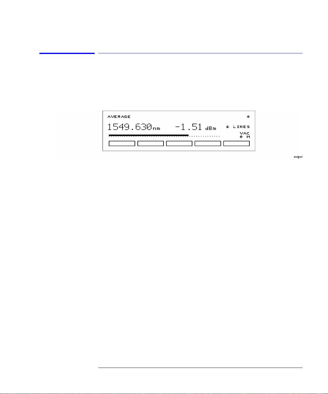
総電力と平均波長
3つめの表示モードとして、次の図のように平均波長の表示が可能です。表示されて
いる電力レベルは、本器への総入力電力です。これは各レーザ線による電力の合計
で、各レーザ線の電力レベルの平均値ではありません。
各レーザ線波長から波長の平均値を求めるには、次の式を使用しています。
n
P
λ
∑
i
∑
=
1
i
n
P
i
=
i
λ
avg
1
--------------------=
i
測定の実施
ここで--
n
=平均に含まれるレーザ線数。
P
=各レーザ線のピーク電力。単位はワット(線形)。
i
2-7
Page 37

測定の実施
波長と電力の測定
各レーザ線電力から電力の合計値を求めるには、次の式を使用しています。
n
=
P
total
ここで
n
=合計に含まれるレーザ線数。
P
=各レーザ線のピーク電力。単位はワット(線形)。
i
i
∑
1
P
i
=
平均波長と総電力を表示するには
Avg WL
キーを押します。
•
測定波長レンジの制限
波長制限機能により、測定する波長のレンジを制限することができます。スタート
波長とストップ波長が指定できます。スタート波長とストップ波長の単位は、現在
選択されている波長単位と同じです。波長単位を後で変更した場合は、スタート波
長とストップ波長の単位も対応して変わります。なお、nmで指定したスタート波長
限界は、THzまたはcm
さい。2-12ページの「測定単位を変更するには」を参照してください。
グラフィック表示の電力スペクトル・プロットでは、波長制限機能のオン/オフにか
かわらず、ここで指定したスタート波長とストップ波長が用いられます。
Presetを押すと、波長制限機能がオンになります。選択されたスタート波長制限値か
らストップ波長制限値までの範囲内にある応答だけが測定されます。これには、
WL、 List by WL、 List by Power
波長レンジを制限するには
Setup
キーを押します。
2
WL LIM
ソフトキーを押します。
-1
を選択するとストップ波長限界になりますので注意してくだ
の各モードが含まれます。
1
Peak
3
STARTWL
4
STOP WL
2-8
ソフトキーを押して、スタート波長を調節します。
ソフトキーを押して、ストップ波長を調節します。
Page 38

測定の実施
波長と電力の測定
広帯域デバイスとチャープ・レーザの測定
最初に電源を投入するか、緑色のPresetキーを押すと、本器は、DFBレーザや各種
モードのFPレーザなどの狭帯域デバイスを測定するように構成されます。LED、光
フィルタ、チャープ・レーザなどの広帯域デバイスを測定したい場合には、まず
メニューを使って本器を構成し直してください。
広帯域デバイスの測定アルゴリズムでは、パワー・スペクトラムの質量中心に基づ
いて波長が決定されます。積分リミット値の決定には、ピーク・エクスカージョン
機能が用いられます。積分リミット値がいずれのノイズよりも上になるように十分
に注意する必要があります。これは特に、EDFA増幅器のようにノイズ・フロアが傾
斜してるデバイスの測定を行う場合に当てはまります。ピーク・エクスカージョン
の詳細については、2-15頁の「レーザ線ピークの定義」を参照してください。
本器の仕様は、本器が狭帯域デバイスを測定するように構成されている場合に適用
されますが、広帯域デバイスを測定するように構成されている場合には適用されま
せん。
広帯域デバイスを測定するには
キーを押します。
Setup
2
3
を2回押してから、
MORE
ソフトキーを押します。
BROAD
狭帯域デバイスの測定に戻るには、
1
ソフトキーを押します。
DEVICES
NARROW
を押します。
Setup
2-9
Page 39

測定の実施
波長と電力の測定
光電力スペクトルのグラフィック表示
スタート波長からストップ波長までの波長に対する光電力をグラフィック表示する
ことができます。スタート波長は画面左上、ストップ波長は右上に示されます。電
力スケールは固定のdBスケールであり、画面上端が+10dBm、下端が-53dBmです。
電力スケールは電力オフセット値に影響されません。ほとんどの場合、全入力電力
が約-5dBmを超えていれば、ノイズ・フロアを見ることができます。
グラフィック表示
ピーク・スレッショルド値は点線で示されます。この点線より上にあるすべてのピー
クが、波長リスト・モードと電力リスト・モードで表示されます。この点より下の
ピークは表示されません。ピーク・スレッショルド値の調整には、
THRSHLD
ソフトキーを使います。
Setup
キーと
波長限界機能がオフであっても、グラフィック表示では波長制限のスタート波長と
ストップ波長が用いられます。
グラフィック表示を印刷することはできません。
グラフィック表示を見るには
1 List by WL
2
GRAPH
グラフィック表示を終了するには、任意のソフトキーを押します。
3
2-10
または
List by Power
ソフトキーを押します。
キーを押します。
Page 40

測定の実施
波長と電力の測定
機器ステート
後に利用するために、4つまでの異なるステートを保存し、リコールすることができ
ます。保存されるステートは、電源オフ時に保存されるものと同じです。詳しくは
7-2頁の表7-1を参照してください。なお、ドリフト測定やアプリケーション(SN比測
定など)が保存時にオンになっていても、リコール時にはオフになることに注意して
ください。
ステートを保存するには :
Setup
キーを押します。
2
SAV/RCL
ソフトキーを押します。
3
SAVE
ソフトキーを押します。
4
1 Setup
2
3
4
SAVE
4個の
ソフトキーのどれかを押すとステートが保存されます。
ステートをリコールするには :
キーを押します。
SAV/RCL
ソフトキーを押します。
RECALL
ソフトキーを押します。
RCL
4個の
ソフトキーのどれかを押すとステートがリコールされます。
パワー・バー
パワー・バーを表示するには
1 Setup
2
キーを押します。
More
を2回押し、次に
PWR BAR
1
を押します。
3
BAR ON
を押して、パワー・バーを表示します。また
の表示がオフになります。
BAR OFF
を押すと、パワー・バー
2-11
Page 41

測定の実施
単位と測定速度の変更
単位と測定速度の変更
本項では、単位および測定速度の変更手順をステップを追って説明します。
本項の内容 :
表示単位 2-12
測定速度 2-13
連続測定と単一測定 2-14
表示単位
本項で後述するように、波長および振幅の表示単位を変更することは容易です。こ
れらの単位は、次のうちから選択できます。
表2-1.可能な単位
波長 電力
nm dBm
–1
cm
THz
測定単位を変更するには
1 Setup
2
3
キーを押します。
MORE
ソフトキーを押します。
UNITS
ソフトキーを押します。
2-12
mW
µ
W
Page 42

測定の実施
単位と測定速度の変更
WL
4
を押し、下記のうちから単位を選択します。
•
NM
5
―ナノメートル
•
THZ
―テラヘルツ
-1
•
CM
―波数
POWER
を押し、下記のうちから単位を選択します。
•
DBM
―1ミリワットに対するデシベル
•
MW
―ミリワット
•
UW
―マイクロワット
RETURN
を押すと、選択が完了します。
測定速度
通常の動作では、本器は約1秒に1度測定を行ない表示します。この通常の速度で、最
高の確度と波長分解能が可能となります。しかし、レーザを目的チャネルに同調さ
せるためにリアルタイム・フィードバックが必要なときなど、もっと速い速度が必
要な場合には、本器は1秒に約2回の更新速度を持つように設定できます。この設定
により波長分解能および確度は低減しますが、アプリケーションによっては有益な
場合があります。
更新モードにおける本器の分解能は7GHz(1550nmで0.06nm)です。この分解能
NORMAL
は、最高5Gb/sの速度でデータを送信する間隔の狭いレーザ線を測定する場合に有用
です。
更新モードにおける本器の分解能は14GHz(1550nmで0.12nm)です。この分解能
FAST
は、最高10Gb/sの速度でデータを送信するレーザ線を測定する場合に有用です。
注記
NORMAL
合には、本器の分解能はレーザ線の変調帯域幅よりも小さくなります。この場
合、表示されるレーザ線の電力は、実際の電力よりも1dBほど小さくなります。
このような電力オフセットは、表示電力をパワー・メータによって測定された
電力と比較することによって計算できます。次に、
を押して電力オフセットを入力すれば、正確な電力を表示できます。
更新モードで10Gb/sの速度でデータを送信するレーザ線を測定する場
Setup
、
MORE
、
CAL
PWR OFS
、
2-13
Page 43

測定の実施
単位と測定速度の変更
測定速度を変更するには
1 Setup
2
3
キーを押します。
MORE
ソフトキーを押します。
UPDATE
ソフトキーを押します。
4
NORMAL
または
FAST
を選択します。
連続測定と単一測定
本器は前面パネル
捕捉の実行中は、画面右上でアスタリスク(*)が表示されます。更新モードをノーマ
ルと高速で切り替えると、アスタリスクの点滅速度が変わります。
また前面パネルの
す。これは単一捕捉測定モードで、これはデータの捕捉と保存に適しています。こ
のようにしてデータを捕捉した後、本章で説明している多くの手順を使用してデー
タを表示できます。連続測定モードには、
きます。
単一捕捉を設定するには
Single
キーを押します。
OPTICAL INPUT
Single
キーを押すと、単一の測定のみを行なえるようにもなりま
•
に入力されるスペクトルを、連続して測定します。
キーを押せばいつでも戻ることがで
Cont
2-14
Page 44

測定の実施
レーザ線ピークの定義
レーザ線ピークの定義
本器では、レーザ線ピークの認識に2つの規則を使用しています。これらの規則を理
解することは、本器による測定を最も有効に利用する上で重要です。たとえばこれ
らの規則によって、AM変調側波帯を「隠し」たり、小振幅のレーザ線を認識したり
できます。
レーザ線を認識するためには、レーザ線は次の規則の両方に適合する必要がありま
す。
•
電力は、ピーク・スレッショルド・リミットの設定する電力よりも大きい。
•
電力は、少なくともピーク・エクスカージョン値だけ上昇し、下降する。
また本項での説明のように、入力波長レンジは制限することもできます。
ピーク・
スレッショルド・
リミット
ピーク・
エクスカージョン
ピーク・スレッショルド・リミットは、最大レーザ線の電力からピーク・スレッショ
ルド値を引くことによって設定されます。したがって最大のレーザ線が2dBmで、ピー
ク・スレッショルド値が10dBのとき、ピーク・スレッショルド・リミットは
となります 。ピーク・スレッショルド値は、0〜40dBの
範囲で設定できます。
ピーク・スレッショルドのデフォルト値は、10dBです。これにより、測定する変調
信号がそのAM側波帯と識別されます。非変調のレーザやファブリペロー・レーザで
は、ピークから10dB以上の応答を得るため、このスレッショルドを増すことが望ま
れます。
ピーク・スレッショルドは、スプリアス信号の抑制にも使用できます。たとえば、音
声周波数レンジにおいて振幅変調されたレーザはスプリアス波長を発生し、それが
正しい波長の上下で表示されることがあります。これらのスプリアス波長の電力は、
正しい波長の電力より下です。したがって、ピーク・スレッショルドをそのプリセッ
ト値から減少することにより、これらのスプリアス波長を除去できます。
ピーク・エクスカージョンは、レーザ線が認識されるために必要な、振幅の上昇と
下降です。上昇と下降はノイズの外、あるいは2つの近接した信号間では隣接信号の
フィルタ・スカートの外です。ピーク・エクスカージョンのデフォルト値は15dBで、
この場合15dB上昇して15dB下降するレーザ線が規則に適合します。ピーク・エクス
カージョン値は、1〜30dBの範囲で設定できます。
8 dBm– 2 dBm 10 dB –=()
−8dBm
2-15
Page 45

測定の実施
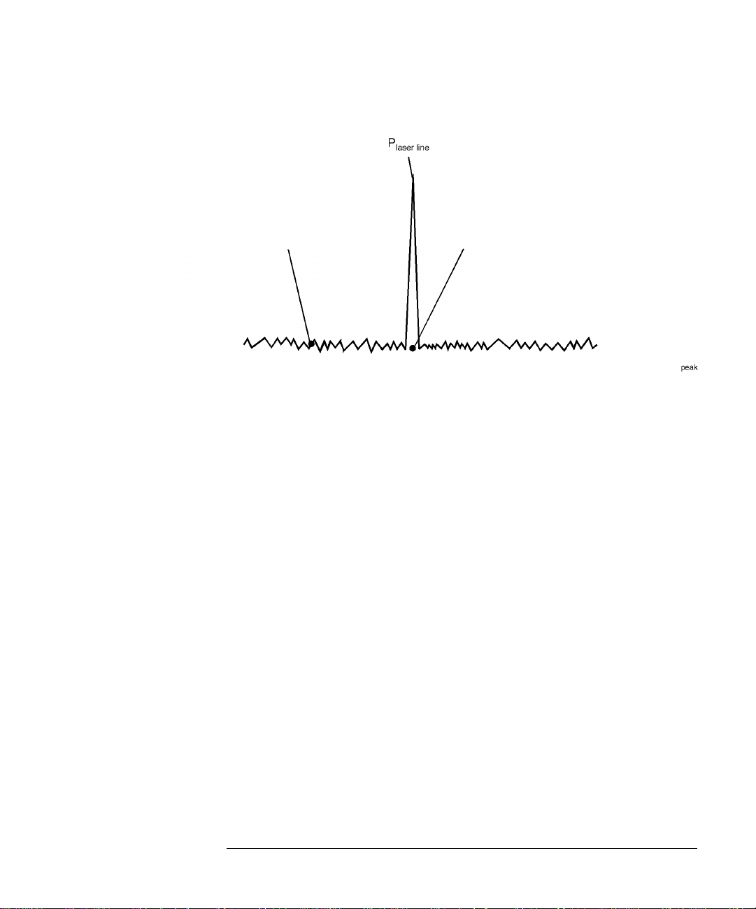
レーザ線ピークの定義
有効な/有効でない
信号の例
次の図では、 ➀、 ➂、 ➃の3つの応答がレーザ線として認識されています。応答 ➁は、
ピーク・スレッショルド以下のため認識されていません。各信号のピーク・エクス
カージョン・リミット内の部分を、太い線で示しています。
➃
ピーク・エクスカージョンの規則により、応答
識されています。
の間の最小点が、ピーク・エクスカージョン・リミットまで
➃と ➄
落ちていないからです。この応答は、最大表示電力、ピーク
および ➄は1つのレーザ線として認
➃
を持ちます。
ピーク・スレッショルド・リミットおよびピーク・エクスカージョン値を変更する
と、本器が
測定モードであっても、それらの新しいリミットが現在表示されて
Single
いる測定に適用されます。
15dBピーク・
エクスカージョン
10dBピーク・
電力(dBm)
スレッショルド
2-16
波長
Page 46

測定の実施
レーザ線ピークの定義
レーザ線ピークを設定するには
1 Setup
2
3
キーを押します。
THRSHLD
PX EXC
て、変更が必要な数字を選択します。 および ソフトキーを使用して、その値を
変更します。
ソフトキーを押します。
を押し、ピーク・エクスカージョン値を入力します。 ソフトキーを使用し
ピーク・エクスカージョン値の許容範囲は1〜30dB、デフォルト値は15dBです。
RETURN
4
5
を押します。
PX THLD
を押し、ピーク・スレッショルド値を入力します。
ピーク・スレッショルド値の許容範囲は0〜40dBです。この値を0dBに設定すると、
ピーク波長のみが認識されるようになります。デフォルト値は、10dBです。
Preset
緑色の
キーを押すと、ピーク・エクスカージョンおよびピーク・スレッショル
ド値はそのデフォルト設定に設定されます。また、波長レンジの制限もオンとなり
ます。本器電源の再投入は、これらの値を変更しません。
ラインの認識過多
次のメッセージが表示されたときは、認識されるレーザ線が多すぎることを示
しています。
E15 MAX NUMBER OF SIGNALS FOUND
本器が測定できるレーザ線の最大数は200です。このメッセージが表示された場
合は、ピーク・スレッショルド値を下げるか、ピーク・エクスカージョン値を
大きくするか、あるいは
レンジを狭くします。
WL LIM ....START WL
および
STOP WL
機能を使って動作波長
2-17
Page 47

測定の実施
レーザ分離の測定
レーザ分離の測定
複数のレーザ線間の、波長および電力の分離を測定することは、往々にして重要で
す。これはチャネル間隔が順守されなければならない波長分割多重(WDM)システム
に、特にあてはまります。本器は、他に相対したどのようなレーザ線の波長および
振幅も表示できます。たとえば、リファレンスに相対した次のような相対測定が可
能です。
•
相対波長、絶対電力
•
相対電力、絶対波長
•
相対波長、相対電力
本項の内容 :
チャネル分離 2-19
平坦度の測定 2-20
2-18
Page 48

測定の実施
レーザ分離の測定
チャネル分離
たとえば、次の図で示すスペクトルを持ったシステムで、分離を測定すると仮定し
ます。
リファレンス
本器はこのスペクトルにおける分離状態を、次の図のように示します。ここでは
1541.747nmレーザ線がリファレンスで、これは絶対単位で表示されています。他の
応答の波長および電力は、このリファレンスに相対した値で示されています。たと
えば、最初の応答はリファレンスより2.596nm下です。
チャネル間隔を求めるには、リファレンスの直前直後のレーザ線に対する、相対波
長測定を読みます。 、 および
ソフトキーを使用して、リファレンスのレー
SELECT
ザ線を変更して、各チャネル間のチャネル間隔を読みます。
2-19
Page 49

測定の実施
レーザ分離の測定
チャネル分離を測定するには
1
前面パネルの
Preset
キーを押します。
2 List by WL
3
Delta Onキーを押します。
測定をオフするには、
4
評価する分離のタイプを選択します。
•
•
5
SELECT
6
任意の時点で
RESET
を押します。
Off
キーを押します。
WL
Δ
により、チャネル分離を表示
WL
Δ
および ソフトキーを使用して、リファレンスのレーザ線を選択します。
PWR
/Δ
により、チャネル分離および電力相違を表示
を押します。
を押せば新しいリファレンスが選択されます。任意の時点で
SELECT
を押せばデルタ測定がオフになります。
平坦度の測定
相対電力測定は、WDMシステムの平坦度(プリエンファシス)の評価に使用できます。
1キャリアをリファレンスとして選択し、他のキャリアをそのリファレンス・レベル
に相対して測定します。これにより電力の相違が、システムの平坦度を表わします。
RESET
を押すとデルタ測定がオフとなり、すべての応答がその絶対波長および電力で
示されます。
平坦度を測定するには
1
前面パネルの
2 List by Power
これにより最大応答を先頭に、入力信号が電力順でリストされます。
3
Delta Onキーを押します。
4
PWR
Δ
5
および ソフトキーを使用して、1番目のレーザ線を選択します。
6
SELECT
7
最大電力の信号がリファレンスのため、他応答の相対電力の測定により、システム
の平坦度が示されます。
2-20
Preset
を押します。
を押します。
を押します。
キーを押します。
Page 50

測定の実施
レーザ・ドリフトの測定
レーザ・ドリフトの測定
この項では、本器を使用したドリフト(レーザ波長および振幅の経時による変化)の測
定について説明します。ドリフトは、入力で認識された各レーザ線について同時に
測定することができます。本器は各レーザ線の初期、現在、最小、最大値をトラッ
キングし、それらを自身に相対した差違として表示します。このためたとえば本器
を、レーザ送信器の評価、バーンイン、開発に使用できます。または時間、温度、そ
の他の条件におけるシステム・パフォーマンスのモニタリングに使用できます。
次の画面例では、5つのレーザ線で測定された電力および波長のドリフトが示されて
います。注釈表示
す。波長および電力に対する現在の相対ドリフト値は、それぞれ
示されています。
示しています。リファレンス値は、測定の開始前に測定されます。
DRIFT
➃
は、現在ドリフト測定を実行中であることを示していま
➀
➁
および ➂によって
は、カーソル が示しているレーザ線のリファレンス絶対値を
RESET
ソフトキーを押すと、ドリフト測定を新しく開始できます。最小および最大値
はリファレンス値にリセットされ、本器は現在のレーザ線値からドリフトのモニタ
を開始します。リスト中でカーソルを上下に動かすことにより、各レーザ線のリファ
レンス波長および電力を見ることができます。
2-21
Page 51
測定の実施
レーザ・ドリフトの測定
測定中に値の更新が停止したり、空白になったときは
測定の途中でレーザ線の数が変わると、もとの数が復活するまで測定は停止し
ます。この場合には
ます。
ソフトキーと、次のいずれかのメッセージが表示され
CLEAR
E46 NUM LINES < NUM REFS
E47 NUM LINES > NUM REFS
状態が変化するまでの測定データを見るには、
捕捉モードは、連続から単一に変わります。
CLEAR
測定を再開するには、
をリファレンスとして使用するために、
定捕捉が再開されます。または入力でもとのライン数を回復して、測定を継続
します。
ドリフトを測定するには
1
前面パネルの
Preset
2 Peak WL、 List by WL
を選択します。
Appl's
、次に
DRIFT
を押すと現在のレーザ線値がリファレンスとして設定され、それに対しすべて
のドリフトが比較されます。
MAX-MIN
4
3
DRIFT
を押して、次に説明するようなドリフト測定のタイプを選択します。
キーを押します。
、または
を押します。
レーザ線の値を、測定を開始したとき、または
を押したときの波長および電力値に相対して表示します。
ドリフト測定を開始して以来の、絶対最大値を表示します。こ
こでは、測定された最大の波長および電力が表示されます。問
題とするレーザ線は以後、より小さい値にドリフトしている可
能性があります。最大波長と最大電力が、同時に発生したとは
限りません。
CONT
、次に
List by Power
キーを押します。そして新しいライン数
そして
CLEAR
RESET
を押します。
を押して、ドリフト測定のための表示形式
MAX-MIN
CONT
を押します。
を押すと連続測
RESET
ソフトキー
2-22
ドリフト測定を開始して以来の、絶対最小値を表示します。こ
こでは、測定された最小の波長および電力が表示されます。問
題とするレーザ線は以後、より大きい値にドリフトしている可
能性があります。最小波長と最小電力が、同時に発生したとは
限りません。
Page 52

測定の実施
レーザ・ドリフトの測定
List by WL
ス値(測定を開始する前の各レーザ線の波長および電力値)を見ることができま
す。
測定の途中で、表示モードを
更できます。
値によってでなく、リファレンス値によってソートされます。
ドリフト測定を新しく開始するには、
値がリセットされます。
および
ドリフト測定を開始して以来の、リファレンスからの総ドリフ
トを表示します。最大波長および電力ドリフト値から最小波長
および電力ドリフト値を引いた値が表示されます。
List by Power
List by WL
表示で は、 およ び ソフトキーによりリファレン
Peak WL、 List by WL、 List by Power
および
List by Power
RESET
表示では、リストは現在値、最大値、最小
を押します。これにより、リファレンス
、または
5
Avg WL
に変
2-23
Page 53
測定の実施
SN比の測定
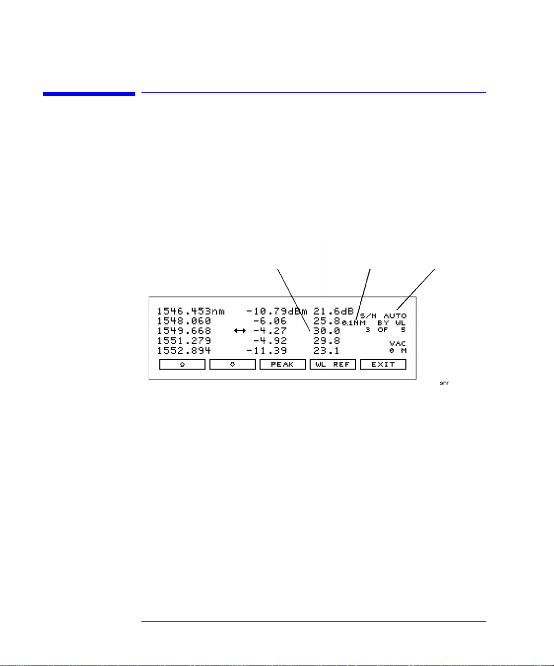
SN比の測定
SN比測定により、システム・パフォーマンスを直接に評価できます。SN比とビット
誤り率との間には直接の関係があるので、SN比測定はWDMシステムにおいて特に重
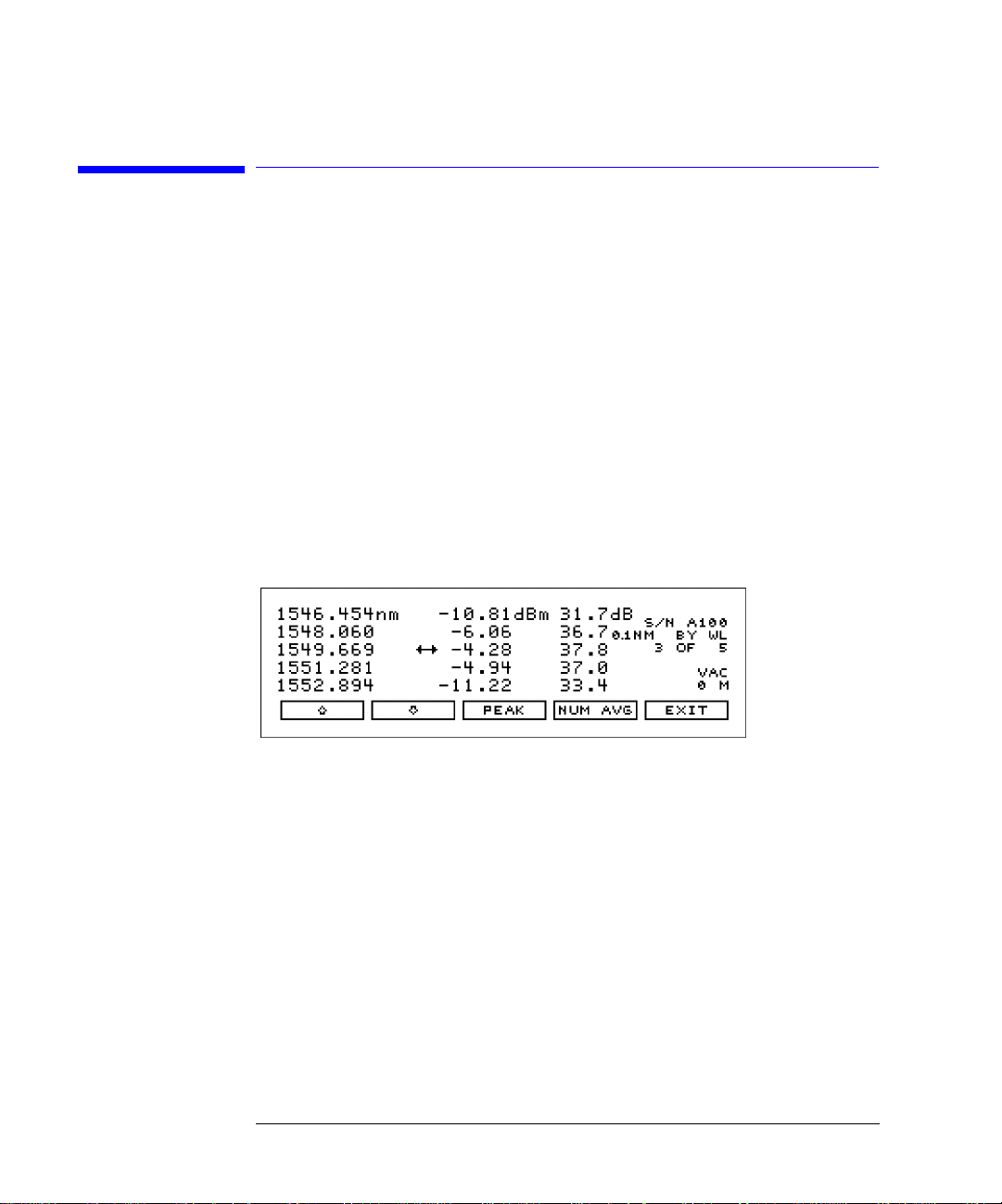
要です。本器はSN比測定を、3番目のカラムで表示します。たとえば次の図で、選択
した信号のSN比は30.0dBです。
SN比測定
ノイズ帯域幅
インディケータ
自動モード
SN比画面
SN比測定では、キャリアの絶対電力(dBm)が、キャリア波長においてノイズの絶対
電力と比較されます。次の図を参照してください。キャリア波長におけるノイズ電
力は、多くの場合キャリアを消すことはできないため、補間によって求めなければ
なりません。
ノイズを測定する波長に対しては、自動補間およびユーザ入力波長の、2つの設定方
法があります。上の図では"
S/N AUTO
"が表示され、自動補間が選択されているこ
とを示します。
2-24
Page 54
測定の実施
SN比の測定
ユーザ入力波長での
ノイズ値
自動モードを使用した
補間ノイズ値
ノイズ測定の位置
自動補間 S/Nの"AUTO"を選択すると、本器はまず隣接した信号の近接性を求めます。問題と
する信号と最も近い信号との距離が≦200GHz(1550nmにおいて約1.6nm)の場合、2
チャネルの中間点と、問題とする信号の反対側の同じ距離だけ離れた点において、ノ
イズ電力が測定されます。次の図の点P
およびPn2を見てください。
n1
問題とする信号と最も近い信号の距離が200GHzを超えるか、または隣接する信号が
ないときは、問題とする信号の両側100GHzの点においてノイズが測定されます。次
に、測定した2つのノイズ・レベルを平均して、問題とする信号波長におけるノイズ
電力レベルを推定します。このノイズ電力測定では、線形補間が使用されます。
2-25
Page 55

測定の実施
SN比の測定
自動補間
ユーザ入力波長 S/Nの"USER"を選択すると、本器はただ1つの波長を使用して、すべての信号に対す
るノイズ電力測定を行ないます。この波長をユーザが設定し、すべての信号をその
波長におけるノイズ電力と比較して、SN比が求められます。
測定に影響する
ノイズ帯域幅
ノイズ電力の測定では、測定で使用するノイズ帯域幅が考慮されなければなりませ
ん。ノイズ帯域幅は測定帯域幅にともなって変動する(広帯域幅の方が狭帯域幅より
本器検出器へのノイズが増える)ため、本器はすべてのノイズ電力測定値を、0.1nm
の帯域幅にノーマライズします。ノイズ帯域幅が0.1nm帯域幅にノーマライズされて
いることを示すため、注釈表示
0.1 nm
が表示されます。
繰り返しデータ・フォーマット
本器のSN比測定は、被測定レーザが変調されていないとき、または非繰り返
しデータ・フォーマットのときに最もよく働きます。PRBSデータやSONETな
どの繰り返しデータ・フォーマットでは、かなりの低周波振幅変調が行なわれ
ています。この変調により、本器のノイズ・フロアが著しく上昇します。繰り
返しデータ・フォーマットで変調されたレーザの測定では、測定SN比は約15dB
に制限されることがあります。レーザが繰り返しデータ・フォーマットで変調
されている場合によい結果を得るには、アベレージングによるSN比測定を使い
ます。
2-26
Page 56

SN比を測定するには
1
前面パネルの
Preset
測定の実施
SN比の測定
キーを押します。
2 List by WL
3 Appl's
4
、次に
ノイズ測定のための波長リファレンスを選択するため、次の手順を行ないます。
WL REF
a
•
または
•
USER
b
を選択したときは、
用して、変更が必要な数字を選択します。 および ソフトキーを使用して、そ
の値を変更します。
RETURN
c
5
SN比測定の表示で、
List by Power
または
S/N
を押します。
を押し、次に―
AUTO
を押して自動補間を選択します。
USER
を押して、手動で入力した最後の波長を選択します。
を押します。
を押します。
USER WL
を押して波長を設定できます。 ソフトキーを使
PEAK
を押せばいつでも最大電力の信号を選択できます。
2-27
Page 57
測定の実施
アベレージングによる SN 比の測定
アベレージングによるSN比の測定
測定対象のレーザが変調されている場合、特にSONETやPRBSのような繰り返しデー
タ・フォーマットで変調されていると、ノイズ・フロアが上がります。アベレージ
ングは、ノイズ・フロアを下げ、SN比を10dB以上改善します。一般的に、アベレー
ジングを用いれば、変調によるノイズ・フロアを真の光ノイズ・レベルにまで下げ
ることが可能です。表示されるSN比は、1回のアベレージごとに改善され、真の光ノ
イズ・レベルに達した時点でほぼ一定になります。ただし、真のSN比が本器の感度
である約40dB(0.1nm ノイズ帯域幅において)よりも小さい場合には測定できませ
ん。
アベレージングにより、変調されていないレーザのSN比測定の確度が向上する場合
もあります。
アベレージングによる SN 比測定画面
アベレージングは、レーザ信号の波長や電力ではなく、ノイズに対して行われます。
アベレージングによるSN比測定では、自動補間法によりノイズを測定する波長が求
められます。自動補間については、「SN比の測定」を参照してください。アベレージ
ングによるSN比測定では、ユーザ入力による波長の選択はありません。
アベレージングによるSN比測定の実行中、ディスプレイには
ます。ここで、Aはアベレージングを表し、xxは現在までのアベレージ回数を示しま
す。アベレージの最大回数は900、最小回数は10で、デフォルト (プリセット)値は
100回になっています。100回のアベレージによる測定には約2分かかります。測定が
終了すると、本器は単一測定モードに入ります。その後、
な測定が始まります。測定実行中でアベレージ回数に達していないときに
Cont
を押すと、測定が停止します。その後、
れます。
2-28
キーを押すと、停止中の測定が再開さ
S/N A xx
Cont
キーを押すと、新た
と表示され
Single
キー
Page 58

測定の実施
アベレージングによる SN比の測定
アベレージングによるSN比測定を実行中に、アベレージ回数を変更することができ
ます。新しい回数が現在までのアベレージ回数よりも多ければ、測定は継続されま
す。新しい回数が現在までのアベレージ回数よりも少ない場合は、測定は停止し、本
器は単一測定モードに入ります。その後、
ます。
キーを押すと、新たな測定が始まり
Cont
測定に影響する
ノイズ帯域幅
ノイズ電力の測定において、測定で使用するノイズ帯域幅が考慮されなければなり
ません。ノイズ帯域幅は測定帯域幅にともなって変動する(広帯域幅の方が狭帯域幅
より本器検出器へのノイズが増える)ため、本器はすべてのノイズ電力測定値を0.1
nmの帯域幅にノーマライズします。ノイズ帯域幅が0.1nmにノーマライズされてい
ることを示すため、注釈表示
アベレージングによってSN比を測定するには
前面パネルの
1
2
List by WL
3
Appl's
アベレージ回数を変更するには、
4
100です。
現在表示されているアベレージ回数で測定を停止させるには、
5
ます。その後、
測定が終了すると、本器は単一測定モードに入り、停止します。
6
新しい測定を開始するには、
7
終了するには、
8
ります。
または
、次に
キーを押します。
Preset
List by Power
を押します。
S/N AVG
キーを押すと現在の測定を再開します。
Cont
ソフトキーを押します。その後、
EXIT
0.10 nm
を押します。
NUM AVG
キーを押します。
Cont
が表示されます。
を押します。デフォルト(プリセット)値は
キーを押し
Single
キーを押すと連続測定に入
Cont
2-29
Page 59

測定の実施
ファブリペロー (FP) レーザの測定
ファブリペロー (FP)レーザの測定
本器は、ファブリペロー・レーザで、FWHMやモード間隔などの数種類の測定を実
行することが可能です。ディスプレイには、測定結果が選択した波長単位と振幅単
位で表示されます。さらに、モード間隔測定では、常に、選択した波長単位だけで
なく、周波数で測定結果が表示されます。単位の変更方法については、2-12頁の「表
示単位」を参照してください。下図に示されているように、測定結果に含まれてい
るレーザ線の数も列挙されます。
ファブリペロー・レーザを特性評価するには
Appl's
を押します。
FP TEST
2
を押して、ファブリペロー・レーザの特性を評価します。
各掃引ごとの測定データの更新を停止したい場合には、
ペロー・レーザは反射に非常に敏感なので、測定を行う場合には、光アイソレータ
か減衰器をレーザと本器の間に配置するのが最適な方法です。
2-30
1
Single
を押します。ファブリ
Page 60

測定 説明
測定の実施
ファブリペロー (FP) レーザの測定
FWHM
MEAN
MODE
PEAK
SIGMA
FWHM(半値全幅)とは、レーザの電力半値ポイントのスペクトル
幅のことを言い、電力は連続したガウス分布であると仮定して
います。また、電力半値ポイントとは、パワー・スペクトル密
度が、計算されたガウス曲線のピーク振幅のパワー・スペクト
ル密度の1/2である電力ポイントのことを言います。
FWHM=2.355σ
ここで、σは下で定義するシグマを表します。
選択されたピークの質量中心を表す波長。平均波長の計算には、
各スペクトル成分の電力と波長が用いられます。
N
λ
i
Σ
=
1
P
i
P
°
平均波長
ここで、P
レーザの個々のスペクトル成分の間の平均波長間隔。
レーザのピーク・スペクトル成分のパワーレベル。ピーク・ス
ペクトル成分の波長。
ガウス分布に基づいたレーザのスペクトル幅の実効値計算。平
均波長の計算には、各スペクトル成分の電力と波長が用いられ
ます。
=
i
は本項で定義している総電力を表します。
o
N
シグマ
ここで、
λ
P
P
=
P
Σ
i
=
i
1
は上で定義した平均波長を表します。
は単一ピークの電力を表します。
i
は本項で定義している総電力を表します。
o
2
λ
()
i
λ –
---------------------
P
o
2-31
Page 61

測定の実施
ファブリペロー (FP) レーザの測定
PWR
ピーク・エクスカージョンとピーク・スレッショルドの設定値によって、測定結果
に含まれるレーザ・モードが定義されます。デフォルトのピーク・エクスカージョ
ン値は10dBなので、通常、測定結果にはピーク応答の10dB以内にすべてのレーザ・
モードが含まれます。測定に用いられるレーザ・モードの数を変更するには、
ソフトキーを使用します。ピーク・スレッショルドとピーク・エクスカージョンの
設定については、2-15頁の「レーザ線ピークの定義」を参照してください。
ピーク・エクスカージョン値(dB)は、測定結果に含めるサイド・モードを決定する場
合にも使用できます。各トレースのピークは、最低でも所定のスペクトル成分のピー
ク・エクスカージョン値分だけ立ち上がった後に立ち下がっていなければ、受け入
れられません。ピーク・エクスカージョン値を高く設定し過ぎた場合には、ノイズ・
フロアの近くのより小さな応答を含めることはできません。また、ピーク・エクス
カージョン値を低く設定し過ぎた場合には、ノイズ・スパイクが含まれた望ましく
ない応答が識別されるおそれがあります。ピーク・エクスカージョン値を変更する
PK EXC
には、
を使用します。
ピーク・エクスカージョンとピーク・スレッショルドの基準を
満たす、選択された各ピークまたはモードの電力の合計。
N
総電力
=
i
Σ
1
=
P
i
PK THLD
2-32
Page 62

測定の実施
変調レーザの測定
変調レーザの測定
低周波数(たとえば音声周波数)において振幅変調されたレーザは、正しい波長の上下
でスプリアス波長を表示することがあります。これらのスプリアス波長の電力は、正
しい波長の電力より下です。このようなスプリアス信号は、ピーク・スレッショル
ド値を下げることによって除去できます。2-15頁「レーザ線ピークの定義」を参照し
てください。レーザが振幅変調されている場合でも、正しい波長と電力が表示され
ます。低周波数の振幅変調で生じたスプリアス波長は、正しい波長の上下に次の間
隔で位置します。
–
間隔
6
10
10
×
2
λ
F
=
ここで、Fは変調周波数(Hz)、λは正しい波長(nm)です。たとえば、1550nmのレー
ザを10kHzで振幅変調した場合、スプリアス波長は正しい波長から15nmの位置、す
なわち1535nmと1565nmに現れます。
低周波数(10kHz)の振幅変調で生じる丸みを帯びた側波帯スプリアス
2-33
Page 63

測定の実施
変調レーザの測定
スプリアス波長を突き止めるには、グラフィック表示が役立ちます。スプリアスの
振幅は正しい波長の振幅よりも小さく、正しい波長が鋭いピークを示すのに対し、ス
プリアスのピークは丸みを帯びた広がった形になります。ピーク・スレッショルド
機能を使って、スプリアスのピークよりも上に点線を持っていくと、スプリアスが
ListbyWLやListbyPowerの表に表示されなくなります。
高周波数(RFやマイクロ波)において振幅変調されたレーザも、スプリアス波長を表
示することがあります。これは特に、PRBSやSONETディジタル・フォーマットな
ど、変調が繰り返し的性質を持つ場合にあてはまります。通常、本器のプリセット・
ステートを使用すると、このようなスプリアス波長は表示されません。プリセット・
ステートには、ピーク・エクスカージョン、ピーク・スレッショルド、波長レンジ
制限などが含まれます。ただし、ピーク・スレッショルドを増すと、スプリアス波
長が表示されることがあります。
被測定レーザが繰り返し形式で変調されていても、キャリアの正しい波長と電力が
表示されます。スプリアス側波帯の波長および電力は、不正なものとなります。
高周波数の変調による影響を見るには、グラフィック表示が役立ちます。変調がな
い場合、ノイズ・フロアは代表的な場合でレーザ電力より45dB下になります。一般
的に、変調によってノイズ・フロアはレーザ電力の約25dB下まで上がります。ノイ
ズ・フロアはフラット(ホワイト)であるのが普通です。ノイズ・フロアの実際のレ
ベルは、データ・フォーマットの種類とデータ・レートに依存します。
PRBS変調によるノイズ・フロアの上昇
2-34
Page 64

測定の実施
10dBmを超える総電力の測定
10dBmを超える総電力の測定
本器が測定できる最大の総電力は、10dBmです。しかし外部減衰器を付加すれば、よ
り大きな電力が印加できます。これは、大きな信号レベルが存在する波長分割多重
システムの伝送終端などで必要になります。本器入力における減衰量と等しい振幅
オフセットを設定することにより、正確な振幅測定値を表示できます。追加の増幅
に対するオフセットも可能です。
注意 本器に対する安全な(本器を損傷しない)総入力電力は、最大18dBmです。また本器が
測定できる総入力電力は、最大10dBmです。
10dBmを超える総電力を測定するには
前面パネル
1
この減衰器により、本器への総入力電力が+10dBm以下になるようにします。
2 Setup
画面に注釈表示
す。
ソフトキーを使用して、変更が必要な数字を選択します。
3
および ソフトキーを使用して、その値を変更します。
4
電力オフセット値は、表示電力値に加えられます。たとえば前面パネルの入力で10dB
の減衰器を接続した場合は、+10dBの電力オフセット値を入力します。減衰器に代え
て増幅器を接続した場合には、マイナスの値を入力します。
、
MORE
OPTICAL INPUT
、
CAL
PWR OFS
と光ファイバ・ケーブルとの間に、光減衰器を挿入します。
、
PWR OFS
を順に押します。
が表示されて、オフセットが加えられていることを示しま
2-35
Page 65

測定の実施
測定の校正
測定の校正
光の波長は、光が通過する媒体によって変化します。意味のある波長測定を行なう
ために、本器では次の2つの手順を行ないます。
1
空気中の波長を測定
2
その波長を、真空または「標準大気」での値を示すように変換
たとえば真空中で1550.000nmの波長を示すレーザ線は、標準大気では1549.577nmと
なります。
本器の中で行なわれるすべての測定は空気中となるため、標高による空気密度が測
定結果に影響します。そのため、標高値を入力することによって、本器を校正する
必要があります。入力できる範囲は、0〜5000メートルです。本器が単一捕捉モード
にあっても、標高による補正は現在の値にすぐに加えられます。
画面では、現在の標高校正値がメートルで注釈表示され、また測定値が真空(
STD AIR
対するものか、標準大気(
波長に代えて周波数を選択した場合は、「真空」と「標準大気」を切り替えても測定
結果に影響しません。これは、光信号の周波数は媒体によって変化せず、波長だけ
が変化するからです。
)に対するものか示されます。
VAC
)に
標準大気の定義
標準大気の定義特性は、次の通りです。
気圧:
温度:
相対湿度:
2-36
760 torr
15
°
C
0%
Page 66

測定の実施
測定の校正
標高値を入力するには
1 Setup
2
3
4
5
6
キーを押します。
MORE
ソフトキーを押します。
CAL
ソフトキーを押します。
ELEV
を押します。
および ソフトキーを使用して、標高値をメートルで入力します。値は、0〜5000m
の範囲で500mの増分により変化します。
本器がその仕様を満足するには、ここで選択する標高値が実際の標高の250m以内で
ある必要があります。
RETURN
を押して入力を終了します。
フィートからメートルへの換算
標高値がフィートの場合、次の式を使ってメートルに換算できます:
m
媒体を選択するには
Setup
キーを押します。
2
MORE
ソフトキーを押します。
3
CAL
ソフトキーを押して、次の選択を行ないます。
•
真空中の波長を表示するには
•
標準大気中の波長を表示するには
4
RETURN
を押して入力を終了します。
1
VACUUM
-------------- -=
3.281
を押す
STD AIR
ft
を押す
2-37
Page 67

測定の実施
測定結果の印刷
測定結果の印刷
測定結果をプリンタに直接送ることが可能です。これには使用可能なプリンタを、裏
面パネルの
使用可能なプリンタにはHPLaserJetシリーズなどがあります。プリンタの接続には、
パラレル・プリンタ・ケーブルを使用します。
このプリンタ出力内容は表示画面と同じではなく、入力されている全信号(最大200)
のリストとなります。印刷される測定値は、
よります。次に示すのは、プリント出力の例です。
HP 86120C SER US39400020
Firmware Ver. 1.000
List By Wavelength
8 Lines
Power Offset 0.0 dB
Vacuum
Elevation 0 Meters
Update Normal
Peak Excursion 15 dB
Peak Threshold 10 dB
PARALLEL PRINTER PORT
に接続します。出力されるのはASCIIテキストで、
Print
キーを押したときの本器の設定に
Input
Wavelength
1280.384nm -16.97dBm
1281.473 -13.14
1282.569 -13.92
1283.651 -13.34
1284.752 -11.69
1285.840 -8.11
1286.944 -10.38
1288.034 -14.65
ハードコピーを作成するには
本器裏面パネルの
1
キーを押します。
2 Print
動作を停止/再開します。
2-38
Power
PARALLEL PRINTER PORT
ABORT
および
に、プリンタを接続します。
ソフトキーを押すことにより、それぞれ印刷
CONT
Page 68

測定の実施
正確な測定を行うための接続部分の清掃
正確な測定を行うための接続部分の清掃
今日では、測定機能の進歩によって、コネクタや接続技術がこれまで以上に重要に
なっています。校正機器や検証機器のコネクタ、テスト・ポート、ケーブル、およ
びその他のデバイスに損傷があると、測定確度が劣化する上に、機器に損傷が及ぶ
おそれがあります。損傷コネクタを交換することになれば、無駄な時間を費やすだ
けでなく、莫大な費用がかかる可能性があります。このような出費は、本書に記載
されている簡単な注意事項を守ることによって避けることができます。本書には、電
気的コネクタの手入れ方法に関するヒントも列挙されています。
適切なコネクタの選択
正確な光測定を行う上で重要ではあるものの見落とされがちな要因の1つとして、光
ファイバ・コネクタの選択があります。各種コネクタ・タイプの違いは、主に、フェ
ルールを別のまったく同種のフェルールに対して正しい位置に保持するメカニカ
ル・アセンブリにあります。クラッド内のコアの研磨、曲率半径、および同心性も
コネクタによって異なります。あるタイプのケーブルを別のタイプのケーブルに接
続するためには、アダプタが必要です。HPではほとんどの測定器に対して多様なHP
アダプタを提供しており、各種ケーブルによるテストが可能です。2-40頁の図2-3に、
代表的なコネクタの基本コンポーネントを示します。
現在用いられている多種多様なコネクタの中からコネクタを選択するには、反射や
挿入損失に関するシステムの許容範囲を知る必要があります。コネクタを選択する
際に考慮すべき事柄を以下にいくつか列挙します。
•
挿入損失の許容範囲は?
•
コネクタで何度も接続を行う必要があるか?コネクタの中には、他のコネクタよりも
反復接続に適しているものもあれば、反復接続にまったく適していないものもあり
ます。
•
反射許容範囲は?システムに反射劣化が生じる可能性があるか?
•
精密なコア・アライメントの測定器グレード・コネクタが必要か?
•
反射や損失に関する再現性の許容範囲は重要か?仕様には再現性の不確実さが考慮
2-39
Page 69

測定の実施
正確な測定を行うための接続部分の清掃
に入れられているか?
• コネクタがリターン・ロスを大幅に劣化させる可能性はあるか?あるいは融着接続が
必要になる可能性はあるか?たとえば、多くのDFBレーザは、コネクタからの反射が
あると動作しません。しばしば、90dBのアイソレーションが必要となります。
ボディとメカニカル・
リテナの接続
ファイバ125um
(実際のファイバの直径は、
人間の毛髪よりも細い)
フェルール2.5mm
アライメント・キー
図2-3. コネクタの基本的なコンポーネント
この2、3年の間に、FC/PC型のコネクタが光ファイバ・アプリケーション用の最も一
般的なコネクタとなっています。このコネクタは、最高の性能を備えたコネクタで
あるとは言えませんが、性能、信頼性、コストを総合すると非常に優れたコネクタ
です。このコネクタは、保守や清掃を正しく行いさえすれば、何度でも繰り返し接
続できます。
しかし、多くの測定器仕様では、FC/PC型を含むほとんどのコネクタより厳しい許容
範囲が求められています。これらの測定器には、セラミック型のフェルールと同様、
ファイバの非同心性が大きいコネクタを使用することはできません。より厳密なア
ライメントが求められる場合、HPの測定器には、通常、同心性の許容値が1ミクロン
の10分の2から3以内である、DiamondHMS-10などのコネクタが用いられています。
したがってHPでは、他の種類のケーブルをこのような精密コネクタに接続できるよ
うにする、特殊なユニバーサル・アダプタを使用しています。2-41頁の図2-4を参照
してください。
2-40
Page 70

測定の実施
正確な測定を行うための接続部分の清掃
図2-4. DiamondHMS-10 用のユニバーサル・アダプタ
HMS-10の場合、丈夫な炭化タングステン製のケーシングで囲まれた軟質洋銀(Cu/Ni/
Zn)の中心にファイバが入っています(図2-5を参照)。
ステーキ溝
(固定操作)
2次ステーキング
(アクティブ・センタリング)
洋銀(Cu/Ni/Zn)
(軟質の中心)
125umファイバ
(中心約0.2 µmまで移動)
炭化タングステン
(ハード・ケース)
図2-5. DiamondHMS-10 コネクタの断面図
洋銀を用いることによって、グラスファイバを希望の方向に移動できるようにする
アクティブ・センタリング・プロセスが可能になります。このプロセスでは、まず
軟質洋銀でファイバを中心近くに固定します。次に、ポスト・アクティブ・ステー
キングを使って、ファイバを0.2 µmの範囲内で希望の位置に移動させます。このプロ
セスに加え、軸の固定によって、非常に精密なコア・ツー・コアのアライメントが
可能になっています。このコネクタは、ほとんどのHPの光測定器に用いられていま
す。
2-41
Page 71

測定の実施
正確な測定を行うための接続部分の清掃
ソフト・コアは、正確なセンタリングを可能にしますが、コネクタの主要な障害と
もなっています。軟質素材は損傷を受けやすいので、過度の傷や摩耗を最小限に抑
えるように十分に注意する必要があります。ガラスの表面に影響がなければ多少の
摩耗は問題ありませんが、傷やほこりがあるとグラスファイバのアライメントがず
れるおそれがあります。また、固定されていないコネクタを使用した場合には、ガ
ラスの表面に洋銀が押し付けられる可能性があります。傷、ファイバの移動、ガラ
スの汚れは、信号の損失や反射を増加させるため、リターン・ロスが劣化します。
コネクタの点検
光ファイバ・コネクタは肉眼では識別し難い損傷を受けやすいので、コネクタに問
題があることに気が付かないまま、誤った測定を行う可能性があります。接続部分
を良好な状態に保つためには、顕微鏡で検査し、リターン・ロスを測定するのが最
善の方法ですが、必ずしも実用的ではありません。潜在的な問題を認識し、適切な
清掃を行うことによって、最適なコネクタの性能を維持することが可能です。ガラ
ス間の界面が存在するので、フェルールやファイバ先端の劣化、飛沫片、あるいは
指の油がコネクタの性能に重大な影響を及ぼすことは明らかです。
図2-6は、汚れのないきれいな光ファイバ・ケーブルの先端を示したものです。顕微
鏡写真の中央にある黒い円は、光を伝搬するファイバの125 µmのコアとクラッドで
す。周囲は軟質洋銀製のフェルールです。図2-7は、清掃していないか不適切な清掃
が原因と思われる、汚れたファイバの先端を示したものです。素材に汚れがあり、
ファイバの先端に強く押し付けられているため、光が散乱し、反射が悪くなってい
ます。このため、精密な研磨が失われているだけでなく、ガラスの表面が擦り取ら
れ、コネクタが破壊されるおそれがあります。
図2-8は、飛沫片を取り除かずに繰り返し接続したか、不適切な清掃用ツールを使っ
たことに起因する、グラスファイバ先端の物理的損傷を示したものです。深刻な場
合には、一方のコネクタ先端の損傷が、それに接触するもう一方の問題のないコネ
クタにも移る可能性があります。
このような問題を解決するためには、以下のリストおよび2-45頁の「コネクタの清掃
方法」に記載されている通りに、コネクタの手入れを行ってください。
光ファイバ・システムで測定を行う場合には、以下の指針に従って、可能な限り最
高の性能を実現してください。
コネクタを清掃する場合には、金属製のものや先の尖ったものは絶対に使用しない
•
でください。また、絶対にコネクタをこすらないでください。
整合用のジェルや油は使用しないでください。
•
2-42
Page 72

正確な測定を行うための接続部分の清掃
図2-6. きれいで、問題のないファイバ先端とフェルール
測定の実施
図2-7. 不十分な清掃が原因で汚れているファイバ先端とフェルール
図2-8. 不適切な清掃に起因する損傷
ジェルや油は、しばしば、最初の挿入時には正しく機能しますが、汚れを引き寄せ
る磁石となります。油やジェルにほこりが付着し、付着したほこりがファイバの先
端に押し付けられことになります。さらに、昔のジェルの中には、小さなガラス球
2-43
Page 73

測定の実施
正確な測定を行うための接続部分の清掃
を使用する、FC非接触型コネクタへの使用を目的としているものもあります。この
ジェルを接触型コネクタに使用すると、ガラス球によってファイバに傷が付いたり、
穴があいてしまうおそれがあります。屈折率整合剤や油を使用しなければならない
場合には、清掃直後のコネクタに適用し、測定を行ったらすぐに拭き取ってくださ
い。長期間にわたる接続や、損傷しているコネクタの改善には、絶対にジェルを使
用しないでください。ジェルは損傷範囲を覆い隠してしまうので、損傷しているファ
イバをいつまでも使い続けることになります。このため、損傷が測定器にまで及ぶ
おそれがあります。
•
光ファイバ・ケーブルをコネクタに挿入する場合には、できるだけ線がまっすぐに
なるようにしてゆっくりと挿入してください。角度を付けて挿入すると、コネクタ
の内側の素材を傷つけ、セラミック製のコネクタの内側のスリーブが破損してしま
う可能性があります。
•
光ファイバ・コネクタをコネクタに挿入する場合には、ファイバの先端が差込み式
のコネクタやアダプタの外側に触れないようにしてください。
•
接続部分を強く締め過ぎないようにしてください。
一般的な電気的接続部分とは違って、締め過ぎは好ましくありません。コネクタの
目的は、2つのファイバ先端を1 つに合わせることにあります。両端が接触した後に
強く締め付けても、傷つきやすいファイバに大きな力が加わるだけです。ファイバ
の先端が凸状になっているコネクタの場合は、先端が軸からずれて押し付けられる
ことがあるので、アライメント不良や過度のリターン・ロスが発生する可能性があ
ります。実際に、コネクタにかかる圧力を取り除くことによって、多くの測定が改
善されています。さらに、清掃によって小さなほこりが付着してしまった場合には、
接続部分を締め過ぎるとガラスを損傷するおそれが高くなります。コネクタは、2本
のファイバが触れ合う程度に締めるようにしてください。
•
使用していないときは、コネクタにカバーを付けてください。
•
より永久的な重要なノードには、融着接続法を用いてください。可能な限り最適な
コネクタを選択してください。接続ケーブルは定期的に交換してください。コネク
タのリターン・ロスを頻繁に測定して劣化をチェックし、常にすべてのコネクタを
清掃するようにしてください。
コネクタはすべて、性能の高いカメラの高品質レンズと同じように取り扱ってくだ
さい。コネクタの不適切な使用や手入れは、測定器やシステムの信頼性を低下させ
ることになります。現在用いられているコネクタは非常に使用が簡単なので、コネ
クタの手入れや清掃に対する警戒心が弱まっています。小さなほこりを見逃さない
で清掃を行えば、ガラスに永久的な損傷が及ぶことも、コネクタを駄目にすること
もありません。
挿入損失とリターン・ロスの測定
使用する光測定器で一貫した測定が行えれば、接続に問題はありません。リターン・
ロスと挿入損失は光コネクタの性能を決定する際の重要な要因であるため、コネク
タの劣化の確認に使用できます。ファイバの先端が滑らかに研磨されていれば、正確
2-44
Page 74

測定の実施
正確な測定を行うための接続部分の清掃
なリターン・ロス測定を行うことができるはずです。研磨の質が、"PC"(物理接触)コネ
クタと"SuperPC"コネクタの違いとなります。今日用いられているコネクタのほとん
どが物理接触型であり、ガラス間を接続します。このため、ガラス・コアの周囲の領域
をきれいにして、傷のない状態に保つことが非常に大切です。コネクタのガラスを除
くほとんどの領域に傷や摩耗が見られても、ガラスを研磨した滑らかな状態に保て
ば、コネクタは、良好なロー・レベル・リターン・ロス接続を提供し続けます。
受領時にケーブルやアクセサリの挿入損失/リターン・ロスをテストして、その測定
データを比較用に残しておくと、後で劣化の発生を知ることができます。この損失
は一般的には0.5dB未満であり、高性能のコネクタでは0.1dBのこともあります。ま
たリターン・ロスは反射の単位であり、反射が少ないほどパフォーマンスが良いこ
とになります(リターン・ロスが大きいほど、反射が少なくなります)。高性能の物理
接触コネクタは50dB以上のリターン・ロスを持ちますが、30〜40dBが一般的です。
ファイバ先端の目視点検
ファイバ先端の目視による点検は有効です。これによりケーブル先端面の汚れや損
傷だけでなく、ファイバ自体の割れや欠けあとを見つけることができます。顕微鏡
(100〜200倍)を使用して、先端面全体を汚れ、メタルの凹凸、その他の不具合がない
か調べます。ファイバに割れや欠けあとがないかも見ます。目で見える不具合であっ
てもファイバ・コアに達していなければ(ファイバの接触を妨げないかぎり)、パ
フォーマンスに影響しない場合があります。
コネクタの清掃
本項では、光ファイバ・ケーブルやHPユニバーサル・アダプタを清掃する際の適切
な手順について説明します。まず、アルコールを溶剤として用い、ほこりや油をす
べて取り除きます。物質が固まり付いたまま取れない場合には(これは、ケーブルの
挿入中にフェルール保持器のベリリウム銅側がこすり落とされ、ファイバの先端に
堆積した場合に発生する可能性があります)、もう1度清掃を行ってください。ケーブ
ルやコネクタの清掃は、しばしば2度以上行う必要があります。
2-45
Page 75

測定の実施
正確な測定を行うための接続部分の清掃
注意 HP では、屈折率整合剤を HP 測定器やアクセサリに使用しないよう強くお勧めしま
す。ジェルなどの整合剤は除去するのが難しく、また傷のもととなる粒子などを含
むことがあります。どうしても整合剤をお使いになるときは、製造者に使用方法や
クリーニング方法についてお問い合わせください。
表2-2.清掃用アクセサリ
品目 HP部品番号
イソプロピル・アルコール 8500-5344
綿棒 8520-0023
小型スポンジ綿棒 9300-1223
圧縮空気(無残留物) 8500-5262
表2-3.光測定器付属ダスト・キャップ
品目 HP部品番号
レーザ・シャッタ・キャップ 08145-64521
FC/PCダスト・キャップ 08154-44102
Biconicダスト・キャップ 08154-44105
DINダスト・キャップ 5040-9364
HMS10/HPダスト・キャップ 5040-9361
STダスト・キャップ 5040-9366
ノンレンズ・コネクタの清掃方法
注意 スポンジ綿棒は、光ファイバ先端のクリーニングには使用しないでください。スポ
ンジ綿棒は清掃した表面に皮膜を残し、パフォーマンスの低下を招くことがありま
す。
1
清潔な毛羽立っていない綿棒、またはレンズ・ペーパーに純粋のイソプロピル・ア
ルコールを浸します。
綿棒を使用する場合は、清掃後ファイバ先端に繊維が残らないよう注意してくださ
い。
2-46
Page 76

測定の実施
正確な測定を行うための接続部分の清掃
2 ファイバの先端は避けながら、コネクタのフェルールやその他の部分を清掃します。
3 清潔な新しい毛羽立っていない綿棒、またはレンズ・ペーパーにイソプロピル・ア
ルコールを浸します。
4 綿棒またはレンズ・ペーパーでファイバ先端を清掃します。
ほこりが綿棒について表面をえぐり取ってしまう可能性があるので、最初の清掃で
は、ごしごしこすらないでください。
5 すぐに清潔で乾いた毛羽立っていない綿棒、またはレンズ・ペーパーでファイバ先
端を拭き取ります。
6 濾過済みの乾いた圧縮空気を15〜20cmの距離からコネクタ端面に吹きつけます。圧
縮空気は、ファイバ先端面に対し浅い角度から吹きつけてください。
窒素ガスや圧縮ダスト・リムーバも使用できます。
注意 圧縮空気の缶中の粒子が空気中に出てしまうため、吹きつけるときに缶を振ったり、
傾けたり、逆さにしないでください。詳しくは圧縮空気の缶の注意書きをお読みく
ださい。
コネクタが乾燥したらすぐに接続するか、またはキャップを着けます。
7
最初の清掃が終わっても性能が劣っていると思われる場合には、もう1度コネクタを
清掃してみてください。たいていの場合は、もう1度清掃すれば、本来の性能を取り
戻すことができます。2回目の清掃は、こするなど、より時間をかけて行います。
アダプタの清掃方法
多くのHP測定器の光ファイバ入出力コネクタが、下図に示すようなユニバーサル・
アダプタを採用しています。これらのアダプタを用いることによって、測定器を各
種光ファイバ・ケーブルに接続することができます。
図2-9. ユニバーサル・アダプタ
1
清潔なスポンジ綿棒に、イソプロピル・アルコールを浸します。
綿棒を使用する場合は、清掃後に繊維が残らないように注意してください。本項の
初めで紹介したスポンジ綿棒は小型で、アダプタ内部の清掃に適しています。
2-47
Page 77

測定の実施
正確な測定を行うための接続部分の清掃
スポンジ綿棒の使用により、後に皮膜が残ることがあります。しかし、この皮膜は
たいへん薄く、アダプタ内部に付着しやすい他の汚れに比較すれば、問題はありま
せん。
2 スポンジ綿棒でアダプタを清掃します。
3 清潔で乾いたスポンジ綿棒でアダプタ内部を拭き取ります。
4 濾過済みの乾いた圧縮空気をアダプタ内外に吹きつけます。
窒素ガスや圧縮ダスト・リムーバも使用できます。圧縮空気の缶中の粒子が空気中
に出てしまうため、吹きつけるときに缶を振ったり、傾けたり、逆さにしないでく
ださい。詳しくは圧縮空気の缶の注意書きをお読みください。
2-48
Page 78

3
Addressing and Initializing the Instrument 3-3
To change the HP-IB address 3-4
Making Measurements 3-5
Commands are grouped in subsystems 3-7
Measurement instructions give quick results 3-9
The format of returned data 3-15
Monitoring the Instrument 3-16
Status registers 3-17
Queues 3-22
Reviewing SCPI Syntax Rules 3-23
Example Programs 3-28
Example 1. Measure a DFB laser 3-30
Example 2. Measure WDM channels 3-32
Example 3. Measure WDM channel drift 3-34
Example 4. Measure WDM channel separation 3-37
Example 5. Measure signal-to-noise ratio of each WDM channel 3-39
Example 6. Increase a source’s wavelength accuracy 3-41
Lists of Commands 3-43
Programming
Page 79

Programming
Programming
Programming
This chapter explains how to program the HP 86120C. The programming syntax conforms to the IEEE 488.2 Standard Digital Interface for Programmable
Instrumentation and to the Standard Commands for Programmable Instruments (SCPI).
Where to begin…
The programming examples for individual commands in this manual are written in HP BASIC 6.0 for an HP 9000 Series 200/300 Controller.
For more detailed information regarding the HP-IB, the IEEE 488.2 standard,
or the SCPI standard, refer to the following books:
Hewlett-Packard Company. Tutorial Description of Hewlett-Packard Inter-
face Bus, 1987.
Hewlett-Packard Company. SCPI—Standard Commands for Programmable
Instruments, 1995.
International Institute of Electrical and Electronics Engineers. IEEE Standard
488.1-1987, IEEE Standard Digital Interface for Programmable Instrumentation. New York, NY, 1987.
International Institute of Electrical and Electronics Engineers. IEEE Standard
488.2-1987, IEEE Standard Codes, Formats, Protocols and Common commands For Use with ANSI/IEEE Std 488.1-1987. New York, NY, 1987.
Types of commands
The HP 86120C responds to three types of commands:
• Common commands
• Measurement instructions
• Subsystem commands
All of these commands are documented in Chapter 4, “Programming Commands”.
3-2
Page 80

Programming
Addressing and Initializing the Instrument
Addressing and Initializing the Instrument
The HP 86120C’s HP-IB address is configured at the factory to a value of 20.
Y ou must set the output and input functions of your programming language to
send the commands to this address. You can change the HP-IB address from
the front panel as described in “To change the HP-IB address” on page 3-4.
Remote mode and front-panel lockout
Whenever the instrument is controlled by a computer, the Remote message is
displayed on the instrument’s screen and the softkey menu is blanked except
for the
panel control of the instrument.
You can specify a local lockout mode that prevents the
being displayed. If the instrument is in local lockout mode, all the softkeys
may be blanked. For example, if the instrument is first placed in local lockout
mode and then placed in remote mode, no softkeys are displayed.
Consult the documentation for your programming environment to determine
which commands are used to put an instrument in the remote and local lockout modes. These are not HP 86120C commands; they control HP-IB control
lines and do not send any characters to the HP 86120C.
LOCAL
softkey. This softkey can be pressed by the user to restore front
LOCAL
softkey from
Initialize the instrument at start of every program
It is good practice to initialize the instrument at the start of every program.
This ensures that the bus and all appropriate interfaces are in a known state.
HP BASIC provides a CLEAR command which clears the interface buffer and
also resets the instrument’s parser. (The parser is the program that reads the
instructions that you send.) Whenever the instrument is under remote programming control, it should be in the single measurement acquisition mode.
This is automatically accomplished when the *RST common command is used.
The *RST command initializes the instrument to a preset state:
CLEAR 720
OUTPUT 720;”*RST”
Notice in the example above, that the commands are sent to an instrument
address of 720. This indicates address 20 on an interface with select code 7.
Pressing the green Preset key does not change the HP-IB address.
3-3
Page 81

Programming
Addressing and Initializing the Instrument
Set single acquisition mode
An advantage of using the *RST command is that it sets the HP 86120C into
the single measurement acquisition mode. Because the READ and MEASure
data queries expect this mode, their proper operation is ensured.
To change the HP-IB address
Press the Setup key.
Press
MORE
twice, then
3
Use the and softkeys to change the HP-IB address.
4
Press
RETURN
.
HP-IB
1
2
.
3-4
Page 82
Programming
Making Measurements
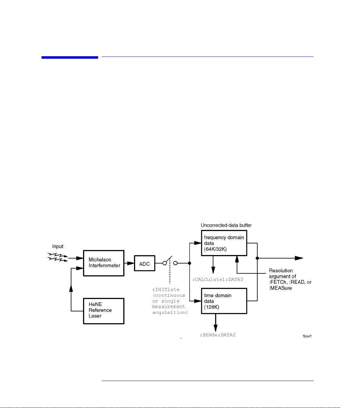
Making Measurements
Making measurements remotely involves changing the HP 86120C’s settings,
performing a measurement, and then returning the data to the computer. The
simplified block diagram of the HP 86120C shown here lists some of the available programming commands. Each command is placed next to the instrument section it configures or queries data from.
Notice that there are two buffers from which data can be queried: an uncorrected data buffer and a corrected data buffer. With each scan of the input
wavelength range, the analog-to-digital converter loads 65,536 data values
into the uncorrected data buffer. This is considered to be one “measurement”.
A fast-update measurement mode is available for quicker measurement acquisition. But, because only 32,768 data values are collected in fast-update measurement mode, the ability to resolve closely spaced signals is reduced.
3-5
Page 83

Programming
Making Measurements
After collecting the uncorrected data, the HP 86120C searches the data for
the first 200 peak responses. (For WLIMit:OFF, searching starts at 1650 nm
and progresses towards 1270 nm. For WLIMit:ON, searching starts at
WLIMit:START and progresses toward WLIMit:STOP.) These peak values are
then placed into the corrected data buffer. Each peak value consists of an
amplitude and wavelength measurement. Amplitude and wavelength correction factors are applied to this data.
For a listing of the programming commands (including a cross reference to
front-panel keys), refer to the following tables:
Table 3-7, “Programming Commands,” on page 3-43
Table 3-8, “Keys Versus Commands,” on page 3-49
3-6
Page 84

Programming
Making Measurements
Commands are grouped in subsystems
The HP 86120C commands are grouped in the following subsystems. You’ll
find a description of each command in Chapter 4, “Programming Commands”.
Subsystem Purpose of Commands
Measurement
Instructions Perform frequency, wavelength, and wavenumber
measurements.
CALCulate1 Queries
CALCulate2 Queries
CALCulate3 Performs delta, drift, signal-to-noise, and Fabry-Perot
measurements.
DISPlay Applies markers and displays power bars.
HCOPy Prints measurement results.
SENSe Sets elevation-correction values, selects readings for air or
vacuum, and enters amplitude offsets. Queries time-
domain values of the input data.
STATus Queries instrument status registers.
SYSTem Presets HP 86120C and queries error messages.
TRIGger Stops current measurement. Acquires new measurement
data. Also used to select single or continuous acquisition of
measurement data.
UNIT Sets the amplitude units to watts or dBm.
Table 3-1 on page 3-8 shows the kinds of measurements that the HP 86120C
can perform and the associated programming commands used to return that
data. In some cases, there is more than one method that can be used to obtain
the desired data. Refer to Chapter 4, “Programming Commands” for the correct syntax for these commands.
uncorrected
corrected
peak data and sets wavelength limits.
frequency-spectrum data.
3-7
Page 85

Programming
Making Measurements
Table 3-1. Commands for Capturing Data
Desired
Measurement
Wavelength (nm) CONFigure, FETCh, READ, and MEASure MEASure:ARRay:POWer:WAVelength?
Frequency (THz) CONFigure, FETCh, READ, and MEASure MEASure:ARRay:POWer:FREQuency?
Wavenumber (m–1)
Power (W, dBm) CONFigure, FETCh, READ, and MEASure MEASure:ARRay:POWer?
Average Wavelength,
Wavenumber, or Frequency
Total Power (W, dBm) CALCulate2:PWAVerage:STATe CALCulate2:DATA?
Fabry-Perot Laser CALCulate3:FPERot Refer to “FPERot[:STATE]” on page 4-58
Laser-Line Separation CALCulate3:DELTa:REFerence CALCulate3:DATA?
Laser-Line Drift CALCulate3:DRIFt:STATe CALCulate3:DATA?
Signal-to-Noise Ratio CALCulate3:SNR:STATe CALCulate3:DATA?
Signal-to-Noise Ratio Average CALCulate3:ASNR:STATe CALCulate3:DATA?
Time-Domain Data CALCulate1:TRANsform:FREQuency:POINts SENSe:DATA?
Corrected Frequency Domain Data CALCulate1:TRANsform:FREQuency:POINts CALCulate2:DATA?
Uncorrected Frequency Domain
Data
Command to Configure Measurement
(partial listing)
CONFigure, FETCh, READ, and MEASure MEASure:ARRay:POWer:WNUMber?
CALCulate2:PWAVerage:STATe CALCulate2:DATA?
CALCulate1:TRANsform:FREQuency:POINts CALCulate1:DATA?
Command to Query Data
3-8
Page 86

Measurement instructions give quick results
The easiest way to measure wavelength, frequency, or power is to use the
MEASure command. The MEASure command is one of four measurement
instructions: MEASure, READ, FETCh, and CONFigure. The syntax for measurement instructions
4-14.
Each measurement instruction has an argument that controls the measurement update rate. This is equivalent to using the
:MEASure command
MEASure configures the HP 86120C, captures new data, and queries the data
all in one step. For example, to measure the longest wavelength, send the following command:
:MEASure:SCALar:POWer:WAVelength? MAX
Table 3-2. The Different Forms of MEASure
Programming
Making Measurements
is
documented in “Measurement Instructions” on page
NORMAL
and
FAST
softkeys.
Desired
Measurement Data
Power (W, dBm) :MEASure:ARRay:POWer? List by Power
Frequency (Hz) :MEASure:ARRay:POWer:FREQuency? List by WL
Wavelength (m) MEASure:ARRay:POWer:WAVelength? List by WL
Wavenumber (m
–1
)
Use this
MEASure Query
:MEASure:SCALar:POWer? single wavelength mode
:MEASure:SCALar:POWer:FREQuency? single wavelength mode
MEASure:SCALar:POWer:WAVelength? single wavelength mode
:MEASure:ARRay:POWer:WNUMber? List by WL
:MEASure:SCALar:POWer:WNUMber? single wavelength mode
Display Format
(frequency)
Specifying SCALar places the display in the single wavelength format and
returns a single value to the computer. Specifying ARRay places the display in
the
List by Power
or
List by WL
modes; an array of data is returned to the com-
puter.
3-9
Page 87

Programming
Making Measurements
A common programming error is to send the :MEASure command when the
instrument is in the continuous measurement acquisition mode. Because
:MEASure contains an :INIT:IMM command, which expects the single measurement acquisition mode, an error is generated, and the INIT command is
ignored.
:READ command
The READ command works like the MEASure command except that it does
not configure the instrument’s settings. You can use the CONFigure command
to configure the instrument for a particular measurement without returning
any data.
The MEASure and READ commands are identical to combining the following
commands:
Command Equivalent Commands
:MEASure :ABORt;:CONFigure;:READ
:READ :ABORt;:INITiate:IMMediate;:FETCh
A common programming error is to send the :READ command when the
instrument is in the continuous measurement acquisition mode. Because
:READ contains an :INIT:IMM command, which expects the single measurement acquisition mode, an error is generated, and the INIT command is
ignored.
:FETCh command
The FETCh command returns data from previously performed measurements;
it does not initiate the collection of new data. Because FETCh does not configure the instrument or acquire new input data, you can use FETCh repeatedly
on the same set of acquired data. For example, use two FETCh commands to
return wavelength and then power values for the same measurement. This is
shown in the following program fragment:
OUTPUT 720;”:INIT:CONT OFF;”
OUTPUT 720;”:CONF:ARR:POW MAX”
OUTPUT 720;”:INIT:IMM”
OUTPUT 720;”:FETC:ARR:POW?”
ENTER 720:powers$
OUTPUT 720;”:FETC:ARR:POW:WAV?”
ENTER 720:wavelengths$
In the example above, the data in the power and wavelength arrays are
returned in the same order so that powers can be matched to wavelengths.
Also, because new data is not collected, FETCh is especially useful when characterizing transient data.
3-10
Page 88

Programming
Making Measurements
FETCh does not reconfigure the display. For example, if the display is in the
Peak WL mode, sending :FETCh:ARRay does not configure the display to the
List by WL even though an array of data is returned to the computer.
A common programming error occurs when the :FETCh command is used
after an *RST command. This generates error number –230, “Data corrupt or
stale”. In this instance, you must send :INIT:IMM after the *RST command and
before the :FETCh command to capture a new array of measurement data.
:CONFigure command
The CONFigure command changes measurement settings without taking a
measurement. The instrument is placed in the List by WL, List by Ampl, or Peak WL
display application.
CONFigure can be queried. The query returns the last configuration setup by
the CONFigure command. The instrument returns a string which is the last
instrument function sent by a CONFigure command or MEASure query. The
returned string is in the short command form. Use caution when using this
query , because if any instrument settings were changed since the last CONFigure command or MEASure query these changes may not be included in the
returned string.
For example, if the last CONFigure command was:
:CONFigure:SCALar:POWer:WAVelength 1300NM, MAX
a CONFigure? query would return a string that is similar to the following line:
“POW:WAV 1.300000e-6,0.01”
The 1300NM and resolution values track the actual instrument settings and
input signals. Notice that the quotation marks are part of the returned string.
Return single or multiple measurement values
You can specify whether FETCh, READ, or MEASure returns a single value
(SCALar) or multiple values (ARRay). The following example specifies SCALar data which returns a single value.
:MEASure:SCALar:POWer:WAVelength? MAX
3-11
Page 89

Programming
Making Measurements
ARRay and the SCPI standard
According to the SCPI command reference, the ARRay command causes an instrument to
take multiple measurements. (A <size> parameter indicates the number of measurements to take.) However, the HP 86120C’s ARRay command refers to the measurements
performed for one measurement sweep; this results in an array of measured signals.
Because the <size> parameter does not apply, any <size> parameter sent will be ignored
by the instrument. No syntax error will be generated if a <size> parameter is sent.
Always force the HP 86120C to wait for non-sequential commands
The HP 86120C normally processes its remote programming commands
sequentially. The instrument waits until the actions specified by a particular
command are completely finished before reading and executing the next command. However, there are a few non-sequential commands where this is not
true. Non-sequential commands do not finish executing before the next command is interpreted.
The following is a list of the HP 86120C’s non-sequential commands:
:CALCulate1:TRANsform:FREQuency:POINTs
:CALCulate2:PEXCursion
:CALCulate2:PTHReshold
:CALCulate2:WLIMit:STARt:FREQuency
:CALCulate2:WLIMit:STARt:WAVelength
:CALCulate2:WLIMit:STARt:WNUMber
:CALCulate2:WLIMit:STOP:FREQuency
:CALCulate2:WLIMit:STOP:WAVelength
:CALCulate2:WLIMit:STOP:WNUMber
:CALCulate3:SNR:AUTO
:SENSe:CORRection:ELEVation
:INITiate:CONTinuous
:INITiate[:IMMediate]
The following additional commands are also non-sequential commands if
CALCulate3:SNR:AUTO is set to OFF:
:CALCulate3:REFerence:FREQuency
:CALCulate3:REFerence:WAVelength
:CALCulate3:REFerence:WNUMber
3-12
Page 90

Programming
Making Measurements
The benefit of non-sequential commands is that, in some situations, they can
reduce the overall execution times of programs. For example, you can set the
peak excursion, peak threshold, and elevation and use a *W AI command at the
end to save time. However, non-sequential commands can also be a source of
annoying errors. Always use the *OPC query or *WAI command with the nonsequential commands to ensure that your programs execute properly.
For example, suppose that you wanted to set the elevation correction value
and then send an :INIT:IMM command. The following programming fragment
results in an error “–213 Init ignored”. This occurs because the :ELEVation
command causes the recalculation of the data which is like sending the
:INIT:IMM command. When the actual :INIT:IMM is sent, the error occurs
because the command is already in progress.
OUTPUT 720;”:INIT:IMM”
OUTPUT 720;”:SENSe:CORRection:ELEVation 1000”
OUTPUT 720;”:INIT:IMM”
Use an *OPC? query to ensure that the :ELEVation command has completed
as shown in the following lines:
OUTPUT 720;”:INIT:IMM”
OUTPUT 720;”:SENSe:CORRection:ELEVation 1000”
OUTPUT 720;”*OPC?”
ENTER 720;Response$
OUTPUT 720;”:INIT:IMM”
Or, the *WAI command could be used:
OUTPUT 720;”:INIT:IMM”
OUTPUT 720;”:SENSe:CORRection:ELEVation 1000”
OUTPUT 720;”*WAI?”
OUTPUT 720;”:INIT:IMM”
3-13
Page 91

Programming
Making Measurements
Measure delta, drift, and signal-to-noise
To select a measurement, use one of the following STATe commands:
CALC3:DELT:POW:STAT
CALC3:DELT:WAV:STAT
CALC3:DELT:WPOW:STAT
CALC3:DRIF:STAT
CALC3:SNR:STAT
CALC3:ASNR:STAT
If you select a drift measurement, you can select one of the following additional states:
CALC3:DRIF:DIFF:STAT
CALC3:DRIF:MAX:STAT
CALC3:DRIF:MIN:STAT
CALC3:DRIF:REF:STAT
The :CALCulate3:DRIFt:PRESet command turns off the minimum, maximum,
difference, and reference states but leaves the drift state on.
Attempting to turn more than one state on at a time results in an “–221 Set-
tings Conflict” error.
The *RST and SYSTem:PRESet commands turn all calculations off.
CALCulate3:PRESet turns off any CALCulate3 calculations.
(delta power)
(delta wavelength)
(delta power and wavelength)
(drift)
(signal-to-noise ratios)
(signal-to-noise ratio averaging)
(difference)
(maximum drift)
(minimum drift)
(drift reference values)
3-14
Page 92

Programming
Making Measurements
The format of returned data
Measurements are returned as strings
All measurement values are returned from the HP 86120C as ASCII strings.
When an array is returned, the individual values are separated by the comma
character.
Determine the number of data points
When a FETCh, READ, or MEASure command is used (with ARRay specified), the first returned value indicates the total number of measurement values returned in the query.
If you use the:CALCulate1:DATA?, :CALCulate2:DATA?, or
:CALCulate3:DATA? queries to query data, send the :POINts? query first to
determine the number of values returned in the string. The string does not
contain a first value which specifies the string length. This is shown in the following example:
OUTPUT 720;”:CALCulate1:POINts?”
ENTER 720;Length
OUTPUT 720;”:CALCulate1:DATA?”
ENTER 720;Result$
Data can be corrected for elevation and vacuum
Normally, the HP 86120C provides measurement values calculated for conditions in air at sea level. Use the :SENSe:CORRection:ELEVation command to
compensate for air dispersion. Altitudes up to 5000 meters can be entered.
Use the :SENSe:CORRection:MEDium command to switch to readings in a
vacuum.
Amplitude units
The default amplitude units are dBm. If you need measurements in watts, use
the :UNIT:POWer command. When the HP 86120C is turned on, the amplitude
units are automatically set to the units used before the instrument was last
turned off.
3-15
Page 93

Programming
Monitoring the Instrument
Monitoring the Instrument
Almost every program that you write will need to monitor the HP 86120C for
its operating status. This includes querying execution or command errors and
determining whether or not measurements have been completed. Several status registers and queues are provided to accomplish these tasks.
In this section, you’ll learn how to enable and read these registers. In addition
to the information in this section, you should review the commands documented in “Common Commands” on page 4-3 and “STATus Subsystem” on
page 4-86.
3-16
Page 94

Programming
Monitoring the Instrument
Status registers
The HP 86120C provides four registers which you can query to monitor the
instrument’s condition. These registers allow you to determine the following
items:
• Status of an operation
• Availability of the measured data
• Reliability of the measured data
All four registers are shown in the figure on the following page and have the
following uses:
Register Definition
Status Byte Monitors the status of the other three registers.
Standard Event Status This is the standard IEEE 488.2 register. Con-
tains bits which indicate the status of the other
two registers.
OPERation Status Contains bits that report on the instrument’s
normal operation.
QUEStionable Status Contains bits that report on the condition of the
signal.
Status Byte register
The Status Byte Register contains summary bits that monitor activity in the
other status registers and queues. The Status Byte Register’s bits are set and
cleared by the presence and absence of a summary bit from other registers or
queues. Notice in the following figure that the bits in the Standard Event Status, OPERation status, and QUEStionable status registers are “or’d” to control
a bit in the Status Byte Register.
If a bit in the Status Byte Register goes high, you can query the value of the
source register to determine the cause.
3-17
Page 95

Programming
Monitoring the Instrument
3-18
Page 96

Programming
Monitoring the Instrument
The Status Byte Register can be read using either the *STB? common command or the HP-IB serial poll command. Both commands return the decimalweighted sum of all set bits in the register. The difference between the two
methods is that the serial poll command reads bit 6 as the Request Service
(RQS) bit and clears the bit which clears the SRQ interrupt. The *STB? command reads bit 6 as the Master Summary Status (MSS) and does not clear the
bit or have any effect on the SRQ interrupt. The value returned is the total bit
weights of all of the bits that are set at the present time.
OPERation Status and QUEStionable Status registers
You can query the value of the OPERation Status and QUEStionable Status
registers using commands in the STATus subsystem.
The STATus subsystem also has transition filter software which give you the
ability to select the logic transitions which set bits in the OPERation Status
and QUEStionable Status registers. For example, you can define the POWer
bit of the QUEStionable Status register to report an event when the condition
transitions from false to true. This is a positive transition. Y ou can also specify
a negative transition where the bit is set when the condition transitions from
true to false.
Table 3-3. Bits in Operation Status Register
Bit Definition
0
1
2
3
4
5 through 8
9
10
11
12 through 16
not used
SETTling
- indicating that the instrument is waiting for the motor to reach the
proper position before beginning data acquisition.
RANGing
not used
MEASuring
not used
Processing
acquired.
Hardcopy
parallel port.
Averaging
noise for the signal-to-noise ratio calculation.
not used
- indicating the instrument is currently gain ranging.
- indicating that the instrument is making a measurement.
- indicating that the instrument is currently processing the data
- indicating that the instrument is currently printing the data to the
- indicating that the instrument is in the process of averaging the
3-19
Page 97

Programming
Monitoring the Instrument
Table 3-4. Bits in Questionable Status Register
Bit Definition
0, 1, and 2
3
3 through 8 not used
9
10
11
12 through 13 not used
14
15
not used
POWer
- indicating that the instrument is measuring too high of a power.
Maximum signals
number of signals.
Drift Reference
from the current number of input signals.
Delta Reference
Command Warning
unexpected parameters for one of the measurement functions.
not used
- indicating that the instrument has found the maximum
- indicating that the number of reference signals is different
- indicating that there is no delta reference signal.
- indicating that the instrument has received some extra
Standard Event Status register
The Standard Event Status Register monitors the following instrument status
events:
• OPC - Operation Complete
• RQC - Request Control
• QYE - Query Error
• DDE - Device Dependent Error
• EXE - Execution Error
• CME - Command Error
• URQ - User Request
• PON - Power On
When one of these events occur, the event sets the corresponding bit in the
register. If the bits are enabled in the Standard Event Status Enable Register,
the bits set in this register generate a summary bit to set bit 5 (ESB) in the
Status Byte Register.
The contents of the Standard Event Status Register can be read and the register cleared by sending the *ESR? query. The value returned is the total bit
weights of all of the bits that are set at the present time.
3-20
Page 98

Programming
Monitoring the Instrument
Enabling register bits with masks
Several masks are available which you can use to enable or disable individual
bits in each register. For example, you can disable the Hardcopy bit in the
OPERation Status Register so that even though it goes high, it can never set
the summary bit in the status byte high.
Use the *SRE common command to set or query the mask for the Status Byte
Register.
The masks for the OPERation Status and QUEStionable Status registers are
set and queried using the STATus subsystem’s ENABle commands.
Use the *ESE common command to set or query the mask for the Standard
Event Status Register.
The *CLS common command clears all event registers and all queues except
the output queue. If *CLS is sent immediately following a program message
terminator, the output queue is also cleared. In addition, the request for the
*OPC bit is also cleared.
For example, suppose your application requires an interrupt whenever any
type of error occurs. The error related bits in the Standard Event Status Register are bits 2 through 5. The sum of the decimal weights of these bits is 60.
Therefore, you can enable any of these bits to generate the summary bit by
sending the *ESE 60 command.
Whenever an error occurs, it sets one of these bits in the Standard Event Status Register. Because the bits are all enabled, a summary bit is generated to
set bit 5 in the Status Byte Register.
If bit 5 (ESB) in the Status Byte Register is enabled (via the *SRE command),
an SRQ service request interrupt is sent to the external computer.
Standard Event Status Register bits that are not enabled still respond to their
corresponding conditions (that is, they are set if the corresponding event
occurs). However, because they are not enabled, they do not generate a summary bit to the Status Byte Register.
3-21
Page 99

Programming
Monitoring the Instrument
Queues
There are two queues in the instrument: the output queue and the error
queue. The values in the output queue and the error queue can be queried.
Output queue
The output queue stores the instrument responses that are generated by certain commands and queries that you send to the instrument. The output
queue generates the Message Available summary bit when the output queue
contains one or more bytes. This summary bit sets the MAV bit (bit 4) in the
Status Byte Register. The method used to read the Output Queue depends
upon the programming language and environment. For example, with
HP Basic, the output queue may be read using the ENTER statement.
Error queue
As errors are detected, they are placed in an error queue. Instrument specific
errors are indicated by positive values. General errors have negative values.
You can clear the error queue by reading its contents, sending the *CLS command, or by cycling the instrument’s power.
The error queue is first in, first out. If the error queue overflows, the last error
in the queue is replaced with error -350, “Queue overflow.” Any time the
queue overflows, the least recent errors remain in the queue, and the most
recent error is discarded. The length of the instrument’s error queue is 30 (29
positions for the error messages, and 1 position for the “Queue overflow” message).
The error queue is read with the SYSTEM:ERROR? query. Executing this
query reads and removes the oldest error from the head of the queue, which
opens a position at the tail of the queue for a new error. When all the errors
have been read from the queue, subsequent error queries return 0, “No error.”
For more information on reading the error queue, refer to “ERRor” on page
4- 94. For a list of errors messages, refer to “
7-11.
エラー・メッセージ
” on page
3-22
Page 100

Programming
Reviewing SCPI Syntax Rules
Reviewing SCPI Syntax Rules
SCPI command are grouped in subsytems
In accordance with IEEE 488.2, the instrument’s commands are grouped into
“subsystems.” Commands in each subsystem perform similar tasks. The following subsystems are provided:
Measurement Instructions
Calculate1 Subsystem
Calculate2 Subsystem
Calculate3 Subsystem
Display Subsystem
Hcopy Subsystem
Sense Subsystem
Status Subsystem
System Subsystem
Trigger Subsystem
Unit Subsystem
Sending a command
It’s easy to send a command to the instrument. Simply create a command
string from the commands listed in this book, and place the string in your program language’s output statement. For commands other than common commands, include a colon before the subsystem name. For example, the
following string places the cursor on the peak laser line and returns the power
level of this peak:
OUTPUT 720;”:MEAS:SCAL:POW? MAX”
Use either short or long forms
Commands and queries may be sent in either long form (complete spelling) or
short form (abbreviated spelling). The description of each command in this
manual shows both versions; the extra characters for the long form are shown
in lowercase. The following is a long form of a command:
OUTPUT 720;”:MEASure:SCALar:POWer? MAXimum”
And this is the short form of the same command:
3-23
 Loading...